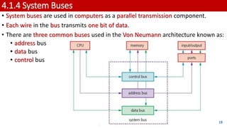
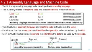
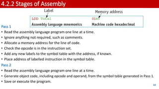
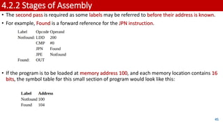
In the context of CIE 9618 syllabus
GCE AS LEVEL
4.1 Central Processing Unit (CPU) Architecture
4.2 Assembly Language
4.3 Bit Manipulation
4. Processor Fundamentals
LEARNING OBJECTIVES:
1. Von Neumann model of a computer system
2. The purpose and role of the registers PC, MDR, MAR, ACC, IX, CIR, and the status registers
3. The purpose and role of the arithmetic logic unit (ALU), control unit (CU), system clock and immediate access store
(IAS)
4. Functions of the address bus, data bus and control bus
5. Factors affecting computer performance (such as processor type, bus width, clock speeds, cache memory and use of
core processors)
6. The connection of computers to peripheral devices such as Universal Serial Bus (USB), high definition multimedia
interface (HDMI) and Video Graphics Array (VGA)
7. The fetch-execute cycle and register transfers
8. The purpose of interrupts
9. The relationship between assembly language and machine code (such as symbolic, absolute and relative addressing)
10. Different stages for a two-pass assembler
11. Tracing sample assembly language programming code
12. Assembly language instruction groups (such as data movement, I/O operations, arithmetic operations, comparisons,
and so on)
13. Addressing modes (immediate, direct, indirect, indexed and relative)
14. How to perform binary shifts (including logical, arithmetic, cyclic, left shift and right shift)
15. How bit manipulation is used to monitor/control a device. 2
4.1 Computers and their components
KEY TERMS: (1/4)
• Von Neumann architecture – computer architecture which introduced the concept of the stored
program in the 1940s.
• Arithmetic logic unit (ALU) – component in the processor which carries out all arithmetic and
logical operations.
• Control unit – ensures synchronisation of data flow and programs throughout the computer by
sending out control signals along the control bus.
• System clock – produces timing signals on the control bus to ensure synchronisation takes place.
• Immediate access store (IAS) – holds all data and programs needed to be accessed by the control
unit.
• Accumulator – temporary general purpose register which stores numerical values at any part of
a given operation.
• Register – temporary component in the processor which can be general or specific in its use
that holds data or instructions as part of the fetch-execute cycle.
• Status register – used when an instruction requires some form of arithmetic or logical
processing.
3
4.1 Computers and their components
KEY TERMS: (2/4)
• Flag – indicates the status of a bit in the status register, for example, N = 1 indicates the result
of an addition gives a negative value.
• Address bus – carries the addresses throughout the computer system.
• Data bus – allows data to be carried from processor to memory (and vice versa) or to and from
input/output devices.
• Control bus – carries signals from control unit to all other computer components.
• Unidirectional – used to describe a bus in which bits can travel in one direction only.
• Bidirectional – used to describe a bus in which bits can travel in both directions.
• Word – group of bits used by a computer to represent a single unit.
• Clock cycle – clock speeds are measured in terms of GHz; this is the vibrational frequency of
the clock which sends out pulses along the control bus – a 3.5 GHZ clock cycle means 3.5 billion
clock cycles a second.
4
4.1 Computers and their components
KEY TERMS: (3/4)
• Overclocking – changing the clock speed of a system clock to a value higher than the
factory/recommended setting.
• BIOS – basic input/output system.
• Cache memory – a high speed auxiliary memory which permits high speed data transfer and
retrieval.
• Core – a unit made up of ALU, control unit and registers which is part of a CPU. A CPU may
contain a number of cores.
• Dual core – a CPU containing two cores.
• Quad core – a CPU containing four cores.
• Port – external connection to a computer which allows it to communicate with various
peripheral devices. A number of different port technologies exist.
• Universal Serial Bus (USB) – a type of port connecting devices to a computer.
• Asynchronous serial data transmission – serial refers to a single wire being used to transmit bits
of data one after the other. Asynchronous refers to a sender using its own clock/timer device
rather sharing the same clock/timer with the recipient device.
5
4.1 Computers and their components
KEY TERMS: (4/4)
• High-definition multimedia interface (HDMI) – type of port connecting devices to a computer.
• Video Graphics Array (VGA) – type of port connecting devices to a computer. High-bandwidth
digital copy protection (HDCP) – part of HDMI technology which reduces risk of piracy of
software and multimedia.
• Fetch-execute cycle – a cycle in which instructions and data are fetched from memory and then
decoded and finally executed.
• Program counter (PC) – a register used in a computer to store the address of the instruction
which is currently being executed.
• Current instruction register – a register used to contain the instruction which is currently being
executed or decoded.
• Register Transfer Notation (RTN) – short hand notation to show movement of data and
instructions in a processor, can be used to represent the operation of the fetch-execute cycle.
• Interrupt – signal sent from a device or software to a processor requesting its attention; the
processor suspends all operations until the interrupt has been serviced.
• Interrupt priority – all interrupts are given a priority so that the processor knows which need to
be serviced first and which interrupts are to be dealt with quickly.
• Interrupt service routine (ISR) or interrupt handler – software which handles interrupt requests
(such as ‘printer out of paper’) and sends the request to the CPU for processing. 6
4.1.1 Von Newmann Model
• Early computers: Fed data while running, no program or data storage, required
human intervention.
• In the mid-1940s, John Von Neumann: Developed concept of stored program
computer.
• Stored program computer: Basis of computer architecture for years.
• Von Neumann architecture: Main features -
• Central Processing Unit (CPU): Also known as processor.
• Processor can access memory directly.
• Computer memories can store programs and data.
• Stored programs: Comprised sequential instructions for execution.
7
4.1.1 Von Newmann Model
8
Representation
of Von Neumann
architecture
4.1.2 Components of the processor (CPU)
1. Arithmetic logic unit (ALU):
• ALU (Arithmetic Logic Unit):
• Performs arithmetic and logic operations during program execution.
• Computer can have multiple ALUs:
• One for fixed-point operations and another for floating-point operations.
• Multiplication and division:
• Conducted through sequences of addition, subtraction, and left/right shifting
operations.
• Accumulator (ACC):
• Temporary register for ALU calculations.
9
4.1.2 Components of the processor (CPU)
2. Control unit (CU):
• Control Unit (CU):
• Reads instruction from memory (address stored in Program Counter (PC)).
• Read instruction is interpreted
• signals sent via control bus to guide other computer components.
• CU synchronizes data flow and program instructions across the computer.
10
4.1.2 Components of the processor (CPU)
3. System clock:
• System clock:
• Generates timing signals on control bus for vital synchronisation.
• Clock essential:
• Without it, computer would crash.
11
4.1.2 Components of the processor (CPU)
4. Immediate access store (IAS):
• IAS (Internal Storage):
• Contains data and programs for CPU access.
• CPU transfers data and programs from backing store to IAS temporarily.
• IAS read/write operations faster than backing store.
• Key data stored temporarily in IAS to accelerate operations.
• IAS is primary (RAM) memory:
• Also known as Internal Storage.
12
4.1.3 Registers
• Von Neumann system:
• Includes registers as important parts.
• Registers:
• Either general purpose or special purpose.
• General purpose:
• Hold often-used data, like the accumulator.
• Special purpose:
• Serve specific functions, holding program state.
13
4.1.3 Registers
Register Abbreviation Function/purpose of register
current instruction
register
CIR stores the current instruction being decoded and executed
index register IX
used when carrying out index addressing operations
(assembly code)
memory address
register
MAR
stores the address of the memory location currently being
read from or written to
memory data/buffer
register
MDR
/MBR
stores the address of the memory location currently being
read from or written to
program counter PC
stores the address where the next instruction to be read
can be found
status register SR
contain bits which can be set or cleared depending on the
operation (for example, to indicate overflow in a
calculation)
14
4.1.3 Registers
• All of the registers are used in the fetch-execute-cycle.
• Index registers are best explained when looking at addressing techniques in assembly code.
• A status register is used when an instruction requires some form of arithmetic or logic
processing.
• Each bit is known as a flag.
• Most systems have the following four flags:
• Carry flag (C)
• is set to 1 if there is a CARRY following an addition operation
• Negative flag (N)
• is set to 1 if the result of a calculation yields a NEGATIVE value
• Overflow flag (V)
• is set to 1 if an arithmetic operation results in an OVERFLOW being produced
• Zero flag (Z)
is set to 1 if the result of an arithmetic or logic operation is ZERO
15
4.1.3 Registers
• Consider this arithmetic operation:
• Since we have two positive numbers being added, the answer should not be negative.
• The flags indicate two errors:
• a negative result
• an overflow occurred.
16
0 1 1 1 0 1 1 1
+ 0 0 1 1 1 0 0 0
1 0 1 0 1 1 1 1
Flags:
N V C Z
1 1 0 0
4.1.3 Registers
• Now consider this operation:
• Since we have two negative numbers being added, the answer should be negative.
• The flags indicate that two errors have occurred:
• a carry has been generated
• a ninth bit overflow has occurred.
17
1 0 0 0 1 0 0 0
+ 1 1 0 0 0 1 1 1
1 0 1 0 0 1 1 1 1
Flags:
N V C Z
0 1 1 0
4.1.4 System Buses
• System buses are used in computers as a parallel transmission component.
• Each wire in the bus transmits one bit of data.
• There are three common buses used in the Von Neumann architecture known as:
• address bus
• data bus
• control bus
18
4.1.4 System Buses
1. Address Bus:
• Address bus:
• Carries addresses in the computer system.
• Between CPU and memory:
• Address bus is one-way to avoid issues (unidirectional).
• Bus width matters:
• Wider bus means more memory locations can be addressed at once.
• Example:
• 16-bit bus addresses 65,536 locations
• 32-bit bus addresses 4,294,967,296 locations.
19
4.1.4 System Buses
2. Data Bus:
• Data bus:
• Goes both ways (bidirectional).
• Moves data between CPU, memory, and input/output devices.
• Data can be:
• address, instruction, or number.
• Data bus width matters:
• Wider bus carries larger word lengths for better computer performance.
20
4.1.4 System Buses
3. Control Bus:
• The control bus is also bidirectional.
• It carries signals from the CU to all the other computer components.
• It is usually 8-bits wide since it only carries control signals.
21
4.1.4 System Buses
The role of the System Clock:
• Clock:
• Sets the timing for computer tasks.
• Control bus:
• Ensures synchronization.
• Higher clock speed:
• Faster processing (like 3.5 GHz – billion cycles/sec).
• Faster clock ≠Always better performance.
22
4.1.4 System Buses
Faster clock ≠Always better performance:
Four other factors need to be considered:
1. Width of the address bus and data bus can affect computer performance.
2. Overclocking:
• Change clock speed in BIOS settings.
• Higher clock than design can cause issues:
• Instructions exceed limits: Unsynced operations, crashes.
• CPU overheating: Causes unreliable performance.
23
4.1.4 System Buses
Faster clock ≠Always better performance:
Four other factors need to be considered:
3. Cache Memory
• Boosts processor performance.
• Like RAM, lost when power's off.
• Cache uses SRAM, faster than DRAM in main memory.
• Faster access, no refreshing delay.
• Processor checks cache first, then main memory.
• Cache stores frequently used instructions/data, speeds up access.
24
4.1.4 System Buses
Faster clock ≠Always better performance:
Four other factors need to be considered:
4. Cores:
• More cores:
• Improve computer performance.
• Many have dual core (2 cores) or quad core (4 cores).
• More cores reduce need to raise clock speeds.
• Doubling cores ≠Double performance:
• CPU communication affects it.
• Dual core:
• One channel, CPU talks to both cores, reduces potential increase.
• Quad core:
• Six channels, CPU talks to all cores, reduces potential performance.
25
Two cores, one channel (left) and
four cores, six channels (right)
4.1.5 Computer Ports
Computer Ports:
• Input and output devices:
• Connected via ports.
• Control unit manages port interaction with devices.
• Common types of ports in modern computers:
26
USB cable HDMI cable VGA cable
4.1.5 Computer Ports
USB ports:
• USB (Universal Serial Bus):
• Method to transfer data between computer and devices.
• USB cable:
• Four-wired shielded cable, power, earth, and data wires.
• Plugging in a device to a USB port:
• Computer detects device: Voltage change on data wires.
• Device recognized: Correct driver loaded for communication.
• New device: Computer searches for matching driver; download if needed.
27
4.1.5 Computer Ports
USB ports:
28
ADVANTAGES DISADVANTAGES
• Devices plugged in: Get detected and
drivers loaded automatically.
• Connectors fit only one way: Stops wrong
connections.
• Industry standard: Lots of support for users.
• Different data rates supported.
• Newer USB backward compatible: Works
with older standards too.
• Current rate: Under 500 megabits per
second.
• Max cable length: About 5 meters.
• Older USB standard: Might not be
supported soon.
4.1.5 Computer Ports
High-definition multimedia interface (HDMI):
• HDMI ports: Send audio and video from computer to HDMI devices.
• Support high-definition signals: Enhanced or standard.
• Replaces VGA for better digital quality.
• Modern HD TVs have:
• Widescreen format (16:9 ratio).
• More pixels (usually 1920 x 1080).
• Faster refresh rate (120 Hz or 120 frames/sec).
• Wide range of colors (up to four million variations).
• HD TVs need more data faster (around 10 gigabits/sec).
• HDMI increases bandwidth: Provides data for sound and visuals.
• HDCP protection: Guards against piracy using authentication protocol.
• Example: Blu-ray player checks TV's key before transmitting data. 29
4.1.5 Computer Ports
High-definition multimedia interface (HDMI):
30
ADVANTAGES DISADVANTAGES
• Current standard for TVs and monitors:
• Fast data transfer.
• Better security against piracy.
• Works with modern digital systems.
• Connection not strong (breaks easily when
moving).
• Limited cable length for good signal.
• Five cable/connection standards currently.
4.1.5 Computer Ports
Video Graphics Array (VGA):
• VGA introduced in late 1980s.
• VGA supports 640x480 pixels on screen.
• Refresh rate up to 60 Hz (60 frames/sec).
• For 16 colors, higher refresh rate.
• Lower pixel density (200x320) supports 256 colors.
31
4.1.5 Computer Ports
Video Graphics Array (VGA):
32
ADVANTAGES DISADVANTAGES
• Simple technology.
• Only one standard.
• Easy to split signal for many devices.
• Very secure connection.
• Old, outdated analog technology.
• Pins can bend easily when connecting.
• Need high-grade cables for clear signal.
4.1.6 Fetch-Execute Cycle
• Execution of Instructions:
• Processor fetches data and instructions from memory, stores in registers.
• Address bus and data bus used.
• Instructions decoded before execution.
• Fetch:
• Next instruction fetched from memory address in program counter (PC).
• Stored in current instruction register (CIR).
• PC incremented by 1 for next instruction.
• Decoded for interpretation in next cycle.
• Execute:
• Processor sends decoded instruction as control signals to system
components.
• Instructions carried out in logical sequence.
33
4.1.6 Fetch-Execute Cycle
How the fetch-execute cycle
is carried out in the
Von Neumann
computer model.
34
4.1.6 Fetch-Execute Cycle
• When registers are involved, it is possible to describe what is happening by using
Register Transfer Notation (RTN).
• Double brackets are used in the third line because it is not MAR contents being
copied into MDR but it is the data stored at the address shown in MAR that is
being copied to MDR.
35
4.1.6 Fetch-Execute Cycle
How interrupts are specifically used in the fetch-execute cycle:
• Interrupt Register in fetch-execute cycle:
• Interrupt can occur while CPU cycles.
• Interrupt changes interrupt register bit status.
• Sequence when interrupt happens:
• Next cycle: Interrupt register checked bit by bit.
• Contents like 0000 1000 mean unresolved interrupt.
• CPU services interrupt, depending on priority.
• CPU halts task, saves register contents.
• Control to interrupt handler.
• After service, register reset, registers restored.
36
4.1.6 Fetch-Execute Cycle
The interrupt process
during the
fetch-execute cycle.
37
4.1.7 Interrupts
• Interrupts in Simple Terms:
• Signal from device or software to processor.
• Makes processor pause and handle it.
• Interrupts can happen because of:
• Timing signal.
• Device ready (like a disk drive).
• Hardware problem (like a printer jam).
• User action (like pressing a key).
• Software issue (like a missing file or a divide by zero).
• Processor then continues or stops to help.
• Interrupts let computers do many things at once.
• Example: Downloading while playing music.
• When handling an interrupt:
• Save current task status.
• Run interrupt routine.
• After, go back to where it was before.
38
4.2 Assembly Language
KEY TERMS: (1/2)
• Machine code – the programming language that the CPU uses.
• Instruction – a single operation performed by a CPU.
• Assembly language – a low-level chip/machine specific programming language that uses
mnemonics.
• Opcode – short for operation code, the part of a machine code instruction that identifies the
action the CPU will perform.
• Operand – the part of a machine code instruction that identifies the data to be used by the
CPU.
• Source code – a computer program before translation into machine code.
• Assembler – a computer program that translates programming code written in assembly
language into machine code. Assemblers can be one pass or two pass.
• Instruction set – the complete set of machine code instructions used by a CPU.
• Object code – a computer program after translation into machine code.
39
4.2 Assembly Language
KEY TERMS: (2/2)
• Addressing modes – different methods of using the operand part of a machine code instruction
as a memory address.
• Absolute addressing – mode of addressing in which the contents of the memory location in the
operand are used.
• Direct addressing – mode of addressing in which the contents of the memory location in the
operand are used, which is the same as absolute addressing.
• Indirect addressing – mode of addressing in which the contents of the contents of the memory
location in the operand are used.
• Indexed addressing – mode of addressing in which the contents of the memory location found
by adding the contents of the index register (IR) to the address of the memory location in the
operand are used.
• Immediate addressing – mode of addressing in which the value of the operand only is used.
• Relative addressing – mode of addressing in which the memory address used is the current
memory address added to the operand.
• Symbolic addressing – mode of addressing used in assembly language programming, where a
label is used instead of a value. 40
4.2.1 Assembly Language and Machine Code
• Machine Code Basics:
• CPU uses machine code language.
• Each computer type has own instructions.
• Programs in Memory:
• Computer program in memory is a series of
instructions.
• CPU follows these during fetch-execute cycle.
• Simple Tasks:
• Each instruction does one simple task.
• Like putting a value in a certain spot.
• Machine Code is Binary:
• It's in 0s and 1s.
• Sometimes shown as hexadecimal for
programmers.
41
• Writing Machine Code:
• Special task, takes lots of time.
• Can be error-prone.
• Testing is hard, need to run and see.
• Other Languages Developed:
• Other languages easier for programmers.
• Translators Needed:
• Programs not in machine code need to be
translated.
• Language translators were made for this.
4.2.1 Assembly Language and Machine Code
• The first programming language to be developed was assembly language.
• This is closely related to machine code and uses mnemonics instead of binary.
• The structure of assembly language and machine code instructions is the same.
• Each instruction has an opcode that identifies the operation to be carried out by the CPU.
• Most instructions also have an operand that identifies the data to be used by the opcode.
42
4.2.2 Stages of Assembly
• From Assembly to Machine Code:
• Assembly code needs to become machine code.
• Assembler program does the job.
• Assembler's Job:
• Translates each assembly instruction to machine code.
• Checks if assembly code is right.
• Speeds up fixing errors before running.
• Types of Assemblers:
• Single pass: Puts code in memory for direct use.
• Two pass: Makes a machine code program, needs a loader.
• Two Pass Assembler:
• Goes through source program twice.
• Replaces labels with memory addresses.
43
4.2.2 Stages of Assembly
Pass 1
• Read the assembly language program one line at a time.
• Ignore anything not required, such as comments.
• Allocate a memory address for the line of code.
• Check the opcode is in the instruction set.
• Add any new labels to the symbol table with the address, if known.
• Place address of labelled instruction in the symbol table.
Pass 2
• Read the assembly language program one line at a time.
• Generate object code, including opcode and operand, from the symbol table generated in Pass 1.
• Save or execute the program.
44
4.2.2 Stages of Assembly
• The second pass is required as some labels may be referred to before their address is known.
• For example, Found is a forward reference for the JPN instruction.
• If the program is to be loaded at memory address 100, and each memory location contains 16
bits, the symbol table for this small section of program would look like this:
45
4.2.3 Assembly Language Instructions
Data movement instructions:
• These instructions allow data stored at
one location to be copied into the
accumulator.
• This data can then be stored at another
location, used in a calculation, used for
a comparison or output.
46
4.2.3 Assembly Language Instructions
Input and output of data instructions:
• These instructions allow data to be
read from the keyboard or output to
the screen.
Arithmetic operation instructions:
• These instructions perform simple
calculations on data stored in the
accumulator and store the answer in
the accumulator, overwriting the
original data.
47
4.2.3 Assembly Language Instructions
Unconditional and conditional
instructions:
Compare instructions:
48
4.2.4 Addressing Modes
Assembly language and machine code programs use different addressing modes depending on
the requirements of the program:
• Absolute addressing:
• The contents of the memory location in the operand are used.
• For example, if the memory location with address 200 contained the value 20, the assembly language
instruction LDD 200 would store 20 in the accumulator.
• Direct addressing:
• The contents of the memory location in the operand are used.
• For example, if the memory location with address 200 contained the value 20, the assembly language
instruction LDD 200 would store 20 in the accumulator.
• Absolute and direct addressing are the same.
• Indirect addressing:
• The contents of the contents of the memory location in the operand are used.
• For example, if the memory location with address 200 contained the value 20 and the memory location with
address 20 contained the value 5, the assembly language instruction LDI 200 would store 5 in the
accumulator.
49
4.2.4 Addressing Modes
Assembly language and machine code programs use different addressing modes depending on
the requirements of the program:
• Indexed addressing:
• The contents of the memory location found by adding the contents of the index register (IR) to the address
of the memory location in the operand are used.
• For example, if IR contained the value 4 and memory location with address 204 contained the value 17, the
assembly language instruction LDX 200 would store 17 in the accumulator.
• Immediate addressing:
• The value of the operand only is used.
• For example, the assembly language instruction LDM #200 would store 200 in the accumulator.
• Relative addressing:
• The memory address used is the current memory address added to the operand.
• For example, JMR #5 would transfer control to the instruction 5 locations after the current instruction.
50
4.2.4 Addressing Modes
Assembly language and machine code programs use different addressing modes depending on
the requirements of the program:
• Symbolic addressing:
• Only used in assembly language programming.
• A label is used instead of a value.
• For example, if the memory location with address labelled MyStore contained the value 20, the assembly
language instruction LDD MyStore would store 20 in the accumulator.
51
4.2.5 Simple assembly language programs
• A program written in assembly language will need many more instructions than a program
written in a high-level language to perform the same task.
• In a high-level language, adding three numbers together and storing the answer would typically
be written as a single instruction:
total = first + second + third
• The same task written in assembly language could look like this:
52
4.2.5 Simple assembly language programs
• If the program is to be loaded at memory address 100 after
translation and each memory location contains 16 bits,
the symbol table for this small section of program would
look like this:
• When this section of code is executed, the contents of
ACC, CIR and the variables used can be traced
using a trace table.
53
4.2.5 Simple assembly language programs
• In a high-level language, adding a list of numbers
together and storing the answer would typically be
written using a loop.
• The same task written in assembly
language would require the use of
the index register (IX).
• The assembly language program could
look like this:
54
4.2.5 Simple assembly language programs
• If the program is to be loaded at memory address 100 after translation
and each memory location contains 16 bits, the symbol table for this
small section of program would look like this:
• When this section of code is
executed the contents of
ACC, CIR, IX and the variables
used can be traced using
a trace table:
55
4.3 Bit Manipulation
KEY TERMS:
• Shift – moving the bits stored in a register a given number of places within the register; there
are different types of shift.
• Logical shift – bits shifted out of the register are replaced with zeros.
• Arithmetic shift – the sign of the number is preserved.
• Cyclic shift – no bits are lost, bits shifted out of one end of the register are introduced at the
other end of the register.
• Left shift – bits are shifted to the left.
• Right shift – bits are shifted to the right.
• Monitor – to automatically take readings from a device.
• Control – to automatically take readings from a device, then use the data from those readings
to adjust the device.
• Mask – a number that is used with the logical operators AND, OR or XOR to identify, remove or
set a single bit or group of bits in an address or register.
56
4.3.1 Binary Shifts
• Shift in Registers:
• Move bits within a register.
• Change positions by given number.
• Different Bit Uses:
• Bits in register serve various purposes.
• Example - IR Register:
• Each bit in IR identifies different interrupt.
57
4.3.1 Binary Shifts
Types of Shifts:
• Logical Shift: Bits out, replaced with zeros.
• Example: 10101111 -> Shift left 3 -> 01111000.
• Arithmetic Shift: Keeps sign, shifts.
• Example: 10101111 -> Shift right 3 -> 11110101.
• Used for multiplication/division by powers of two.
• Cyclic Shift: No bits lost.
• Bits out, wrap around to other end.
• Example: 10101111 -> Shift left 3 -> 01111101.
• Left Shift:
• Bits shifted left.
• Direction for logical, arithmetic, cyclic shifts.
• Right Shift:
• Bits shifted right.
• Direction for logical, arithmetic, cyclic shifts. 58
4.3.2 Bit manipulation used in monitoring and control
• Monitoring and Control:
• Bits as Flags: Test, set, or clear separately.
• Example - Sensor Data:
• Eight sensors: Track processed data.
• 8 bits in one memory location.
• Operations for Flags:
• AND: Checks if bit is set.
• OR: Sets the bit.
• XOR: Clears set bit.
59
4.3.2 Bit manipulation used in monitoring and control
Instructions used to check, set and clear a single bit or group of bits:
60
4.3.2 Bit manipulation used in monitoring and control
The assembly language code to test sensor 3 could be:
61

AS & A Level Computer Science Chapter 4 Presentation

  • 1.
    In the contextof CIE 9618 syllabus GCE AS LEVEL 4.1 Central Processing Unit (CPU) Architecture 4.2 Assembly Language 4.3 Bit Manipulation
  • 2.
    4. Processor Fundamentals LEARNINGOBJECTIVES: 1. Von Neumann model of a computer system 2. The purpose and role of the registers PC, MDR, MAR, ACC, IX, CIR, and the status registers 3. The purpose and role of the arithmetic logic unit (ALU), control unit (CU), system clock and immediate access store (IAS) 4. Functions of the address bus, data bus and control bus 5. Factors affecting computer performance (such as processor type, bus width, clock speeds, cache memory and use of core processors) 6. The connection of computers to peripheral devices such as Universal Serial Bus (USB), high definition multimedia interface (HDMI) and Video Graphics Array (VGA) 7. The fetch-execute cycle and register transfers 8. The purpose of interrupts 9. The relationship between assembly language and machine code (such as symbolic, absolute and relative addressing) 10. Different stages for a two-pass assembler 11. Tracing sample assembly language programming code 12. Assembly language instruction groups (such as data movement, I/O operations, arithmetic operations, comparisons, and so on) 13. Addressing modes (immediate, direct, indirect, indexed and relative) 14. How to perform binary shifts (including logical, arithmetic, cyclic, left shift and right shift) 15. How bit manipulation is used to monitor/control a device. 2
  • 3.
    4.1 Computers andtheir components KEY TERMS: (1/4) • Von Neumann architecture – computer architecture which introduced the concept of the stored program in the 1940s. • Arithmetic logic unit (ALU) – component in the processor which carries out all arithmetic and logical operations. • Control unit – ensures synchronisation of data flow and programs throughout the computer by sending out control signals along the control bus. • System clock – produces timing signals on the control bus to ensure synchronisation takes place. • Immediate access store (IAS) – holds all data and programs needed to be accessed by the control unit. • Accumulator – temporary general purpose register which stores numerical values at any part of a given operation. • Register – temporary component in the processor which can be general or specific in its use that holds data or instructions as part of the fetch-execute cycle. • Status register – used when an instruction requires some form of arithmetic or logical processing. 3
  • 4.
    4.1 Computers andtheir components KEY TERMS: (2/4) • Flag – indicates the status of a bit in the status register, for example, N = 1 indicates the result of an addition gives a negative value. • Address bus – carries the addresses throughout the computer system. • Data bus – allows data to be carried from processor to memory (and vice versa) or to and from input/output devices. • Control bus – carries signals from control unit to all other computer components. • Unidirectional – used to describe a bus in which bits can travel in one direction only. • Bidirectional – used to describe a bus in which bits can travel in both directions. • Word – group of bits used by a computer to represent a single unit. • Clock cycle – clock speeds are measured in terms of GHz; this is the vibrational frequency of the clock which sends out pulses along the control bus – a 3.5 GHZ clock cycle means 3.5 billion clock cycles a second. 4
  • 5.
    4.1 Computers andtheir components KEY TERMS: (3/4) • Overclocking – changing the clock speed of a system clock to a value higher than the factory/recommended setting. • BIOS – basic input/output system. • Cache memory – a high speed auxiliary memory which permits high speed data transfer and retrieval. • Core – a unit made up of ALU, control unit and registers which is part of a CPU. A CPU may contain a number of cores. • Dual core – a CPU containing two cores. • Quad core – a CPU containing four cores. • Port – external connection to a computer which allows it to communicate with various peripheral devices. A number of different port technologies exist. • Universal Serial Bus (USB) – a type of port connecting devices to a computer. • Asynchronous serial data transmission – serial refers to a single wire being used to transmit bits of data one after the other. Asynchronous refers to a sender using its own clock/timer device rather sharing the same clock/timer with the recipient device. 5
  • 6.
    4.1 Computers andtheir components KEY TERMS: (4/4) • High-definition multimedia interface (HDMI) – type of port connecting devices to a computer. • Video Graphics Array (VGA) – type of port connecting devices to a computer. High-bandwidth digital copy protection (HDCP) – part of HDMI technology which reduces risk of piracy of software and multimedia. • Fetch-execute cycle – a cycle in which instructions and data are fetched from memory and then decoded and finally executed. • Program counter (PC) – a register used in a computer to store the address of the instruction which is currently being executed. • Current instruction register – a register used to contain the instruction which is currently being executed or decoded. • Register Transfer Notation (RTN) – short hand notation to show movement of data and instructions in a processor, can be used to represent the operation of the fetch-execute cycle. • Interrupt – signal sent from a device or software to a processor requesting its attention; the processor suspends all operations until the interrupt has been serviced. • Interrupt priority – all interrupts are given a priority so that the processor knows which need to be serviced first and which interrupts are to be dealt with quickly. • Interrupt service routine (ISR) or interrupt handler – software which handles interrupt requests (such as ‘printer out of paper’) and sends the request to the CPU for processing. 6
  • 7.
    4.1.1 Von NewmannModel • Early computers: Fed data while running, no program or data storage, required human intervention. • In the mid-1940s, John Von Neumann: Developed concept of stored program computer. • Stored program computer: Basis of computer architecture for years. • Von Neumann architecture: Main features - • Central Processing Unit (CPU): Also known as processor. • Processor can access memory directly. • Computer memories can store programs and data. • Stored programs: Comprised sequential instructions for execution. 7
  • 8.
    4.1.1 Von NewmannModel 8 Representation of Von Neumann architecture
  • 9.
    4.1.2 Components ofthe processor (CPU) 1. Arithmetic logic unit (ALU): • ALU (Arithmetic Logic Unit): • Performs arithmetic and logic operations during program execution. • Computer can have multiple ALUs: • One for fixed-point operations and another for floating-point operations. • Multiplication and division: • Conducted through sequences of addition, subtraction, and left/right shifting operations. • Accumulator (ACC): • Temporary register for ALU calculations. 9
  • 10.
    4.1.2 Components ofthe processor (CPU) 2. Control unit (CU): • Control Unit (CU): • Reads instruction from memory (address stored in Program Counter (PC)). • Read instruction is interpreted • signals sent via control bus to guide other computer components. • CU synchronizes data flow and program instructions across the computer. 10
  • 11.
    4.1.2 Components ofthe processor (CPU) 3. System clock: • System clock: • Generates timing signals on control bus for vital synchronisation. • Clock essential: • Without it, computer would crash. 11
  • 12.
    4.1.2 Components ofthe processor (CPU) 4. Immediate access store (IAS): • IAS (Internal Storage): • Contains data and programs for CPU access. • CPU transfers data and programs from backing store to IAS temporarily. • IAS read/write operations faster than backing store. • Key data stored temporarily in IAS to accelerate operations. • IAS is primary (RAM) memory: • Also known as Internal Storage. 12
  • 13.
    4.1.3 Registers • VonNeumann system: • Includes registers as important parts. • Registers: • Either general purpose or special purpose. • General purpose: • Hold often-used data, like the accumulator. • Special purpose: • Serve specific functions, holding program state. 13
  • 14.
    4.1.3 Registers Register AbbreviationFunction/purpose of register current instruction register CIR stores the current instruction being decoded and executed index register IX used when carrying out index addressing operations (assembly code) memory address register MAR stores the address of the memory location currently being read from or written to memory data/buffer register MDR /MBR stores the address of the memory location currently being read from or written to program counter PC stores the address where the next instruction to be read can be found status register SR contain bits which can be set or cleared depending on the operation (for example, to indicate overflow in a calculation) 14
  • 15.
    4.1.3 Registers • Allof the registers are used in the fetch-execute-cycle. • Index registers are best explained when looking at addressing techniques in assembly code. • A status register is used when an instruction requires some form of arithmetic or logic processing. • Each bit is known as a flag. • Most systems have the following four flags: • Carry flag (C) • is set to 1 if there is a CARRY following an addition operation • Negative flag (N) • is set to 1 if the result of a calculation yields a NEGATIVE value • Overflow flag (V) • is set to 1 if an arithmetic operation results in an OVERFLOW being produced • Zero flag (Z) is set to 1 if the result of an arithmetic or logic operation is ZERO 15
  • 16.
    4.1.3 Registers • Considerthis arithmetic operation: • Since we have two positive numbers being added, the answer should not be negative. • The flags indicate two errors: • a negative result • an overflow occurred. 16 0 1 1 1 0 1 1 1 + 0 0 1 1 1 0 0 0 1 0 1 0 1 1 1 1 Flags: N V C Z 1 1 0 0
  • 17.
    4.1.3 Registers • Nowconsider this operation: • Since we have two negative numbers being added, the answer should be negative. • The flags indicate that two errors have occurred: • a carry has been generated • a ninth bit overflow has occurred. 17 1 0 0 0 1 0 0 0 + 1 1 0 0 0 1 1 1 1 0 1 0 0 1 1 1 1 Flags: N V C Z 0 1 1 0
  • 18.
    4.1.4 System Buses •System buses are used in computers as a parallel transmission component. • Each wire in the bus transmits one bit of data. • There are three common buses used in the Von Neumann architecture known as: • address bus • data bus • control bus 18
  • 19.
    4.1.4 System Buses 1.Address Bus: • Address bus: • Carries addresses in the computer system. • Between CPU and memory: • Address bus is one-way to avoid issues (unidirectional). • Bus width matters: • Wider bus means more memory locations can be addressed at once. • Example: • 16-bit bus addresses 65,536 locations • 32-bit bus addresses 4,294,967,296 locations. 19
  • 20.
    4.1.4 System Buses 2.Data Bus: • Data bus: • Goes both ways (bidirectional). • Moves data between CPU, memory, and input/output devices. • Data can be: • address, instruction, or number. • Data bus width matters: • Wider bus carries larger word lengths for better computer performance. 20
  • 21.
    4.1.4 System Buses 3.Control Bus: • The control bus is also bidirectional. • It carries signals from the CU to all the other computer components. • It is usually 8-bits wide since it only carries control signals. 21
  • 22.
    4.1.4 System Buses Therole of the System Clock: • Clock: • Sets the timing for computer tasks. • Control bus: • Ensures synchronization. • Higher clock speed: • Faster processing (like 3.5 GHz – billion cycles/sec). • Faster clock ≠Always better performance. 22
  • 23.
    4.1.4 System Buses Fasterclock ≠Always better performance: Four other factors need to be considered: 1. Width of the address bus and data bus can affect computer performance. 2. Overclocking: • Change clock speed in BIOS settings. • Higher clock than design can cause issues: • Instructions exceed limits: Unsynced operations, crashes. • CPU overheating: Causes unreliable performance. 23
  • 24.
    4.1.4 System Buses Fasterclock ≠Always better performance: Four other factors need to be considered: 3. Cache Memory • Boosts processor performance. • Like RAM, lost when power's off. • Cache uses SRAM, faster than DRAM in main memory. • Faster access, no refreshing delay. • Processor checks cache first, then main memory. • Cache stores frequently used instructions/data, speeds up access. 24
  • 25.
    4.1.4 System Buses Fasterclock ≠Always better performance: Four other factors need to be considered: 4. Cores: • More cores: • Improve computer performance. • Many have dual core (2 cores) or quad core (4 cores). • More cores reduce need to raise clock speeds. • Doubling cores ≠Double performance: • CPU communication affects it. • Dual core: • One channel, CPU talks to both cores, reduces potential increase. • Quad core: • Six channels, CPU talks to all cores, reduces potential performance. 25 Two cores, one channel (left) and four cores, six channels (right)
  • 26.
    4.1.5 Computer Ports ComputerPorts: • Input and output devices: • Connected via ports. • Control unit manages port interaction with devices. • Common types of ports in modern computers: 26 USB cable HDMI cable VGA cable
  • 27.
    4.1.5 Computer Ports USBports: • USB (Universal Serial Bus): • Method to transfer data between computer and devices. • USB cable: • Four-wired shielded cable, power, earth, and data wires. • Plugging in a device to a USB port: • Computer detects device: Voltage change on data wires. • Device recognized: Correct driver loaded for communication. • New device: Computer searches for matching driver; download if needed. 27
  • 28.
    4.1.5 Computer Ports USBports: 28 ADVANTAGES DISADVANTAGES • Devices plugged in: Get detected and drivers loaded automatically. • Connectors fit only one way: Stops wrong connections. • Industry standard: Lots of support for users. • Different data rates supported. • Newer USB backward compatible: Works with older standards too. • Current rate: Under 500 megabits per second. • Max cable length: About 5 meters. • Older USB standard: Might not be supported soon.
  • 29.
    4.1.5 Computer Ports High-definitionmultimedia interface (HDMI): • HDMI ports: Send audio and video from computer to HDMI devices. • Support high-definition signals: Enhanced or standard. • Replaces VGA for better digital quality. • Modern HD TVs have: • Widescreen format (16:9 ratio). • More pixels (usually 1920 x 1080). • Faster refresh rate (120 Hz or 120 frames/sec). • Wide range of colors (up to four million variations). • HD TVs need more data faster (around 10 gigabits/sec). • HDMI increases bandwidth: Provides data for sound and visuals. • HDCP protection: Guards against piracy using authentication protocol. • Example: Blu-ray player checks TV's key before transmitting data. 29
  • 30.
    4.1.5 Computer Ports High-definitionmultimedia interface (HDMI): 30 ADVANTAGES DISADVANTAGES • Current standard for TVs and monitors: • Fast data transfer. • Better security against piracy. • Works with modern digital systems. • Connection not strong (breaks easily when moving). • Limited cable length for good signal. • Five cable/connection standards currently.
  • 31.
    4.1.5 Computer Ports VideoGraphics Array (VGA): • VGA introduced in late 1980s. • VGA supports 640x480 pixels on screen. • Refresh rate up to 60 Hz (60 frames/sec). • For 16 colors, higher refresh rate. • Lower pixel density (200x320) supports 256 colors. 31
  • 32.
    4.1.5 Computer Ports VideoGraphics Array (VGA): 32 ADVANTAGES DISADVANTAGES • Simple technology. • Only one standard. • Easy to split signal for many devices. • Very secure connection. • Old, outdated analog technology. • Pins can bend easily when connecting. • Need high-grade cables for clear signal.
  • 33.
    4.1.6 Fetch-Execute Cycle •Execution of Instructions: • Processor fetches data and instructions from memory, stores in registers. • Address bus and data bus used. • Instructions decoded before execution. • Fetch: • Next instruction fetched from memory address in program counter (PC). • Stored in current instruction register (CIR). • PC incremented by 1 for next instruction. • Decoded for interpretation in next cycle. • Execute: • Processor sends decoded instruction as control signals to system components. • Instructions carried out in logical sequence. 33
  • 34.
    4.1.6 Fetch-Execute Cycle Howthe fetch-execute cycle is carried out in the Von Neumann computer model. 34
  • 35.
    4.1.6 Fetch-Execute Cycle •When registers are involved, it is possible to describe what is happening by using Register Transfer Notation (RTN). • Double brackets are used in the third line because it is not MAR contents being copied into MDR but it is the data stored at the address shown in MAR that is being copied to MDR. 35
  • 36.
    4.1.6 Fetch-Execute Cycle Howinterrupts are specifically used in the fetch-execute cycle: • Interrupt Register in fetch-execute cycle: • Interrupt can occur while CPU cycles. • Interrupt changes interrupt register bit status. • Sequence when interrupt happens: • Next cycle: Interrupt register checked bit by bit. • Contents like 0000 1000 mean unresolved interrupt. • CPU services interrupt, depending on priority. • CPU halts task, saves register contents. • Control to interrupt handler. • After service, register reset, registers restored. 36
  • 37.
    4.1.6 Fetch-Execute Cycle Theinterrupt process during the fetch-execute cycle. 37
  • 38.
    4.1.7 Interrupts • Interruptsin Simple Terms: • Signal from device or software to processor. • Makes processor pause and handle it. • Interrupts can happen because of: • Timing signal. • Device ready (like a disk drive). • Hardware problem (like a printer jam). • User action (like pressing a key). • Software issue (like a missing file or a divide by zero). • Processor then continues or stops to help. • Interrupts let computers do many things at once. • Example: Downloading while playing music. • When handling an interrupt: • Save current task status. • Run interrupt routine. • After, go back to where it was before. 38
  • 39.
    4.2 Assembly Language KEYTERMS: (1/2) • Machine code – the programming language that the CPU uses. • Instruction – a single operation performed by a CPU. • Assembly language – a low-level chip/machine specific programming language that uses mnemonics. • Opcode – short for operation code, the part of a machine code instruction that identifies the action the CPU will perform. • Operand – the part of a machine code instruction that identifies the data to be used by the CPU. • Source code – a computer program before translation into machine code. • Assembler – a computer program that translates programming code written in assembly language into machine code. Assemblers can be one pass or two pass. • Instruction set – the complete set of machine code instructions used by a CPU. • Object code – a computer program after translation into machine code. 39
  • 40.
    4.2 Assembly Language KEYTERMS: (2/2) • Addressing modes – different methods of using the operand part of a machine code instruction as a memory address. • Absolute addressing – mode of addressing in which the contents of the memory location in the operand are used. • Direct addressing – mode of addressing in which the contents of the memory location in the operand are used, which is the same as absolute addressing. • Indirect addressing – mode of addressing in which the contents of the contents of the memory location in the operand are used. • Indexed addressing – mode of addressing in which the contents of the memory location found by adding the contents of the index register (IR) to the address of the memory location in the operand are used. • Immediate addressing – mode of addressing in which the value of the operand only is used. • Relative addressing – mode of addressing in which the memory address used is the current memory address added to the operand. • Symbolic addressing – mode of addressing used in assembly language programming, where a label is used instead of a value. 40
  • 41.
    4.2.1 Assembly Languageand Machine Code • Machine Code Basics: • CPU uses machine code language. • Each computer type has own instructions. • Programs in Memory: • Computer program in memory is a series of instructions. • CPU follows these during fetch-execute cycle. • Simple Tasks: • Each instruction does one simple task. • Like putting a value in a certain spot. • Machine Code is Binary: • It's in 0s and 1s. • Sometimes shown as hexadecimal for programmers. 41 • Writing Machine Code: • Special task, takes lots of time. • Can be error-prone. • Testing is hard, need to run and see. • Other Languages Developed: • Other languages easier for programmers. • Translators Needed: • Programs not in machine code need to be translated. • Language translators were made for this.
  • 42.
    4.2.1 Assembly Languageand Machine Code • The first programming language to be developed was assembly language. • This is closely related to machine code and uses mnemonics instead of binary. • The structure of assembly language and machine code instructions is the same. • Each instruction has an opcode that identifies the operation to be carried out by the CPU. • Most instructions also have an operand that identifies the data to be used by the opcode. 42
  • 43.
    4.2.2 Stages ofAssembly • From Assembly to Machine Code: • Assembly code needs to become machine code. • Assembler program does the job. • Assembler's Job: • Translates each assembly instruction to machine code. • Checks if assembly code is right. • Speeds up fixing errors before running. • Types of Assemblers: • Single pass: Puts code in memory for direct use. • Two pass: Makes a machine code program, needs a loader. • Two Pass Assembler: • Goes through source program twice. • Replaces labels with memory addresses. 43
  • 44.
    4.2.2 Stages ofAssembly Pass 1 • Read the assembly language program one line at a time. • Ignore anything not required, such as comments. • Allocate a memory address for the line of code. • Check the opcode is in the instruction set. • Add any new labels to the symbol table with the address, if known. • Place address of labelled instruction in the symbol table. Pass 2 • Read the assembly language program one line at a time. • Generate object code, including opcode and operand, from the symbol table generated in Pass 1. • Save or execute the program. 44
  • 45.
    4.2.2 Stages ofAssembly • The second pass is required as some labels may be referred to before their address is known. • For example, Found is a forward reference for the JPN instruction. • If the program is to be loaded at memory address 100, and each memory location contains 16 bits, the symbol table for this small section of program would look like this: 45
  • 46.
    4.2.3 Assembly LanguageInstructions Data movement instructions: • These instructions allow data stored at one location to be copied into the accumulator. • This data can then be stored at another location, used in a calculation, used for a comparison or output. 46
  • 47.
    4.2.3 Assembly LanguageInstructions Input and output of data instructions: • These instructions allow data to be read from the keyboard or output to the screen. Arithmetic operation instructions: • These instructions perform simple calculations on data stored in the accumulator and store the answer in the accumulator, overwriting the original data. 47
  • 48.
    4.2.3 Assembly LanguageInstructions Unconditional and conditional instructions: Compare instructions: 48
  • 49.
    4.2.4 Addressing Modes Assemblylanguage and machine code programs use different addressing modes depending on the requirements of the program: • Absolute addressing: • The contents of the memory location in the operand are used. • For example, if the memory location with address 200 contained the value 20, the assembly language instruction LDD 200 would store 20 in the accumulator. • Direct addressing: • The contents of the memory location in the operand are used. • For example, if the memory location with address 200 contained the value 20, the assembly language instruction LDD 200 would store 20 in the accumulator. • Absolute and direct addressing are the same. • Indirect addressing: • The contents of the contents of the memory location in the operand are used. • For example, if the memory location with address 200 contained the value 20 and the memory location with address 20 contained the value 5, the assembly language instruction LDI 200 would store 5 in the accumulator. 49
  • 50.
    4.2.4 Addressing Modes Assemblylanguage and machine code programs use different addressing modes depending on the requirements of the program: • Indexed addressing: • The contents of the memory location found by adding the contents of the index register (IR) to the address of the memory location in the operand are used. • For example, if IR contained the value 4 and memory location with address 204 contained the value 17, the assembly language instruction LDX 200 would store 17 in the accumulator. • Immediate addressing: • The value of the operand only is used. • For example, the assembly language instruction LDM #200 would store 200 in the accumulator. • Relative addressing: • The memory address used is the current memory address added to the operand. • For example, JMR #5 would transfer control to the instruction 5 locations after the current instruction. 50
  • 51.
    4.2.4 Addressing Modes Assemblylanguage and machine code programs use different addressing modes depending on the requirements of the program: • Symbolic addressing: • Only used in assembly language programming. • A label is used instead of a value. • For example, if the memory location with address labelled MyStore contained the value 20, the assembly language instruction LDD MyStore would store 20 in the accumulator. 51
  • 52.
    4.2.5 Simple assemblylanguage programs • A program written in assembly language will need many more instructions than a program written in a high-level language to perform the same task. • In a high-level language, adding three numbers together and storing the answer would typically be written as a single instruction: total = first + second + third • The same task written in assembly language could look like this: 52
  • 53.
    4.2.5 Simple assemblylanguage programs • If the program is to be loaded at memory address 100 after translation and each memory location contains 16 bits, the symbol table for this small section of program would look like this: • When this section of code is executed, the contents of ACC, CIR and the variables used can be traced using a trace table. 53
  • 54.
    4.2.5 Simple assemblylanguage programs • In a high-level language, adding a list of numbers together and storing the answer would typically be written using a loop. • The same task written in assembly language would require the use of the index register (IX). • The assembly language program could look like this: 54
  • 55.
    4.2.5 Simple assemblylanguage programs • If the program is to be loaded at memory address 100 after translation and each memory location contains 16 bits, the symbol table for this small section of program would look like this: • When this section of code is executed the contents of ACC, CIR, IX and the variables used can be traced using a trace table: 55
  • 56.
    4.3 Bit Manipulation KEYTERMS: • Shift – moving the bits stored in a register a given number of places within the register; there are different types of shift. • Logical shift – bits shifted out of the register are replaced with zeros. • Arithmetic shift – the sign of the number is preserved. • Cyclic shift – no bits are lost, bits shifted out of one end of the register are introduced at the other end of the register. • Left shift – bits are shifted to the left. • Right shift – bits are shifted to the right. • Monitor – to automatically take readings from a device. • Control – to automatically take readings from a device, then use the data from those readings to adjust the device. • Mask – a number that is used with the logical operators AND, OR or XOR to identify, remove or set a single bit or group of bits in an address or register. 56
  • 57.
    4.3.1 Binary Shifts •Shift in Registers: • Move bits within a register. • Change positions by given number. • Different Bit Uses: • Bits in register serve various purposes. • Example - IR Register: • Each bit in IR identifies different interrupt. 57
  • 58.
    4.3.1 Binary Shifts Typesof Shifts: • Logical Shift: Bits out, replaced with zeros. • Example: 10101111 -> Shift left 3 -> 01111000. • Arithmetic Shift: Keeps sign, shifts. • Example: 10101111 -> Shift right 3 -> 11110101. • Used for multiplication/division by powers of two. • Cyclic Shift: No bits lost. • Bits out, wrap around to other end. • Example: 10101111 -> Shift left 3 -> 01111101. • Left Shift: • Bits shifted left. • Direction for logical, arithmetic, cyclic shifts. • Right Shift: • Bits shifted right. • Direction for logical, arithmetic, cyclic shifts. 58
  • 59.
    4.3.2 Bit manipulationused in monitoring and control • Monitoring and Control: • Bits as Flags: Test, set, or clear separately. • Example - Sensor Data: • Eight sensors: Track processed data. • 8 bits in one memory location. • Operations for Flags: • AND: Checks if bit is set. • OR: Sets the bit. • XOR: Clears set bit. 59
  • 60.
    4.3.2 Bit manipulationused in monitoring and control Instructions used to check, set and clear a single bit or group of bits: 60
  • 61.
    4.3.2 Bit manipulationused in monitoring and control The assembly language code to test sensor 3 could be: 61