
Recommended
Recommended
More Related Content
Similar to 2006 Pontiac GTO Service Repair Manual.pdf
Similar to 2006 Pontiac GTO Service Repair Manual.pdf (6)
More from fujsekm8didd
More from fujsekm8didd (20)
Recently uploaded
Recently uploaded (20)
2006 Pontiac GTO Service Repair Manual.pdf
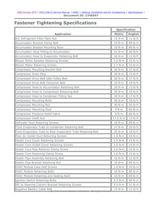
- 1. 2005 Pontiac GTO | GTO (VIN V) Service Manual | HVAC | Heating, Ventilation and Air Conditioning | Specifications | Document ID: 1340597 Fastener Tightening Specifications Application Specification Metric English A/C Refrigerant Filter Flare Nut 15 N·m 11 lb ft Accumulator Bracket Clamp Bolt 10 N·m 89 lb in Accumulator Bracket Mounting Nuts 10 N·m 89 lb in Accumulator Hose Fitting to Accumulator 41 N·m 30 lb ft Accumulator Hose to Evaporator Retaining Bolt 16 N·m 12 lb ft Blower Motor Resistor Retaining Screws 1.6 N·m 14 lb in Blower Motor Retaining Screws 1.7 N·m 15 lb in Compressor Mounting Bracket Bolt 50 N·m 37 lb ft Compressor Drain Plug 20 N·m 15 lb ft Compressor Drive Belt Idler Pulley Bolt 50 N·m 37 lb ft Compressor Drive Belt Tensioner Bolt 25 N·m 18 lb ft Compressor Hose to Accumulator Retaining Bolt 20 N·m 15 lb ft Compressor Hose to Compressor Retaining Bolt 26 N·m 19 lb ft Compressor Hose to Condenser Fitting Nut 24 N·m 17 lb ft Compressor Mounting Bolts 40 N·m 30 lb ft Compressor Mounting Nut 40 N·m 30 lb ft Compressor Mounting Stud 9 N·m 80 lb in Compressor Pressure Relief Valve 9 N·m 80 lb in Compressor Shaft Nut 17.5 N·m 13 lb ft Defroster Duct Retaining Screws 10 N·m 89 lb in Front Evaporator Tube to Condenser Retaining Bolt 27 N·m 20 lb ft Front Evaporator Tube to Rear Evaporator Tube Retaining Bolt 25 N·m 18 lb ft Floor Air Outlet Duct Retaining Screws 1.6 N·m 14 lb in Heater Core Cover Retaining Screws 1.6 N·m 14 lb in Heater Core Outlet Cover Retaining Screws 1.6 N·m 14 lb in Heater Core Pipe Retainer Clamp Screw 1.6 N·m 14 lb in Heater Core Retaining Clamp Screw 1.6 N·m 14 lb in Heater Pipe Assembly Retaining Bolt 16 N·m 12 lb ft Heater Pipe Bracket Retaining Nut 10 N·m 89 lb in HVAC Module Case Half Screws 1.6 N·m 14 lb in HVAC Module Retaining Bolts 10 N·m 89 lb in HVAC Module Retaining and Sealing Nuts 10 N·m 89 lb in Ignition Switch Retaining Bolts 5.5 N·m 49 lb in IPC to Steering Column Bracket Retaining Screws 3.5 N·m 31 lb in Negative Battery Cable Bolt 15 N·m 11 lb ft © 2010 General Motors Corporation. All rights reserved. Page 1 of 2 Document ID: 1340597 10/6/2010 http://localhost:9001/si/showDoc.do?docSyskey=1340597&pubCellSyskey=48114&pubO...
- 2. Refrigerant Pressure Sensor 4.75 N·m 42 lb in Temperature Actuator Retaining Screws 1.5 N·m 13 lb in Vacuum Tank Retaining Screws 3.5 N·m 31 lb in Valve Core 11 N·m 97 lb in Page 2 of 2 Document ID: 1340597 10/6/2010 http://localhost:9001/si/showDoc.do?docSyskey=1340597&pubCellSyskey=48114&pubO...
- 3. 2005 Pontiac GTO | GTO (VIN V) Service Manual | HVAC | Heating, Ventilation and Air Conditioning | Specifications | Document ID: 1340447 Refrigerant System Capacities Application Specification Metric English PAG Oil GM P/N 12378526 for United States PAG Oil GM P/N 88900060 for Canada Accumulator Replacement 60 ml* 2 oz* l * Add PAG oil equal to the amount of oil drained from the accumulator plus the specified additional amount. Compressor Replacement 60 ml¹ 2 oz¹ l Delphi Model V-7 service compressor is shipped dry Condenser Replacement 60 ml¹ 2 oz¹ Evaporator Replacement 60 ml¹ 2 oz¹ l Total System PAG Oil Capacity 266.16 ml 9 oz R-134a l Refrigerant Charge 0.79 kg 1.75 lb ¹ If more than the specified amount of PAG oil was drained from a component, add the equal amount drained. © 2010 General Motors Corporation. All rights reserved. Page 1 of 1 Document ID: 1340447 10/6/2010 http://localhost:9001/si/showDoc.do?docSyskey=1340447&pubCellSyskey=62330&pubO...
- 4. 2005 Pontiac GTO | GTO (VIN V) Service Manual | HVAC | Heating, Ventilation and Air Conditioning | Repair Instructions | Document ID: 1340598 Odor Correction Odors may be emitted from the air conditioning system primarily at start up in hot, humid climates. The following conditions may cause the odor: When the blower motor fan is turned on, the microbial growth may release an unpleasant musty odor into the passenger compartment. To remove odors of this type, the mirocbial growth must be eliminated. Perform the following procedure: Deodorize the evaporator core using Deodorizing Aerosol Kit. Perform the following steps in order to deodorize the A/C system: 1. Ensure that the plenum that draws outside air into the HVAC module is clear of debris. 2. Disable the A/C compressor clutch operation by disconnecting the clutch coil electrical connector. 3. Dry the evaporator core by performing the following steps: 4. Locate an area in the air conditioning duct between the blower motor and the evaporator core downstream of the blower motor. 5. Drill a 3.175 mm (0.125 in) hole where the hole will not interfere with or damage the following components: 6. Wear safety goggles and latex gloves in order to perform the following actions: 7. Shut the engine OFF. Allow the vehicle to sit for 3-5 minutes. 8. Seal the 3.175 mm (0.125 in) hole with body sealer or RTV gasket compound. 9. Start the engine. 10. Operate the blower motor on high for 15-20 minutes to dry. 11. Reconnect the A/C compressor clutch coil electrical connector. 12. Verify proper clutch operation. • Debris is present in the HVAC module. • Microbial growth on the evaporator core 3.1. Start the engine. 3.2. Select the maximum temperature setting. 3.3. Select the recirculation mode. 3.4. Run the blower motor on high for 10 minutes. • The blower motor • The evaporator core • Any other operating part the of system 6.1. Select the maximum blower speed. 6.2. Insert the deodorizer extension tube into the hole to the mark on the extension tube. 6.3. Use short spray bursts and vary the direction of spray for a 2-3 minute period of time. © 2010 General Motors Corporation. All rights reserved. Page 1 of 1 Document ID: 1340598 10/6/2010 http://localhost:9001/si/showDoc.do?docSyskey=1340598&pubCellSyskey=48169&pubO...
- 5. 2005 Pontiac GTO | GTO (VIN V) Service Manual | HVAC | Heating, Ventilation and Air Conditioning | Repair Instructions | Document ID: 1340428 Refrigerant Recovery and Recharging Tools Required Caution: Avoid breathing the A/C Refrigerant 134a (R-134a) and the lubricant vapor or the mist. Exposure may irritate the eyes, nose, and throat. Work in a well ventilated area. In order to remove R-134a from the A/C system, use service equipment that is certified to meet the requirements of SAE J 2210 (R-134a recycling equipment). If an accidental system discharge occurs, ventilate the work area before continuing service. Additional health and safety information may be obtained from the refrigerant and lubricant manufacturers. Caution: For personal protection, goggles and lint-free gloves should be worn and a clean cloth wrapped around fittings, valves, and connections when doing work that includes opening the refrigerant system. If refrigerant comes in contact with any part of the body severe frostbite and personal injury can result. The exposed area should be flushed immediately with cold water and prompt medical help should be obtained. Notice: R-134a is the only approved refrigerant for use in this vehicle. The use of any other refrigerant may result in poor system performance or component failure. Notice: To avoid system damage use only R-134a dedicated tools when servicing the A/C system. Notice: Use only Polyalkylene Glycol Synthetic Refrigerant Oil (PAG) for internal circulation through the R-134a A/C system and only 525 viscosity mineral oil on fitting threads and O-rings. If lubricants other than those specified are used, compressor failure and/or fitting seizure may result. Notice: R-12 refrigerant and R-134a refrigerant must never be mixed, even in the smallest of amounts, as they are incompatible with each other. If the refrigerants are mixed, compressor failure is likely to occur. Refer to the manufacturer instructions included with the service equipment before servicing. The J 43600 is a complete air conditioning service center for R-134a. The ACR 2000 recovers, recycles, evacuates and recharges A/C refrigerant quickly, accurately and automatically. The unit has a display screen that contains the function controls and displays prompts that will lead the technician through the recover, recycle, evacuate and recharge operations. R-134a is recovered into and charged out of an internal storage vessel. The ACR 2000 automatically replenishes this vessel from an external source tank in order to maintain a constant 5.45-6.82 kg (12-15 lbs) of A/C refrigerant. The ACR 2000 has a built in A/C refrigerant identifier that will test for contamination, prior to recovery and will notify the technician if there are foreign gases present in the A/C system. If foreign gases are present, the ACR 2000 will not recover the refrigerant from the A/C system. The ACR 2000 also features automatic air purge, single pass recycling and an automatic oil drain. Refer to the J 43600 ACR 2000 manual for operation and setup instruction. Always recharge the A/C System with the proper amount of R-134a. Refer to Refrigerant System Capacities for the • J 43600 ACR 2000 Air Conditioning Service Center • J 45037 A/C Oil Injector © 2010 General Motors Corporation. All rights reserved. Page 1 of 2 Document ID: 1340428 10/6/2010 http://localhost:9001/si/showDoc.do?docSyskey=1340428&pubCellSyskey=48139&pubO...
- 6. correct amount. A/C Refrigerant System Oil Charge Replenishing If oil was removed from the A/C system during the recovery process or due to component replacement, the oil must be replenished. Oil can be injected into a charged system using J 45037 . For the proper quantities of oil to add to the A/C refrigerant system, refer to Refrigerant System Capacities . Page 2 of 2 Document ID: 1340428 10/6/2010 http://localhost:9001/si/showDoc.do?docSyskey=1340428&pubCellSyskey=48139&pubO...
- 7. 2005 Pontiac GTO | GTO (VIN V) Service Manual | HVAC | Heating, Ventilation and Air Conditioning | Repair Instructions | Document ID: 1359306 Flushing Tools Required Important: Flushing with the ACR 2000 is not intended to remove metal from the A/C system. Flushing is intended to remove the following: Important: Warmer engine or ambient temperature decreases the refrigerant recovery time during the A/C flush procedure. 1. Recover the refrigerant. Refer to Refrigerant Recovery and Recharging . 2. Remove the TXV. Refer to Thermal Expansion Valve Replacement . 3. Install the J 45268-115 in place of the TXV. Notice: Refer to Fastener Notice in the Preface section. 4. Install the TXV mounting bolts. Tighten Tighten the bolts to 7 N·m (62 lb in). 5. Connect the evaporator line to the J 45268-115. 6. Install the TXV block fitting bolt. Tighten Tighten the bolts to 27 N·m (20 lb ft). 7. Remove the A/C compressor. Refer to Air Conditioning Compressor Replacement . 8. Install J 45268-10 to the A/C compressor hose assembly. 9. Install the nut and bolt from the J 45268 kit to the J 45268-10 and compressor hose assembly. Tighten Tighten the bolts to 27 N·m (20 lb ft). • J 43600 ACR 2000 Air Conditioning Service Center • J 45268 Flush Adapter Kit • J 41447 Leak Detection Dye • J 41459 Leak Detection Dye Injector • J 42220 Universal 12V Leak Detection Lamp • Contaminated PAG oil • Desiccant, following a desiccant bag failure • Overcharge of PAG oil • Refrigerant contamination © 2010 General Motors Corporation. All rights reserved. Page 1 of 3 Document ID: 1359306 10/6/2010 http://localhost:9001/si/showDoc.do?docSyskey=1359306&pubCellSyskey=48115&pubO...
- 8. 10. Forward flow refrigerant flushing is recommended for contaminated refrigerant or PAG oil. Perform the following procedure: 11. Reverse flow refrigerant flush is recommended for desiccant bag failure. Replace the receiver dehydrator when the A/C flush is complete and perform the following procedure: Important: The filter inside J 45268-1 is serviceable. Remove and discard the check valve from the filter. 10.1. Service the filter with ACDelco P/N GF 470, before each flush. 10.2. Install the port plugs J 45268-9 onto the J 45268-10. 10.3. Install the fitting J 45268-7 onto the J 45268-10. 10.4. Install the fitting J 45268-8 onto the J 45268-10. 10.5. Connect J 45268-1 flush filter to the suction port of J 45268-7 flush adapter. 10.6. Connect the blue hose from the J 43600 to the J 45268-1 flush filter adapter. 10.7. Connect the red hose from the J 43600 to the J 45268-8 flush adapter. Important: The filter inside J 45268-1 is serviceable. Remove and discard the check valve from the filter. 11.1. Service the filter with ACDelco P/N GF 470, before each flush. 11.2. Install the port plugs J 45268-9 onto the J 45268-10. 11.3. Install the fitting J 45268-7 onto the J 45268-10. 11.4. Install the fitting J 45268-8 onto the J 45268-10. 11.5. Connect J 45268-1 flush filter to the discharge port of J 45268-7 flush adapter. 11.6. Connect the blue hose from J 43600 to the J 45268-1 flush filter adapter. Page 2 of 3 Document ID: 1359306 10/6/2010 http://localhost:9001/si/showDoc.do?docSyskey=1359306&pubCellSyskey=48115&pubO...
- 9. Important: Close the valve on the external refrigerant tank, before starting the flush process. 12. Flush the A/C system. Follow the instructions supplied with the J 43600 . 13. Disconnect the red hose on the J 43600 from the J 45268-10. 14. Disconnect the blue hose on the J 43600 from the J 45268-1. 15. Remove J 45268-1 from the J 45268-10. 16. Remove the J 45268-10 from the A/C compressor hose assembly. Important: Flushing will remove all the PAG oil from the A/C system. The A/C system must be replenished with the correct amount of PAG oil. 17. If you will reinstall the removed A/C compressor, perform the following procedure: Tighten Tighten the drain plug to 16 N·m (12 lb ft). 18. If you will replace the A/C compressor after flushing the system, perform the following procedure: 19. Install the A/C compressor. Refer to Air Conditioning Compressor Replacement . 20. Remove J 45268-115. 21. Inspect the TXV for debris. Clean or replace as needed. 22. Install the TXV. Refer to Thermal Expansion Valve Replacement . 23. Evacuate and recharge the A/C system. Refer to Refrigerant Recovery and Recharging . Important: Flushing will remove the fluorescent leak detection dye from the A/C system. 24. Add one bottle of J 41447 usingJ 41459 . 25. Leak test the fittings using J 42220 . 11.7. Connect the red hose from J 43600 to the J 45268-8 flush adapter. 17.1. Remove the A/C compressor drain plug. 17.2. Drain the PAG oil from the A/C compressor. Rotate the compressor input shaft to assist in draining the PAG oil from the compressor. 17.3. Install the A/C compressor drain plug. 17.4. Add the total system capacity of PAG oil to the A/C compressor. Refer to Refrigerant System Capacities . 18.1. Determine if the new service compressor is shipped with PAG oil. Refer to the Refrigerant System Capacities . 18.2. If the service compressor is shipped with PAG oil, DO NOT drain the new PAG oil from the compressor. 18.3. Deduct the amount of PAG oil shipped with the service compressor from the amount of PAG oil listed in the capacities table. Refer to Refrigerant System Capacities . 18.4. Add the calculated amount to the compressor, as needed. Page 3 of 3 Document ID: 1359306 10/6/2010 http://localhost:9001/si/showDoc.do?docSyskey=1359306&pubCellSyskey=48115&pubO...
- 10. 2005 Pontiac GTO | GTO (VIN V) Service Manual | HVAC | Heating, Ventilation and Air Conditioning | Repair Instructions | Document ID: 1340438 Air Conditioning Compressor Oil Balancing Draining Procedure Important: Drain and measure as much of the refrigerant oil as possible from the removed compressor. 1. Remove the compressor crankcase oil drain plug and drain the crankcase into a clean, graduated container. 2. Drain the oil from both the suction and discharge ports of the removed compressor into the same container. Rotate the compressor shaft to assist in draining the compressor. 3. Measure and record the amount of oil drained from the removed compressor. This measurement will be used during installation of the replacement compressor. 4. Properly discard the used refrigerant oil. Balancing Procedure Important: The refrigerant oil in the A/C system must be balanced during compressor replacement. Follow the balancing instructions provided with the compressor. 1. The replacement compressor is shipped without refrigerant oil. © 2010 General Motors Corporation. All rights reserved. Page 1 of 2 Document ID: 1340438 10/6/2010 http://localhost:9001/si/showDoc.do?docSyskey=1340438&pubCellSyskey=72710&pubO...
- 11. 2. Calculate the amount of refrigerant oil required for oil balancing. Compare the following refrigerant oil capacities: 3. Add the greater amount of refrigerant oil to the A/C compressor. • The amount drained and recorded during compressor removal. • The amount recommended for component replacement. Refer to Refrigerant System Capacities . Page 2 of 2 Document ID: 1340438 10/6/2010 http://localhost:9001/si/showDoc.do?docSyskey=1340438&pubCellSyskey=72710&pubO...
- 12. 2005 Pontiac GTO | GTO (VIN V) Service Manual | HVAC | Heating, Ventilation and Air Conditioning | Repair Instructions | Document ID: 1576278 Air Conditioning Compressor Replacement Tools Required J 39400-A Halogen Leak Detector Removal Procedure 1. Recover the refrigerant from the A/C system. Refer to Refrigerant Recovery and Recharging . 2. Drain the engine coolant. Refer to Cooling System Draining and Filling . 3. Remove the heater hoses from the water pump. 4. Remove the compressor drive belt from the compressor clutch. Refer to Air Conditioning Compressor Belt Replacement . © 2010 General Motors Corporation. All rights reserved. Page 1 of 5 Document ID: 1576278 10/6/2010 http://localhost:9001/si/showDoc.do?docSyskey=1576278&pubCellSyskey=48213&pubO...
- 13. 5. Disconnect the compressor clutch electrical connector. 6. Remove the compressor hose assembly retaining nut. Important: Cap or tape off the A/C components immediately to prevent system contamination. 7. Disconnect the compressor hose assembly from the compressor. 8. Remove and discard the sealing washers. 9. Cap or tape off the compressor hose assembly. 10. Remove the compressor mounting bolts. 11. Remove the A/C Compressor 12. If replacing the compressor, refer to Air Conditioning Compressor Oil Balancing . Page 2 of 5 Document ID: 1576278 10/6/2010 http://localhost:9001/si/showDoc.do?docSyskey=1576278&pubCellSyskey=48213&pubO...
- 14. Installation Procedure 1. Install the compressor into position on the compressor mounting bracket. 2. Install the compressor mounting bolts. Notice: Use the correct fastener in the correct location. Replacement fasteners must be the correct part number for that application. Fasteners requiring replacement or fasteners requiring the use of thread locking compound or sealant are identified in the service procedure. Do not use paints, lubricants, or corrosion inhibitors on fasteners or fastener joint surfaces unless specified. These coatings affect fastener torque and joint clamping force and may damage the fastener. Use the correct tightening sequence and specifications when installing fasteners in order to avoid damage to parts and systems. 3. Tighten the compressor mounting bolts. Tighten Tighten the stud to 50 N·m (37 lb ft). Page 3 of 5 Document ID: 1576278 10/6/2010 http://localhost:9001/si/showDoc.do?docSyskey=1576278&pubCellSyskey=48213&pubO...
- 15. 4. Remove the cap or tape from the compressor hose assembly. 5. Install new sealing washers onto the compressor hose assembly. Refer to Sealing Washer Replacement . 6. Install the compressor hose assembly to the compressor. 7. Install the compressor hose assembly retaining nut. Tighten Tighten the bolt to 30 N·m (22 lb ft). 8. Connect the compressor clutch electrical connector. 9. Install the compressor drive belt. Refer to Air Conditioning Compressor Belt Replacement . 10. Install the heater hoses to the water pump 11. Fill the cooling system. Refer to Cooling System Draining and Filling . Page 4 of 5 Document ID: 1576278 10/6/2010 http://localhost:9001/si/showDoc.do?docSyskey=1576278&pubCellSyskey=48213&pubO...
- 16. 12. Evacuate and recharge the A/C system. Refer to Refrigerant Recovery and Recharging . 13. Leak test the fittings of the component using J 39400-A . Page 5 of 5 Document ID: 1576278 10/6/2010 http://localhost:9001/si/showDoc.do?docSyskey=1576278&pubCellSyskey=48213&pubO...
- 17. 2005 Pontiac GTO | GTO (VIN V) Service Manual | HVAC | Heating, Ventilation and Air Conditioning | Repair Instructions | Document ID: 1340600 Compressor Clutch Plate and Hub Assembly Removal Tools Required 1. Remove the A/C compressor from the vehicle. 2. Clamp the A/C compressor holding fixture, J 41790-A in a vise and attach the A/C compressor to the J 41790-A . • J 33013-B Hub and Drive Plate Remover/Installer • J 33027-A Clutch Hub Holding Tool • J 41790-A A/C Compressor Holding Fixture © 2010 General Motors Corporation. All rights reserved. Page 1 of 2 Document ID: 1340600 10/6/2010 http://localhost:9001/si/showDoc.do?docSyskey=1340600&pubCellSyskey=48100&pubO...
- 18. 3. Hold the clutch hub and drive plate assembly (2) in place using the J 33027-A . 4. Remove the A/C compressor shaft nut with a 13 mm socket (1). 5. Thread the J 33013-B into the hub. 6. Remove the hub and drive plate assembly (1) by turning the center screw into the body of the J 33013-B and against the A/C compressor shaft. 7. Remove the shaft key and retain for reassembly. Page 2 of 2 Document ID: 1340600 10/6/2010 http://localhost:9001/si/showDoc.do?docSyskey=1340600&pubCellSyskey=48100&pubO...
- 19. 2005 Pontiac GTO | GTO (VIN V) Service Manual | HVAC | Heating, Ventilation and Air Conditioning | Repair Instructions | Document ID: 1340601 Clutch Rotor and Bearing Removal Tools Required 1. Remove the A/C compressor from the vehicle. 2. Clamp J 41790-A in a vise and attach the A/C compressor to J 41790-A . • J 33023-A Puller Pilot • J 41552 Compressor Pulley Puller • J 41790-A Compressor Holding Fixture © 2010 General Motors Corporation. All rights reserved. Page 1 of 2 Document ID: 1340601 10/6/2010 http://localhost:9001/si/showDoc.do?docSyskey=1340601&pubCellSyskey=48098&pubO...
- 20. 3. Remove the clutch plate and hub assembly. Refer to Compressor Clutch Plate and Hub Assembly Removal . 4. Using external snap ring pliers (1), remove the retaining ring (3) from the clutch rotor and bearing assembly. 5. Place J 33023-A on the clutch rotor. 6. Install J 41552 down into the inner circle of slots in the rotor. Turn J 41552 clockwise in the slots to engage the puller tangs with the rotor. 7. Hold J 41552 in place and use a wrench to turn the center forcing screw against J 33023-A to remove the clutch rotor and bearing assembly. Page 2 of 2 Document ID: 1340601 10/6/2010 http://localhost:9001/si/showDoc.do?docSyskey=1340601&pubCellSyskey=48098&pubO...
- 21. 2005 Pontiac GTO | GTO (VIN V) Service Manual | HVAC | Heating, Ventilation and Air Conditioning | Repair Instructions | Document ID: 1340602 Air Conditioning Clutch Coil Removal Tools Required 1. Remove the A/C compressor from the vehicle. 2. Clamp the J 41790-A in a vise and attach the A/C compressor to the J 41790-A . • J 8433 A/C Compressor Pulley Puller • J 8433-3 Forcing Screw • J 33023-A Puller Pilot • J 33025 Clutch Coil Puller Legs • J 41790-A A/C Compressor Holding Fixture © 2010 General Motors Corporation. All rights reserved. Page 1 of 2 Document ID: 1340602 10/6/2010 http://localhost:9001/si/showDoc.do?docSyskey=1340602&pubCellSyskey=48099&pubO...
- 22. 3. Remove the A/C compressor clutch plate and hub assembly. Refer to Compressor Clutch Plate and Hub Assembly Removal . 4. Install the J 33023-A onto the front head of the A/C compressor. 5. Remove the A/C compressor rotor and bearing assembly. Refer to Clutch Rotor and/or Bearing Removal . 6. Mark the clutch coil terminal location (2) on the A/C compressor front head. 7. Install the J 33025 onto the J 8433 . 8. Install the J 8433 onto the A/C compressor clutch coil (1) and tighten the puller leg bolts. 9. Tighten the center forcing screw J 8433-3 of the J 8433 against the J 33023-A to remove the A/C compressor clutch coil from the A/C compressor. 10. Remove the J 8433-3 , the J 33023-A , the J 33025 and the J 8433 . Page 2 of 2 Document ID: 1340602 10/6/2010 http://localhost:9001/si/showDoc.do?docSyskey=1340602&pubCellSyskey=48099&pubO...
- 23. 2005 Pontiac GTO | GTO (VIN V) Service Manual | HVAC | Heating, Ventilation and Air Conditioning | Repair Instructions | Document ID: 1340604 Compressor Control Valve Assembly Removal Tools Required J 41790-A A/C Compressor Holding Fixture 1. Remove the A/C compressor from the vehicle. 2. Clamp the J 41790-A in a vise and attach the A/C compressor to the J 41790-A . 3. Using internal snap ring pliers, remove the A/C compressor control valve retaining ring. © 2010 General Motors Corporation. All rights reserved. Page 1 of 2 Document ID: 1340604 10/6/2010 http://localhost:9001/si/showDoc.do?docSyskey=1340604&pubCellSyskey=48102&pubO...
- 24. 4. Remove the A/C compressor control valve from the A/C compressor. Page 2 of 2 Document ID: 1340604 10/6/2010 http://localhost:9001/si/showDoc.do?docSyskey=1340604&pubCellSyskey=48102&pubO...
- 25. 2005 Pontiac GTO | GTO (VIN V) Service Manual | HVAC | Heating, Ventilation and Air Conditioning | Repair Instructions | Document ID: 1340606 Compressor Pressure Relief Valve Removal Tools Required J 41790-A A/C Compressor Holding Fixture 1. Remove the A/C compressor from the vehicle. 2. Clamp the J 41790-A in a vise and attach the A/C compressor to the J 41790-A . 3. Remove the pressure relief valve from the rear head of the A/C compressor. © 2010 General Motors Corporation. All rights reserved. Page 1 of 1 Document ID: 1340606 10/6/2010 http://localhost:9001/si/showDoc.do?docSyskey=1340606&pubCellSyskey=48104&pubO...
- 26. 2005 Pontiac GTO | GTO (VIN V) Service Manual | HVAC | Heating, Ventilation and Air Conditioning | Repair Instructions | Document ID: 1340607 Compressor Control Valve Assembly Install Tools Required J 41790-A A/C Compressor Holding Fixture 1. Coat the control valve O-ring with clean 525 viscosity refrigeration oil. 2. Push the A/C compressor control valve into the A/C compressor with thumb pressure. 3. Using internal snap ring pliers, install the A/C compressor control valve retaining ring. Make sure the retaining ring is properly seated in the ring groove. 4. Remove the A/C compressor from the J 41790-A . 5. Install the A/C compressor into the vehicle. © 2010 General Motors Corporation. All rights reserved. Page 1 of 1 Document ID: 1340607 10/6/2010 http://localhost:9001/si/showDoc.do?docSyskey=1340607&pubCellSyskey=48214&pubO...
- 27. 2005 Pontiac GTO | GTO (VIN V) Service Manual | HVAC | Heating, Ventilation and Air Conditioning | Repair Instructions | Document ID: 1340608 Compressor Clutch Plate/Hub Assembly Install Tools Required 1. Install the shaft key into the hub key groove (4) approximately 3.2 mm (1/8 in) out of the keyway. The shaft key is curved slightly to provide an interference fit in the hub key groove. 2. Clean the surfaces of the clutch plate (1) and the clutch rotor (2) before installing the clutch plate and hub assembly. 3. Align the shaft key with the shaft keyway in the clutch plate and the hub assembly and place onto the A/C compressor shaft (3). • J 33013-B Hub and Drive Plate Remover/Installer • J 33017 Pulley and Bearing Assembly Installer • J 33027-A Clutch Hub Holding Tool © 2010 General Motors Corporation. All rights reserved. Page 1 of 4 Document ID: 1340608 10/6/2010 http://localhost:9001/si/showDoc.do?docSyskey=1340608&pubCellSyskey=48220&pubO...
- 28. 4. Remove the J 33013-B . 5. Install the J 33013-B and bearing tools (1) onto the clutch plate (3) and the hub assembly (2). Do not tighten the center screw on the A/C compressor shaft. 6. Hold the center screw with a wrench. 7. Reinstall the J 33013-B . 4.1. Remove the center screw from the body of the J 33013-B . 4.2. Install the center screw into the opposite end of the J 33013-B . 5.1. Back the body of the J 33013-B off enough to allow the center screw to be threaded onto the end of the A/C compressor shaft. 5.2. Thread the center screw several turns onto the end of the A/C compressor shaft. 6.1. Tighten the hex portion of the J 33013-B body several turns. 6.2. Remove the J 33013-B from the clutch plate and hub. 6.3. Make sure that the shaft key is still in place in the keyway. Page 2 of 4 Document ID: 1340608 10/6/2010 http://localhost:9001/si/showDoc.do?docSyskey=1340608&pubCellSyskey=48220&pubO...
- 29. 8. Place a feeler gage between the clutch plate and the clutch rotor. Important: Make sure that the air gap is even all around the clutch plate and hub assembly. 9. Tighten the hex portion of the J 33013-B until the air gap between the clutch plate and clutch rotor is 0.40 mm (0.015 in). 10. Remove the J 33013-B . 11. Hold the clutch plate and hub assembly (2) with the J 33027-A . Notice: Use the correct fastener in the correct location. Replacement fasteners must be the correct part number for that application. Fasteners requiring replacement or fasteners requiring the use of thread locking compound or sealant are identified in the service procedure. Do not use paints, lubricants, or corrosion inhibitors on fasteners or fastener joint Page 3 of 4 Document ID: 1340608 10/6/2010 http://localhost:9001/si/showDoc.do?docSyskey=1340608&pubCellSyskey=48220&pubO...
- 30. surfaces unless specified. These coatings affect fastener torque and joint clamping force and may damage the fastener. Use the correct tightening sequence and specifications when installing fasteners in order to avoid damage to parts and systems. 12. Install the A/C compressor shaft nut. Tighten Tighten the nut to 17.5 N·m (13 lb ft). 13. Spin the pulley rotor by hand to make sure the rotor is not rubbing against the clutch drive plate. 14. Remove the A/C compressor from the J 41790-A . 15. Install the A/C compressor into the vehicle. Page 4 of 4 Document ID: 1340608 10/6/2010 http://localhost:9001/si/showDoc.do?docSyskey=1340608&pubCellSyskey=48220&pubO...
- 31. 2005 Pontiac GTO | GTO (VIN V) Service Manual | HVAC | Heating, Ventilation and Air Conditioning | Repair Instructions | Document ID: 1340610 Clutch Rotor and/or Bearing Install Tools Required 1. Position the clutch rotor and bearing assembly (2) onto the A/C compressor. 2. Position J 33017 and the bearing (1) from J 33013-B directly over the inner race of the bearing. 3. Place the washer (3) onto the body of J 33013-B . 4. Remove the center screw from the body of J 33013-B . 5. Install the center screw into the opposite end of J 33013-B . 6. Back the body of J 33013-B off enough to thread the center screw onto the end of the A/C compressor shaft. 7. Thread the center screw several turns onto the end of the A/C compressor shaft. Do NOT tighten the screw. 8. Hold the center screw with a wrench. 9. Tighten the hex portion of the J 33013-B body several turns. • J 33013-B Hub and Drive Plate Remover/Installer • J 33017 Pulley and Bearing Installer • J 41790-A Compressor Holding Fixture © 2010 General Motors Corporation. All rights reserved. Page 1 of 2 Document ID: 1340610 10/6/2010 http://localhost:9001/si/showDoc.do?docSyskey=1340610&pubCellSyskey=48215&pubO...
- 32. 10. Remove J 33013-B from the clutch rotor and bearing assembly. 11. Press the clutch rotor and bearing (2) onto the nose of the A/C compressor far enough to clear the groove for the retaining ring. If the clutch rotor and bearing does not clear the groove, repeat steps 7, 8 and 9. 12. Install the clutch rotor and bearing retaining ring (3) using external snap ring pliers (1). Make sure that the camphor side of the retaining ring is facing up when the retaining ring is being installed. 13. Install the clutch plate and hub assembly. Refer to Compressor Clutch Plate/Hub Assembly Install . 14. Remove the A/C compressor from J 41790-A . 15. Install the A/C compressor into the vehicle. Page 2 of 2 Document ID: 1340610 10/6/2010 http://localhost:9001/si/showDoc.do?docSyskey=1340610&pubCellSyskey=48215&pubO...
- 33. 2005 Pontiac GTO | GTO (VIN V) Service Manual | HVAC | Heating, Ventilation and Air Conditioning | Repair Instructions | Document ID: 1340612 Air Conditioning Clutch Coil Installation Tools Required 1. Place the clutch coil assembly (1) on the front head with the clutch coil terminal positioned at the mark made during disassembly. 2. Place the J 33024 over the internal opening of the clutch coil housing and align installer with the A/C compressor front head. 3. Install the J 8433-3 into the J 8433 and center the screw in the countersunk center hole of the J 33024 . 4. Install the 4 inch through bolts and washers from the J 42136 tool kit into the J 33025 and attach them to the A/C compressor mounting bosses. 5. Turn the center forcing screw of the J 8433 to press the clutch coil onto the front head until the clutch coil is fully seated. Make sure the clutch coil and the J 33024 stay in-line with each other while pressing the clutch coil onto the A/C compressor. 6. Install the A/C compressor clutch rotor and bearing assembly. Refer to Clutch Rotor and/or Bearing Install . 7. Install the A/C compressor clutch plate and hub assembly. Refer to Compressor Clutch • J 8433 A/C Compressor Pulley Puller • J 8433-3 Forcing Screw • J 33024 Clutch Coil Installer Adaptor • J 33025 Clutch Coil Puller Legs • J 41790-A A/C Compressor Holding Fixture • J 42136 A/C Lip Seal Remover © 2010 General Motors Corporation. All rights reserved. Page 1 of 2 Document ID: 1340612 10/6/2010 http://localhost:9001/si/showDoc.do?docSyskey=1340612&pubCellSyskey=48216&pubO...
- 34. Plate/Hub Assembly Install . 8. Remove the A/C compressor from the J 41790-A . 9. Install the A/C compressor into the vehicle. Page 2 of 2 Document ID: 1340612 10/6/2010 http://localhost:9001/si/showDoc.do?docSyskey=1340612&pubCellSyskey=48216&pubO...
- 35. Thank you very much for your reading. Please Click Here Then Get More Information.