

![4 INTRODUCTION 26 FEB 16
GLOSSARY q$i
AIR-REPORT — A report from an aircraft in flight
prepared in conformity with requirements for position
and operational and/or meteorological reporting.
NOTE: Details of the AIREP form are given in
PANSATM (Doc 4444) and ATC section.
AIR-TAXIING — Movement of a helicopter/VTOL
above the surface of an aerodrome, normally in
ground effect and at a ground speed normally less
than 20KT (37kmh).
NOTE: The actual height may vary, and some heli-
copters may require air-taxiing above 25ft (8m) AGL
to reduce ground effect turbulence or provide clear-
ance for cargo slingloads.
AIR-TO-GROUND COMMUNICATION — One-way
communication from aircraft to stations or locations
on the surface of the earth.
AIR TRAFFIC — All aircraft in flight or operating on
the manoeuvring area of an aerodrome.
AIR TRAFFIC ADVISORY SERVICE — A service
provided within advisory airspace to ensure separa-
tion, in so far as practical, between aircraft which are
operating on IFR flight plans.
AIR TRAFFIC CONTROL ASSIGNED AIRSPACE
(ATCAA) — Airspace of defined vertical/lateral limits,
assigned by ATC, for the purpose of providing air
traffic segregation between the specified activities
being conducted within the assigned airspace and
other IFR air traffic.
AIR TRAFFIC CONTROL CLEARANCE — Autho-
rization for an aircraft to proceed under conditions
specified by an air traffic control unit.
NOTE 1: For convenience, the term “air traffic control
clearance” is frequently abbreviated to “clearance”
when used in appropriate contexts.
NOTE 2: The abbreviated term “clearance” may be
prefixed by the words “taxi,” “take-off,” “departure,” “en
route,” “approach” or “landing” to indicate the particu-
lar portion of flight to which the air traffic control clear-
ance relates.
AIR TRAFFIC CONTROL INSTRUCTION — Direc-
tives issued by air traffic control for the purpose of
requiring a pilot to take a specific action.
AIR TRAFFIC CONTROL SERVICE — A service
provided for the purpose of:
a. preventing collisions:
1. between aircraft; and
2. on the manoeuvring area between aircraft
and obstructions; and
b. expediting and maintaining an orderly flow of air
traffic.
AIR TRAFFIC CONTROL UNIT — A generic term
meaning variously, area control centre, approach
control office or aerodrome control tower.
AIR TRAFFIC SERVICE (ATS) — A generic term
meaning variously, flight information service, alerting
service, air traffic advisory service, air traffic control
service (area control service, approach control ser-
vice or aerodrome control service).
AIR TRAFFIC SERVICES AIRSPACES — Airspaces
of defined dimensions, alphabetically designated,
within which specific types of flights may operate and
for which air traffic services and rules of operation
are specified.
NOTE: ATS airspaces are classified as Class “A” to
“G.”
AIR TRAFFIC SERVICES REPORTING OFFICE —
A unit established for the purpose of receiving reports
concerning air traffic services and flight plans submit-
ted before departure.
NOTE: An air traffic services reporting office may be
established as a separate unit or combined with an
existing unit, such as another air traffic services unit,
or a unit of the aeronautical information service.
AIR TRAFFIC SERVICES (ATS) ROUTE — A speci-
fied route designated for channeling the flow of traffic
as necessary for provision of air traffic services.
NOTE: The term “ATS Route” is used to mean var-
iously, airway, advisory route, controlled or uncon-
trolled route, arrival or departure route, etc.
AIR TRAFFIC SERVICES (ATS) ROUTE (USA) —
A generic term that includes ‘VOR Federal airways’,
‘colored Federal airways’, ‘jet routes’, ‘Military Train-
ing Routes’, ‘named routes’, and ‘RNAV routes.’
AIR TRAFFIC SERVICES UNIT — A generic term
meaning variously, air traffic control unit, flight infor-
mation centre or air traffic services reporting office.
AIRWAY (ICAO) — A control area or portion thereof
established in the form of a corridor equipped with
radio navigation aids.
AIRWAY (USA) — A Class “E” airspace area estab-
lished in the form of a corridor, the centerline of which
is defined by radio navigational aids.
ALERFA — The code word used to designate an alert
phase.
ALERT AREA (USA) — [see SPECIAL USE
AIRSPACE (SUA)].
ALERTING SERVICE — A service provided to notify
appropriate organizations regarding aircraft in need
of search and rescue aid, and assist such organiza-
tions as required.
ALERT PHASE — A situation wherein apprehension
exists as to the safety of an aircraft and its occupants.
ALLOCATION, ALLOCATE — Distribution of fre-
quencies, SSR Codes, etc. to a State, unit or service,
Distribution of 24-bit aircraft addresses to a State or
common mark registering authority.
ALONG TRACK DISTANCE — The distance mea-
sured from a point-in-space by systems using area
navigation reference capabilities that are not subject
to slant range errors.
ALPHANUMERIC CHARACTERS (Alphanumer-
ics) — A collective term for letters and figures (digits).
ALTERNATE AERODROME (ICAO) — An aero-
drome to which an aircraft may proceed when it
becomes either impossible or inadvisable to proceed
to or to land at the aerodrome of intended landing.
Alternate aerodromes include the following:
q$z
© JEPPESEN, 1984, 2016. ALL RIGHTS RESERVED.](https://image.slidesharecdn.com/glossary-legends-180225012312/85/Jeppesen-Glossary-legends-2016-17-320.jpg)
![28 AUG 15 INTRODUCTION 5
GLOSSARY q$i
Take-Off Alternate — An alternate aerodrome at
which an aircraft can land should this become nec-
essary shortly after take-off and it is not possible
to use the aerodrome of departure.
En Route Alternate — An aerodrome at which an
aircraft would be able to land after experiencing an
abnormal or emergency condition while en route.
Destination Alternate — An alternate aerodrome
to which an aircraft may proceed should it become
impossible or inadvisable to land at the aerodrome
of intended landing.
NOTE: The aerodrome from which a flight departs
may also be an en route or a destination alternate
aerodrome for that flight.
ETOPS En Route Alternate — A suitable and
appropriate alternate aerodrome at which an
aeroplane would be able to land after experienc-
ing an engine shutdown or other abnormal or
emergency condition while en route in an ETOPS
operation.
ALTERNATE AIRPORT (USA) — An airport at which
an aircraft may land if a landing at the intended airport
becomes inadvisable.
ALTIMETER SETTING — The barometric pressure
reading used to adjust a pressure altimeter for vari-
ations in existing atmospheric pressure or to the
standard altimeter setting (29.92 inches of mercury,
1013.2 hectopascals or 1013.2 millibars).
QFE — The atmospheric pressure setting which,
when set in the aircraft’s altimeter, will cause the
altimeter to read zero when at the reference datum
of the airfield.
QNE — The constant atmospheric pressure
related to a reference datum of 29.92 inches of
mercury or 1013.25 hectopascals or 1013.25
millibars, used for expressing flight levels.
QNH — The atmospheric pressure setting which,
when set in the aircraft’s altimeter, will cause the
altimeter to read altitudes referenced to mean sea
level.
ALTITUDE (ICAO) — The vertical distance of a level,
a point, or an object considered as a point, measured
from Mean Sea Level (MSL).
ALTITUDE (USA) — The height of a level, point or
object measured in feet Above Ground Level (AGL)
or from Mean Sea Level (MSL).
a. AGL Altitude — Altitude expressed in feet mea-
sured above ground level (QFE).
b. MSL Altitude — Altitude expressed in feet mea-
sured from mean sea level (QNH).
c. Indicated Altitude — The Altitude as shown by
an altimeter. On a pressure barometric altimeter
it is altitude as shown uncorrected for instru-
ment error and uncompensated for variation
from standard atmospheric conditions.
APPROACH BAN — An approach procedure, for
which continuation is prohibited beyond a specific
point, and or specified height, if the reported visibil-
ity or RVR is below the minimum specified for that
approach.
APPROACH CONTROL OFFICE — A unit estab-
lished to provide air traffic control service to controlled
flights arriving at, or departing from, one or more
aerodromes.
APPROACH CONTROL SERVICE — Air traffic con-
trol service for arriving or departing controlled flights.
APPROACH CONTROL UNIT — A unit established
to provide air traffic control service to controlled
flights arriving at, or departing from, one or more
aerodromes.
APPROACH FUNNEL — A specified airspace
around a nominal approach path within which an air-
craft approaching to land is considered to be making
a normal approach.
APPROACH PROCEDURE WITH VERTICAL GUID-
ANCE (APV) — [see INSTRUMENT APPROACH
PROCEDURE (IAP)].
APPROACH SEQUENCE — The order in which two
or more aircraft are cleared to approach to land at the
aerodrome.
APPROPRIATE ATS AUTHORITY — The relevant
authority designated by the State responsible for pro-
viding air traffic services in the airspace concerned.
APPROPRIATE AUTHORITY —
a. Regarding flight over the high seas: The rel-
evant authority of the State of Registry.
b. Regarding flight other than over the high
seas: The relevant authority of the State having
sovereignty over the territory being overflown.
APRON — A defined area, on a land aerodrome,
intended to accommodate aircraft for purposes of
loading or unloading passengers, mail or cargo,
fueling, parking or maintenance.
AREA CONTROL CENTRE — A unit established to
provide air traffic control service to controlled flights
in control areas under its jurisdiction.
AREA CONTROL SERVICE — Air traffic control ser-
vice for controlled flights in control areas.
AREA MINIMUM ALTITUDE (AMA) — The minimum
altitude to be used under instrument meteorological
conditions (IMC), that provides a minimum obstacle
clearance within a specified area, normally formed by
parallels and meridians.
AREA NAVIGATION/RNAV — A method of naviga-
tion which permits aircraft operation on any desired
flight path within the coverage of the station-refer-
enced navigation aids or within the limits of the capa-
bility of self-contained aids, or a combination of these.
AREA NAVIGATION ROUTE — An ATS route estab-
lished for the use of aircraft capable of employing area
navigation.
ARRIVAL ROUTES — Routes on an instrument
approach procedure by which aircraft may proceed
from the enroute phase of flight to the initial approach
fix.
ASSIGNMENT, ASSIGN — Distribution of frequen-
cies to stations. Distribution of SSR Codes or 24-bit
addresses to aircraft.
ATIS — ASOS INTERFACE — A switch that allows
ASOS weather observations to be appended to
the ATIS broadcast, making weather information
q$z
© JEPPESEN, 1984, 2015. ALL RIGHTS RESERVED.](https://image.slidesharecdn.com/glossary-legends-180225012312/85/Jeppesen-Glossary-legends-2016-18-320.jpg)
![8 INTRODUCTION 28 AUG 15
GLOSSARY q$i
NOTE: Controlled airspace is a generic term which
covers ATS airspace Classes “A”, “B”, “C”, “D”, and
“E”.
CONTROLLED FIRING AREA (USA) — [see SPE-
CIAL USE AIRSPACE (SUA)].
CONTROLLED FLIGHT — Any flight which is subject
to an air traffic control clearance.
CONTROLLER-PILOT DATA LINK COMMUNICA-
TIONS (CPDLC) — A means of communication
between controller and pilot, using data link for ATC
communications.
CONTROL ZONE (CTR) (ICAO) — A controlled
airspace extending upwards from the surface of the
earth to a specified upper limit.
COURSE —
a. The intended direction of flight in the horizontal
plane measured in degrees from north.
b. The ILS localizer signal pattern usually specified
as front course or back course.
c. The intended track along a straight, curved, or
segmented MLS path.
CRITICAL HEIGHT — Lowest height in relation to an
aerodrome specified level below which an approach
procedure cannot be continued in a safe manner
solely by the aid of instruments.
CRUISE CLIMB — An aeroplane cruising technique
resulting in a net increase in altitude as the aeroplane
mass decreases.
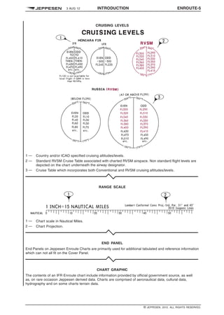
CRUISING LEVEL — A level maintained during a sig-
nificant portion of a flight.
CURRENT FLIGHT PLAN (CPL) — The flight plan,
including changes, if any, brought about by subse-
quent clearances.
DANGER AREA (ICAO) — [see SPECIAL USE
AIRSPACE (SUA)].
DATA CONVENTION — An agreed set of rules gov-
erning the manner or sequence in which a set of data
may be combined into a meaningful communication.
DATA LINK COMMUNICATIONS — A form of com-
munication intended for the exchange of messages
via a data link.
DATA LINK INITIATION CAPABILITY (DLIC) —
A data link application that provides the ability to
exchange addresses, names and version numbers
necessary to initiate data link applications.
DEAD RECKONING (DR) NAVIGATION — The esti-
mating or determining of position by advancing an
earlier known position by the application of direction,
time and speed data.
DECISION ALTITUDE (DA) or DECISION HEIGHT
(DH) (ICAO) — A specified altitude or height in
the precision approach or approach with vertical
guidance at which a missed approach must be initi-
ated if the required visual reference to continue the
approach has not been established.
NOTE:
a. Decision altitude (DA) is referenced to mean sea
level (MSL) and decision height (DH) is refer-
enced to the threshold elevation.
b. The required visual reference means that sec-
tion of the visual aids or of the approach area
which should have been in view for sufficient
time for the pilot to have made an assessment of
the aircraft position and rate of change of posi-
tion, in relation to the desired flight path. In Cat-
egory III operations with a decision height the
required visual reference is that specified for the
particular procedure and operation.
c. For convenience where both expressions are
used they may be written in the form “decision
altitude/height” and abbreviated “DA/H.”
DECISION ALTITUDE/HEIGHT (DA/H) (FAA) — Is
a specified altitude/height in an instrument approach
procedure at which the pilot must decide whether
to initiate an immediate missed approach if the pilot
does not see the required visual reference, or to
continue the approach. Decision altitude/height is
expressed in feet above mean sea level/ground level.
NOTE: Jeppesen approach charts use the abbrevia-
tion DA(H). The decision altitude “DA” is referenced to
mean sea level (MSL) and the parenthetical decision
height (DH) is referenced to the TDZE or threshold
elevation. A DA(H) of 1440ft (200ft is a Decision Alti-
tude of 1440ft and a Decision Height of 200ft.
DEPARTURE CLEARANCE VIA DATA LINK
(DCL) — Provides assistance for requesting and
delivering information and clearance, with the objec-
tive of reducing aircrew and controller workload. The
DCL service shall be initiated by the aircrew at a
suitable time between Ti and Tt where:
Ti – the earliest time at which a DCL service can
be initiated;
Tt – the latest time after which an aircrew, having
not completed the DCL service, is still able
to receive by voice procedures and in due
time, the vocal departure clearance.
The third time parameter of the DCL acknowledge
procedure is T1 where:
T1 – timer implemented in the ATS ground system
between the sending by ATS ground system
of the DCL clearance message and the
reception by it of the read-back of DCL
clearance message.
DEPENDENT PARALLEL APPROACHES — Simul-
taneous approaches to parallel or near-parallel
instrument runways where radar separation minima
between aircraft on adjacent extended runway centre
lines are prescribed.
DETRESFA — The code word used to designate a
distress phase.
DIRECT ROUTE - D1228763652000 — A requested route pub-
lished on a Jeppesen Enroute or Area chart to assist
pilots who have previous knowledge of acceptance
of these routes by ATC. Use of a Direct route may
require prior ATC approval and may not provide ATC
or Advisory services, or be acceptable in flight plans.
DISCRETE CODE — A four-digit SSR Code with the
last two digits not being “00.”
q$z
© JEPPESEN, 1984, 2015. ALL RIGHTS RESERVED.](https://image.slidesharecdn.com/glossary-legends-180225012312/85/Jeppesen-Glossary-legends-2016-21-320.jpg)
![14 INTRODUCTION 28 AUG 15
GLOSSARY q$i
based on satellite or other approach approved VNAV
systems. WAAS equipment may revert to this mode
of operation when the signal does not support “pre-
cision” or LPV integrity.
LEVEL — A generic term relating to the vertical
position of an aircraft in flight and meaning variously,
height, altitude or flight level.
LOCAL AIRPORT ADVISORY (LAA) — A service
provided by flight service stations or the military at
airports not serviced by an operating control tower.
This service consists of providing information to arriv-
ing and departing aircraft concerning wind direction
and speed, favored runway, altimeter setting, perti-
nent known traffic, pertinent known field conditions,
airport taxi routes and traffic patterns, and authorized
instrument approach procedures. This information is
advisory in nature and does not constitute an ATC
clearance.
LOCALIZER PERFORMANCE WITH VERTICAL
GUIDANCE (LPV) — Identifies the APV minimums
that incorporate electronic lateral and vertical guid-
ance. The lateral guidance is equivalent to localizer,
and the protected area is considerably smaller
than the protected area for the present LNAV and
LNAV/VNAV lateral protection. Aircraft can fly these
minimums with a statement in the Aircraft Flight Man-
ual (AFM) that the installed equipment supports LPV
approaches. This includes Class 3 and 4 TSO-C146
WAAS equipment, and future LAAS equipment. The
label LPV denotes minima lines associated with
APV-I or APV-II performance on approach charts.
LOCATION INDICATOR — A four-letter code group
formulated in accordance with rules prescribed by
ICAO and assigned to the location of an aeronauti-
cal fixed station.
LOW ALTITUDE AIRWAY STRUCTURE / FEDERAL
AIRWAYS (USA) — The network of airways serving
aircraft operations up to but not including 18,000ft
MSL.
LOW FREQUENCY (LF) — The frequency band
between 30 and 300kHz.
MAGNETIC VARIATION (VAR) — The orientation of
a horizontal magnetic compass with respect to true
north. Because there is a continuous small change of
direction of lines of magnetic force over the surface of
the earth, magnetic variation at most locations is not
constant over long periods of time.
MANDATORY ALTITUDE — An altitude depicted on
an instrument approach procedure chart requiring the
aircraft to maintain altitude at the depicted value.
MANDATORY FREQUENCY (MF) — A frequency
designated at selected airports that are uncontrolled
during certain hours only. Aircraft operating within
the designated MF Area, normally 5NM radius of the
airport, must be equipped with a functioning radio
capable of maintaining two-way communications.
Jeppesen charts list the MF frequency and the area
when other than the standard 5NM.
MANOEUVRING AREA — That part of an aero-
drome to be used for the take-off, landing and taxiing
of aircraft, excluding aprons.
MAXIMUM AUTHORIZED ALTITUDE (MAA) — A
published altitude representing the maximum usable
altitude or flight level for an airspace structure or route
segment.
MEDIUM FREQUENCY (MF) — The frequencies
between 300kHz and 3MHz.
METEOROLOGICAL AUTHORITY — The authority
providing or arranging for the provision of meteorolog-
ical service for international air navigation on behalf
of a Contracting State.
METEOROLOGICAL BULLETIN — A text compris-
ing meteorological information preceded by an appro-
priate heading.
METEOROLOGICAL INFORMATION — Meteo-
rological report, analysis, forecast, and any other
statement relating to existing or expected meteoro-
logical conditions.
METEOROLOGICAL OFFICE — An office desig-
nated to provide meteorological service for interna-
tional air navigation.
METEOROLOGICAL REPORT — A statement of
observed meteorological conditions related to a
specified time and location.
METEOROLOGICAL SATELLITE — An artificial
earth satellite making meteorological observations
and transmitting these observations to earth.
MILITARY OPERATIONS AREA (MOA) (USA) —
[see SPECIAL USE AIRSPACE (SUA)].
MINIMUM CROSSING ALTITUDE (MCA) — The
lowest altitude at certain fixes at which an aircraft
must cross when proceeding in the direction of a
higher minimum enroute IFR altitude (MEA).
MINIMUM DESCENT ALTITUDE (MDA) (FAA) —
Is the lowest altitude specified in an instrument
approach procedure, expressed in feet above mean
sea level, to which descent is authorized on final
approach or during circle-to-land maneuvering until
the pilot sees the required visual references for the
heliport or runway of intended landing.
MINIMUM DESCENT ALTITUDE (MDA) OR MINI-
MUM DESCENT HEIGHT (MDH) (ICAO) — A spec-
ified altitude or height in a non-precision approach or
circling approach below which descent must not be
made without the required visual reference.
NOTE 1: Minimum descent altitude (MDA) is refer-
enced to mean sea level and minimum descent height
(MDH) is referenced to the aerodrome elevation or to
the threshold elevation if that is more than 2m (7ft)
below the aerodrome elevation. A minimum descent
height for a circling approach is referenced to the
aerodrome elevation.
NOTE 2: The required visual reference means that
section of the visual aids or of the approach area
which should have been in view for sufficient time
for the pilot to have made an assessment of the air-
craft position and rate of change of position, in rela-
tion to the desired flight path. In the case of a circling
approach the required visual reference is the runway
environment.
NOTE 3: For convenience when both expressions
are used they may be written in the form “minimum
descent altitude/height” abbreviated “MDA/H.”
q$z
© JEPPESEN, 1984, 2015. ALL RIGHTS RESERVED.](https://image.slidesharecdn.com/glossary-legends-180225012312/85/Jeppesen-Glossary-legends-2016-27-320.jpg)
![16 INTRODUCTION 28 AUG 15
GLOSSARY q$i
NON PRECISION APPROACH (NPA) PROCE-
DURE — [see INSTRUMENT APPROACH PROCE-
DURE (IAP)]
NO PROCEDURE TURN (NoPT) — No procedure
turn is required nor authorized.
NORMAL OPERATING ZONE (NOZ) — Airspace
of defined dimensions extending to either side of
an ILS localizer course and/or MLS final approach
track. Only the inner half of the normal operating
zone is taken into account in independent parallel
approaches.
NOTAM (ICAO) — A notice distributed by means of
telecommunication containing information concern-
ing the establishment, condition or change in any
aeronautical facility, service, procedure or hazard, the
timely knowledge of which is essential to personnel
concerned with flight operations.
NO-TRANSGRESSION ZONE (NTZ) — In the con-
text of independent parallel approaches, a corridor
of airspace of defined dimensions located centrally
between the two extended runway centre lines, where
a penetration by an aircraft requires a controller inter-
vention to manoeuvre any threatened aircraft on the
adjacent approach.
OBSERVATION (METEOROLOGICAL) — The eval-
uation of one or more meteorological elements.
OBSTACLE ASSESSMENT SURFACE (OAS) — A
defined surface intended for the purpose of determin-
ing those obstacles to be considered in the calcula-
tion of obstacle clearance altitude/height for a specific
APV or precision approach procedure.
OBSTACLE CLEARANCE ALTITUDE (OCA) OR
OBSTACLE CLEARANCE HEIGHT (OCH) — The
lowest altitude or the lowest height above the ele-
vation of the relevant runway threshold or the aero-
drome elevation as applicable, used in establishing
compliance with appropriate obstacle clearance cri-
teria.
NOTE 1: Obstacle clearance altitude is referenced
to mean sea level and obstacle clearance height is
referenced to the threshold elevation or in the case
of non-precision approaches to the aerodrome ele-
vation or the threshold elevation if that is more than
7ft (2m) below the aerodrome elevation. An obstacle
clearance height for a circling approach is referenced
to the aerodrome elevation.
NOTE 2: For convenience when both expressions are
used they may be written in the form “obstacle clear-
ance altitude/height” and abbreviated “OCA/H.”
OBSTACLE FREE ZONE (OFZ) (ICAO) — The
airspace above the inner approach surface, inner
transitional surfaces, and balked landing surface and
that portion of the strip bounded by these surfaces,
which is not penetrated by any fixed obstacle other
than a low-mass and frangibly mounted one required
for air navigation purposes.
OBSTRUCTION CLEARANCE LIMIT (OCL) — The
height above aerodrome elevation below which the
minimum prescribed vertical clearance cannot be
maintained either on approach or in the event of a
missed approach.
OPERATIONAL CONTROL — The exercise of
authority over the initiation, continuation, diversion
or termination of a flight in the interest of the safety
of the aircraft and the regularity and efficiency of the
flight.
OPERATOR — A person, organization or enterprise
engaged in or offering to engage in an aircraft oper-
ation.
PILOT CONTROLLED LIGHTING (PCL) (USA) —
(For other states see Air Traffic Control Rules and
Procedures.)
Radio control of lighting is available at selected air-
ports to provide airborne control of lights by keying
the aircraft’s microphone. The control system con-
sists of a 3-step control responsive to 7, 5, and/or
3 microphone clicks. The 3-step and 2-step lighting
facilities can be altered in intensity. All lighting is illu-
minated for a period of 15min (except for 1-step and
2-step REILs which may be turned off by keying the
mike 5 or 3 times, respectively).
Suggested use is to always initially key the mike 7
times; this assures that all controlled lights are turned
on to the maximum available intensity. If desired,
adjustment can then be made, where the capability is
provided, to a lower intensity (or the REIL turned off)
by keying the mike 5 and/or three times. Approved
lighting systems may be activated by keying the mike
as indicated below:
KEY MIKE FUNCTION
7 times within 5
seconds
Highest intensity available
5 times within 5
seconds
Medium or lower intensity
(Lower REIL or REIL Off)
3 times within 5
seconds
Lowest intensity available
(Lower REIL or REIL Off)
Due to the close proximity of airports using the same
frequency, radio controlled lighting receivers may be
set at a low sensitivity requiring the aircraft to be rel-
atively close to activate the system. Consequently,
even when lights are on, always key mike as directed
when overflying an airport of intended landing or just
prior to entering the final segment of an approach.
This will assure the aircraft is close enough to acti-
vate the system and a full 15min lighting duration is
available.
PILOT-IN-COMMAND (PIC) — The pilot responsible
for the operation and safety of the aircraft during flight
time.
PITCH POINT — A fix/waypoint that serves as a tran-
sition point from a departure procedure or the low alti-
tude ground-based navigation structure into the high
altitude waypoint system.
POINT-IN-SPACE APPROACH (PinS) — The
point-in-space approach is based on a basic GNSS
non-precision approach procedure designed for
helicopters only. It is aligned with a reference point
located to permit subsequent flight manoeuvring or
approach and landing using visual manoeuvring in
adequate visual conditions to see and avoid obsta-
cles.
q$z
© JEPPESEN, 1984, 2015. ALL RIGHTS RESERVED.](https://image.slidesharecdn.com/glossary-legends-180225012312/85/Jeppesen-Glossary-legends-2016-29-320.jpg)
![28 AUG 15 INTRODUCTION 17
GLOSSARY q$i
POINT-IN-SPACE REFERENCE POINT (PRP) —
Reference point for the point-in-space approach as
identified by the latitude and longitude of the MAPt.
PRECISION APPROACH (PA) PROCEDURE —
[see INSTRUMENT APPROACH PROCEDURE
(IAP)].
PRECISION APPROACH RADAR (PAR) — Primary
radar equipment used to determine the position of
an aircraft during final approach, in terms of lateral
and vertical deviations relative to a nominal approach
path, and in range relative to touchdown.
NOTE: Precision approach radars are designated
to enable pilots of aircraft to be given guidance by
radio communication during the final stages of the
approach to land.
PRECISION OBJECT FREE ZONE (POFZ) (FAA)
— A volume of airspace above an area beginning
at the runway threshold, at the threshold elevation,
and entered on the extended runway centerline. The
standard POFZ is 200ft (60m) long and 800ft (240m)
wide. The POFZ must be kept clear when an air-
craft on a vertically guided final approach is within two
nautical miles (NM) of the runway threshold and the
reported ceiling is below 250ft and/or visibility less
than ¾ statute miles (SM) (or runway visual range
below 4000ft). The POFZ is considered clear even
if the wing of the aircraft holding on a taxiway wait-
ing for runway clearance penetrates the POFZ; how-
ever, neither the fuselage nor the tail may infringe
on the POFZ. For approaching aircraft, in the event
that a taxiing/parked aircraft or vehicle is not clear
of the POFZ, air traffic control will provide advisories
to the approaching aircraft regarding the position of
the offending aircraft/vehicle. In this case the pilot
of the approaching aircraft must decide to continue
or abort the approach. When the reported ceiling is
below 800ft or visibility less than 2SM, departing air-
craft must do the following. When there is an air traffic
control tower (ATCT) in operation, plan to hold at the
ILS hold line and hold as directed by air traffic control.
When there is no operating ATCT, honor the ILS hold
line and do not taxi into position and take-off if there
is an approaching aircraft within 2NM of the runway
threshold.
PRE-DEPARTURE CLEARANCE (PDC) — An
automated Clearance Delivery system relaying ATC
departure clearances from the FAA to the user net-
work computer for subsequent delivery to the cockpit
via ACARS (Airline/Aviation VHF data link) where
aircraft are appropriately equipped, or to gate print-
ers for pilot pickup.
PRESSURE ALTITUDE — An atmospheric pressure
expressed in terms of altitude which corresponds to
that pressure in the Standard Atmosphere.
PREVAILING VISIBILITY — The greatest visibility
value, observed in accordance with the definition “vis-
ibility”, which is reached within at least half the hori-
zon circle or within at least half of the surface of the
aerodrome. These areas could comprise contiguous
or non-contiguous sectors.
NOTE: This value may be assessed by human
observation and/or instrumented systems. When
instruments are installed, they are used to obtain the
best estimate of the prevailing visibility.
PRIMARY AREA — A defined area symmetrically
disposed about the nominal flight track in which
full obstacle clearance is provided. (See also SEC-
ONDARY AREA.)
PRIMARY RADAR — A radar system which uses
reflected radio signals.
PRIMARY SURVEILLANCE RADAR (PSR) — A
surveillance radar system which uses reflected radio
signals.
PROCEDURE ALTITUDE/HEIGHT — Are recom-
mended altitudes/heights developed in coordination
with Air Traffic Control requirements flown opera-
tionally at or above the minimum altitude/height and
established to accommodate a stabilized descent
at a prescribed descent gradient/angle in the inter-
mediate/final approach segment. Procedure alti-
tudes/heights are never below the Segment Minimum
Altitude (SMA) or Segment Minimum Safe Altitude
(SMSA).
PROCEDURE TURN (PT) (ICAO) — A maneuver in
which a turn is made away from a designated track
followed by a turn in the opposite direction to permit
the aircraft to intercept and proceed along the recip-
rocal of the designated track.
NOTE 1: Procedure turns are designated “left” or
“right” according to the direction of the initial turn.
NOTE 2: Procedure turns may be designated as
being made either in level flight or while descending,
according to the circumstances of each individual
procedure.
PROCEDURE TURN (PT) (USA) — The maneuver
prescribed when it is necessary to reverse direction
to establish an aircraft on the intermediate approach
segment or final approach course. The outbound
course, direction of turn, distance within which the
turn must be completed, and minimum altitude are
specified in the procedure. However, unless other-
wise restricted, the point at which the turn may be
commenced and the type and rate of turn are at the
discretion of the pilot.
PROCEDURE TURN INBOUND — That point of
a procedure turn maneuver where course reversal
has been completed and an aircraft is established
inbound on the intermediate approach segment or
final approach course. A report of “procedure turn
inbound” is normally used by ATC as a position report
for separation purposes.
PROFILE — The orthogonal projection of a flight path
or portion thereof on the vertical surface containing
the nominal track.
PROGNOSTIC CHART — A forecast of a specified
meteorological element(s) for a specified time or
period and a specified surface or portion of airspace,
depicted graphically on a chart.
PROHIBITED AREA (ICAO) (USA) — [see SPECIAL
USE AIRSPACE (SUA)].
QFE — [see ALTIMETER SETTING]
QNE — [see ALTIMETER SETTING]
QNH — [see ALTIMETER SETTING]
q$z
© JEPPESEN, 1984, 2015. ALL RIGHTS RESERVED.](https://image.slidesharecdn.com/glossary-legends-180225012312/85/Jeppesen-Glossary-legends-2016-30-320.jpg)
![18 INTRODUCTION 28 AUG 15
GLOSSARY q$i
RACETRACK PROCEDURE (ICAO) — A procedure
designed to enable the aircraft to reduce altitude dur-
ing the initial approach segment and/or establish the
aircraft inbound when the entry into a reversal proce-
dure is not practical.
RADAR — A radio detection device which provides
information on range, azimuth and/or elevation of
objects.
RADAR APPROACH — An approach, executed by
an aircraft, under the direction of a radar controller.
RADAR CONTACT — The situation which exists
when the radar position of a particular aircraft is seen
and identified on a radar display.
RADAR SEPARATION — The separation used
when aircraft position information is derived from
radar sources.
RADAR WEATHER ECHO INTENSITY LEVELS —
Existing radar systems cannot detect turbulence.
However, there is a direct correlation between
the degree of turbulence and other weather features
associated with thunderstorms and the radar weather
echo intensity. The National Weather Service has
categorized radar weather echo intensity for precip-
itation into six levels. These levels are sometimes
expressed during communications as “VIP LEVEL” 1
through 6 (derived from the component of the radar
that produces the information — Video Integrator
and Processor). The following list gives the “VIP
LEVELS” in relation to the precipitation intensity
within a thunderstorm:
Level 1.
Level 2.
Level 3.
Level 4.
Level 5.
Level 6.
WEAK
MODERATE
STRONG
VERY STRONG
INTENSE
EXTREME
RADIO ALTIMETER / RADAR ALTIMETER — Air-
craft equipment which makes use of the reflection of
radio waves from the ground to determine the height
of the aircraft above the surface.
RADIOTELEPHONY — A form of radio communica-
tion primarily intended for the exchange of information
in the form of speech.
RADIOTELEPHONY NETWORK — A group of
radiotelephony aeronautical stations which operate
on and guard frequencies from the same family and
which support each other in a defined manner to
ensure maximum dependability of air-ground com-
munications and dissemination of air-ground traffic.
REDUCED VERTICAL SEPARATION MINIMUMS
(RVSM) — A reduction in the vertical separation
between FL290 – FL410 from 2000ft to 1000ft.
REGIONAL AIR NAVIGATION AGREEMENT —
Agreement approved by the Council of ICAO nor-
mally on the advice of a regional air navigation
meeting.
REPETITIVE FLIGHT PLAN (RPL) — A flight plan
related to a series of frequently recurring, regularly
operated individual flights with identical basic fea-
tures, submitted by an operator for retention and
repetitive use by ATS units.
REPORTING POINT — A specified geographical
location in relation to which the position of an aircraft
can be reported.
REQUIRED NAVIGATION PERFORMANCE
(RNP) — A statement of navigation position accuracy
necessary for operation within a defined airspace.
RNP is performance-based and not dependent on a
specific piece of equipment. RNP includes a descrip-
tive number, the value being an indicator of the size
of the containment area (e.g., RNP-0.3, RNP-1,
RNP-3, etc.). The different values are assigned to
terminal, departure, and enroute operations. Some
aircraft have RNP approval in their AFM without a
GPS sensor. The lowest level of sensors that the FAA
will support for RNP service is DME/DME. However,
necessary DME signal may not be available at the
airport of intended operations. For those locations
having an RNAV chart published with LNAV/VNAV
minimums, a procedure note may be provided such
as "DME/DME RNP-0.3 NA." This means that RNP
aircraft dependent on DME/DME to achieve RNP-0.3
are not authorized to conduct this approach. Where
DME facility availability is a factor, the note may
read "DME/DME RNP-0.3 authorized; ABC and
XYZ required." This means that ABC and XYZ
facilities have been determined by flight inspection
to be required in the navigation solution to assure
RNP-0.3. VOR/DME updating must not be used for
approach procedures.
RESCUE COORDINATION CENTER — A unit
responsible for promoting efficient organization of
search and rescue service and for coordinating the
conduct of search and rescue operations within a
search and rescue region.
RESCUE UNIT — A unit composed of trained per-
sonnel and provided with equipment suitable for the
expeditious conduct of search and rescue.
RESTRICTED AREA (ICAO) (USA) — [see SPE-
CIAL USE AIRSPACE (SUA)].
REVERSAL PROCEDURE — A procedure designed
to enable aircraft to reverse direction during the initial
approach segment of an instrument approach proce-
dure. The sequence may include procedure turns or
base turns.
REVISION DATE — Charts revisions are issued on
Fridays. Charts are considered effective (usable)
upon receipt. With regard to the coverages, charts
are issued weekly or bi-weekly.
RNAV APPROACH — An instrument approach pro-
cedure which relies on aircraft area navigation equip-
ment for navigation guidance.
RNP TYPE — A containment value expressed as a
distance in nautical miles from the intended position
within which flights would be for at least 95 percent of
the total flying time.
EXAMPLE: RNP 4 represents a navigation accuracy
of plus or minus 7.4km (4NM) on a 95 percent con-
tainment basis.
q$z
© JEPPESEN, 1984, 2015. ALL RIGHTS RESERVED.](https://image.slidesharecdn.com/glossary-legends-180225012312/85/Jeppesen-Glossary-legends-2016-31-320.jpg)
![24 INTRODUCTION 28 AUG 15
GLOSSARY q$i
e. Runway Visual Range (RVR) — An instru-
mentally derived value, based on standard
calibrations, that represents the horizontal dis-
tance a pilot will see down the runway from
the approach end; it is based on the sighting
of either high intensity runway lights or on the
visual contrast of other targets whichever yields
the greater visual range. RVR, in contrast to
prevailing or runway visibility, is based on what
a pilot in a moving aircraft should see look-
ing down the runway. RVR is horizontal visual
range, not slant visual range. It is based on the
measurement of a transmissometer made near
the touchdown point of the instrument runway
and is reported in hundreds of feet. RVR is
used in lieu of RVV and/or prevailing visibility in
determining minimums for a particular runway.
1. Touchdown RVR — The RVR visibility
readout values obtained from RVR equip-
ment serving the runway touchdown zone.
2. Mid-RVR — The RVR readout values
obtained from RVR equipment located
midfield of the runway.
3. Rollout RVR — The RVR readout values
obtained from RVR equipment located
nearest the rollout end of the runway.
VISUAL APPROACH (ICAO) — An approach by
an IFR flight when either part or all of an instru-
ment approach procedure is not completed and the
approach is executed in visual reference to terrain.
VISUAL APPROACH (USA) — An approach con-
ducted on an instrument flight rules (IFR) flight plan
which authorizes the pilot to proceed visually and
clear of clouds to the airport. The pilot must, at all
times, have either the airport or the preceding aircraft
in sight. This approach must be authorized and under
the control of the appropriate air traffic control facility.
Reported weather at the airport must be ceiling at or
above 1000ft and visibility of 3 miles or greater.
VISUAL DESCENT POINT (VDP) — A defined point
on the final approach course of a non-precision
straight-in approach procedure from which normal
descent from the MDA to the runway touchdown
point may be commenced, provided the approach
threshold of that runway, or approach lights, or other
markings identifiable with the approach end of that
runway are clearly visible to the pilot.
VISUAL MANOEUVRING (CIRCLING) AREA —
The area in which obstacle clearance should be
taken into consideration for aircraft carrying out a
circling approach.
VISUAL METEOROLOGICAL CONDITIONS
(VMC) — Meteorological conditions expressed in
terms of visibility, distance from cloud, and ceiling
equal to or better than specified minima.
NOTE: The specified minima are contained in ICAO
Rules of the Air, Annex 2, Chapter 4.
VOLMET BROADCAST — Routine broadcast of
meteorological information for aircraft in flight.
VOLCANIC ASH ADVISORY CENTRE (VAAC) — A
meteorological centre designated by regional air nav-
igation agreement to provide advisory information to
meteorological watch offices, area control centres,
flight information centres, world area forecast cen-
tres, relevant regional area forecast centres and inter-
national OPMET data banks regarding the lateral and
vertical extent and forecast movement of volcanic ash
in the atmosphere following volcanic eruptions.
VOLMET BROADCAST — Provision of current
aerodrome meteorological reports (METAR) and
special meteorological reports (SPECI), aerodrome
forecasts (TAF), SIGMET by means of continuous
and repetitive voice broadcasts for aircraft in flight.
VOLMET DATA LINK SERVICE (D-VOLMET) —
Provision of current METAR, SPECI, TAF, SIGMET,
special air-reports not covered by SIGMET and,
where available, AIRMET via data link.
WARNING AREA (USA) — [see SPECIAL USE
AIRSPACE (SUA)].
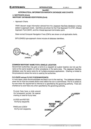
WAYPOINT — A specified geographical location
used to define an area navigation route or the flight
path of an aircraft employing area navigation. Way-
points are identified as either:
Fly-by waypoint — A fly-by waypoint requires the
use of turn anticipation to avoid overshoot of the
next flight segment; or
Fly-over waypoint — A fly-over waypoint pre-
cludes any turn until the waypoint is overflown
and is followed by an intercept maneuver of the
next flight segment.
WEATHER SYSTEMS PROCESSOR (WSP) —
An add-on weather processor to selected Airport
Surveillance Radar (ASR)-9 facilities that adds
Doppler weather radar capability and provides wind
shear and microburst warnings. The system gives
controllers timely and accurate warnings for relaying
to pilots via radio communications. The WSP also
provides controllers with thunderstorm cell locations
and movement as well as the predicted future posi-
tion and intensity of wind shifts that may affect airport
operations. The system can also process precipi-
tation data to reduce false severe weather reports
caused by anomalous propagation.
WIDE AREA AUGMENTATION SYSTEM (WAAS) —
WAAS is a navigation system developed for civil avi-
ation that provides extremely accurate horizontal
and vertical navigation for all classes of aircraft in
all phases of flight - including enroute navigation,
airport departures, and airport arrivals. This includes
vertically-guided landing approaches in instrument
meteorological conditions at all qualified locations.
WORLD AREA FORECAST CENTRE (WAFC) —
A meteorological centre designated to prepare and
issue significant weather forecasts and upper-air fore-
casts in digital and/or pictorial form on a global basis
direct States by appropriate means as part of the
aeronautical fixed service.
WORLD AREA FORECAST SYSTEM (WAFS) —
A world-wide system by which world area forecast
centres provide aeronautical meteorological en-route
forecasts in uniform standardized formats.
q$z
© JEPPESEN, 1984, 2015. ALL RIGHTS RESERVED.](https://image.slidesharecdn.com/glossary-legends-180225012312/85/Jeppesen-Glossary-legends-2016-37-320.jpg)
![26 FEB 16 INTRODUCTION 43
ABBREVIATIONS USED IN AIRWAY MANUAL q$i
DP Obstacle Departure Procedure
DRCO Dial-up Remote Communications
Outlet
E East or Eastern
EAT Expected Approach Time
ECOMS Jeppesen Explanation of Common
Minimum Specifications
EDT Eastern Daylight Time
EET Estimated Elapsed Time
EFAS Enroute Flight Advisory Service
EFF Effective
EFVS Enhanced Flight Vision System
EGNOS European Geostationary
Navigation Overlay Services
EH Eastern Hemisphere
ELEV Elevation
EMAS Engineered Materials Arresting
System
EMERG Emergency
ENG Engine
EOBT Estimated Off Block Time
EST Eastern Standard Time
EST Estimated
ETA Estimated Time of Arrival
ETD Estimated Time of Departure
ETE Estimated Time Enroute
ETOPS Extended Range Operation with
two-engine airplanes
EVS Enhanced Vision System
FAA Federal Aviation Administration
FACF Final Approach Course Fix
FAF Final Approach Fix
FAIL Failure
FANS Future Air Navigation System
FAP Final Approach Point
FAR Federal Aviation Regulation
FAS DB Final Approach Segment Datablock
FAT Final Approach Track
FATO Final Approach and Take-off Area
FBL Light (to qualify icing, turbulence,
etc.)
FBO Fixed Based Operator
FCP Final Control Point
FIA Flight Information Area
FIC Flight Information Center
FIR Flight Information Region
FIS Flight Information Service
FL Flight Level (Altitude)
FLARES Flare Pots or Goosenecks
FLD Field
FLG Flashing
FLT Flight
FM Fan Marker
FMC Flight Management Computer
FMS Flight Management System
FOD Foreign Object Damage
FOM Flight Operation Manual
FPM Feet Per Minute
FPR Flight Planning Requirements
FRA Free Route Airspace
FREQ Frequency
FSS Flight Service Station
FT Feet
FTS Flexible Track System
G Guards only (radio frequencies)
GA General Aviation
GBAS Ground-Based Augmentation
System
GCA Ground Controlled Approach
(radar)
GCO Ground Communication Outlet
GEN General
GLONASS Global Orbiting Navigation Satellite
System
GLS Ground Based Augmentation
System [GBAS] Landing System
GMT Greenwich Mean Time
GND Ground Control
GND Surface of the Earth (either land
or water)
GNSS Global Navigation Satellite System
GP Glidepath
GPA Glidepath Angle
GPS Global Positioning System
GPWS Ground Proximity Warning System
GS Glide Slope
G/S Ground Speed
GWT Gross Weight
H Non-Directional Radio Beacon or
High Altitude
H24 24 Hour Service
HAA Height Above Airport
HALS High Approach Landing System
HAS Height Above Site
HAT Height Above Touchdown
HC Critical Height
HDG Heading
HF High Frequency (3-30 MHz)
HGS Head-up Guidance System
HI High (altitude)
HI High Intensity (lights)
HIALS High Intensity Approach Light
System
HIRL High Intensity Runway Edge Lights
HIRO High Intensity Runway Operations
q$z
© JEPPESEN, 1984, 2016. ALL RIGHTS RESERVED.](https://image.slidesharecdn.com/glossary-legends-180225012312/85/Jeppesen-Glossary-legends-2016-40-320.jpg)
![ENROUTE-8 INTRODUCTION 2 MAR 12 q$i
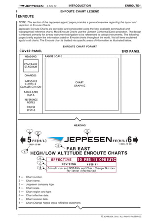
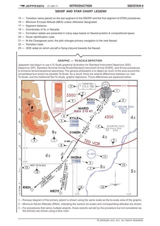
43 — Named or unnamed airspace fix or mileage break. Database identifiers are enclosed in square
brackets [ABROC]. They may be designated by the State (country) as Computer Navigation Fixes
(CNFs) or derived by Jeppesen. These identifiers should not be used in filing flight plans nor should
they be used when communicating with ATC; however they are also included in computer planning
systems. They are shown only to enable the pilot to maintain orientation when using charts in concert
with database navigation systems.
44 — Altitude Change.
45 — Route Minimum Off-Route Altitude (Route MORA).
46 — Direct Route (Requires ATC Approval, will not be accepted in Flight Plans).
47 — NDB.
48 — Communications related to Airport listed above Airport label. App/Arr, Dep, Twr and Gnd listed in Chart
tabulations. Asterisk indicates part time operation.
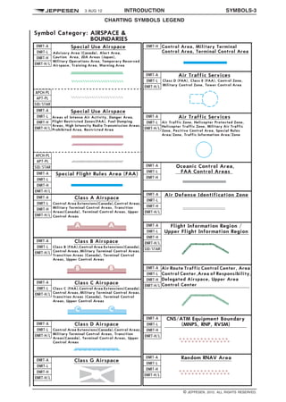
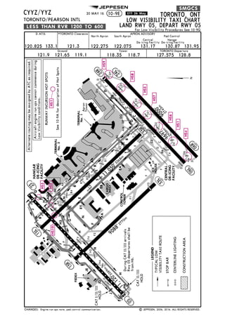
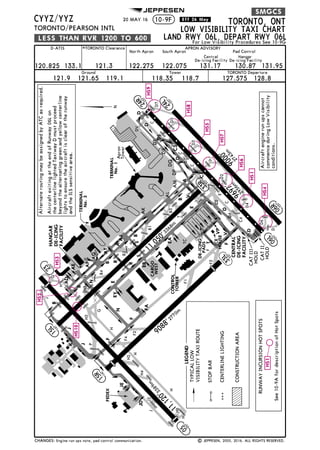
10–1B CHART LEGEND
10-1B charts depict the horizontal and vertical limits of Terminal airspace established by official source
publications and provide orientation details for flights operating within the area. Associated airport
communications are also included.
10-1B charts depicting US Class B airspace also includes general IFR and VFR Flight Procedures
appropriate to that particular area.
SAMPLE 10–1B CONTENT
1329508730203
q$z
© JEPPESEN, 2012. ALL RIGHTS RESERVED.](https://image.slidesharecdn.com/glossary-legends-180225012312/85/Jeppesen-Glossary-legends-2016-63-320.jpg)

![INTRODUCTION 207
Nav2001
AERONAUTICAL INFORMATION NAVDATA DATABASE AND CHARTS
©JEPPESEN SANDERSON, INC., 2001. ALL RIGHTS RESERVED.
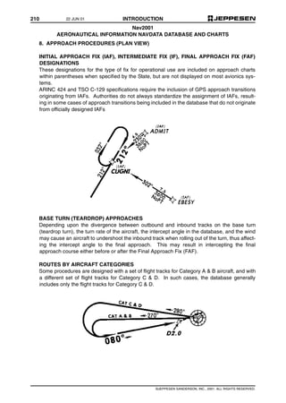
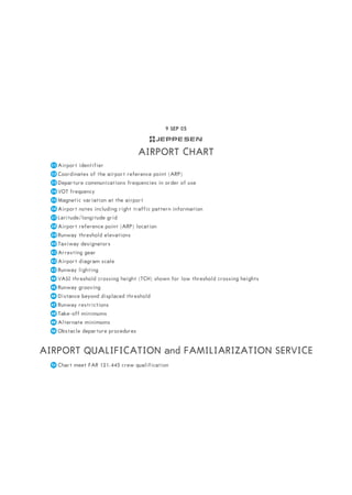
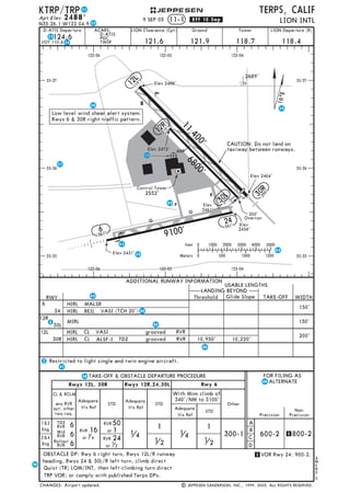
6. ARRIVALS AND DEPARTURES
PROCEDURES NOT IN THE DATABASE
Jeppesen publishes some officially designated departure procedures that include only text on
IFR airport charts beneath the take-off minimums. They may be labeled "Departure Proce-
dure", "IFR Departure Procedure", or "Obstacle DP". Most of these are U.S. and Canadian
procedures, although there is a scattering of them throughout the world. Any waypoint/fix
mentioned in the text is in the Jeppesen NavData database. However, these text-only depar-
ture procedures are not in the database.
Some States publish narrative descriptions of their arrivals, and depict them on their enroute
charts. They are unnamed, not identified as arrival routes, and are not included in the Jeppe-
sen NavData database. Some States publish "DME or GPS Arrivals", and because they are
otherwise unnamed, they are not included in the database.
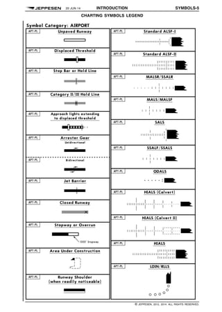
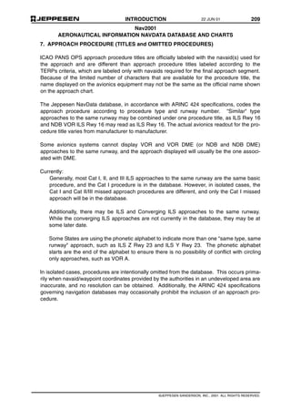
PROCEDURE TITLES
Procedure identifiers for routes such as STARs, DPs and SIDs are in airborne databases but
are limited to not more than six alpha/numeric characters. The database generally uses the
charted computer code (shown enclosed within parentheses on the chart) for the procedure
title, as
When no computer code is assigned, the name is truncated to not more than six characters.
The database procedure identifier is created according to the ARINC 424 specifications.
Database procedure identifiers are charted in most cases. They are the same as the
assigned computer code (charted within parentheses) or are being added [enclosed within
square brackets]. Do not confuse the bracketed database identifier with the official procedure
name (which will be used by ATC) or the official computer code (which is used in flight plan fil-
ing).
400-FOOT CLIMBS
Virtually all departures in the database include a climb to 400 feet above the airport prior to
turning because of requirements in State regulations and recommendations. The 400-foot
climb is not depicted on most charts. When States specify a height other than 400 feet, it will
be in the Jeppesen NavData database.
CHART:
DATABASE
Cyote Four Departure(CYOTE.CYOTE4) becomes
CYOTE4.
22 JUN 01](https://image.slidesharecdn.com/glossary-legends-180225012312/85/Jeppesen-Glossary-legends-2016-100-320.jpg)

This document discusses Jeppesen's methods of communicating updates and changes regarding their navigation products and services. It outlines several types of notices and alerts used to disseminate different types of time-critical information to subscribers. These include NavData Alerts for commercial subscribers, Chart Alerts for paper/electronic charts, and Airport Moving Map Alerts. It also discusses weekly NavData Change Notices and Chart Change Notices posted online and through RSS feeds. All communications are intended to supplement official NOTAMs and ensure safe flight operations using up-to-date Jeppesen data and procedures.


