Download to read offline
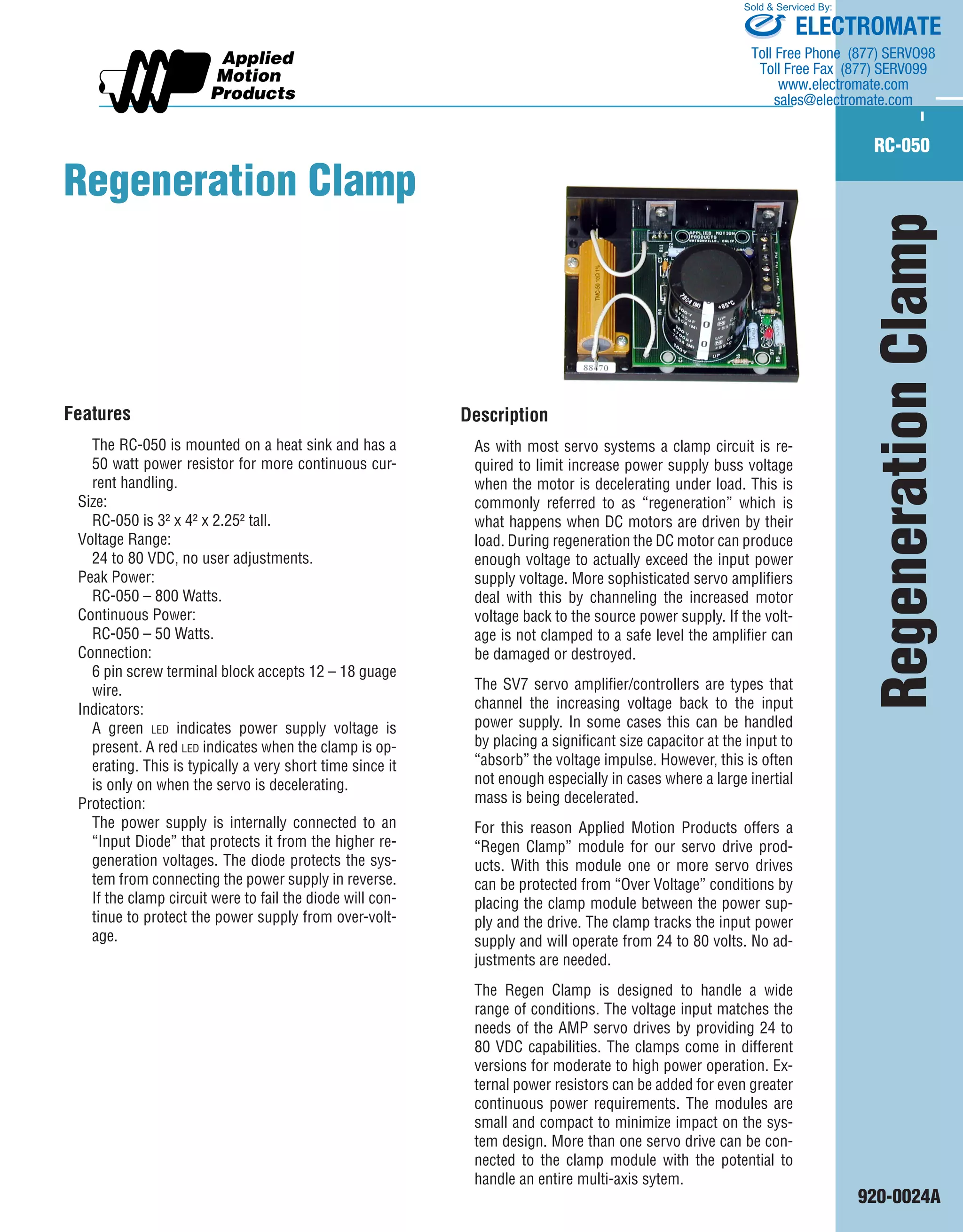

The document describes a regeneration clamp module that is used to protect servo drives from over voltage conditions during regeneration. The regeneration clamp tracks the input power supply voltage and limits it to safe levels when the motor voltage exceeds it due to deceleration under load. It comes in different versions for various power requirements and handles regeneration from one or multiple servo drives connected to an entire multi-axis system.


