Download to read offline

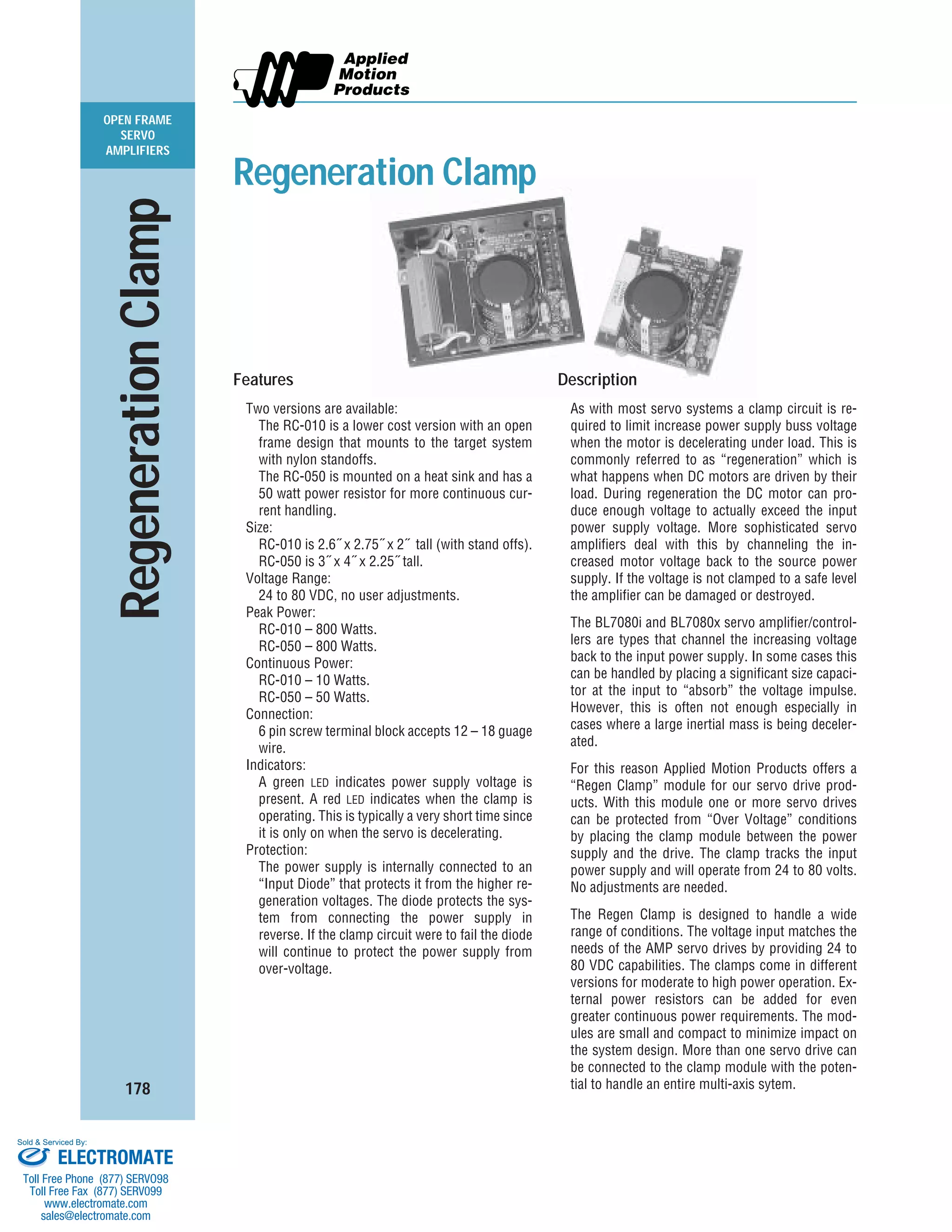

The document describes regeneration clamp modules that protect servo drives and power supplies from overvoltage conditions during motor deceleration. The modules have two versions - the RC-010 with a lower power rating and open frame design, and the RC-050 with a higher 50 watt power resistor and heat sink. Both clamp the voltage between 24-80VDC and have LED indicators and terminal blocks for easy installation. The clamps channel excess voltage from the motor back to the power supply during regeneration to prevent damage.