2. 2 R.Agbebi et al.
performance of the various controllers can be compared and an algorithm to switch
between the various controllers for particular process conditions.
2. Process Model Description
The first phase in the reactor involves heating, inflow of steam to achieve a desired
temperature set-point. The reaction phase starts at the desired temperature where
reagents are added, this result to an exothermic reaction which requires cooling, and
then the cooling phase starts with inflow of cooling water (Singh et al. 2010). The
temperature control performance mainly depends on the heating-cooling system
associated with the reactor. The different configurations of heating-cooling systems
cited in literature can be classified into two types: multifluid and monofluid systems
(Louleh et al.1999). The commercial reactor modeled in this study has a multifluid
system where steam is used as heating medium and water used as a cooling medium as
shown in the figure 1 below. The transfer of heat energy to and from the jacket and the
reactor is achieved with the transfer fluid through the wall of the reactor. Two
exothermic chemical reactions were modelled in the reactor;
Dissolution of Ruthenium
( ) ( ) (1)
Evaporation of Ruthenium Chloride
( ) ( ) ( )
( ) ( ) ( )
( ) (2)
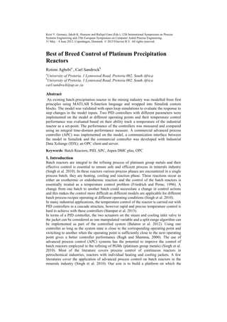
The model was developed in an explicit
formulation using MATLAB s-function
which could be used directly in custom
blocks in SIMULINK in pursuit of
getting the reactor model to interact
effectively with external platform
i.e. commercial controllers Figure 1: Reactor Model Description
3. PID Control
The process operating conditions are different from phase to phase and also from batch
to batch. As such, a requirement on the controller is that it regulates the plant at each
operating point or regime. The reactor temperature control is dependent on the control
of the steam valve and the cooling water valve of a reactor with a single jacket.
For this design requirement to be correctly modeled using a PID Controller, a split-
range algorithm was implemented. The split-range algorithm is preferred in the control
of cascaded reactor, to operate two actuators which control the inflow of utilities at the
different times during the different phases of a single batch (Balaton et al. 2012).
The two actuators on the steam and cooling water inflow valve to the jacket were
considered as one manipulated variable (MV) and the temperature of the reactor as the
controlled variable (CV). The PID controllers perform better on operating points they
were tuned on. The performance of PIDs degrades with change in process regimes and
operating points (Singh et al. 2010). Two PID controllers with different controller
3. Best of breed control of platinum precipitation reactors
parameters and set points were implemented on the SIMULINK model at different
model operating points.
4. Control Objective and Performance Measure
The controller design objective was its set-point tracking ability; its performance can be
measured with several integral time-domain performance measures. They are Integral of
the Square of the Error (ISE), the Integral of the Absolute value of the Error (IAE), and
the Integral of the time-weighted Absolute Error (ITAE).
∫ ( ) (3)
Where f (t) is a function of ϵ(t) = ysp(t) – y(t)
These were all implemented in the performance block of the Simulink model; however
the Integral of the Square of the Error (ISE) was used to evaluate the performance of the
controllers.
5. Advanced Process Control.
A commercial MPC controller called DMCplus; which is a multivariable controller
from AspenTech was developed to control the temperature of the reactor model in
Simulink. The DMCplus controller implemented in this work has two manipulated
variables (steam and cooling water valves to the same reactor jacket), no feed forward
variables and one controlled variable (reactor temperature). As both manipulated
variables use the same jacket, they cannot be used at the same time. The controller
executes periodically in cycles, the following steps were followed in developing the
controller;
Configuration of MVs and CV tags using Aspen DMC plus Build
Calculate the open loop prediction for the controlled variable based on step
change in manipulated variables which is the model development
Steady State Simulation using Aspen DMC plus Model
Determine the path by which the manipulated variables move from their
current positions to the end positions i.e. the move plan of the controller.
Prediction and Tuning of Controller using ASPEN APC web Interface
5.1 Model Interaction with external platforms.
The communication between the Simulink model and the commercial controller shown
in figure 2 is very important and this was achieved using MATLAB OPC toolbox and
Industrial Data Xchange (IDX); an OPC client and server. The IDX makes the outputs
and inputs of the Simulink model available to the ASPEN DMC plus as data tags
through the Aspen Cim-IO.The Aspen Cim-IO is an interface solution for AspenTech
systems.
ST
CW
Reactor Model
Figure 2 : Simulink model interaction with commercial controller
ASPEN DMC Plus
OPC
READ
BLOCK
OPC
WRITE
BLOCK
IDX OPC
SERVER
ASPEN
CIM-O
4. 4 R.Agbebi et al.
Figure 3 shows the IDX
OPC client interface
with the MVs and CVs
data communication
between the Simulink
model and commercial
controller.
Figure 3: IDX OPC Client
Figure 4: ASPEN APC Web Interface
Figure 4 shows the independent and dependent variables of the controller configuration
developed using Aspen DMC plus Build, and monitored on the APC Web Interface.
A controller model was built using the Aspen DMC plus Model, the open loop
prediction of the model is shown in figure 5. This shows a test controller with cooling
phase; increase in cooling water and decrease in steam.
Figure 5: Open Loop Simulation.
Figure 6 shows a closed loop test simulation of the model, the response of the CV to
predicted moves of the MVs; this validates the communication between the variables.
5. Best of breed control of platinum precipitation reactors
Figure 6: Closed Loop Simulation Response
6. Results and Discussion
The Simulink model was linearized to obtain linear time-invariant state-space models at
two different steady state operating points, open loop simulations were ran on two the
models and closed loop models were developed using Simulink PID compensator
design tool.
The open loop response of the reactor temperature to a step change in the inflow of
utilities; steam inflow for heating and cooling water inflow for cooling was done. This
validates the response of the model to a unit step change in input at set utility
temperatures which are cooling water at 278K and steam at 400.15K.
The closed loop performance results of the PID controllers show the model reactor
tracking the set point temperature which is the plant temperature data.
Figure 10: Simulation results of PID 1 on model 1 Figure 11: Simulation with PID 2 on model 1
Figure 10 and Figure 11 shows closed loop simulation using using temperature from
plant data as PID set point. In Figure 10, PID controller 1 tuned on model 1 shows a
very good set-point tracking performance with a lower integral square error of 5.995.
6. 6 R.Agbebi et al.
In Figure 11, PID controller 2 tuned on model 1 shows a bad set-point tracking
performance with a higher integral square error of 132.62.
Table 1 shows different operating point of the linearized state-space models and Table 2
shows the performance of different controllers implemented on different models using
temperature from plant data as reference temperature. The PID 1 performed better on
model 1 and PID 2 performed better on model 2
Table 1: Model operating points Table 2: Controller Performance Values
7. Further Work
The Advanced Process Controller (APC) implemented on the reactor model will be
tuned to its best performance and the performance will be compared to that of the PID
controllers and a combination of controllers will be implemented on the model in order
to assess if the hybrid controller will out-perform a single controller.
8. Conclusions
PID controllers perform better on model operating points there were tuned on with a
lower integral square error (ISE) and their performance degrades with change in process
operating points and batches (Noguchi and Kobari, 2005). To overcome these
limitations, a commercial APC (Aspen DMC Plus) which has been successfully
connected to the Simulink model will be tuned and completely implemented to validate
(Singh et al. 2010)’s work on the actual commercial reactors which proves that the APC
controller out-performs PID controller. The platform needed to compare ability of the
PID and the APC control system with the reactor model is now developed.
9. References
M.G. Balaton, L. Nagy, F. Szeifert, 2012, Model-Based Split-Range Algorithm for the
Temperature Control of a Batch Reactor. Scientific Research Eng, 4, 515-525
M. Friedrich and R. Perne, 1995, Design and Control of Batch Reactors - An Industrial
Viewpoint, Comp & Chem Eng, 19, S357-S368.
Z. Louleh, M. Cabassud, M.V. Le Lann, 1999, A New Strategy for Temperature Control
of Batch Reactors: Experimental Application, Chem Eng Jour 75, 1, 11-20.
Y. Noguchi and M. Kobari, 2005, Model Predictive Control with single heat transfer
fluid for Batch Reactor temperature control, SICE Annual Conference, 449 – 452
W. J. Rugh and J. S. Shamma, 2000, Research on gain scheduling, Automatica, 36,
1401 – 1425
A. Singh, P.G.R. De Villiers, P. Rambalee, G. Gous, J. De Klerk, Humphries G. , 2010,
A Holistic approach to the application of Model Predictive Control to batch reactor,
Automation in Mining, Mineral and Metal Processing, 13, 172-132
S. Stampar and S. Somkolic, 2013, Nonlinear Control of Hybrid Batch Reactor, Journal
of Mech Eng , 59, 112 – 123
Controller Model
Integral Square
of Error (ISE)
PID 1 1 5.995
PID 1 2 87.61
PID 2 1 132.62
PID 2 2 7.993
Operating Points Model 1
Model
2
Reactor
Temperature (K)
303.1040 292.1161
Jacket
Temperature (K)
304.1142 299.0432