Download to read offline
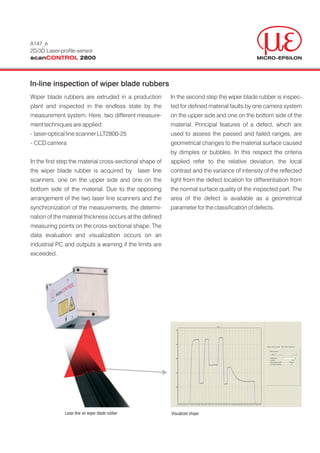
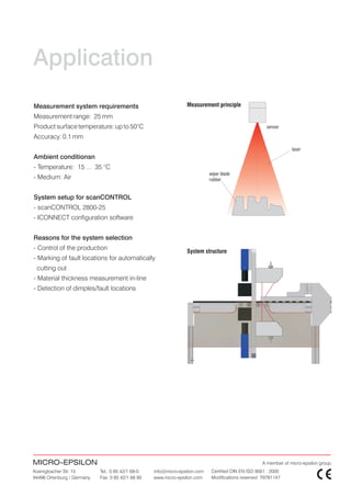

The document describes an in-line inspection system for measuring wiper blade rubbers using a laser line scanner and cameras. The system uses two laser scanners on the top and bottom of the material to measure the thickness and cross-sectional shape. Cameras on both sides inspect for defects like dimples or bubbles based on surface deviations, contrast, and intensity variance. The system provides thickness measurements, marks defect locations, and outputs warnings if measurement limits are exceeded to control production quality.


