App099 en thickness-measurement-battery-separators
1. A99_e
Non-Contact thickness measurement
dimensionCONTROL
Thickness measurement of battery separators
In the production of battery separators the in-line Measurement system structure, mechanical
monitoring of the profile thickness is an important - Welded C-frame, supported on air bearings on a
measurement task within the framework of quality hard rock base, dimensions approx. 2434 x 2000 x
assurance. A measurement system with high spatial 632 mm, weight approx. 1500 kg.
resolution and a high sampling rate is needed for the - 4-point air bearing with individual pressure
determination of the profile structure. This task monitoring (flight height 6 µm) max. travel 1040 mm.
represents one of the classical fields of application
for the laser-based triangulation sensor in the Series Measurement system structure, sensors
ILD 2000. The battery separator is manufactured in - 2 pcs. ILD 2000-10.15 Laser-based optical
an extrusion process. For the thickness displacement sensor.
measurement the optical sensors are mounted on a - 2 pcs. U15 Eddy-current displacement sensor with
welded C-frame. This traverses on air bearings DT 110 single-channel electronics.
without making physical contact on a hard rock base. - 1 pc. WDS 1500-P60 CR-E Draw-wire displacement
In this way the vibration of the top belt is minimized sensor.
and a precise measurement facilitated. The thermal
changes of the frame are monitored with eddy
current sensors and compensated by computation.
Special cleaning mechanisms ensure the
ruggedness of the system in a harsh industrial
environment. PC software processes and analyses
the measurement data and computes the thickness
values.
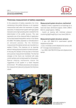
In-line quality monitoring in a
direct production line.
2. Application
Measurement system structure, software
- Application produced with graphical development
environment ICONNECT.
- Extent, approx. 500 modules structured with
macros.
- 3 concurrent signal graphs.
- Win NT 4.0 operating system.
Measurement system requirements
Software:
Routine measurement: Fig. 1 Visual display of lateral profile.
- Measurement data acquisition and visual display
(see Fig. 1).
- Display of trends of the individual zones.
- Traversing control.
- Calculation of the measured quantity.
- Archiving of the measurement data.
- Data transfer to the parameter data base.
- Production of a measurement log.
Setup mode:
- Measurement data acquisition (see Fig. 2).
- Positioning of the C-frame.
- System calibration.
Fig. 2 Visual display in setup mode.
Parameter data base:
- Linking to a FoxPro data base: via a flexible SQL
interface.
Sensors:
- Measurement range: 10 mm
- System accuracy: ±0.025 mm
- Reproducibility : 0.4 µm
MICRO-EPSILON A member of micro-epsilon group.
Koenigbacher Str. 15 Tel.: 0 85 42/1 68-0 info@micro-epsilon.com Certified DIN EN ISO 9001 : 2000
94496 Ortenburg / Germany Fax: 0 85 42/1 68 90 www.micro-epsilon.com Modifications reserved Y9781099