Download to read offline
![57 Anti missile diffusion system through MATLAB with Image Processing
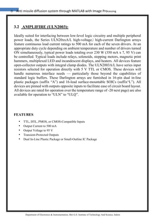
Department of Electronics & Instrumentation, Shri G.S. Institute of Technology And Science, Indore
4.3 The RGB color model is an additive color model in which red, green, and blue
light are added together in various ways to reproduce a broad array of colors. The name
of the model comes from the initials of the three additive primary colors , red, green,
and blue.
The main purpose of the RGB color model is for the sensing, representation, and display
of images in electronic systems, such as televisions and computers, though it has also
been used in conventional photography. Before the electronic age, the RGB color model
already had a solid theory behind it, based in human perception of colors.
Typical RGB input devices are color TV and video cameras, image scanners, and digital
cameras. Typical RGB output devices are TV sets of various technologies (CRT, LCD,
plasma, etc.), computer and mobile phone displays, video projectors, multicolor LED
displays, and large screens as JumboTron, etc. Color printers, on the other hand, are not
RGB devices, but subtractive color devices (typically CMYK color model). This article
discusses concepts common to all the different color spaces that use the RGB color
model, which are used in one implementation or another in color image-producing
technology.
To form a color with RGB, three colored light beams (one red, one green, and one blue)
must be superimposed (for example by emission from a black screen, or by reflection
from a white screen). Each of the three beams is called a component of that color, and
each of them can have an arbitrary intensity, from fully off to fully on, in the mixture.
The RGB color model is additive in the sense that the three light beams are added
together, and their light spectra add, wavelength for wavelength, to make the final
color's spectrum.[1][2]
Zero intensity for each component gives the darkest color (no light, considered the
black), and full intensity of each gives a white; the quality of this white depends on the
nature of the primary light sources, but if they are properly balanced, the result is a](https://image.slidesharecdn.com/3-180321055535/85/Anti-missile-diffusion-system-through-MATLAB-with-Image-Processing-57-320.jpg)
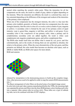
![60 Anti missile diffusion system through MATLAB with Image Processing
Department of Electronics & Instrumentation, Shri G.S. Institute of Technology And Science, Indore
4.4 GREY
Grey (international and some parts of the U.S.) or gray (some U.S. only – see spelling
differences) describes the tints and shades ranging from black to white. These, including
white and black, are known as achromatic colors or neutral colors. In recent years,
"neutral colors" had been reclassified. These "new" neutrals have low colorfulness
and/or chroma on the color wheel.
Greys are seen commonly in nature and fashion. Grey paints can be created by mixing
complementary colors (that is colors directly opposite on the color wheel, e.g. yellow
and violet). In the RGB color model used by computer displays, it is created by mixing
equal amounts of red, green, and blue light. Images which consist wholly of neutral
colors are called monochrome, black-and-white or greyscale.
Hex triplet #808080
sRGBB
(r, g, b) (128, 128, 128)
B: Normalized to [0–255] (byte)](https://image.slidesharecdn.com/3-180321055535/85/Anti-missile-diffusion-system-through-MATLAB-with-Image-Processing-60-320.jpg)
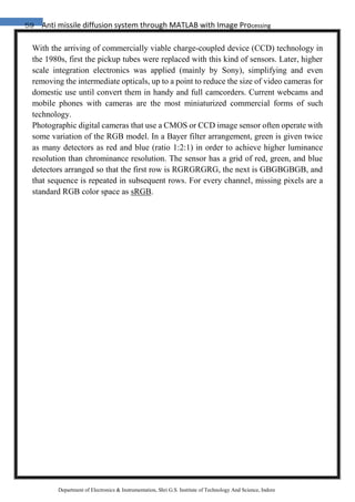
![66 Anti missile diffusion system through MATLAB with Image Processing
Department of Electronics & Instrumentation, Shri G.S. Institute of Technology And Science, Indore
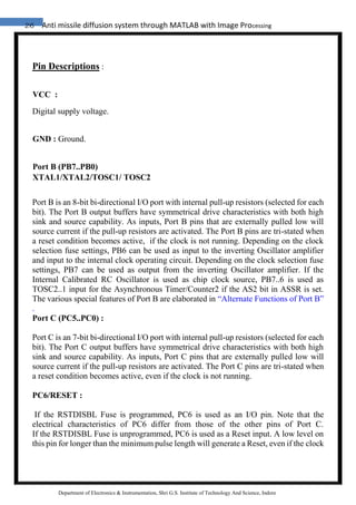
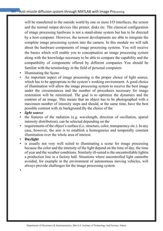
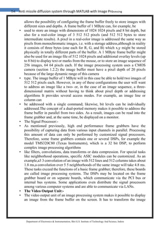
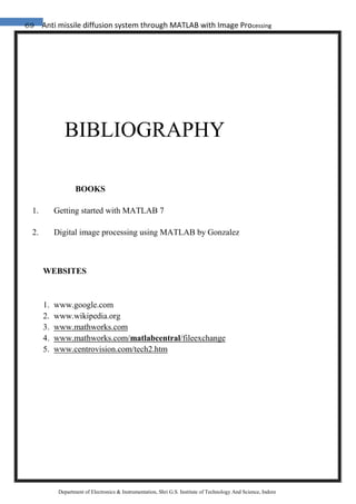
8. ALGORITHM FOR IMPLEMANTATION :
1) Initialize image input:
vid= videoinput (‘winvideo’ ,1 );
2) Initialize parallel port (input/output lines)
dio = digitalio('parallel','LPT1');
3) Declaration of variables
4) Get snapshot:
frame = getsnapshot (vid);
5) Locate the position of light.
6) Taking rgb colours as input & change in gray format
7) weight=(gray1(i,j)/256)^25+weight;
x=i*(gray1(i,j)/256)^25 +x;
y=j*(gray1(i,j)/256)^25 +y;
rgb1=double(rgb);
for i=-5:5;
for j=-5:5;
rgb_sum = rgb_sum + gray1(X+i,Y+j);
rgb1(X+i,Y+j,1)=256;
rgb1(X+i,Y+j,2)=0
rgb1(X+i,Y+j,3)=0
[a b intensity]=locate_light(frame);
display(intensity);
8) If intensity > reference value
9) then: light detected,
pause (0.1s)
else
light not detected: pause (0.1 s)
default set right turn;
end;](https://image.slidesharecdn.com/3-180321055535/85/Anti-missile-diffusion-system-through-MATLAB-with-Image-Processing-66-320.jpg)

The document discusses the development of an anti-missile diffusion system utilizing MATLAB and image processing technology to enhance human-robot interaction in industrial robotics. It highlights the use of webcams and various interfacing components, such as voltage regulators and encoder/decoder ICs, to create a dynamic camera system that improves real-time communication between robots and operators. Additionally, it covers practical applications of these technologies, emphasizing their importance in advancing robotics and control systems.