Download to read offline


![| 10Your Fixing Systems Specialist
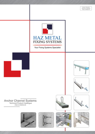
HMPR-CE Anchor Spacings & Minimum Edge Distances
Anchor Channel 28/15 38/17 40/25 & 40/22 49/30 & 50/30
50/30P40/22P & 40/26P 50/30P
54/33 & 52/34 72/49
Special screws M
[mm]
8 10 12 10 12 16 10 12 16 12 16 20 12 16 20 20 24 30
Min. spacing of screws Ss,min 40 50 60 50 60 80 50 60 80 60 80 60 80
Min. anchorage dept min hef 45 76 79 94 155 179
Min. edge distance Cmin 40 50 50 75 100 150
Min. member thickness hmin hef + Dh + Cnom
100 100 100 120 150
Anchor stud spacings
Side view
Plan view
Minimum edge distances
Depending on the type of the channels, anchors studs
must be positoned at a minimum distance from the
component edges.
The minimum spacings of the T head bolts must be
adhered to according to the table below.
In order to meet the resistance loads, anchor stud
spacings should be postitioned according to the tables
below.
28/15
Anchor
Channel
Anchor
Spacing
smin
(mm)
smax
round
anchor
round
anchor
End
Spacing (x)
Min Channel
Length
(mm l)
38/17
40/25
40/22
49/30
50/30
54/33
52/34
72/49
40/22P
50/30P
52/34P
40/26P
50
50
100
100
100
100
100
100
130
100
100
100
100
200
200
250
250
250
250
250
250
400
250
250
250
250
25
25
25
25
25
35
35
35
35
25
35
35
25
100
100
150
150
150
170
170
170
200
150
170
170
150
HMPRHMPR](https://image.slidesharecdn.com/haz-ci-en-200815120514/85/Anchor-Channel-Technical-Catalog-13-320.jpg)


![13
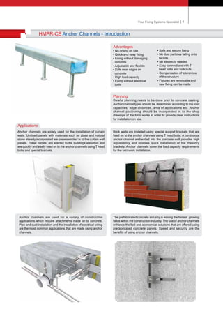
HMPR-CE Anchor Channels - Product Range
Dimensions of the HAZ METAL Special Screws & Strength Grade
Hammer-head screw
Fig. 1
Notch for marking
the position
Fig. 1
Hook-head
special screw
• The length of the T bolt must be
determined using the formula
l erf = Bolt length
i = channel lip thickness
s = washer thickness
V = minimum thread length
I erf
V
T Head
Bolt
1) Materials according to Annex 3, Table 1
Dimensions of the HAZ METAL Special Screws:
Anchor
Channel
Fig.
Dimensions Length
lb1 b2 k Ø
[mm] [mm]
28/15
1 10 23 4 8 15-200
1 10 23 5 10 20-300
38/17
1 13 31 6 8 20-300
1 13 31 6 10 20-300
1 13 31 7 12 20-300
1 13 31 7 16 20-300
40/22P
40/25
40/26P
2 14 35 7,5 10 20-300
2 14 35 7,5 12 20-300
2 14 34 8,5 16 20-300
49/30
50/30P
52/34P
54/33
2 13 43,3 10 10 20-300
2 13 43,3 10 12 20-300
2 17 43,3 11 16 20-300
2 21 43,3 12 20 30-300
72/49
2 23 58 14 20 50-300
2 25 58 16 24 50-300
2 31 58 20 30 50-300
Special Screws Steel 1) Stainless Steel 1)
Strength grade 4.6 8.8 A4-50 A4-70
fuk [N/mm2] 400 800 500 700
fyk [N/mm2] 240 640 210 450
Finish z.p., h.d.g
T head bolt
Metric size
Vmin (mm)
M8 12.5
M10 14.5
M12 17.0
M16 20.5
M20 26.0
M24 29.0
M30 33.5
Dimensions Vmin
Anchor
Channel
i (mm)
28/15 2.25
38/17 3.00
40/25 5.60
49/30 7.39
54/33 7.90
72/49 9.90
Dimensions of channel lip i](https://image.slidesharecdn.com/haz-ci-en-200815120514/85/Anchor-Channel-Technical-Catalog-16-320.jpg)


![| 16Your Fixing Systems Specialist
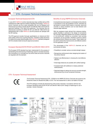
HMPR-CE Anchor Channels Technical Summary
hch
bch bch
hch
tnom,l
z
z
y y
f
d
tnom,b
d
z
z
y y
tnom,l
tnom,b
Cold rolled channel
f
d
bch
hch
z
z
y y
tnom,l
tnom,b
f
Hot rolled channel
Profiles
Section View
Material A2/A4/HDG
HS
72
20 24 30 12 16 20 12 16 20 10 12 16 10 12 16 8 10 12 12 16 20 12 16 20 10 12 16
100 120 150 60 80 100 60 80 100 50 60 80 50 60 80 40 50 60 60 80 100 60 80 100 50 60 80
A2/A4/HDG
HS/HAZ
50
A2/A4/HDG
HS/HAZ
50
A2/A4/HDG
HS/HAZ
40
A2/A4/HDG
HS/HAZ
38
A2/A4/HDG
HS/HAZ
28
HDG
HS/HAZ
50
HDG
HS/HAZ
50
HDG
HS/HAZ
40
45 / 50.5
45 / 50.5
41.7 / 36.6
41.7 / 36.6
17.2 / 25
17.2 / 25
12.5 / 15
12.5 / 15
10.5 / 12.2
10.5 / 12.2
7.2 / 8.3
7.2 / 8.3
29.77 / -
30.6 / -
17.67 / -
17.67 / -
12.61 / -
12.61 / -
9868
6408
2832
2696
1646
1600
1179
911.3
517.4
566.1
303.5
302.6
2440
-
2704
-
1261
72 54 49 40 38 28 52 50 40
49 33 30 25 17 15 34 30 22
182 157 96 81 78 47 158 96 78
179 155 94 79 76 45 156 94 76
150 100 75 50 50 40 100 75 50
-
Bolt Type
Bolt
M
HDG
St.St.
NRd,s,l
= NRd,s,c
[kN]
Steel / Stainless steel
VRd,s,l
[kN]
Steel / Stainless steel
MRd,s,flex
[Nm]
Design Resistance Capacities of Profiles (Design Values)
Geometric Values
Sslb
[mm]
bch
[mm]
hch
[mm]
hnom
[mm]
hef
[mm]
cmin
[mm]
HMPR
72/49
HMPR-CE
54/33
HMPR-CE
49/30
HMPR-CE
40/25
HMPR-CE
38/17
HMPR-CE
28/15
HMPR-H
52/34
HMPR-H
50/30
HMPR-H
40/22
Cold Rolled Channels Hot Rolled Channels
72
49
33
22
54
33
22
49
18
40
25 18
38
17
15
28
12
52
22
34
30
22
50
22
40
18](https://image.slidesharecdn.com/haz-ci-en-200815120514/85/Anchor-Channel-Technical-Catalog-19-320.jpg)
![17
HMPR Power Anchor Channels Technical Summary
tnom,l
Cold rolled channel
d
bch
hch
z
z
y y
tnom,b
d
bch
hch
z
z
y y
tnom,l
tnom,b
f
Hot rolled channel
Profiles
Section View
Material HDG HDG HDG A2/A4/HDG
HS HS/HAZ HS/HAZ HS/HAZ
50 50 40 40
60 80 100 60 80 100 50 60 80 50 60 80
12 16 20 12 16 20 10 12 16 10 12 16
28.66 / - 22.33 / - 13.22 / - 12.66 / 14.77
28.66 / -
2440 2704 1261 2440
- - - 911
52 50 40 40
34 30 22 25
158 108 93 96
155.5 106 91.2 94.2
100 75 50 50
22.33 / - 13.22 / - 12.77 / 15.00
Bolt Type
Bolt
M
HDG
St.St.
NRd,s,l
or NRd,s,c
[kN]
Steel / Stainless steel
VRd,s,c
or VRd,s,l
[kN]
Steel / Stainless steel
MRd,s,flex
[Nm]
Design Resistance Capacities of Profiles (Design Values)
Geometric Values
Sslb
[mm]
bch
[mm]
hch
[mm]
hnom
[mm]
hef
[mm]
cmin
[mm]
HMPR
52/34P
Hot Rolled Channels Cold Rolled Channels
HMPR
50/30P
HMPR
40/22P
HMPR-P
40/26
22
52
34
3022
50
22
40
18 18
40
25
f](https://image.slidesharecdn.com/haz-ci-en-200815120514/85/Anchor-Channel-Technical-Catalog-20-320.jpg)
![| 18Your Fixing Systems Specialist
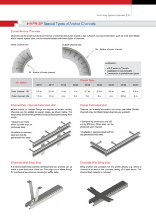
HMPR-P Anchor Channels Dynamic Loads
The fatigue resistance for loads with a load range where the lower limits of amplitude are equel to zero can be read directly from the S-N curve
according to ETA-09/0338 for any number of load cycles.
Fatigue resistance at lower limit of amplitude = 0
Fatigue resistance ∆NRd,0
[kN]
Combination of anchor channels and T-bolts for cyclic tensile stress
One sided fire exposure Multi-sided fire exposure
Characteristic resistance under tension and shear load under fire exposure
Fatigue resistance ∆NRd,0
[kN]
0
5
10
15
20
25
30
104
105
106
2 x 10⁶
2x10⁶
108
40/22P
50/30P
52/34P
40/26P St.St.
40/26P
Number of Load Cycles
40/22P
≤ 104
40/26P
Anchor Channel 28/15 38/17 72/49
40/25
40/22
40/22P
40/26P
49/30
50/30
50/30P
54/33
52/34
52/34P
40/22P
50/30P
52/34P
Profile
Profile T-Bolts
≤ 105
≤ 106
≤ 2 x 10⁶
≤ 2 x 10⁶
≤ 108
13.3
M12
Channel Bolts ≥
Partial safety factor
1) In absence of other national regulations
Steel failure: Anchor, connection channel/anchor, local flexure of channel lips
[mm]
[kN]
[-]
M12 M16 M16 M16 M16
0.9 1.8 1.8 5.7 5.7
0.7 1.5 1.5 4.2 4.2
0.5 1.2 1.2 2.6 2.6
0.4
R30
NRk,s,fi
VRk,s,fi
ɣRk,s,fi
=
R60
R90
R120
1.0
1.1 1.1 1.8 1.8
M12
M16
M16
8.8, A4
1)
8.8
8.8
8.8
6.6
3.1
2.7
2.4
2.3
8.2
2.7
1.2
1.1
1.1
1.1
18.1
9.4
5.3
4.8
4.5
4.2
26.6
15.6
9.1
8.2
7.5
7.0
12
4.2
1.8
1.7
1.6
1.6
40/26P 50/30P 52/34P 40/26P
St.St.
a
hef
≥ c min, fi
a a
a
Fire
attack
≥cmin,fi
FIRE EXPOSURE](https://image.slidesharecdn.com/haz-ci-en-200815120514/85/Anchor-Channel-Technical-Catalog-21-320.jpg)


The document is a technical product catalogue for Haz Metal A.S., focusing on their anchor channel systems used in facade construction. It details product specifications, production capabilities, quality standards, and various applications of anchor channels, emphasizing their compliance with European technical assessments and quality management systems. Additionally, the catalogue outlines the manufacturing processes, design methodologies, and advantages of using their fixing systems in construction projects.


