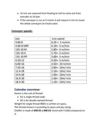
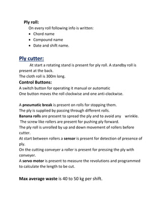
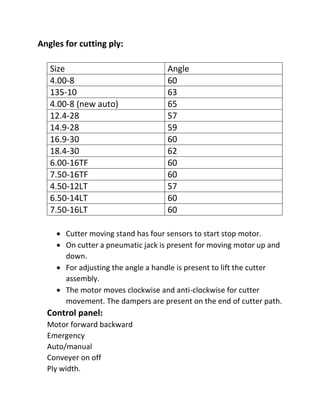
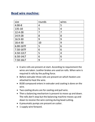
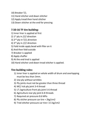
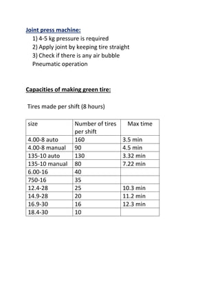
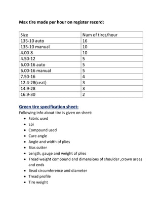
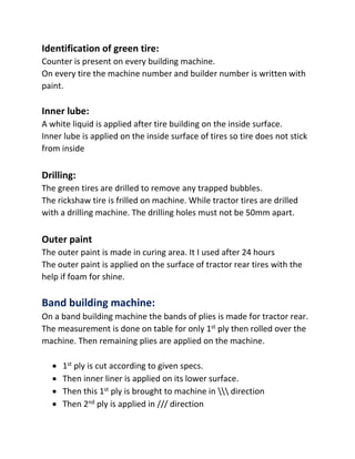
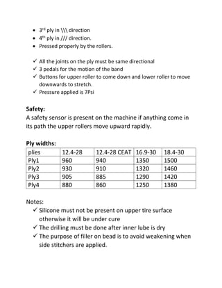
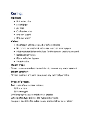
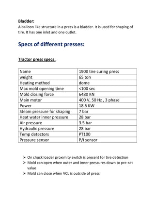
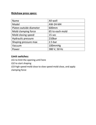
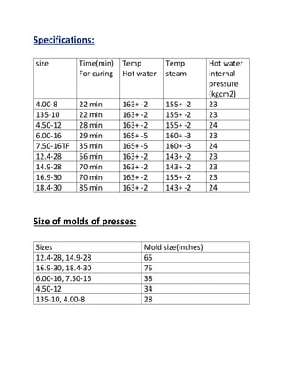
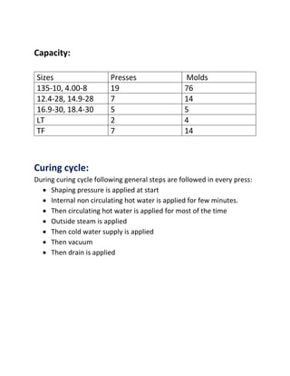
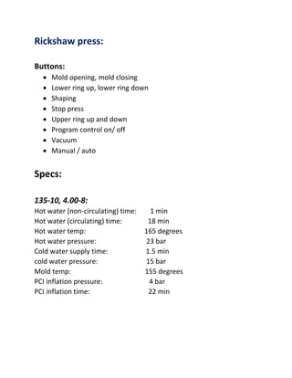
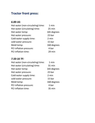
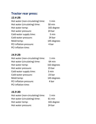
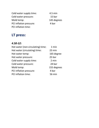
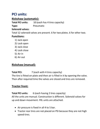
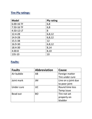
Technical tire department
Report submitted to:
Mr. Abdullah Aftab
Report submitted by:
Hassan Bilal (MTO)
Code: 01848
Department head:
Abdullah Aftab
Technical tire:
1) Agriculture tire
2) Rickshaw tire
Tire components:
1) Tread 2)Ply 3)Bead wire 4)Chaffer 5)Inner liner
Rickshaw tire Sizes:
 4.00-8
 135-10
Tractor tire sizes:
Front:
 6.00-16
 7.50-16
Rear:
 12.4-28
 14.9-28
 16.9-30
 18.4-30
 15.5-38
Light truck (LT):
 4.50-12
 6.50-14
 7.50-16
Duplex extruder:
Two extruders are present of different sizes:
1) 250 mm extruder
2) 200 mm extruder
Parts of extruder:
Feeding conveyer:
Two feeding conveyers are present for separate feeding to
extruders. Double layer of compound is fed to extruder. Rework
compound can also be fed. A proximity sensor is present on the end of
conveyer which detects the pulling force of extruder and set the speed
of conveyer according to it
Metal detector:
A metal detector is present on each conveyer. It detects any
foreign metal particle.
Emergency break:
A push break is present on start of conveyor to stop the
set up in case of emergency.
Temp. Control unit:
For each zone on duplex extruder pressure is maintained by TCU. It has
11 rod type heaters. 22 pipes for supplying and receiving water. The
condensers are present to cool down the hot water returning and then
heaters heat them to required set temp. RTDs and thermocouples are
present for temp detection.
A control unit is present to check if the water is coming or not in
heaters. If no water the set up will off. The pressure of water is 4.5 bar
A secondary water pipe is present if increase in pressure is required to
operate the heaters.
Zones temperature:
200 250
zones
screw 70 7o
Plastic 1 75 75
Plastic 2 75 80
extrusion 80 85
The dye attached at the end of extruder head has temp of 105 degree
centigrade.
Temp of extruder head:
Bottom mold zone 90
Middle mold zone 90
Top mold zone 90
Left cassette temp 115
Right cassette temp 115
Hydraulic pumps with sensor operation are used to operate the
extruder head.
The cassette at front has heaters to heat it for proper flow of
compound at corners.
Take off conveyer:
Take off conveyer speed is set according to specs to set the width and
thickness of compound.
Weighing scale:
A weighing scale of 950mm length measurement is present on
conveyer for weighing.
Dancing rolls:
Dancing rolls with proximity sensors are attached to transfer compound
on inclined conveyer without any stretch
Cooling conveyers:
The cooing is done with water. The tred is passed through three
conveyers for cooling.
Total length of conveyer:
Total length is 120 m
Cutting and collecting:
Cutting is done by the cutter operated by sensors.
Extruder speed:
Max: 24 rpm
But according to R and D specs maximum speed for rear sizes is 14 rpm.
size Ext 250 Ext 200 Conveyer speed
length/ sec
12.4-28 10.5 9.5 1.10
14.9-28 12 5.6 1.6
16.9-30 13 4 2.15
18.4-30 14 7 2.90
Tread parts:
1) Crown area
2) Shoulder area
3) Sidewall
Production / hour:
Size Num of treads
12.4-28 45
14.9-28 40
16.9-30 35
18.4-30 30
 All the sizes have single dies accept rickshaw which has double
die.
 In some sizes single extruder is also operational
 Sidewalls of big treads is made separately
Mini extruder (cushion compound):
Mini extruder is present for making cushioning compound. It
has also three rollers on which cushion compound is pasted on
underside of tread. Also the plastic sheet is applied under tread.
Cushion is not applied on 135-10 and tractor front tread
Color marking:
The color marking is not a standard but is done on changing of
formulation
Manual tire tread is marked with colour.
Pre-formers and dyes:
The pre-formers are inserted on opening the head. Every dye
has its own shape of pre-former to supply compound according to its
shape. The dye is fit in the cassette and the fingers grip it after. The
clamps are closed after the head is heated to preset temp.
Control panel:
1) Calendar arm current display
2) Calendar roll speed
3) Calendar speed control
4) Extruder arm current
5) Extruder roll speed
6) Top roll gap drive side
7) Top roll gap operator side
8) Bottom roll gap drive side
9) Bottom roll gap operator side
Tread cutter:
The length to be cut is entered on the panel on side off
cutter. Three sensors are present to run the conveyer of cutter.
Two lengths are entered set length and then the true length is
compared with this value before cutting.
Specifications of duplex extruder:
Extruder 250:
Screw speed: 2.6 to 26 rpm
Max power: 500 Kw
Max capacity 3500 kg/hour
Number of pins on barrel: 200
Extruder 200:
Screw speed: 2.8 to 28 rpm
Max power 500 Kw
Main motor 315 KW DC
Max capacity 2300 kg/ hour
Head:
Max width 800 mm
Max thickness 30mm
Hydraulic max pressure: 25MPa
Feeding conveyer:
Speed: 1.5 to 15m / min
Motor power: 1.5 KW
 15 min are required from feeding to mill to come out from
extruder at 14 rpm
 If the conveyer is run at 2 m/min it will require 5 min to travel
the whole conveyers to tread cutter.
Conveyer speeds:
size Line speed
4.00-8 6.20 +- 5 m/min
4.00-8 MRF 6.10+- 5 m/min
135-10 M 5.80+- 5 m/min
135-10 A 5.70+- 5 m/min
135-10 PP 5.80+- 5 m/min
4.50-12 4.50+- 5 m/min
6.00-16 3.50+- 10 m/min
7.50-16 2.80+- 10m/ min
12.4-28 2.10+- 10m/ min
14.9-28 1.90+- 10m/ min
16.9-30 1.60+- 10m/ min
18.4-30 1.10+- 10m/ min
Calendar overview:
Danier is the unit of thread.
 D1 is single thread code
 D2 is for double twisted thread
Weight for single thread 900m is written on specs.
The thread chosen is according to specs and ply rating.
Chaffer is made of 840 D1 x 840 D1 chord with F1260 compound on
it.
Ply roll:
On every roll following info is written:
 Chord name
 Compound name
 Date and shift name.
Ply cutter:
At start a rotating stand is present for ply roll. A standby roll is
present at the back.
The cloth roll is 300m long.
Control Buttons:
A switch button for operating it manual or automatic
One button moves the roll clockwise and one anti-clockwise.
A pneumatic break is present on rolls for stopping them.
The ply is supplied by passing through different rolls.
Banana rolls are present to spread the ply and to avoid any wrinkle.
The screw like rollers are present for pushing ply forward.
The ply roll is unrolled by up and down movement of rollers before
cutter.
At start between rollers a sensor is present for detection of presence of
ply.
On the cutting conveyer a roller is present for pressing the ply with
conveyer.
A servo motor is present to measure the revolutions and programmed
to calculate the length to be cut.
Max average waste is 40 to 50 kg per shift.
Angles for cutting ply:
Size Angle
4.00-8 60
135-10 63
4.00-8 (new auto) 65
12.4-28 57
14.9-28 59
16.9-30 60
18.4-30 62
6.00-16TF 60
7.50-16TF 60
4.50-12LT 57
6.50-14LT 60
7.50-16LT 60
 Cutter moving stand has four sensors to start stop motor.
 On cutter a pneumatic jack is present for moving motor up and
down.
 For adjusting the angle a handle is present to lift the cutter
assembly.
 The motor moves clockwise and anti-clockwise for cutter
movement. The dampers are present on the end of cutter path.
Control panel:
Motor forward backward
Emergency
Auto/manual
Conveyer on off
Ply width.
Bead wire machine:
size rounds wires
4.00-8 4 5
135-10 5 4
12.4-28 7 7
14.9-28 8 8
16.9-30 9 9
18.4-30 10 9
6.00-16TF 5 6
7.50-16TF 6 6
4.50-12LT 5 4
6.50-14LT 6 6
7.50-16LT 9 7
 6 wire rolls are present at start. According to requirement the
wires are taken. Leather brakes are used on rolls. When wire is
required it rolls by the pulling force.
 Before extruder three rolls are present on which heaters are
attached to heat the wire.
 B100 compound enters in extruder and coating is done on the
wire.
 Two cooling drums are for cooling and pull wire.
 Then a balancing mechanism is present to move up and down.
The rolls don’t stop but the balancing machine moves up and
down to receive the wire coming during bead cutting.
 6 pneumatic pumps are present on cutter.
 1 supply wire forward.
 2nd cuts the wire
 3rd, 4th are for joining wire
 5th, 6th are for compressing the wheel to remove the bead.
The same mechanism is on tractor bead wire machine. But the rolls
of wires are 10 at start.
Control panel:
 Stop lever
 Alternating clamp
 Guide wheel on/ off
 Wire feeding on/off
 Cutter return
 Push off break
Capacity:
4.00-8 size 19 rings can be formed in 1 min
6.00-16 size 5 rings in 1 min
Filler and flapper machine:
Filler is made by applying dye on the extruder of bead wire machine.
This filler is applied on the machines present at the back of bead wire
machine. The filler is applied on some beads of LT while filler with
flapper is applied on tractor rear bead wires.
Tire building machine:
400-8(manual) rickshaw tire:
1) Isth the drum Is compressed and the bead wires are set on sides
of drum
2) Inner liner is applied on the drum
3) 1st ply is applied in //// angle
4) 2nd ply is applied in angle
5) The plies are folded inward
6) 2 bead wires are applied and the plies are folded outward
7) 3rd ply is applied in //// angle
8) 4th ply is applied in  angle
9) The lower stitchers and hand stitchers are used.
10) Tread is applied at the and the joint is pressed strongly
4.00-8 automatic:
All the procedure is same just the bead fitting and the folding is
automatic by the fingers and bladder inflation and deflation.
3 lasers (LD-071 DC 6V 100mA) are present to check the level of plies.
3 pedals for the motion of drum in both directions and one pedal for
break.
The auto machine is operated by one button only.
The ply servicers are operated my motors. They are both automatic and
manual for motion of ply.
Capacity:
7 auto and 5 manual machines are present. The auto machines are
fixed to specific size but manual can operate on both sizes by changing
the drum
Wrinkles are removed by solvent oil.
135-10 tire building machine:
1) Inner liner is applied on drum
2) 2 plies in opposite angle like shown above(///,)
3) Turn them by applying bead wire in outside direction
4) Breaker is applied at the mid area
5) Chaffer is applied at the ends of plies
6) Hand stitcher is applied
7) Tread is applied and hand stitcher and down stitchers are applied
Four lasers are present on this machine.
The tread is fully coated with cement solution C900. The joint is coated
before and left for 2 hours.
Automatic machine tread is large in length and width is less
Manual tread is less is short in length and large in width
12.4-28 tire building machine:
1) Bead wire are adjusted on both sides of machine
2) Ply is brought from ply building machine
3) Fold inside the plies and apply bead
4) Now fold the plies outside by hand
5) Back stitcher and then the bottom stitcher are applied
6) Chaffer are applied on both sides of the tire
7) Now the tread is applied
8) Bottom and hand stitcher is applied while rolling
Pedals:
Break, forward slow, backward slow, forward fast, backward fast.
16.9-30 tire building:
1) Ply band is brought from the band building consisting of four plies
2) Fold inside all the plies end and apply bead wire with flapper
3) Apply chaffer on both sides
4) Apply side wall on both sides and use hand stitcher to bend it
uniformly
5) Apply the tread
6) Apply bottom stitcher at the end
6.00-16 TF tire building:
1) Inner liner
2) 1st ply 
3) 2nd ply ///
4) 3rd ply 
5) Apply beads and the fold ply outward
6) Apply braker
7) Apply chaffer at the ends
8) Back stitcher and hand stitcher are applied
9) At the end apply tread
4.50-12 LT:
1) Insert bead wire and expand the drum
2) Apply inner liner on drum
3) 1st ply 
4) Push button and pull the 2nd ply ///
5) 3rd ply 
6) Apply beads by fingers and fold the ply by the bladder
7) 4th ply //
8) Chaffer is applied
9) Side stitcher
10) Breaker 
11) Hand stitcher and down stitcher
12) Apply tread then hand stitcher
13) Down stitcher at the end for pressing
7.50-16 TF tire building:
1) Inner liner is applied at first
2) 1st ply in //// direction
3) 2nd ply in  direction
4) 3rd ply in //// direction
5) Fold inside apply bead with filler on it
6) And then fold outside
7) Breaker is applied
8) Apply chaffer
9) At the end tred is applied
10) Hand stitcher and down tread stitcher is applied.
Tire building rules:
1) Inner liner is applied on whole width of drum and overlapping
must be less than 3mm.
2) Use ply without wrinkles
3) Ply joints must not be greater than three thread
4) MC/ rick ply joint 3-4 thread
5) LT /agriculture front ply joint 5-6 thread
6) Agriculture rear ply joint 6-8 threads
7) Required air pressure 0.6 MPa
8) Ply sticher pressure car tire = 2kg/cm2
9) Tred stitcher pressure car tire= 3.5 kg/cm2
Joint press machine:
1) 4-5 kg pressure is required
2) Apply joint by keeping tire straight
3) Check if there is any air bubble
Pneumatic operation
Capacities of making green tire:
Tires made per shift (8 hours)
size Number of tires
per shift
Max time
4.00-8 auto 160 3.5 min
4.00-8 manual 90 4.5 min
135-10 auto 130 3.32 min
135-10 manual 80 7.22 min
6.00-16 40
750-16 35
12.4-28 25 10.3 min
14.9-28 20 11.2 min
16.9-30 16 12.3 min
18.4-30 10
Max tire made per hour on register record:
Size Num of tires/hour
135-10 auto 16
135-10 manual 10
4.00-8 10
4.50-12 5
6.00-16 auto 5
6.00-16 manual 5
7.50-16 4
12.4-28(ceat) 3
14.9-28 3
16.9-30 2
Green tire specification sheet:
Following info about tire is given on sheet:
 Fabric used
 Epi
 Compound used
 Cure angle
 Angle and width of plies
 Bias cutter
 Length, gauge and weight of plies
 Tread weight compound and dimensions of shoulder ,crown areas
and ends
 Bead circumference and diameter
 Tread profile
 Tire weight
Identification of green tire:
Counter is present on every building machine.
On every tire the machine number and builder number is written with
paint.
Inner lube:
A white liquid is applied after tire building on the inside surface.
Inner lube is applied on the inside surface of tires so tire does not stick
from inside
Drilling:
The green tires are drilled to remove any trapped bubbles.
The rickshaw tire is frilled on machine. While tractor tires are drilled
with a drilling machine. The drilling holes must not be 50mm apart.
Outer paint
The outer paint is made in curing area. It I used after 24 hours
The outer paint is applied on the surface of tractor rear tires with the
help if foam for shine.
Band building machine:
On a band building machine the bands of plies is made for tractor rear.
The measurement is done on table for only 1st ply then rolled over the
machine. Then remaining plies are applied on the machine.
 1st ply is cut according to given specs.
 Then inner liner is applied on its lower surface.
 Then this 1st ply is brought to machine in  direction
 Then 2nd ply is applied in /// direction
 3rd ply in  direction
 4th ply in /// direction.
 Pressed properly by the rollers.
 All the joints on the ply must be same directional
 3 pedals for the motion of the band
 Buttons for upper roller to come down and lower roller to move
downwards to stretch.
 Pressure applied is 7Psi
Safety:
A safety sensor is present on the machine if anything come in
its path the upper rollers move upward rapidly.
Ply widths:
plies 12.4-28 12.4-28 CEAT 16.9-30 18.4-30
Ply1 960 940 1350 1500
Ply2 930 910 1320 1460
Ply3 905 885 1290 1420
Ply4 880 860 1250 1380
Notes:
 Silicone must not be present on upper tire surface
otherwise it will be under cure
 The drilling must be done after inner lube is dry
 The purpose of filler on bead is to avoid weakening when
side stitchers are applied.
Curing:
Pipeline:
 Hot water pipe
 Steam pipe
 Air pipe
 Cool water pipe
 Drain of steam
 Drain of water
Valves:
 Diaphragm valves are used of different sizes
 No return valves(check valve) are used on steam pipes
 Pilot operated Solenoid valves for the control circuitry are used.
 Isolating ball valves
 Globe valve for bypass
 Shuttle valve
Steam traps:
Steam traps are used on steam inlets to remove any water content
Steam strainer:
Stream strainers are used to remove any external particles.
Types of presses:
Two types of presses are present:
1) Dome type
2) Platen type
Dome type presses are mechanical presses
While platen type presses are hydraulic presses.
In a press one inlet for outer steam, and outlet for outer steam
Bladder:
A balloon like structure in a press is a bladder. It is used for shaping of
tire. It has one inlet and one outlet.
Specs of different presses:
Tractor press specs:
Name 1900 tire curing press
weight 65 ton
Heating method dome
Max mold opening time <100 sec
Mold closing force 6480 KN
Main motor 400 V, 50 Hz , 3 phase
Power 18.5 KW
Steam pressure for shaping 7 bar
Heat water inner pressure 28 bar
Air pressure 3.5 bar
Hydraulic pressure 28 bar
Temp detectors PT100
Pressure sensor P/I sensor
 On chuck loader proximity switch is present for tire detection
 Mold can open when outer and inner pressures down to pre-set
value
 Mold can close when VCL is outside of press
Rickshaw press specs:
Name All-well
Model AW-24-M4
Platen outside diameter 600mm
Mold clamping force 65 to each mold
Mold closing speed 15 sec
Hydraulic pressure 210bar
Shaping pressure max 2.5 bar
Vacuum 100mmHg
Power 380 V, 50 Hz
Limit switches:
LS1 to limit the opening until here
LS2 to start shaping
LS3 high speed mold close to slow speed mold close, and apply
clamping force
Specifications:
size Time(min)
For curing
Temp
Hot water
Temp
steam
Hot water
internal
pressure
(kgcm2)
4.00-8 22 min 163+ -2 155+ -2 23
135-10 22 min 163+ -2 155+ -2 23
4.50-12 28 min 163+ -2 155+ -2 24
6.00-16 29 min 165+ -5 160+ -3 23
7.50-16TF 35 min 165+ -5 160+ -3 24
12.4-28 56 min 163+ -2 143+ -2 23
14.9-28 70 min 163+ -2 143+ -2 23
16.9-30 70 min 163+ -2 155+ -2 23
18.4-30 85 min 163+ -2 143+ -2 24
Size of molds of presses:
Sizes Mold size(inches)
12.4-28, 14.9-28 65
16.9-30, 18.4-30 75
6.00-16, 7.50-16 38
4.50-12 34
135-10, 4.00-8 28
Capacity:
Sizes Presses Molds
135-10, 4.00-8 19 76
12.4-28, 14.9-28 7 14
16.9-30, 18.4-30 5 5
LT 2 4
TF 7 14
Curing cycle:
During curing cycle following general steps are followed in every press:
 Shaping pressure is applied at start
 Internal non circulating hot water is applied for few minutes.
 Then circulating hot water is applied for most of the time
 Outside steam is applied
 Then cold water supply is applied
 Then vacuum
 Then drain is applied
Rickshaw press:
Buttons:
 Mold opening, mold closing
 Lower ring up, lower ring down
 Shaping
 Stop press
 Upper ring up and down
 Program control on/ off
 Vacuum
 Manual / auto
Specs:
135-10, 4.00-8:
Hot water (non-circulating) time: 1 min
Hot water (circulating) time: 18 min
Hot water temp: 165 degrees
Hot water pressure: 23 bar
Cold water supply time: 1.5 min
cold water pressure: 15 bar
Mold temp: 155 degrees
PCI inflation pressure: 4 bar
PCI inflation time: 22 min
Tractor front press:
6.00-16:
Hot water (non-circulating) time: 1 min
Hot water (circulating) time: 25 min
Hot water temp: 165 degrees
Hot water pressure: 23 bar
Cold water supply time: 2 min
cold water pressure: 15 bar
Mold temp: 160 degrees
PCI inflation pressure: 4 bar
PCI inflation time: 29 min
7.50-16 TF:
Hot water (non-circulating) time: 1 min
Hot water (circulating) time: 31 min
Hot water temp: 165 degrees
Hot water pressure: 23 bar
Cold water supply time: 2 min
cold water pressure: 15 bar
Mold temp: 160 degrees
PCI inflation pressure: 4 bar
PCI inflation time: 35 min
Tractor rear press:
12.4-28:
Hot water (non-circulating) time: 1 min
Hot water (circulating) time: 50 min
Hot water temp: 165 degree
Hot water pressure: 24 bar
Cold water supply time: 3 min
Cold water pressure: 24 bar
Mold temp: 145 degrees
PCI inflation pressure: 4 bar
PCI inflation time:
14.9-28:
Hot water (non-circulating) time: 1 min
Hot water (circulating) time: 64 min
Hot water temp: 163 degrees
Hot water pressure: 23 bar
Cold water supply time: 3 min
Cold water pressure: 23 bar
Mold temp: 145 degrees
PCI inflation pressure: 4 bar
PCI inflation time:
16.9-30:
Hot water (non-circulating) time: 1 min
Hot water (circulating) time: 61 min
Hot water temp: 165 degree
Hot water pressure: 24 bar
Cold water supply time: 4.5 min
Cold water pressure: 15 bar
Mold temp: 145 degrees
PCI inflation pressure: 4 bar
PCI inflation time:
LT press:
4.50-12:
Hot water (non-circulating) time: 1 min
Hot water (circulating) time: 23 min
Hot water temp: 165 degree
Hot water pressure: 25 bar
Cold water supply time: 2 min
Cold water pressure: 24 bar
Mold temp: 155 degrees
PCI inflation pressure: 4 bar
PCI inflation time: 56 min
PCI units:
Rickshaw (automatic):
Total PCI units: 10 (each has 4 tires capacity)
Type: Pneumatic
Solenoid valves:
Total 12 solenoid valves are present. 6 for two plates. 6 for other two.
Functions:
1) Jack open
2) Lock open
3) Jack close
4) Lock close
5) Air in
6) Air out
Rickshaw (manual):
Total PCI: 7 (each with 4 tires capacity)
The tire is fitted on plate and then air is filled in it by opening the valve.
Then after required time the valves are closed and tires are removed.
Tractor front:
Total PCI units: 6 (each having 2 tires capacity)
All the units are manual. Construction is different. Solenoid valves for
up and down movement. FRL units are attached.
 Air pressure is fixed in all 4 to 5 bar.
 Tractor rear tires are not placed on PSI because they are not high
speed tires.
Tire Ply ratings:
Model Ply rating
6.00-16 TF 6,8
7.50-16 TF 6,8
4.50-12 LT 8
12.4-28 6,8,12
14.9-28 6,8,12
15.5-38 12
16.9-30 6,8,12
18.4-30 8,14
4.00-8 8,10
135-10 10
Faults:
Faults Abbreviation Cause
Air bubble AB Foreign matter
Tire under cure
Joint mark JM Line on a joint due
to poor joint
Under cure UC Round time less
Temp issue
Bead out BO Tire not set
properly on
bladder
Bead not fixed
properly
Ply fault PF Inner lube not
applied properly
Mechanical fault MF Any mechanical
problem
Electrical fault EF Any electrical
problem
Bead crush BC Tire not set
properly
Foreign matter FM Any particle left on
tire
Thin bead TB Bladder weak
Thin side TS Plies not applied
properly and folded
Jalli JAL Water inside due to
bladder leak
Press man fault PMF Press man not
fitted tire properly
Buckle(bunny) BN
Ring leak RL Bladder ring leak
Same angle SA Plies applied at
same angle
Bead marking BM Tread away from
bead flow not
proper
Improvements required:
1) Ply cutting is not proper. There is variation in width of every ply
2) Metal detector on duplex extruder must operate to avoid foreign
metals
3) The drums of building machines are a bit loose.
4) The joints of ply must be applied at specific points to balance
5) The plies must be of specific length. No joints must be applied
6) Lasers must also be present on band building machines for level
check of plies
7) The solutions used on tire must be replaced freshly with the start
of new shift
8) The leakage on presses must be controlled
9) The inner liner must not be stretched on drum
10) The builder must not touch the plies frequently, solvent oil
must be used in less quantity
11) The press opening alarms must be set on every press
12) The liner must be folded properly and should be placed on
stands not on floor

technical tyre

  • 1.
    Technical tire department Reportsubmitted to: Mr. Abdullah Aftab Report submitted by: Hassan Bilal (MTO) Code: 01848
  • 2.
    Department head: Abdullah Aftab Technicaltire: 1) Agriculture tire 2) Rickshaw tire Tire components: 1) Tread 2)Ply 3)Bead wire 4)Chaffer 5)Inner liner Rickshaw tire Sizes:  4.00-8  135-10 Tractor tire sizes: Front:  6.00-16  7.50-16 Rear:  12.4-28  14.9-28  16.9-30  18.4-30  15.5-38 Light truck (LT):  4.50-12  6.50-14  7.50-16
  • 3.
    Duplex extruder: Two extrudersare present of different sizes: 1) 250 mm extruder 2) 200 mm extruder Parts of extruder: Feeding conveyer: Two feeding conveyers are present for separate feeding to extruders. Double layer of compound is fed to extruder. Rework compound can also be fed. A proximity sensor is present on the end of conveyer which detects the pulling force of extruder and set the speed of conveyer according to it Metal detector: A metal detector is present on each conveyer. It detects any foreign metal particle. Emergency break: A push break is present on start of conveyor to stop the set up in case of emergency. Temp. Control unit: For each zone on duplex extruder pressure is maintained by TCU. It has 11 rod type heaters. 22 pipes for supplying and receiving water. The condensers are present to cool down the hot water returning and then heaters heat them to required set temp. RTDs and thermocouples are present for temp detection.
  • 4.
    A control unitis present to check if the water is coming or not in heaters. If no water the set up will off. The pressure of water is 4.5 bar A secondary water pipe is present if increase in pressure is required to operate the heaters. Zones temperature: 200 250 zones screw 70 7o Plastic 1 75 75 Plastic 2 75 80 extrusion 80 85 The dye attached at the end of extruder head has temp of 105 degree centigrade. Temp of extruder head: Bottom mold zone 90 Middle mold zone 90 Top mold zone 90 Left cassette temp 115 Right cassette temp 115 Hydraulic pumps with sensor operation are used to operate the extruder head. The cassette at front has heaters to heat it for proper flow of compound at corners.
  • 5.
    Take off conveyer: Takeoff conveyer speed is set according to specs to set the width and thickness of compound. Weighing scale: A weighing scale of 950mm length measurement is present on conveyer for weighing. Dancing rolls: Dancing rolls with proximity sensors are attached to transfer compound on inclined conveyer without any stretch Cooling conveyers: The cooing is done with water. The tred is passed through three conveyers for cooling. Total length of conveyer: Total length is 120 m Cutting and collecting: Cutting is done by the cutter operated by sensors.
  • 6.
    Extruder speed: Max: 24rpm But according to R and D specs maximum speed for rear sizes is 14 rpm. size Ext 250 Ext 200 Conveyer speed length/ sec 12.4-28 10.5 9.5 1.10 14.9-28 12 5.6 1.6 16.9-30 13 4 2.15 18.4-30 14 7 2.90 Tread parts: 1) Crown area 2) Shoulder area 3) Sidewall Production / hour: Size Num of treads 12.4-28 45 14.9-28 40 16.9-30 35 18.4-30 30  All the sizes have single dies accept rickshaw which has double die.  In some sizes single extruder is also operational  Sidewalls of big treads is made separately
  • 7.
    Mini extruder (cushioncompound): Mini extruder is present for making cushioning compound. It has also three rollers on which cushion compound is pasted on underside of tread. Also the plastic sheet is applied under tread. Cushion is not applied on 135-10 and tractor front tread Color marking: The color marking is not a standard but is done on changing of formulation Manual tire tread is marked with colour. Pre-formers and dyes: The pre-formers are inserted on opening the head. Every dye has its own shape of pre-former to supply compound according to its shape. The dye is fit in the cassette and the fingers grip it after. The clamps are closed after the head is heated to preset temp. Control panel: 1) Calendar arm current display 2) Calendar roll speed 3) Calendar speed control 4) Extruder arm current 5) Extruder roll speed 6) Top roll gap drive side 7) Top roll gap operator side 8) Bottom roll gap drive side 9) Bottom roll gap operator side
  • 8.
    Tread cutter: The lengthto be cut is entered on the panel on side off cutter. Three sensors are present to run the conveyer of cutter. Two lengths are entered set length and then the true length is compared with this value before cutting. Specifications of duplex extruder: Extruder 250: Screw speed: 2.6 to 26 rpm Max power: 500 Kw Max capacity 3500 kg/hour Number of pins on barrel: 200 Extruder 200: Screw speed: 2.8 to 28 rpm Max power 500 Kw Main motor 315 KW DC Max capacity 2300 kg/ hour Head: Max width 800 mm Max thickness 30mm Hydraulic max pressure: 25MPa Feeding conveyer: Speed: 1.5 to 15m / min Motor power: 1.5 KW
  • 9.
     15 minare required from feeding to mill to come out from extruder at 14 rpm  If the conveyer is run at 2 m/min it will require 5 min to travel the whole conveyers to tread cutter. Conveyer speeds: size Line speed 4.00-8 6.20 +- 5 m/min 4.00-8 MRF 6.10+- 5 m/min 135-10 M 5.80+- 5 m/min 135-10 A 5.70+- 5 m/min 135-10 PP 5.80+- 5 m/min 4.50-12 4.50+- 5 m/min 6.00-16 3.50+- 10 m/min 7.50-16 2.80+- 10m/ min 12.4-28 2.10+- 10m/ min 14.9-28 1.90+- 10m/ min 16.9-30 1.60+- 10m/ min 18.4-30 1.10+- 10m/ min Calendar overview: Danier is the unit of thread.  D1 is single thread code  D2 is for double twisted thread Weight for single thread 900m is written on specs. The thread chosen is according to specs and ply rating. Chaffer is made of 840 D1 x 840 D1 chord with F1260 compound on it.
  • 10.
    Ply roll: On everyroll following info is written:  Chord name  Compound name  Date and shift name. Ply cutter: At start a rotating stand is present for ply roll. A standby roll is present at the back. The cloth roll is 300m long. Control Buttons: A switch button for operating it manual or automatic One button moves the roll clockwise and one anti-clockwise. A pneumatic break is present on rolls for stopping them. The ply is supplied by passing through different rolls. Banana rolls are present to spread the ply and to avoid any wrinkle. The screw like rollers are present for pushing ply forward. The ply roll is unrolled by up and down movement of rollers before cutter. At start between rollers a sensor is present for detection of presence of ply. On the cutting conveyer a roller is present for pressing the ply with conveyer. A servo motor is present to measure the revolutions and programmed to calculate the length to be cut. Max average waste is 40 to 50 kg per shift.
  • 11.
    Angles for cuttingply: Size Angle 4.00-8 60 135-10 63 4.00-8 (new auto) 65 12.4-28 57 14.9-28 59 16.9-30 60 18.4-30 62 6.00-16TF 60 7.50-16TF 60 4.50-12LT 57 6.50-14LT 60 7.50-16LT 60  Cutter moving stand has four sensors to start stop motor.  On cutter a pneumatic jack is present for moving motor up and down.  For adjusting the angle a handle is present to lift the cutter assembly.  The motor moves clockwise and anti-clockwise for cutter movement. The dampers are present on the end of cutter path. Control panel: Motor forward backward Emergency Auto/manual Conveyer on off Ply width.
  • 12.
    Bead wire machine: sizerounds wires 4.00-8 4 5 135-10 5 4 12.4-28 7 7 14.9-28 8 8 16.9-30 9 9 18.4-30 10 9 6.00-16TF 5 6 7.50-16TF 6 6 4.50-12LT 5 4 6.50-14LT 6 6 7.50-16LT 9 7  6 wire rolls are present at start. According to requirement the wires are taken. Leather brakes are used on rolls. When wire is required it rolls by the pulling force.  Before extruder three rolls are present on which heaters are attached to heat the wire.  B100 compound enters in extruder and coating is done on the wire.  Two cooling drums are for cooling and pull wire.  Then a balancing mechanism is present to move up and down. The rolls don’t stop but the balancing machine moves up and down to receive the wire coming during bead cutting.  6 pneumatic pumps are present on cutter.  1 supply wire forward.
  • 13.
     2nd cutsthe wire  3rd, 4th are for joining wire  5th, 6th are for compressing the wheel to remove the bead. The same mechanism is on tractor bead wire machine. But the rolls of wires are 10 at start. Control panel:  Stop lever  Alternating clamp  Guide wheel on/ off  Wire feeding on/off  Cutter return  Push off break Capacity: 4.00-8 size 19 rings can be formed in 1 min 6.00-16 size 5 rings in 1 min Filler and flapper machine: Filler is made by applying dye on the extruder of bead wire machine. This filler is applied on the machines present at the back of bead wire machine. The filler is applied on some beads of LT while filler with flapper is applied on tractor rear bead wires.
  • 14.
    Tire building machine: 400-8(manual)rickshaw tire: 1) Isth the drum Is compressed and the bead wires are set on sides of drum 2) Inner liner is applied on the drum 3) 1st ply is applied in //// angle 4) 2nd ply is applied in angle 5) The plies are folded inward 6) 2 bead wires are applied and the plies are folded outward 7) 3rd ply is applied in //// angle 8) 4th ply is applied in angle 9) The lower stitchers and hand stitchers are used. 10) Tread is applied at the and the joint is pressed strongly 4.00-8 automatic: All the procedure is same just the bead fitting and the folding is automatic by the fingers and bladder inflation and deflation. 3 lasers (LD-071 DC 6V 100mA) are present to check the level of plies. 3 pedals for the motion of drum in both directions and one pedal for break. The auto machine is operated by one button only. The ply servicers are operated my motors. They are both automatic and manual for motion of ply. Capacity: 7 auto and 5 manual machines are present. The auto machines are fixed to specific size but manual can operate on both sizes by changing the drum Wrinkles are removed by solvent oil.
  • 15.
    135-10 tire buildingmachine: 1) Inner liner is applied on drum 2) 2 plies in opposite angle like shown above(///,) 3) Turn them by applying bead wire in outside direction 4) Breaker is applied at the mid area 5) Chaffer is applied at the ends of plies 6) Hand stitcher is applied 7) Tread is applied and hand stitcher and down stitchers are applied Four lasers are present on this machine. The tread is fully coated with cement solution C900. The joint is coated before and left for 2 hours. Automatic machine tread is large in length and width is less Manual tread is less is short in length and large in width 12.4-28 tire building machine: 1) Bead wire are adjusted on both sides of machine 2) Ply is brought from ply building machine 3) Fold inside the plies and apply bead 4) Now fold the plies outside by hand 5) Back stitcher and then the bottom stitcher are applied 6) Chaffer are applied on both sides of the tire 7) Now the tread is applied 8) Bottom and hand stitcher is applied while rolling Pedals: Break, forward slow, backward slow, forward fast, backward fast.
  • 16.
    16.9-30 tire building: 1)Ply band is brought from the band building consisting of four plies 2) Fold inside all the plies end and apply bead wire with flapper 3) Apply chaffer on both sides 4) Apply side wall on both sides and use hand stitcher to bend it uniformly 5) Apply the tread 6) Apply bottom stitcher at the end 6.00-16 TF tire building: 1) Inner liner 2) 1st ply 3) 2nd ply /// 4) 3rd ply 5) Apply beads and the fold ply outward 6) Apply braker 7) Apply chaffer at the ends 8) Back stitcher and hand stitcher are applied 9) At the end apply tread 4.50-12 LT: 1) Insert bead wire and expand the drum 2) Apply inner liner on drum 3) 1st ply 4) Push button and pull the 2nd ply /// 5) 3rd ply 6) Apply beads by fingers and fold the ply by the bladder 7) 4th ply // 8) Chaffer is applied 9) Side stitcher
  • 17.
    10) Breaker 11)Hand stitcher and down stitcher 12) Apply tread then hand stitcher 13) Down stitcher at the end for pressing 7.50-16 TF tire building: 1) Inner liner is applied at first 2) 1st ply in //// direction 3) 2nd ply in direction 4) 3rd ply in //// direction 5) Fold inside apply bead with filler on it 6) And then fold outside 7) Breaker is applied 8) Apply chaffer 9) At the end tred is applied 10) Hand stitcher and down tread stitcher is applied. Tire building rules: 1) Inner liner is applied on whole width of drum and overlapping must be less than 3mm. 2) Use ply without wrinkles 3) Ply joints must not be greater than three thread 4) MC/ rick ply joint 3-4 thread 5) LT /agriculture front ply joint 5-6 thread 6) Agriculture rear ply joint 6-8 threads 7) Required air pressure 0.6 MPa 8) Ply sticher pressure car tire = 2kg/cm2 9) Tred stitcher pressure car tire= 3.5 kg/cm2
  • 18.
    Joint press machine: 1)4-5 kg pressure is required 2) Apply joint by keeping tire straight 3) Check if there is any air bubble Pneumatic operation Capacities of making green tire: Tires made per shift (8 hours) size Number of tires per shift Max time 4.00-8 auto 160 3.5 min 4.00-8 manual 90 4.5 min 135-10 auto 130 3.32 min 135-10 manual 80 7.22 min 6.00-16 40 750-16 35 12.4-28 25 10.3 min 14.9-28 20 11.2 min 16.9-30 16 12.3 min 18.4-30 10
  • 19.
    Max tire madeper hour on register record: Size Num of tires/hour 135-10 auto 16 135-10 manual 10 4.00-8 10 4.50-12 5 6.00-16 auto 5 6.00-16 manual 5 7.50-16 4 12.4-28(ceat) 3 14.9-28 3 16.9-30 2 Green tire specification sheet: Following info about tire is given on sheet:  Fabric used  Epi  Compound used  Cure angle  Angle and width of plies  Bias cutter  Length, gauge and weight of plies  Tread weight compound and dimensions of shoulder ,crown areas and ends  Bead circumference and diameter  Tread profile  Tire weight
  • 20.
    Identification of greentire: Counter is present on every building machine. On every tire the machine number and builder number is written with paint. Inner lube: A white liquid is applied after tire building on the inside surface. Inner lube is applied on the inside surface of tires so tire does not stick from inside Drilling: The green tires are drilled to remove any trapped bubbles. The rickshaw tire is frilled on machine. While tractor tires are drilled with a drilling machine. The drilling holes must not be 50mm apart. Outer paint The outer paint is made in curing area. It I used after 24 hours The outer paint is applied on the surface of tractor rear tires with the help if foam for shine. Band building machine: On a band building machine the bands of plies is made for tractor rear. The measurement is done on table for only 1st ply then rolled over the machine. Then remaining plies are applied on the machine.  1st ply is cut according to given specs.  Then inner liner is applied on its lower surface.  Then this 1st ply is brought to machine in direction  Then 2nd ply is applied in /// direction
  • 21.
     3rd plyin direction  4th ply in /// direction.  Pressed properly by the rollers.  All the joints on the ply must be same directional  3 pedals for the motion of the band  Buttons for upper roller to come down and lower roller to move downwards to stretch.  Pressure applied is 7Psi Safety: A safety sensor is present on the machine if anything come in its path the upper rollers move upward rapidly. Ply widths: plies 12.4-28 12.4-28 CEAT 16.9-30 18.4-30 Ply1 960 940 1350 1500 Ply2 930 910 1320 1460 Ply3 905 885 1290 1420 Ply4 880 860 1250 1380 Notes:  Silicone must not be present on upper tire surface otherwise it will be under cure  The drilling must be done after inner lube is dry  The purpose of filler on bead is to avoid weakening when side stitchers are applied.
  • 22.
    Curing: Pipeline:  Hot waterpipe  Steam pipe  Air pipe  Cool water pipe  Drain of steam  Drain of water Valves:  Diaphragm valves are used of different sizes  No return valves(check valve) are used on steam pipes  Pilot operated Solenoid valves for the control circuitry are used.  Isolating ball valves  Globe valve for bypass  Shuttle valve Steam traps: Steam traps are used on steam inlets to remove any water content Steam strainer: Stream strainers are used to remove any external particles. Types of presses: Two types of presses are present: 1) Dome type 2) Platen type Dome type presses are mechanical presses While platen type presses are hydraulic presses. In a press one inlet for outer steam, and outlet for outer steam
  • 23.
    Bladder: A balloon likestructure in a press is a bladder. It is used for shaping of tire. It has one inlet and one outlet. Specs of different presses: Tractor press specs: Name 1900 tire curing press weight 65 ton Heating method dome Max mold opening time <100 sec Mold closing force 6480 KN Main motor 400 V, 50 Hz , 3 phase Power 18.5 KW Steam pressure for shaping 7 bar Heat water inner pressure 28 bar Air pressure 3.5 bar Hydraulic pressure 28 bar Temp detectors PT100 Pressure sensor P/I sensor  On chuck loader proximity switch is present for tire detection  Mold can open when outer and inner pressures down to pre-set value  Mold can close when VCL is outside of press
  • 24.
    Rickshaw press specs: NameAll-well Model AW-24-M4 Platen outside diameter 600mm Mold clamping force 65 to each mold Mold closing speed 15 sec Hydraulic pressure 210bar Shaping pressure max 2.5 bar Vacuum 100mmHg Power 380 V, 50 Hz Limit switches: LS1 to limit the opening until here LS2 to start shaping LS3 high speed mold close to slow speed mold close, and apply clamping force
  • 25.
    Specifications: size Time(min) For curing Temp Hotwater Temp steam Hot water internal pressure (kgcm2) 4.00-8 22 min 163+ -2 155+ -2 23 135-10 22 min 163+ -2 155+ -2 23 4.50-12 28 min 163+ -2 155+ -2 24 6.00-16 29 min 165+ -5 160+ -3 23 7.50-16TF 35 min 165+ -5 160+ -3 24 12.4-28 56 min 163+ -2 143+ -2 23 14.9-28 70 min 163+ -2 143+ -2 23 16.9-30 70 min 163+ -2 155+ -2 23 18.4-30 85 min 163+ -2 143+ -2 24 Size of molds of presses: Sizes Mold size(inches) 12.4-28, 14.9-28 65 16.9-30, 18.4-30 75 6.00-16, 7.50-16 38 4.50-12 34 135-10, 4.00-8 28
  • 26.
    Capacity: Sizes Presses Molds 135-10,4.00-8 19 76 12.4-28, 14.9-28 7 14 16.9-30, 18.4-30 5 5 LT 2 4 TF 7 14 Curing cycle: During curing cycle following general steps are followed in every press:  Shaping pressure is applied at start  Internal non circulating hot water is applied for few minutes.  Then circulating hot water is applied for most of the time  Outside steam is applied  Then cold water supply is applied  Then vacuum  Then drain is applied
  • 27.
    Rickshaw press: Buttons:  Moldopening, mold closing  Lower ring up, lower ring down  Shaping  Stop press  Upper ring up and down  Program control on/ off  Vacuum  Manual / auto Specs: 135-10, 4.00-8: Hot water (non-circulating) time: 1 min Hot water (circulating) time: 18 min Hot water temp: 165 degrees Hot water pressure: 23 bar Cold water supply time: 1.5 min cold water pressure: 15 bar Mold temp: 155 degrees PCI inflation pressure: 4 bar PCI inflation time: 22 min
  • 28.
    Tractor front press: 6.00-16: Hotwater (non-circulating) time: 1 min Hot water (circulating) time: 25 min Hot water temp: 165 degrees Hot water pressure: 23 bar Cold water supply time: 2 min cold water pressure: 15 bar Mold temp: 160 degrees PCI inflation pressure: 4 bar PCI inflation time: 29 min 7.50-16 TF: Hot water (non-circulating) time: 1 min Hot water (circulating) time: 31 min Hot water temp: 165 degrees Hot water pressure: 23 bar Cold water supply time: 2 min cold water pressure: 15 bar Mold temp: 160 degrees PCI inflation pressure: 4 bar PCI inflation time: 35 min
  • 29.
    Tractor rear press: 12.4-28: Hotwater (non-circulating) time: 1 min Hot water (circulating) time: 50 min Hot water temp: 165 degree Hot water pressure: 24 bar Cold water supply time: 3 min Cold water pressure: 24 bar Mold temp: 145 degrees PCI inflation pressure: 4 bar PCI inflation time: 14.9-28: Hot water (non-circulating) time: 1 min Hot water (circulating) time: 64 min Hot water temp: 163 degrees Hot water pressure: 23 bar Cold water supply time: 3 min Cold water pressure: 23 bar Mold temp: 145 degrees PCI inflation pressure: 4 bar PCI inflation time: 16.9-30: Hot water (non-circulating) time: 1 min Hot water (circulating) time: 61 min Hot water temp: 165 degree Hot water pressure: 24 bar
  • 30.
    Cold water supplytime: 4.5 min Cold water pressure: 15 bar Mold temp: 145 degrees PCI inflation pressure: 4 bar PCI inflation time: LT press: 4.50-12: Hot water (non-circulating) time: 1 min Hot water (circulating) time: 23 min Hot water temp: 165 degree Hot water pressure: 25 bar Cold water supply time: 2 min Cold water pressure: 24 bar Mold temp: 155 degrees PCI inflation pressure: 4 bar PCI inflation time: 56 min
  • 31.
    PCI units: Rickshaw (automatic): TotalPCI units: 10 (each has 4 tires capacity) Type: Pneumatic Solenoid valves: Total 12 solenoid valves are present. 6 for two plates. 6 for other two. Functions: 1) Jack open 2) Lock open 3) Jack close 4) Lock close 5) Air in 6) Air out Rickshaw (manual): Total PCI: 7 (each with 4 tires capacity) The tire is fitted on plate and then air is filled in it by opening the valve. Then after required time the valves are closed and tires are removed. Tractor front: Total PCI units: 6 (each having 2 tires capacity) All the units are manual. Construction is different. Solenoid valves for up and down movement. FRL units are attached.  Air pressure is fixed in all 4 to 5 bar.  Tractor rear tires are not placed on PSI because they are not high speed tires.
  • 32.
    Tire Ply ratings: ModelPly rating 6.00-16 TF 6,8 7.50-16 TF 6,8 4.50-12 LT 8 12.4-28 6,8,12 14.9-28 6,8,12 15.5-38 12 16.9-30 6,8,12 18.4-30 8,14 4.00-8 8,10 135-10 10 Faults: Faults Abbreviation Cause Air bubble AB Foreign matter Tire under cure Joint mark JM Line on a joint due to poor joint Under cure UC Round time less Temp issue Bead out BO Tire not set properly on bladder
  • 33.
    Bead not fixed properly Plyfault PF Inner lube not applied properly Mechanical fault MF Any mechanical problem Electrical fault EF Any electrical problem Bead crush BC Tire not set properly Foreign matter FM Any particle left on tire Thin bead TB Bladder weak Thin side TS Plies not applied properly and folded Jalli JAL Water inside due to bladder leak Press man fault PMF Press man not fitted tire properly Buckle(bunny) BN Ring leak RL Bladder ring leak Same angle SA Plies applied at same angle Bead marking BM Tread away from bead flow not proper
  • 34.
    Improvements required: 1) Plycutting is not proper. There is variation in width of every ply 2) Metal detector on duplex extruder must operate to avoid foreign metals 3) The drums of building machines are a bit loose. 4) The joints of ply must be applied at specific points to balance 5) The plies must be of specific length. No joints must be applied 6) Lasers must also be present on band building machines for level check of plies 7) The solutions used on tire must be replaced freshly with the start of new shift 8) The leakage on presses must be controlled 9) The inner liner must not be stretched on drum 10) The builder must not touch the plies frequently, solvent oil must be used in less quantity 11) The press opening alarms must be set on every press 12) The liner must be folded properly and should be placed on stands not on floor