Download as PDF, PPTX
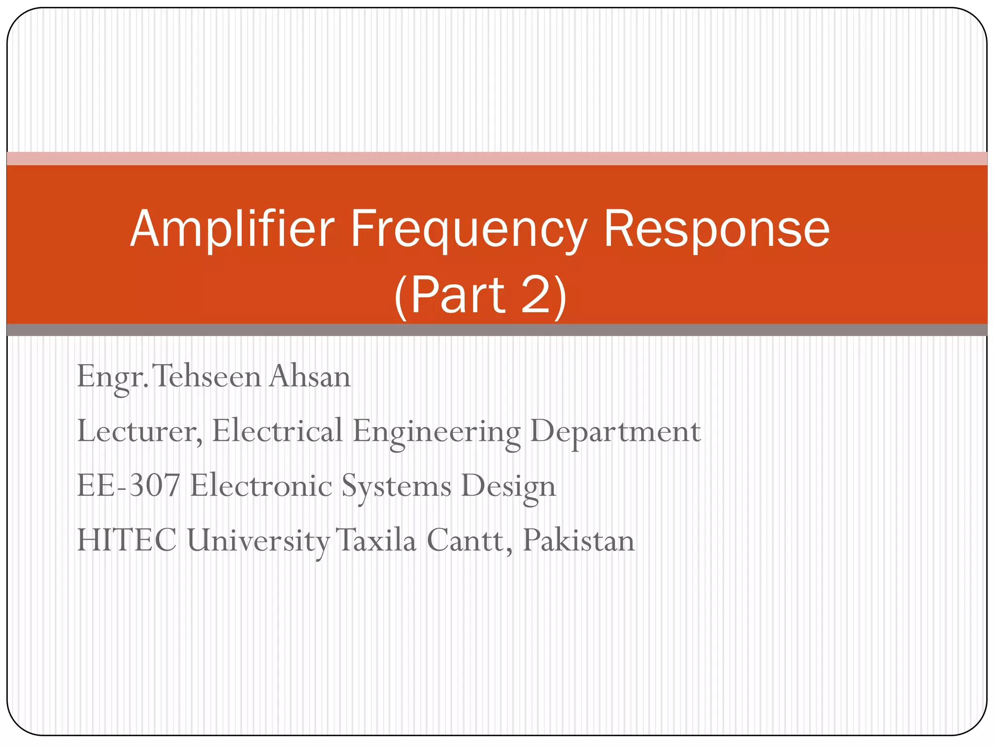
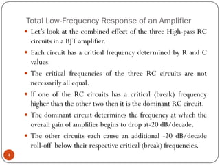
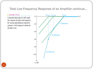
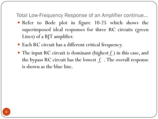
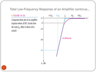
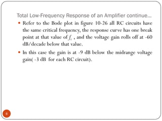
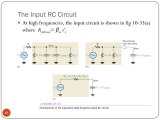
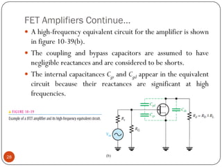
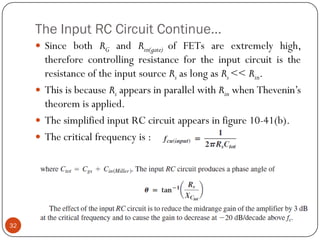
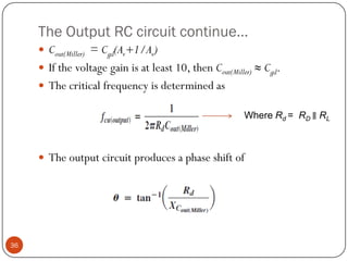
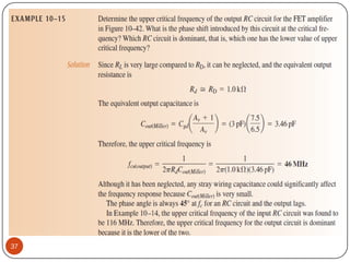
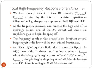
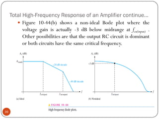
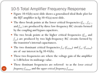
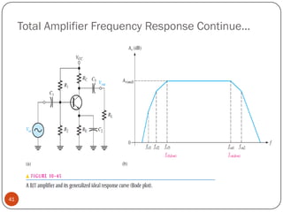
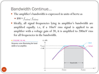
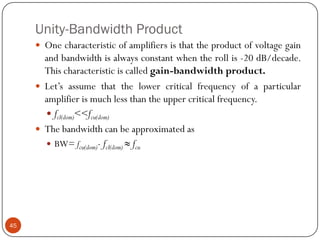
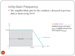
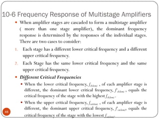
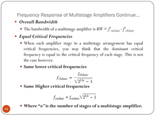
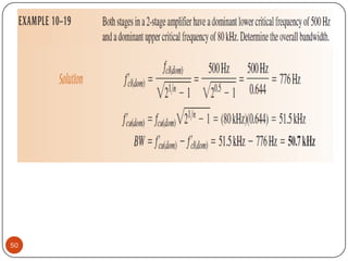

This document discusses the frequency response of amplifiers. It explains that an amplifier's frequency response can be analyzed using a Bode plot. An amplifier's bandwidth is defined as the range of frequencies between its lower and upper critical frequencies (fcl(dom) and fcu(dom)), where the voltage gain is 3dB below the midrange value. The unity-bandwidth product states that for an amplifier with a -20dB/decade roll-off, the product of its voltage gain and bandwidth remains constant. The unity-gain frequency, fT, is the frequency at which the amplifier's gain reaches 1, and it is always equal to the midrange voltage gain multiplied by the bandwidth. When analyzing multistage ampl


![RF Circuit Design - [Ch4-2] LNA, PA, and Broadband Amplifier](https://cdn.slidesharecdn.com/ss_thumbnails/ch4-2-150613064410-lva1-app6891-thumbnail.jpg?width=640&height=640&fit=bounds)


![RF Module Design - [Chapter 5] Low Noise Amplifier](https://cdn.slidesharecdn.com/ss_thumbnails/rfch5-150613070346-lva1-app6891-thumbnail.jpg?width=640&height=640&fit=bounds)


![RF Module Design - [Chapter 6] Power Amplifier](https://cdn.slidesharecdn.com/ss_thumbnails/rfch6-150613070347-lva1-app6891-thumbnail.jpg?width=640&height=640&fit=bounds)


