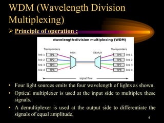
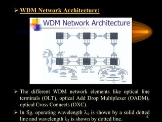
This document provides an overview of advances in optical fiber communication systems, including WDM, DWDM, SONET, and OTNs. It describes the basic principles and components of each technology. WDM and DWDM increase bandwidth by transmitting multiple wavelengths of light simultaneously over the same fiber. SONET provides a standard for fiber transmission and synchronization. OTNs were designed to transport IP and Ethernet traffic over optical networks.
An optical fiber is composed of a very thin glass rod which is divided into two concentric regions, called the core and cladding. A single finer can then be coated with a protective plastic called a buffer and strength materials, such as Kevlar and polymers Optical fibers are based entirely on the principle of total internal reflection.
In an optical communications system, information from the source is encoded into electrical signals that can drive the transmitter. The transmitter consists of an LED or laser and is pulsed at the incoming frequency. The transmitter performs an EO conversion.
Attenuation is
the reduction of signal strength or light power over the length of
the light-carrying medium. As the light signal travels down the fiber,
it losses power or attenuates.
Optical fiber is the technology associated with data transmission using light pulses travelling along with a long fiber which is usually made of plastic or glass. Metal wires are preferred for transmission in optical fiber communication as signals travel with fewer damages. Optical fibers are also unaffected by electromagnetic interference. The fiber optical cable uses the application of total internal reflection of light. The fibers are designed such that they facilitate the propagation of light along with the optical fiber depending on the requirement of power and distance of transmission. Single-mode fiber is used for long-distance transmission, while multimode fiber is used for shorter distances. The outer cladding of these fibers needs better protection than metal wires.
DWDM is the ideal solution for networks that require high speeds, high channel capacity, and the capability of using amplifiers to transmit data across long distances. This article provides some basic information about DWDM.
How to use WDM technology to expand fiber capacity.pdfHYC Co., Ltd
An article introduces all about WDM technology, including how does WDM work, what's mux and demux, cwdm vs dwdm, what does optical add-drop multiplexer stand for, wdm bands, wdm technology, wdm applications. How to use WDM technology to expand fiber capacity?
What does WDM (Wavelength Division Multiplexing )stand for?HYC Co., Ltd
This article will include these subject.
What does WDM stand for?
The basic structure of WDM system
Advantages of WDM technology
What does Mux and Demux stand for?
The difference between WDM and optical splitter
The indicators that affect the WDM devices
How to understand the O, E, S, C, L, U band
What does CWDM stand for vs. DWDM, FWDM, LWDM, MWDM?
HYC can provide customers with a one-stop optical network device and low-cost optical communication products, supplying a range of WDM products. HYC Co.,Ltd(HYC)is a national Hi-tech optoelectronics company engaged in R&D, manufacture and marketing of fiber optical products. Providing professional product and service for fiber connectivity,WDM, PLC splitter and high density datacom cabling. HYC products and solutions widely applied in 4G/5G, Data Center and Cloud Computing industry etc.
This slide includes
Advanced multiplexing
Code Division Multiplexing
Dense Wavelength Division Multiplexing
OFDM
Connectionless
LAN
L3 SWTICH
SLIP
PPP
CORE AND DISTRIBUTION NETWORKS.
Hybrid optimization of pumped hydro system and solar- Engr. Abdul-Azeez.pdffxintegritypublishin
Advancements in technology unveil a myriad of electrical and electronic breakthroughs geared towards efficiently harnessing limited resources to meet human energy demands. The optimization of hybrid solar PV panels and pumped hydro energy supply systems plays a pivotal role in utilizing natural resources effectively. This initiative not only benefits humanity but also fosters environmental sustainability. The study investigated the design optimization of these hybrid systems, focusing on understanding solar radiation patterns, identifying geographical influences on solar radiation, formulating a mathematical model for system optimization, and determining the optimal configuration of PV panels and pumped hydro storage. Through a comparative analysis approach and eight weeks of data collection, the study addressed key research questions related to solar radiation patterns and optimal system design. The findings highlighted regions with heightened solar radiation levels, showcasing substantial potential for power generation and emphasizing the system's efficiency. Optimizing system design significantly boosted power generation, promoted renewable energy utilization, and enhanced energy storage capacity. The study underscored the benefits of optimizing hybrid solar PV panels and pumped hydro energy supply systems for sustainable energy usage. Optimizing the design of solar PV panels and pumped hydro energy supply systems as examined across diverse climatic conditions in a developing country, not only enhances power generation but also improves the integration of renewable energy sources and boosts energy storage capacities, particularly beneficial for less economically prosperous regions. Additionally, the study provides valuable insights for advancing energy research in economically viable areas. Recommendations included conducting site-specific assessments, utilizing advanced modeling tools, implementing regular maintenance protocols, and enhancing communication among system components.
CFD Simulation of By-pass Flow in a HRSG module by R&R Consult.pptxR&R Consult
CFD analysis is incredibly effective at solving mysteries and improving the performance of complex systems!
Here's a great example: At a large natural gas-fired power plant, where they use waste heat to generate steam and energy, they were puzzled that their boiler wasn't producing as much steam as expected.
R&R and Tetra Engineering Group Inc. were asked to solve the issue with reduced steam production.
An inspection had shown that a significant amount of hot flue gas was bypassing the boiler tubes, where the heat was supposed to be transferred.
R&R Consult conducted a CFD analysis, which revealed that 6.3% of the flue gas was bypassing the boiler tubes without transferring heat. The analysis also showed that the flue gas was instead being directed along the sides of the boiler and between the modules that were supposed to capture the heat. This was the cause of the reduced performance.
Based on our results, Tetra Engineering installed covering plates to reduce the bypass flow. This improved the boiler's performance and increased electricity production.
It is always satisfying when we can help solve complex challenges like this. Do your systems also need a check-up or optimization? Give us a call!
Work done in cooperation with James Malloy and David Moelling from Tetra Engineering.
More examples of our work https://www.r-r-consult.dk/en/cases-en/
Student information management system project report ii.pdfKamal Acharya
Our project explains about the student management. This project mainly explains the various actions related to student details. This project shows some ease in adding, editing and deleting the student details. It also provides a less time consuming process for viewing, adding, editing and deleting the marks of the students.
Explore the innovative world of trenchless pipe repair with our comprehensive guide, "The Benefits and Techniques of Trenchless Pipe Repair." This document delves into the modern methods of repairing underground pipes without the need for extensive excavation, highlighting the numerous advantages and the latest techniques used in the industry.
Learn about the cost savings, reduced environmental impact, and minimal disruption associated with trenchless technology. Discover detailed explanations of popular techniques such as pipe bursting, cured-in-place pipe (CIPP) lining, and directional drilling. Understand how these methods can be applied to various types of infrastructure, from residential plumbing to large-scale municipal systems.
Ideal for homeowners, contractors, engineers, and anyone interested in modern plumbing solutions, this guide provides valuable insights into why trenchless pipe repair is becoming the preferred choice for pipe rehabilitation. Stay informed about the latest advancements and best practices in the field.
Hierarchical Digital Twin of a Naval Power SystemKerry Sado
A hierarchical digital twin of a Naval DC power system has been developed and experimentally verified. Similar to other state-of-the-art digital twins, this technology creates a digital replica of the physical system executed in real-time or faster, which can modify hardware controls. However, its advantage stems from distributing computational efforts by utilizing a hierarchical structure composed of lower-level digital twin blocks and a higher-level system digital twin. Each digital twin block is associated with a physical subsystem of the hardware and communicates with a singular system digital twin, which creates a system-level response. By extracting information from each level of the hierarchy, power system controls of the hardware were reconfigured autonomously. This hierarchical digital twin development offers several advantages over other digital twins, particularly in the field of naval power systems. The hierarchical structure allows for greater computational efficiency and scalability while the ability to autonomously reconfigure hardware controls offers increased flexibility and responsiveness. The hierarchical decomposition and models utilized were well aligned with the physical twin, as indicated by the maximum deviations between the developed digital twin hierarchy and the hardware.
Industrial Training at Shahjalal Fertilizer Company Limited (SFCL)MdTanvirMahtab2
This presentation is about the working procedure of Shahjalal Fertilizer Company Limited (SFCL). A Govt. owned Company of Bangladesh Chemical Industries Corporation under Ministry of Industries.
1. Branch : Electronics & Communication Engineering
Sub : Optical Communication(2161005)
Topic : “Advances in Optical Fiber System”
1
2. CONTENT
• Introduction
• WDM (Wavelength Division Multiplexing)
- Principle of operation
- Features of WDM system
• DWDM (Dense Wavelength Division Multiplexing)
- Necessity of DWDM
- Principle of operation
- Advantages of DWDM system
• SONET (Synchronous Optical Network)
- SONET frame/Network
- Applications of SONET
• OTNs (Optical Transport Networks)
- Features
- Architecture
2
3. INTRODUCTION
• Optical telecommunication, is communication at a distance
using light to carry information. It can be performed
visually or by using electronic devices.
• High-speed optical communication is useful in
telecommunication systems, data processing and
networking. It consists of a transmitter that encodes a
message into an optical signal, a channel that carries this
optical signal to its desired destination, and a receiver that
reproduces the message from the received optical signal.
• Advance methods in optical communication systems are
WDM, DWDM, SONET, OTNs and switching.
3
4. WDM (Wavelength Division
Multiplexing)
Principle of operation :
• Four light sources emits the four wavelength of lights as shown.
• Optical multiplexer is used at the input side to multiplex these
signals.
• A demultiplexer is used at the output side to differentiate the
signals of equal amplitude.
4
5. WDM Network Architecture:
The different WDM network elements like optical line
terminals (OLT), optical Add Drop Multiplexer (OADM),
optical Cross Connects (OXC).
In fig. operating wavelength λ₁ is shown by a solid dotted
line and wavelength λ₂ is shown by dotted line.
5
6. Features of WDM architecture:
i. Wavelength reuse
ii. Wavelength conversion
iii. Transparency
iv. Circuit switching
v. Survivability
6
7. DWDM (Dense Wavelength
Division Multiplexing)
• Dense Wavelength Division Multiplexing is a technology
that puts data from different sources together on an optical
fiber with each signal carried at the same time on its own
separate light wavelength.
7
8. Necessity of DWDM:
• Due to the effect of bandwidth; always a compromise is
required between transmission distance and the bandwidth.
• So, it is required to use repeaters, after a certain distance,
all along the length of optical cable. This increases the total
cost of the system.
• DWDM increases the bandwidth of systems, without using
the repeaters.
• EDFA (Erbium Dopped Fiber Amplifier) are commonly
operated in range of wavelengths 1525 nm to 1565 nm and
DWDM are used in the band of 1550 nm. So, DWDM
increases the capabilities of EDFA.
• The DWDM increases the bandwidth and it supports for
more transmission distance. 8
9. Principle of operation:
• The DWDM, divides the light travelling through optical
cable into different wavelength. Each wavelength is called
lambdas.
• DWDM selects the wavelength in certain band. It is around
1550 nm and it is called as operating window of DWDM.
• Thus DWDM increases the capabilities of existing optical
network without extra cabling.
• Thus, using DWDM the different signals can travel in
parallel as if they travel in dedicated lanes, where each lane
is independent.
9
10. DWDM System Structure
• The DWDM system structure consist of following
components :
1. Laser transmitter:
• The different laser sources transmitting laser beams at
accurate wavelength.
• Each laser sources, transmits different wavelength and all
wavelength from individual laser sources are closely
spaced.
2. Receiver:
• These are optical detectors, which receives the signal and
transmit them into demultiplexer.
10
11. 3. EDFA:
• It is eribium dopped fiber amplifier. It is a silica based
optical fiber and it is dopped with eribium.
• EDFA acts as a repeater and it is used to amplify
incoming optical signal.
4. OADM:
• These are the components which receives an optically
multiplexed signal and these components can add or drop
a certain wavelength.
5. DWDM MUX:
• It is DWDM multiplexer, which receives many optical
signals of different wavelength; and transmit it on a single
optical cable.
11
12. 6. DWDM DEMUX:
• It receives all signals on single cable and transmit each
wavelength in different cable.
• The laser sources transmit different wavelength which are
applied to the multiplexer.
• The different fibers carry these wavelength to the multiplexer.
The multiplexer, combine all these wavelength and transmit it
on a single optical fiber cable (OFC). 12
13. • OADM can takes certain wavelengths of its channel or add
certain wavelength form other optic channel. It can also
drop certain wavelength from main optical cable to another
optical channel.
• EDFA is used to amplify the signals. The output of EDFA is
connected to demultiplexer which separate out the different
wavelength.
Advantages of DWDM:
• DWDM increases the bandwidth capability of the channel.
• Using DWDM, it is possible to use signals having different
data rates and different formats.
• A large amount of information can be transmitted
simultaneously.
• DWDM can handle higher data rates. 13
14. SONET (Synchronous Optical
Network)
• SONET being a synchronous network requires a single
clock to handle the timing synchronization and equipment
across the network.
• SONET is a multiplexed transport mechanism and hence
can be the carrier for broadband services such as ATM and
B-ISDN.
• SONET is basically a Time Division Multiplexing system.
14
15. SONET Devices:
• There are three basic SONET devices.
1. Synchronous Transport Signal(STS) multiplexer
2. Regenerators
3. Add/drop multiplexer
15
16. • The STS multiplexer multiplexes signals for various sources
into an STS or it demultiplexes an STS signal into various
destination signals.
• The STS signal passes through a number of regenerators or
repeaters while travelling from the source to destination.
• The regenerators are basically repeaters and are bidirectional
devices.
• The add/drop multiplexer is capable of adding signals from
various sources or it can remove any signal and redirect it
without demultiplexing the entire multiplexed signal.
16
17. Applications of SONET:
• SONET can be used as carrier for ISDN and B.ISDN
• SONET can be used as carrier for ATM cells.
• SONET can be used for applications which provide
bandwidth on demand.
• SONET can be used for cable TV network.
• SONET can be used to replace the existing T-1 or T-3
lines.
17
18. OTNs (Optical Transport Network)
• OTNs is basically designed for transportation of IP and
ethernet over optical cables.
Features:
1. Forward Error Correction (FEC)
2. Management
3. Protocol Transparency
4. Asynchronous timing
18
20. • The layers are divided into groups, namely optical layer and
electronic layer.
• Optical layer consist of:
1. Optical transmission section (OTS)
2. Optical multiplexed section (OMS)
3. Optical channel (OCh)
• OTS section provides the information of different function
required to transmit optical data through fiber optic cable.
• The OMS layer is used to manage the fiber connections
between optical multiplexer and switches.
• Optical channel layer is used to transmit the information form
user.
• Optical channel transport unit layer adds the Forward Error
Connection (FEC) to the network element.
• The OUT layer is similar to the section layer of SONET/SDH.
20