Download to read offline
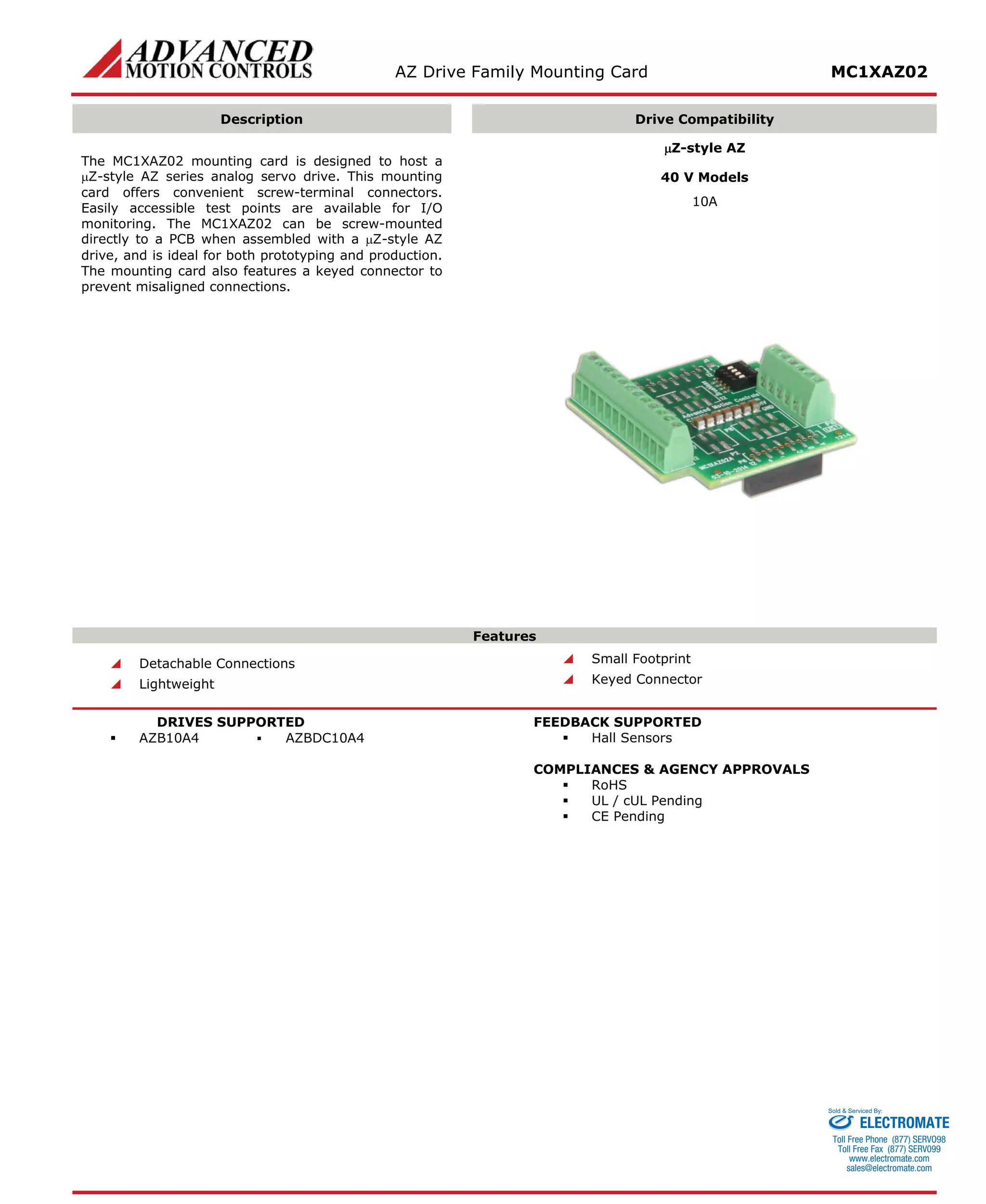
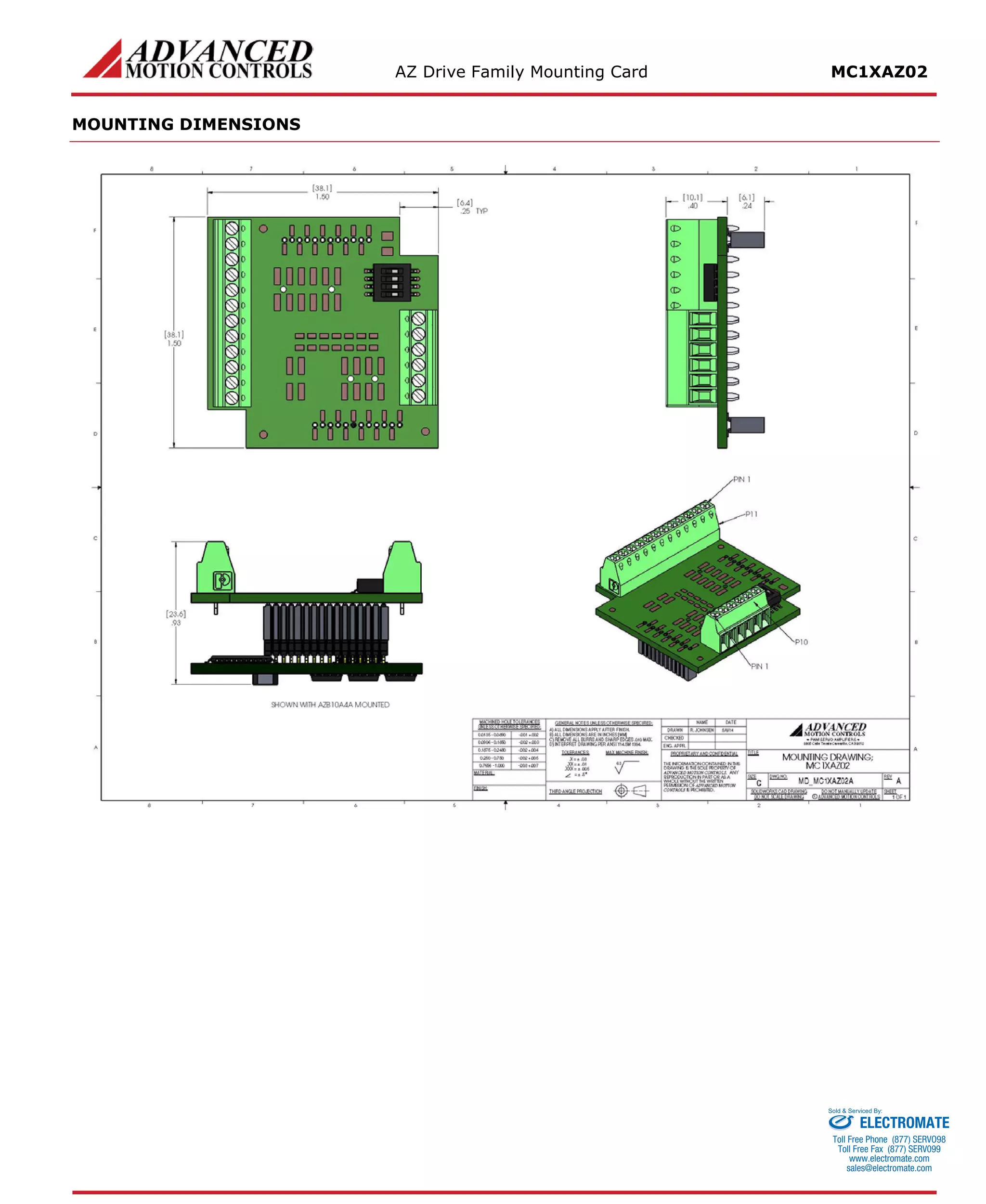

The MC1XAZ02 mounting card is designed to host μZ-style AZ analog servo drives. It provides screw terminal connectors for power and I/O and test points for monitoring. The small, lightweight card can be directly mounted on a PCB and is compatible with AZ10A4 and AZBDC10A4 drives using Hall sensors.


![Coded Agents – with UiPath SDK + LangGraph [Virtual Hands-on Workshop]](https://cdn.slidesharecdn.com/ss_thumbnails/codedagentsdeck-251215155422-5497c599-thumbnail.jpg?width=640&height=640&fit=bounds)


