This document discusses the additive manufacturing of optimized inserts for sandwich composite structures. It begins with background on traditional hot bonded inserts and their limitations. Topology optimization is then used to reduce the weight of the insert design while maintaining strength. Various optimized shapes are analyzed and a butterfly shape is found to improve thermal and structural performance. Additive manufacturing constraints are considered in the final design. Lattice structures are also analyzed and added to further reduce weight and improve thermal behavior for additive manufacturing of the optimized insert.
What are the elements of aircraft performance?
How much thrust do you need?
How fast and how slow can you fly?
#WikiCourses
http://wikicourses.wikispaces.com/Topic+Performance+of+aerospace+vehicles
Abstract:
Landing gear is one of the critical subsystems of an aircraft. The need to design landing gear with minimum weight, minimum volume, high performance, improved life and reduced life cycle cost have posed many challenges to landing gear designers and practitioners. Further it is essential to reduce the landing gear design and development cycle time while meeting all the regulatory and safety requirements. Many technologies have been developed over the years to meet these challenges in design and development of landing gear. This paper presents a perspective on various stages of landing gear design and development, current technology landscape and how these technologies are helping us to meet the challenges involved in the development of landing gear and how they are going to evolve in future.
NAME : S. Srinivasa Phani Kumar
Branch : MECHANICAL
College : SWARNANDHRA COLLEGE OF ENGINEERING & TECHNOLOGY
Crash Analysis of Front under Run Protection Device using Finite Element Anal...IOSR Journals
Under-running of passenger vehicles is one of the important parameters to be considered during
design and development of truck chassis. Front Under-run Protection Device (FUPD) plays an important role
in avoiding under-running of vehicles from front side of a truck. An explicit finite element software Altair
Radio's is used in FUPD analysis for impact loading. The deformation of FUPD bar and plastic strains in
FUPD components are determined in the impact analysis for predicting failure of the system to meet the
compliance requirements as per IS 14812-2005. Additionally, failure analysis of the FUPD attachment points
with chassis is determined. Physical testing can be reduced significantly with this approach which ultimately
reduces the total cycle time as well as the cost involved in product development.
Large scale topological optimisation: aircraft engine pylon caseAltair
An engine pylon holds the engine to the wing and ensures multiple others functions: aerodynamics, structure and systems. Moreover, it is designed to prevent a fire in the engine area from spreading to the wing. These multi-functions make the global pylon architecture design highly complex. Existing designs reach their limits regarding the aircraft performance requirements, with ever more powerful, bigger and hotter engines. Thus, the technological breakthrough becomes necessary to achieve better performance.
In the present work, we propose a new concept based on Additive Layer Manufacturing (ALM) process which eliminates many conventional constraints from the manufacturing process and can produce complex, precisely designed shapes.
Topological optimization, using ALTAIR’s finite element analysis software, is realized by integrating systems elements, fluid pipes mainly, to structural parts. Thus, these elements become structural unlike the existing design.
One objective of this work is to demonstrate the numerical feasibility of topology optimisation of large-size (5 m long, 0.83 m width and 1.19 m in height) and highly complex architecture design of an aeronautical structure.
The results show that a significant mass saving, more than 20%, can be achieved even with heavily constrained structure in terms of stresses, dimensions, interfaces, systems, etc. Furthermore, this study highlights benefits in the parts number which dropped by 97%.
Note that the existing engine pylon is made mostly of Titanium and Steel materials but for the topology optimisation a single material, Inconel 718, was chosen due to its best thermal and mechanical properties.
In order to ensure aerodynamic function, obtained organic shape structure is covered by custom-made cowls.
1/8 scale model is 3D printed by INITIAL company, using plastic material, can be exposed during the Altair Technology Conference.
Speakers
Abdelkader Salim, Innovation Engineer, SOGECLAIR Aerospace
Structural detailing of fuselage of aeroplane /aircraft.PriyankaKg4
This presentation is about the structural detailing of fuselage of aeroplane .The fuselage or body of the airplane, holds all the pieces together. The pilots sit in the cockpit at the front of the fuselage. Passengers and cargo are carried in the rear of the fuselage. Some aircraft carry fuel in the fuselage; others carry the fuel in the wings.
Design parameters of driver seat in an automobileeSAT Journals
Abstract Driver seat is an important system of any automobile, it is also complicated system consists of so many parts, adjustments as well as safety systems. A seat adjustment includes height adjustment, fore and aft adjustment, back recline adjustments. Safety systems include seat belts, air bags and advanced head restraints. Generally professional driver works more than eight hours per day of a week, therefore driver seat must be designed by considering all the parameters. Also uneven road condition induces the vibration in a vehicle transmitted to driver body. Poorly designed driver seat affects the driver health and psychological conditions of mind. Three main objectives of any driver seats are safety, health and comfort of driver. This paper presents all the parameters of driver seat such as anthropometry of human, ergonomics related parameters, seat materials, safety related parameters, comfort related parameters as well as weight and aesthetics with classifications and basics of driver seat. Keywords: Driver Seat, Comfort, Safety, Health, Adjustments.
WHY WE NEED TO DESIGN SEATS
FACTOR FOR SEAT DESIGN
GEOMETRIC FEATURES OF SEAT DESIGN
ERGONOMICS,SIMULATION AND MODELING
VIBRATION APPROACH
PRESSURE APPROACH
At Anjou Aeronautique you will encounter a distinctive tailor-made service for the cabin’s refurbishment and customization.
We are the only company in the world that provides a complete pack of products (textiles, composite products, seat belts, extensions and restraint systems) and services (design and engineering, certification, maintenance and repairs) for the cabin interiors.
International Journal of Engineering Research and Applications (IJERA) is an open access online peer reviewed international journal that publishes research and review articles in the fields of Computer Science, Neural Networks, Electrical Engineering, Software Engineering, Information Technology, Mechanical Engineering, Chemical Engineering, Plastic Engineering, Food Technology, Textile Engineering, Nano Technology & science, Power Electronics, Electronics & Communication Engineering, Computational mathematics, Image processing, Civil Engineering, Structural Engineering, Environmental Engineering, VLSI Testing & Low Power VLSI Design etc.
A Study on Thermo-Mechanical Analysis of Hot Rolling & Estimation of Residual...IOSR Journals
The major problem in rolling process is the defects like fire cracks, severe sticking in a billet mill,
and etc. This paper deals with the study on reducing or minimizing the defects of rolling process. The analysis
has been carried out for different temperature i.e. 100°c, 150°c, 200°c, 250°c. As the temperature goes on
increasing correspondingly the residual stresses decreases. Hot rolling process helps in reduced residual
stresses at high temperature & helps in formation of smooth granular structure of product. Due to the symmetry
of the rolling components, half the model is built & the analysis is carried out with 4 roller sizes varying from
8mm to 20mm with 4mm increment & the results were tabulated by using ANSYS. This will helps in estimation
of residual stresses.
Thinning and springback prediction of Mg alloy AZ31 in deep drawing process –...IJCMESJOURNAL
Magnesium is nowadays the lighter metal used in structural applications with expressive advantages over steel and aluminum. Due to its low density and high specific strength, magnesium alloys represent a promising alternative, especially for applications in automobile industry, being used in structural components in order to reduce weight and, consequently, improve fuel efficiency. In the recent decades, several researches have been performed in order to improve the use of Mg alloys in forming process since its formability is strongly affected by some conditions as temperature. In this study, a Finite Element Analysis (FEA) is performed to simulate the sheet metal deep drawing process of the magnesium alloy AZ31. The main objective is to evaluate the effect of the blank holder force and friction conditions in the formability by predicting results of springback, thickness distribution and thinning of the sheet metal blank. In total, 54 simulations were performed.
Topology optimisation of hydraulic press structureeSAT Journals
Abstract Topology optimisation is carried out to find the zones of material removal on final size optimised structure. The results are represented and density plots are presented. The zones represented by blue can be removed for better material saving. The density plots are represented showing convergence of solution rapidly in the beginning and slowly in the later iterations. Finally wolf’s law is applied for material removal and addition for better strength. After iterations, the results are presented for vonmises and displacements. The results shows a vonmises stress of around 105 N/mm2 and a displacement value of 1.457mm. The final weight is observed to be around 15501kgs. The results shows efficiency of combination of three techniques in reducing the weigh of machine structures efficiently and useful for industrial applications as a combination. All the results are represented with necessary graphical pictures. The geometry is removed based on topology optimization and results are obtained based on wolff’s law. The structural results are presented. Keywords: Topoloyg1, optimisation2, vonmises stress3, Hydraulic press4 etc…
Automatic Structural Optimization of Engine Components Using HCF and TMF Fail...IDES Editor
Modern combustion methods and the constant wish
for an increase in the specific performance results in high
thermal and mechanical loads in modern combustion engines.
In order to shorten the development time, an interactive,
simultaneous execution of design (CAD) and calculation
activities (CAE) is necessary. In this the product must be looked
at in detail and be optimized in various disciplines and in a
harmonized way of procedure to the development progress. In
the initial proactive phase the efficiency of virtual CAEmethods
is high and quickly decreases in the second half of the
development, which shows strongly reactive features. Therefore
a combined HCF (High-Cycle-Fatigue) Failure Analysis and
Optimization and TMF (Thermo-Mechanical-Fatigue) Failure
Analysis and Optimization model is discussed in this paper for
the reduction in the analysis time.
Pins require very little service and total failure seldom occurs. Wear, pitting, and scoring are the usual troubles
encountered with pins. In this paper, going to apply induction hardening process on pins and its comparison will
be done with existing pins. Different hardening thickness or case depth will be applied and analysis will be done
to interpret the results. Case depth of 1mm, 2mm or 2.5mm will be taken in induction hardening process.
Caterpillar 320dl excavator model is taken for study. Material used for the pins is EN8 grade of steel. And
different material used for the pin for analysis purpose will be bronze alloy, Titanium. The main objective in this
project is to determine the appropriate induction hardening case depth to be used in manufacturing pins.ThreedHiympeenrsmioensh
m aondde Alsn osfy sp iwnisl lu bseed u sined e xtoc aavnaatloyrz ew tihlle bsetr ecsres astteadtu uss oinng t hCea ptiianVs.5 T shoef tmwaarxei,m mumes hdienfgo rwmiallt iboen ,d monaex iumsuinmg
stress point and dangerous areas are found by the stress analysis.
Finite Element Analysis of Skirt to Dished junction in a Pressure VesselIJMER
International Journal of Modern Engineering Research (IJMER) is Peer reviewed, online Journal. It serves as an international archival forum of scholarly research related to engineering and science education.
International Journal of Modern Engineering Research (IJMER) covers all the fields of engineering and science: Electrical Engineering, Mechanical Engineering, Civil Engineering, Chemical Engineering, Computer Engineering, Agricultural Engineering, Aerospace Engineering, Thermodynamics, Structural Engineering, Control Engineering, Robotics, Mechatronics, Fluid Mechanics, Nanotechnology, Simulators, Web-based Learning, Remote Laboratories, Engineering Design Methods, Education Research, Students' Satisfaction and Motivation, Global Projects, and Assessment…. And many more.
Contact Pressure Validation of Steam Turbine Casing for Static Loading ConditionIJMER
International Journal of Modern Engineering Research (IJMER) is Peer reviewed, online Journal. It serves as an international archival forum of scholarly research related to engineering and science education.
Design and Additive Manufacturing Considerations for Liquid Rocket Engine Dev...
ADDITIVE MANUFACTURING HOT BONDED INSERTS IN SANDWICH STRUCTURES
1. ADDITIVE MANUFACTURING HOT BONDED INSERTS IN SANDWICH STRUCTURES
Marta García-Cosío (1)
, Juan Miguel González (1)
, Jeroen Vermeulen(1)
, Christian Rossmann
(2)
, Jannis Kranz (2)
(1)
Atos Spain S.A., C/ Albarracín, 25 28037 Madrid Spain, +34 91 2064151,
marta.garcia-cosio@atos.net, juan.gonzalezh@atos.net, jeroen.vermeulen2@atos.net
(2)
Materialise NV, Technologielaan 15 3001 Leuven Belgium, +32 16660406,
christian.Rossmann@materialise.be, jannis.Kranz@materialise.de
ABSTRACT
Hot bonded inserts in sandwich configurations are widely applied in spacecraft structures. These
inserts are co-cured with the composite structure sandwich panels and are commonly used for
highly loaded interfaces. The large capability to transmit the load is directly related to the bonded
area which connects the insert and the skins of the sandwich structure.
The inserts are commonly made of aluminium alloy since the mass of this interface solution is an
important design parameter. On the other hand, the thermo-elastic stresses which occur during the
curing process can affect the insert´s strength capability. That is why for Carbon Fibre Reinforced
Plastic (CFRP) skin sandwiches, titanium hot bonded inserts are chosen to reduce this negative
thermo-elastic effect.
Additive Manufacturing (AM) provides the opportunity to improve this kind of structural elements
in three main areas: mass, thermo-elastic behaviour and bonding capability. AM opens a new way
of thinking and defining design solutions; facing new material properties directly dependent of the
manufacturing process, topology optimization of the part as the main design driver and different
manufacturing limitations depending on the corresponding technology.
The result of the design optimization can be introduced into part manufacturing with relatively few
manufacturing limitations. In this case, topology optimization is used to reduce weight in
combination with maintaining the strength of the part. Different lattice structures are also studied to
improve the design.
This study shows a complete design loop with the subsequent additive manufacturing of an
optimized aerospace part, combining the optimization and FEM analysis with the manufacturing
requirements inherent to the relatively new fabrication method.
1. INTRODUCTION
1.1 Background
Hot bonded inserts in sandwich spacecraft structures are currently limited in their geometrical shape
mainly because of traditional manufacturing procedures. Aluminium or titanium alloy inserts
generally have block-shapes as they are manufactured by machining. They are usually completely
solid, which increases the mass and has a higher stiffness than strictly necessary. The bonding area
is one of the main design-drivers of the insert, since a larger bonding surface will increase the load
transfer capability.
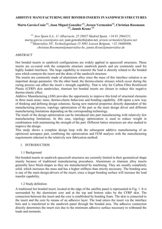
1.2 Study definition
A traditional hot bonded insert, located at the edge of the satellite panel is represented in Fig. 1. It is
surrounded by the aluminium core and at the top and bottom sides by the CFRP skin. The
connection between the insert and the core is established by bonding foam. The skin is connected to
the insert and the core by means of an adhesive layer. The load enters the insert via the interface
bots and is transferred to the sandwich panel through the bonded area. The adhesive connection
directly determines the insert size due to the minimum adhesive surface necessary to withstand the
loads and moments.
2. Fig. 1 Representation of a traditional insert configuration in a sandwich panel
1.3 Traditional method for structural analysis
The current hot bonded insert preliminary design is traditionally determined by an analytical
calculation. In a first approach, the inserts are designed to withstand the failure of the skin, the core
and the adhesive, neglecting any other failure source (such as the insert itself).
In-plane loads are the main cause of skin de-bonding, which is usually the predominant failure
mode and the first being analysed. Together with in-plane forces and moments, drilling moments
are also considered. Bending moments (in-plane) are relevant as they are reacting on both faces of
the insert as a shear load. The bonding surface is determined (neglecting adhesive peeling failure),
resulting in the overall size of the insert.
Based on the previous dimensions derived from the bonding analysis, skin and core rupture are
analysed. In general, out of plane loads are resisted by the
core and in-plane loads are absorbed by the skins. Bending
moments and pull out forces applied on the insert edge can
result in the necessity of core reinforcements or an overall
size increase of the insert.
The analyses of the skin take into account both in-plane
moments and forces. Even when these forces and moments
could be absorbed by the skin as shear stresses, this
contribution is considered as marginal and only failure due
to tension and compression of the skin is taken into account.
In plane forces transferred through the adhesive to the skin
also induce a tension-compression state and the maximum stress in the skin extends over the insert
edge, see Fig. 2, where α is the opening angle of the shear stress contribution (typically 20 degrees).
This analysis is meant to verify the skin integrity or to define the need for redesign by means of skin
reinforcements around the hot bonded insert or a change in the overall dimensions of the insert.
The described traditional methodology neglects several failure modes (of which experience shows
as not critical) and it is limited to a typical insert configuration. New complex designs will require
new analysis methods in order to assure the robustness of the product.
2. REQUIREMENTS
The objective of this study is to design and manufacture a new insert with three improved
characteristics: less weight, better thermo-elastic behaviour and an improved bonding capability.
The design will be focussed on metal AM, which offers a high geometrical freedom. In contrast to
many other manufacturing processes the part costs are primarily depending on the printed volume
and not on the part complexity. The new design will pursue the reduction of the thermo-elastic
deformations. In parallel, lattice structures, which can be manufactured by additive techniques, can
contribute to improve the insert weight and the part stability during the manufacturing process.
The loads and moments applied in this study are derived from a real-life insert application in the
hoisting points of a heavy satellite. During the study, fatigue is not taken into account since the
Fig. 2 Pull-out forces stress
distribution in the skin
3. insert is loaded only during Assembly, Integration and Test (AIT) operations which will take place
just a very limited amount of times [1]. The two most critical load cases are selected for the
mechanical analysis, which cover the entire load envelope (see Table 1).
Table 1. Load cases used in the mechanical analysis
Load Case Fz (N) Fy (N) Fx (N) Mx (Nm) My (Nm) Mz (Nm)
LC-1 5112 52697 128095 1327 0 734
LC-2 1889 37774 85488 3386 0 557
Due to different thermal expansion coefficients of the materials, during the curing process, stresses
are generated between the parts and could affect the load capability. The curing process of the insert
in the panel is simulated by a thermo-elastic analysis applying a uniform temperature decrease from
120ºC to 20ºC. The scope of this analysis is to determine the relative improvement with respect to
the original design, not to obtain quantitative data about the stresses during the curing process.
The applied material properties are shown in Table 2.
Table 2. Material properties of the parts involved in the analysis
Part Material E (GPa) G (GPa) Υ α (1/ºC) at 20ºC ρ (kg/m3
)
Insert Titanium 110.5 42.5 0.31 8.78E-06 4410
Core Aluminium 0.6 0.375 0.29 2.38E-05 91.3
Skin CFRP 110.43 30.28 0.247 -1.01E-07 1650
The detailed Abaqus FEM models used during the virtual validation process contain the full ply
representation of the CFRP skin and an incorporated failure mode for the adhesive material.
3. DESIGN
3.1 Topology optimization
Based on the original insert design (square box shape,Fig. 1), a topological optimization has been
performed as per [2] and [3]. The insert design space during the optimization is based on the
original volume to maintain the bonding surfaces. The optimization can be divided in two main
strategies; one is to establish the maximum part stiffness with a corresponding user-defined volume
and the other is a volume reduction respecting the minimum user-defined displacement. The
optimization objectives and design constraints are shown in Table 3.
Table 3. Optimization strategy based on the square-box insert
Model version V01 V02 V03 V04 V05 V06
Objective
Min.
compliance
Min.
compliance
Min.
compliance
Min. volume Min. volume Min. volume
Design constraint
20% of
volume
30% of
volume
40% of
volume
Max.
displacement
at ref. point
0.3mm
Max.
displacement
at ref. point
0.4mm
Max.
displacement
at ref. point
0.5mm
The topological optimization, which is based on the loads envelope, will determine the load paths
and in this way the design can be adjusted to obtain a lightweight structure fulfilling the structural
requirements. The following graphs show the results of the topology optimization loops.
4. Fig. 3 Results of topology optimization Fig. 4 Results of topology optimization
This kind of graphs usually shows a typical distribution; some design solutions have a significantly
reduced mass but their reduced stiffness will result in structural failure (results in the upper left area
of Fig. 4). The design options indicated by the red oval in Fig. 3 and Fig. 4 respect the minimum
structural requirements in combination with a significant mass reduction. Within these most
interesting options, design version V02 is considered the optimum topology optimized insert design
showing a theoretical mass reduction of 70% and respecting the structural requirements.
Fig. 5 Topology optimized insert design Fig. 6 Topology optimized insert design
The topology optimized design is shown in Fig. 5. Fig. 6 shows the conversion of the optimization
result (light blue) into a parametrised CATIA model (orange). The material distribution respects an
improved load path within the insert. Mass is concentrated around the mounting holes and the upper
and lower bonding areas, since load intends to pass through the insert to the skin via the shortest
distance. Although the remaining area of the insert is necessary to respect the required bonding
area, it can be completely hollow to reach an optimum mass reduction.
3.2 Shape optimization
The topology optimization is focussed on the internal volume of the insert. The subsequent shape
optimization is performed to improve the stress distribution in the joint with the sandwich panel.
The shapes have been selected based on the stress concentration areas indicated by the FEM
analyses and focus on the reduction of the critical areas with high stresses.
Five different insert shapes have been analysed in detail;
Fig. 7 Original; the original insert design.
Fig. 8 V02-OPT01, the optimum topology optimized design.
Fig. 9 Circle V05-02; an angular solid shape.
Fig. 10 Gothic V06-02; an additional circle on top of the angular solid shape to reduce
rotation.
Fig. 11 Butterfly V04-05; a double angular solid shape.
Fig. 12 Butterfly V04-03; a double angular hollow shape.
5. Fig. 7 Original Fig. 8 V02-OPT01 Fig. 9 Circle V05-02
Fig. 10 Gothic V06-02 Fig. 11 Butterfly V04-05 Fig. 12 Butterfly V04-03
Each insert shape design option is analysed within the complete assembly by means of a detailed
Abaqus FEM model. The curing process of the insert within the assembly is simulated by a thermal
analysis applying a uniform temperature decrease from 120ºC to 20ºC. Fig. 13 contains the micro-
strain levels which occur in the CFRP skin, which clearly shows the improvements obtained in each
design option.
Fig. 13 Elastic strain level in skin (thermal analysis)
Besides the thermal behaviour also the structural requirements are analysed applying the before
mentioned load cases. It can be concluded that design option “Butterfly V04-03” is the optimum
shape optimization solution based on its thermal and structural behaviour. The butterfly shaped
design results in a significant improvement in the micro-strain level in the skin, which is a good
indicator of the effectiveness of the design.
3.3 Design and Manufacturability
Once the topology and shape optimization process is finished, the final insert design needs to be
adapted according to mechanical requirements which are not covered in the optimization process.
For the AM process adapted design as shown in Fig. 14, additional changes in the design are
implemented since the process restrictions differ from conventional manufacturing processes due to
the layer-wise build-up of the parts. A part design adapted to the production process is a necessity in
order to assure a good manufacturability [4].
6. One of the biggest differences between AM and conventional manufacturing processes is the need
for support structures. The goal for the design of the insert was to keep the post machining efforts at
a low level in order to minimize manufacturing costs and assure a high repeatability in the
manufacturing process outcome. The defined build up strategy is shown in Fig. 15 and Fig. 16.
Fig. 14 AM-prepared and optimized
design
Fig. 15 Build orientation Fig. 16 Build
orientation
An avoidance of supports in the inner structure is achieved by using a triangular shape of the upper
part section that considers the critical overhang angle of 45° to the build plate, as shown in Fig. 17
and Fig. 18. The down facing area as well as the bonded side walls are modelled with an offset in
order to assure later post machining according to the part demands on accuracy. These three
surfaces and the threads in the bore are the only interfaces that need to be post machined.
Fig. 17 Critical
overhang
Fig. 18 Internal support to
prevent overhang problems
Fig. 19 Powder removal holes
Powder removal is achieved by holes in the lower surface that assure the accessibility to the part´s
hollow section when built up and still connected to the building platform, as shown in Fig. 19.
In order to reduce the possibility of a part failure or the appearance of cracks due to thermally
induced stresses in the manufacturing process, the part is moreover designed in such a way that
sharp corners are mostly avoided. The final design for manufacturing will be referred to as INSERT
1 and its weight data are shown in Table 4. The mass reduction with respect to the original insert
design amounts 62% taking into account all manufacturing related constraints, which only adds 45
grams to the design without manufacturing constraints.
Table 4 Weight comparison
Original
Design without manufacturing
constraints
Design with manufacturing
constraints
Weight (gr) 1464 517 562
Weight Reduction (gr) -- 947 902
Percentage of reduction -- 65% 62%
7. 4. LATTICE STRUCTURE DESIGN
Based on the manufactured INSERT 1, an additional design loop is performed to improve the
manufacturing process and cost. The goal of this phase is to reduce the post-process machining
operation of the bonding area. Lattice structures are used to stabilize the surfaces during the
manufacturing process, with an additional improvement in thermo-elastic distortion of the outer
surfaces.
4.1 Lattice structure design
In this new design, the insert outer shape is maintained; the external shape corresponds to the
butterfly geometry obtained during the shape optimization.
The lattice structures refer to a specific type of meso-structures that consists of small beam
elements. The versatility of AM allows the fabrication of these complex unit cell lattice structures
which can be used as “basic design blocks” to generate macro-scale geometries [5].
The design concept is based on the hollow butterfly shaped insert, with walls at the adhesive
surfaces as thin as possible, and with material around the screw threads. The insert´s interior
volume is filled with a uniform cellular lattice structure.
The lattice cell selection is based on the manufacturing method Selective Laser Melting [6] [7].
From the three basic cellular designs shown in Fig. 20 to Fig. 22, the X-shaped cell design 1 (Fig.
20) is selected since it provides the optimum combination of structural behaviour and mass
reduction.
Fig. 20 Cell design 1 Fig. 21 Cell design 2 Fig. 22 Cell design 3
Based on the chosen X-shaped cell, the adequate cell size and the bar diameter need to be
determined [8]. These parameters are obtained by FEM analyses changing the cell size in
combination with different bar diameters and applying the mechanical load cases. Apart from the
theoretical analysis, practical manufacturing requirements and powder removal also need to be
respected. The lattice structure needs to be able to support the mechanical stresses once assembled
and the thermo-elastic stresses during the curing process. The mechanical stresses are used to
dimension the cell. The results of the mechanical analysis stresses can be seen in Fig. 23.
Fig. 23 Stress level lattice structure Fig. 24 Detailed lattice structure (CAD)
The further away from this bolt area, the lower the stress level is in the lattice bars. Taking into
account this stress distribution, the lattice bars are provided with a variable diameter to assure the
structural integrity. Thus a variable bar diameter between 2.3 mm in the area of the bolt holes and
1.0 mm at the rear is applied, as can also be seen in Fig. 24.
8. Fig. 25 shows the variation of weight in each lattice configuration versus the maximum
displacement of the insert in the assembly. Fig. 26 shows the maximum bar stresses versus the
lattice weight. It indicates that it is more effective to increase the bar diameter than to increase the
cell dimensions. The most effective combination is a lattice cell with size 10x8x8 mm, as indicated
by the dashed green oval in Fig. 25 and Fig. 26.
Fig. 25 Relation lattice weight - displacement Fig. 26 Relation lattice weight – stress level
In the FEM analysis the lattice structure is represented by bar elements. As a direct consequence,
the possible stress peaks at the connection nodes of the bars are not taken into account. The bar
connection nodes contain the highest stress levels, as referred in [9]. To determine these critical
stresses, a detailed non-linear FEM analysis is performed to define the adequate fillet radius to
respect the yield strength of the lattice material Ti6Al4V. Furthermore the weight influence needs to
be taken into account, since an increased bar diameter results in additional mass.
The study is focussed on the most critical lattice connection node. This node is modelled in detail
and the loads from the general FEM model are applied. The range of the connection node radius is
between 0.0 mm and 1.2 mm. The results of all the analysed fillet radii are shown in Fig. 27. In the
final lattice design a fillet radius of 0.6 mm is applied since it shows allowable peak stress values in
combination with an acceptable corresponding weight. The typical Von Mises stress distribution in
the connection node with a fillet radius of 0.6 mm can be seen in Fig. 28.
Fig. 27 σ in connection node as function of Rfillet Fig. 28 Detailed FEM model of lattice node
9. The final design for INSERT 2 is shown in Fig. 29 and Fig. 30. It has an external shape equal to
INSERT 1 as mentioned before, but with thinner surrounding walls and an internal X-shape graded
cellular structure with a cell size of 11.3x7.5x8.5mm. Fig. 31 shows the detail of the smooth lattice
integration into the outer insert volume.
Fig. 29 Final design INSERT 2 Fig. 30 Final design INSERT 2 Fig. 31 Detail design
INSERT 2
4.2 Design and manufacturability
IINSERT 2 shares the same basic manufacturing orientation
and strategy as INSERT 1. The down facing interface which
has the four bolt holes is orientated downwards towards the
build plate. The up-facing structure segments are designed
in such a way that no support structures are necessary. All
surfaces show an orientation of 45° with the build plate and
do not need any support. The wall thickness was set to the
minimum recommended value for manufacturing in order to
assure a stable part build up. In contrast to INSERT 1, the
internal volume of INSERT 2 is filled with a lattice
structure. Fig. 32 shows the lattice structure as a printed trial
version.
An easy powder removal after the building process is
guaranteed by top and down facing bores that allow access
to the inner volume of the insert.
Table 5 shows the weight comparison between INSERT 1
and INSERT 2.
Table 5 Weight comparison
Weight comparison* INSERT 1 INSERT 2
Weight (gr) 562 508
Weight Reduction (gr) -- 54
Percentage of reduction -- 10%
*Reference weight of original insert amounts 1464 gr.
Fig. 32 Manufactured lattice structure
10. 5. PART MANUFACTURING
5.1 Manufacturing process
Fig. 33 describes the process chain for the insert’s manufacturing by metal AM. The manufacturing
process strongly depends on a digital part model. During the part data creation phase a STL-file
(standard triangulation language) is generated on the basis of the parametric CAD model. The STL-
file format describes the part surfaces by a tessellation of its surface. During the manufacturing pre-
process phase the part is orientated with respect to the build plate.
Based on the part orientation, the support structures are defined. The part and the corresponding
manufacturing support structures are sliced for the manufacturing process according to the material
and the machine dependent layer thickness. The data containing the layer information of the part
and the support structures is then transferred to the manufacturing machine. Typically, the process
parameter definition is then defined on the machine before the actual manufacturing process starts.
Fig. 33 Process chain for metal AM
During manufacturing, phenomena like melting of the powder particles, melt pool solidification and
thermal shrinkage during cooling leads to thermally induced stresses in the part. After fabrication a
heat treatment is performed as part of the post-processing campaign in order to achieve a stress
relief. In order to meet part demands on accuracy as well as surface roughness a post machining was
necessary. Typical accuracies as built are 0.2 mm as a lower boundary. Therefore, after part
removal from the machine build plate, shape cutting and support removal is performed according to
the parts technical requirements. Both insert design options are manufactured, the successfully
manufactured and post machined INSERT 1 is shown in Fig. 34 to Fig. 36.
Fig. 34 Manufactured INSERT 1 Fig. 35 Manufactured INSERT 1 Fig. 36 Detail
INSERT 1
11. 6. VALIDATION AND VERIFICATION
6.1 Dimensional validation
Functional parts must fit into the system environment they are designed for. In order to assure that
the result of post processing INSERT 1 is in accordance with the part requirements, a 3D scan of
the part is conducted. The equipment used is a GOM ATOS IIe with a measurement accuracy of
0.02 mm. The critical feature was the planarity of 0.05 mm and the overall maximum interface
thickness deviation of -0.2 to -0.3 mm of the part. Fig. 37 shows the drawing with the dimensional
requirements and Fig. 38 contains the results of the 3D scan of INSERT 1.
Fig. 37 Drawing INSERT 1 Fig. 38 3D scan results INSERT 1
The result of the measurements shows that the post-machined part fulfils the accuracy demands
according to the specified part requirements.
Table 6 shows the relation between the theoretical weight according to the CAD info and the final
manufactured part weight.
Table 6 weight data INSERT 1
Insert
Original
Insert Type 1 (CAD)
Insert Type 1
(manufactured)
Weight (gr) 1464 562 560
Weight Reduction (gr) -- 902 904
Percentage of reduction -- 62% 62%
6.2 Structural validation
A virtual structural validation has been performed by means of a detailed FEM analysis in Abaqus
version 2016 for the thermomechanical and mechanical load cases. The final design options with
and without lattice structure are compared with the original design [10], [11].
The detailed FEM model (Fig. 39) represents the skin
with composite shell elements containing the laminar
plies. The adhesive layers are represented with solid
cohesive elements taking into account a failure criterion
which respects the maximum allowed stress according
to manufacturer´s material data.
In case of INSERT 2, the lattice structure is modelled
with solid tetrahedral elements in the most critical area
and the remaining lattice structure is modelled by beam
elements.
Fig. 39 Abaqus detailed FEM model
12. With respect to the thermal analysis, which represents the adhesive curing process by a uniform
temperature decrease from 120ºC to 20ªC, the micro strain values in the skin clearly represent the
obtained thermal improvements as shown in Fig. 40. The adhesive shows similar improvement
results and the insert itself reveals higher stress levels in the modified lattice version, but far below
the yield strength level of the applied titanium alloy Ti6Al4V (860MPa).
Fig. 40 Elastic strain level in skin (thermal load)
The mechanical analysis, with the application of forces and moments on the assembly, also shows
improvements in the behaviour of the skin despite the significant mass reduction. In Fig. 41 can be
seen that the logarithmic strain peak values in the skin as well as the critical area are reduced.
Fig. 41 Logarithmic strain level in skin (mechanical load)
Generally the optimization process pushes the part design more in the direction of the allowable
stress, reducing the safety margin. The results of this study are a clear example of this statement,
since the achieved mass reductions of INSERT 1 and 2 are related with an increased level of Von
Mises stress, as can be seen in Fig. 42.
13. Fig. 42 Von Mises stress level in insert (mechanical load)
According to the adhesive material data sheet provided by the manufacturer, the stress resistance up
to failure amounts 20 MPa. This value is implemented in the FEM model and Fig. 43 shows the
results of the corresponding quadratic nominal stress damage initiation criterion (QUADSCRT). In
case the QUADSCRT output value exceeds the dimensionless limit of 1.0, the element is supposed
to fail. It can be observed that both modified design options show a clear failure improvement for
the adhesive, as well in maximum value as failure area. The insert version with lattice shows a
slightly increased failure area compared to the version without lattice due to slightly higher insert
flexibility.
Fig. 43 Nominal stress damage in adhesive (mechanical load)
14. 7. CONCLUSIONS AND NEXT STEPS
Additive Manufacturing provides the opportunity of improving the hot bonded insert design in
several areas. The first one is a mass reduction of 65%, the new insert saves more than 0.9 kg which
is a significant improvement for a spacecraft device. The thermo-elastic behaviour is improving as
well due to a more flexible insert. The microstrain levels in the CFRP skin are significantly
decreased compared to the original design.
The strength capability of the panel is improved by obtaining a better stress distribution therefore
the adhesive damage area is drastically reduced.
In terms of costs, the mass reduction is a direct production material cost saver, and additionally it
reduces the total weight of the satellite with the related transport cost improvements.
Although the improvements and opportunities achieved with optimization and subsequent metal
AM are huge, some challenges need to be solved. Since the insert contains an internal structure,
proper inspection and verification procedures (e.g. tomography) need to be used to check geometry
and defects. Besides, mechanical testing needs to be performed to validate and qualify the design
concepts. Finally, to assure repeatability in production, manufacturing process parameters will be
defined and process monitoring systems need to be implemented.
As a further development, new strategies can be developed to improve the existing joints between
the insert and the CFRP panels. In particular, advanced hybrid joints, which incorporate a specially
designed array of macro-scale pins over the metallic part, have shown promising results in
increasing the strength of interfaces [12]. One of the most relevant advantages of this technique is
the fact that the pins can be inserted in the CFRP material before the curing process. Moreover the
SLM technique used in this study can be used for the in-situ fabrication of pins on the outer surfaces
of the insert, due to high accuracy and dimensional tolerance. This can replace the conventional
welding operations used to assemble the pins. The insert provided with pins can be produced in a
single operation and subsequently assembled with the skin by co-curing. Besides the manufacturing
and assembly improvements, this concept changes the design philosophy drastically by offering the
possibility to reduce the adhesive surfaces and thus, the complete insert design reducing insert
volume, and as a consequence, further reduction in weight and costs.
15. 8. REFERENCES
[1] Wycisk, Eric, et al. Effects of defects in laser additive manufactured Ti-6Al-4V on fatigue
properties. Physics Procedia 56 (2014): 371-378.
[2] D. Brackett., et al. Topology optimization for additive manufacturing, Leicestershire, August
2011.
[3] M.P.Bendsoe, O. Sigmund. Topology Optimization, Theory, Methods and Applications,
Denmark, 2002.
[4] Kranz, J., D. Herzog, and C. Emmelmann. Design guidelines for laser additive manufacturing of
lightweight structures in TiAl6V4. Journal of Laser Applications 27.S1 (2015): S14001.
[5] Dr. David Rosen, et al. Design of general lattice structures for lightweight and compliance
applications, Loughborough University, July 2006.
[6] Leary M., et al. Selective laser melting (SLM) of AlSi12Mg lattice structures, Materials and
Design 98, 344–357, 2016.
[7] Vivien J. Challis, et al. High specific strength and stiffness structures produced using selective
laser melting, Elsevier, July 2014.
[8] Jason Nguyen., et al. Conformal Lattice Structure Design and Fabrication, Georgia Institute of
Technology, October 2012.
[9] Wang K., et al. Designable dual-material auxetic metamaterials using three-dimensional
printing, Elsevier, 2014.
[10] C. Rossmann, T. Craeghs, S. Cornelissen, W. Van Paepegem, L. Farkas. Integrating
Simulation of Lightweight Structures into the Product Development Process of Metal Additive
Manufacturing. NAFEMS World Conference, San Diego, CA, 2015.
[11] C. Rossmann, T. Craeghs. Simulation of Lightweight Designs Fabricated by Metal Additive
Manufacturing. NAFEMS DACH, Bamberg, GER, 2016.
[12] Graham D.P., et al. The development and scalability of a high strength, damage tolerant,
hybrid joining scheme for composite–metal structures, Elsevier, 2014.