This document proposes a new millimeter-wave non-orthogonal multiple access (mmWave-NOMA) transmission scheme for cellular machine-to-machine (M2M) communications to support massive connectivity and low latency for Internet of Things applications. It considers downlink transmission where multiple MTC devices share communication resources. Three MTC device pairing schemes are introduced based on the distance between devices and base station: 1) random near and far devices, 2) nearest near and far devices, 3) nearest near and farthest far devices. The performance of the schemes is analyzed by deriving expressions for outage probability and sum rate. Analysis and simulations show the proposed system improves outage probability over mmWave with orthogonal multiple access schemes.
![2327-4662 (c) 2018 IEEE. Personal use is permitted, but republication/redistribution requires IEEE permission. See http://www.ieee.org/publications_standards/publications/rights/index.html for more information.
This article has been accepted for publication in a future issue of this journal, but has not been fully edited. Content may change prior to final publication. Citation information: DOI 10.1109/JIOT.2018.2819645, IEEE
Internet of Things Journal
1
Millimeter-Wave NOMA Transmission in Cellular
M2M Communications for Internet of Things
Tiejun Lv, Senior Member, IEEE, Yuyu Ma, Jie Zeng, Senior Member, IEEE, and P. Takis Mathiopoulos, Senior
Member, IEEE
Abstract—Massive connectivity and low latency are two impor-
tant challenges for the Internet of Things (IoT) to achieve the
Quality of Service (QoS) provisions required by the numerous
devices it is designed to service. Motivated by these challenges,
in the paper we introduce a new millimeter-wave non-orthogonal
multiple access (mmWave-NOMA) transmission scheme designed
for cellular machine-to-machine (M2M) communication systems
for IoT applications. It consists of one base station (BS) and
numerous multiple machine type communication (MTC) devices
operating in a cellular communication environment. We consider
its down-link performance and assume that multiple MTC
devices share the same communication resources offered by
the proposed mmWave-NOMA transmission scheme, which can
support massive connectivity. For this system, a novel MTC
pairing scheme is introduced the design of which is based upon
the distance between the BS and the MTC devices aiming at
reducing the system overall overhead for massive connectivity
and latency. In particular, we consider three different MTC
device pairing schemes, namely i) the random near and the
random far MTC devices (RNRF); ii) the nearest near and
the nearest far MTC devices (NNNF); and iii) the nearest
near and the farthest far MTC device (NNFF). For all three
pairing schemes, their performance is analyzed by deriving
closed-form expressions of the outage probability and the sum
rate. Furthermore, performance comparison studies of the three
MTC device pairing schemes have been carried out. The va-
lidity of the analytical approach has been verified by means
of extensive computer simulations. The obtained performance
evaluation results have demonstrated that the proposed cellular
M2M communication system employing the mmWave-NOMA
transmission scheme improves outage probability as compared
to equivalent systems using mmWave with Orthogonal Multiple
Access (OMA) schemes.
Index Terms—Internet of Things (IoT), millimeter-wave
non-orthogonal multiple access (mmWave-NOMA), machine-to-
machine (M2M), MTC device pairing schemes, outage probabil-
ity.
I. INTRODUCTION
Through the development of numerous applications, the
Internet of Things (IoT) [1], [2] aims at providing a host of
new services to citizens, private and public companies as well
as to governmental administrations [3]–[5]. In general, it is
envisioned that the IoT will provide a platform which will
The financial support of the National Natural Science Foundation of China
(NSFC) (Grant No. 61671072) is gratefully acknowledged.
T. Lv, Y. Ma and J. Zeng are with the School of Information and
Communication Engineering, Beijing University of Posts and Telecom-
munications (BUPT), Beijing 100876, China (e-mail: {lvtiejun, mayy,
zengjie}@bupt.edu.cn).
P. T. Mathiopoulos is with the Department of Informatics and Telecommu-
nications, National and Kapodistrian University of Athens, Athens 157 84,
Greece (e-mail: mathio@di.uoa.gr).
connect a huge number of devices in order to gather, share
and forward information between devices as well as their
users [6]–[8]. It is estimated that by the year 2020 almost
50 billion of devices will connected to this platform [9].
To accommodate the drastically increasing number of these
devices, the resulting huge increase in data traffic will have a
great impact on the design and implementation of 5th Genera-
tion (5G) wireless communication systems. In particular, there
will be challenging requirements for their efficient operation,
including massive connectivity and low latency [10], [11]. On
the one hand, machine-to-machine (M2M) communications
have been regarded as one of the promising new technologies
to realize IoT employing the 5G network [12]. M2M com-
munication systems realize automated data communications
among machine type communication (MTC) devices thus
constituting the basic communication infrastructure for the
emerging IoT [13], [14]. In addition, Long Term Evolution
(LTE) for MTC (LTE-M) and narrow band IoT (NB-IoT) have
been proposed on top of existing cellular standards, which
can provide reliable solutions for M2M communications [15].
On the other hand, non-orthogonal multiple access (NOMA),
which has been proposed as a multiple access scheme to
be employed with 5G wireless communication systems, has
the ability to support massive connectivity by means of non-
orthogonal resource allocation while simultaneously reducing
latencies by its grant-free scheduling. For example, in [16], an
interesting power-domain user multiplexing scheme for future
radio access has been proposed. Note that the superposition
code (SC) at the transmitter side and successive interference
cancellation (SIC) at the receiver side are widely considered
in the papers with NOMA transmission [16]–[20].
As opposed to orthogonal multiple access (OMA) schemes,
NOMA can support many users via non-orthogonal resource
allocation, i.e., multiple users can be served at the simul-
taneously at the time, frequency and code domains as well
as being multiplexed at different power levels [21]–[23]. For
example, under poor channel conditions, users are allocated
more transmission power as compared to users operating under
better channel conditions [24]–[26]. Such an approach clearly
improves the communication systems’ overall fairness. It is
noted that since users within one group share the available in
the group communication resources, user grouping strategies
can significantly influence the overall NOMA system perfor-
mance [27], and thus it is necessary to carefully study user
scheduling schemes [28]–[31].
Due to the high demand of bandwidth required to sup-
port significantly increased data rates, the use of NOMA to](https://image.slidesharecdn.com/lv2018-190814055207/85/Lv2018-1-320.jpg)
![2327-4662 (c) 2018 IEEE. Personal use is permitted, but republication/redistribution requires IEEE permission. See http://www.ieee.org/publications_standards/publications/rights/index.html for more information.
This article has been accepted for publication in a future issue of this journal, but has not been fully edited. Content may change prior to final publication. Citation information: DOI 10.1109/JIOT.2018.2819645, IEEE
Internet of Things Journal
1
Millimeter-Wave NOMA Transmission in Cellular
M2M Communications for Internet of Things
Tiejun Lv, Senior Member, IEEE, Yuyu Ma, Jie Zeng, Senior Member, IEEE, and P. Takis Mathiopoulos, Senior
Member, IEEE
Abstract—Massive connectivity and low latency are two impor-
tant challenges for the Internet of Things (IoT) to achieve the
Quality of Service (QoS) provisions required by the numerous
devices it is designed to service. Motivated by these challenges,
in the paper we introduce a new millimeter-wave non-orthogonal
multiple access (mmWave-NOMA) transmission scheme designed
for cellular machine-to-machine (M2M) communication systems
for IoT applications. It consists of one base station (BS) and
numerous multiple machine type communication (MTC) devices
operating in a cellular communication environment. We consider
its down-link performance and assume that multiple MTC
devices share the same communication resources offered by
the proposed mmWave-NOMA transmission scheme, which can
support massive connectivity. For this system, a novel MTC
pairing scheme is introduced the design of which is based upon
the distance between the BS and the MTC devices aiming at
reducing the system overall overhead for massive connectivity
and latency. In particular, we consider three different MTC
device pairing schemes, namely i) the random near and the
random far MTC devices (RNRF); ii) the nearest near and
the nearest far MTC devices (NNNF); and iii) the nearest
near and the farthest far MTC device (NNFF). For all three
pairing schemes, their performance is analyzed by deriving
closed-form expressions of the outage probability and the sum
rate. Furthermore, performance comparison studies of the three
MTC device pairing schemes have been carried out. The va-
lidity of the analytical approach has been verified by means
of extensive computer simulations. The obtained performance
evaluation results have demonstrated that the proposed cellular
M2M communication system employing the mmWave-NOMA
transmission scheme improves outage probability as compared
to equivalent systems using mmWave with Orthogonal Multiple
Access (OMA) schemes.
Index Terms—Internet of Things (IoT), millimeter-wave
non-orthogonal multiple access (mmWave-NOMA), machine-to-
machine (M2M), MTC device pairing schemes, outage probabil-
ity.
I. INTRODUCTION
Through the development of numerous applications, the
Internet of Things (IoT) [1], [2] aims at providing a host of
new services to citizens, private and public companies as well
as to governmental administrations [3]–[5]. In general, it is
envisioned that the IoT will provide a platform which will
The financial support of the National Natural Science Foundation of China
(NSFC) (Grant No. 61671072) is gratefully acknowledged.
T. Lv, Y. Ma and J. Zeng are with the School of Information and
Communication Engineering, Beijing University of Posts and Telecom-
munications (BUPT), Beijing 100876, China (e-mail: {lvtiejun, mayy,
zengjie}@bupt.edu.cn).
P. T. Mathiopoulos is with the Department of Informatics and Telecommu-
nications, National and Kapodistrian University of Athens, Athens 157 84,
Greece (e-mail: mathio@di.uoa.gr).
connect a huge number of devices in order to gather, share
and forward information between devices as well as their
users [6]–[8]. It is estimated that by the year 2020 almost
50 billion of devices will connected to this platform [9].
To accommodate the drastically increasing number of these
devices, the resulting huge increase in data traffic will have a
great impact on the design and implementation of 5th Genera-
tion (5G) wireless communication systems. In particular, there
will be challenging requirements for their efficient operation,
including massive connectivity and low latency [10], [11]. On
the one hand, machine-to-machine (M2M) communications
have been regarded as one of the promising new technologies
to realize IoT employing the 5G network [12]. M2M com-
munication systems realize automated data communications
among machine type communication (MTC) devices thus
constituting the basic communication infrastructure for the
emerging IoT [13], [14]. In addition, Long Term Evolution
(LTE) for MTC (LTE-M) and narrow band IoT (NB-IoT) have
been proposed on top of existing cellular standards, which
can provide reliable solutions for M2M communications [15].
On the other hand, non-orthogonal multiple access (NOMA),
which has been proposed as a multiple access scheme to
be employed with 5G wireless communication systems, has
the ability to support massive connectivity by means of non-
orthogonal resource allocation while simultaneously reducing
latencies by its grant-free scheduling. For example, in [16], an
interesting power-domain user multiplexing scheme for future
radio access has been proposed. Note that the superposition
code (SC) at the transmitter side and successive interference
cancellation (SIC) at the receiver side are widely considered
in the papers with NOMA transmission [16]–[20].
As opposed to orthogonal multiple access (OMA) schemes,
NOMA can support many users via non-orthogonal resource
allocation, i.e., multiple users can be served at the simul-
taneously at the time, frequency and code domains as well
as being multiplexed at different power levels [21]–[23]. For
example, under poor channel conditions, users are allocated
more transmission power as compared to users operating under
better channel conditions [24]–[26]. Such an approach clearly
improves the communication systems’ overall fairness. It is
noted that since users within one group share the available in
the group communication resources, user grouping strategies
can significantly influence the overall NOMA system perfor-
mance [27], and thus it is necessary to carefully study user
scheduling schemes [28]–[31].
Due to the high demand of bandwidth required to sup-
port significantly increased data rates, the use of NOMA to](https://image.slidesharecdn.com/lv2018-190814055207/75/Lv2018-1-2048.jpg)
![2327-4662 (c) 2018 IEEE. Personal use is permitted, but republication/redistribution requires IEEE permission. See http://www.ieee.org/publications_standards/publications/rights/index.html for more information.
This article has been accepted for publication in a future issue of this journal, but has not been fully edited. Content may change prior to final publication. Citation information: DOI 10.1109/JIOT.2018.2819645, IEEE
Internet of Things Journal
2
millimeter wave (mmWave) becomes a natural choice for
5G systems [32]–[34]. In the past, several studies have been
carried out. For example, the authors of [32] proposed a
cooperative mmWave-NOMA multicast scheme to improve
the mmWave-NOMA multicasting. In [33], a performance
analysis of NOMA in mmWave cells was provided. By con-
sidering key features of mmWave systems, such as the high
directionality of mmWave transmissions, the performance of
the mmWave-NOMA system was analyzed in [34]. From these
and other references it has become clear that mmWave-NOMA
transmission has the huge potential for satisfying the specific
requirements of cellular M2M communications based IoT.
Device-to-Device (D2D) and M2M communications based
on mmWave or NOMA technologies have also attracted
considerable attention in both industrial and academic com-
munities [9], [12], [13], [35], [36]. For example in [9] the
authors have proposed a novel architecture of green relay
assisted D2D communications with dual battery for IoT.
The capability of mmWave communications for IoT-cloud
supported autonomous vehicles was explored in [35]. A new
multiple-input multiple-output (MIMO) NOMA scheme for
small packet transmissions in IoT, which was based on some
devices that need to be served quickly, was investigated in [36].
The authors in [13] presented an overview of 3GPP solutions
for enabling massive cellular IoT and investigated the random
access strategies for M2M communications, which showed
that cellular networks should further evolve to support massive
connectivity and low latency. In [15], NOMA was employed
to support a large number of devices in cellular systems with
limited radio resources. A mmWave-NOMA based relaying
scheme was proposed in [37] aiming at supporting IoT appli-
cations. In [12], [38], the authors have studied energy-efficient
resource allocation for an M2M enabled cellular network.
Consequently, the combination of M2M communications and
cellular wireless communications is essential for IoT. This
combination, in conjunction with the massive connectivity
requirements of the IoT, should lead to the use of appropriately
modified multiple access techniques. Since in NOMA, a pair
of devices share the same communication resource, device
pairing can play a key role in improving the performance of
NOMA systems. However, to the best of our knowledge, MTC
device pairing schemes have not been studied yet in the open
technical literature.
Motivated by the above, in this paper we consider a novel
mmWave NOMA transmission system for cellular M2M com-
munications tailored for IoT applications. For the efficient
operation of the proposed system we effectively pair MTC
devices in three schemes according to their distances from the
base station (BS), as follows: i) Random near MTC device
and random far MTC device (RNRF), i.e. one near MTC
device and one far MTC device are randomly selected from
two different groups; ii) the nearest near MTC device and
the nearest far MTC device (NNNF), in which the nearest
nearMTC device and the nearest far MTC device are selected
from from two different groups; iii) the nearest near MTC
device and the farthest far MTC device (NNFF), in which the
nearest nearMTC device and the farthest far MTC device are
selected from two different groups. The main advantages and
novelties of the proposed mmWave NOMA scheme can be
summarized as follows:
• Due to the high directionality of mmWave and the
excellent collision avoidance of NOMA, the proposed
mmWave-NOMA transmission system is capable of
achieving massive connectivity in cellular M2M commu-
nications. Furthermore, it is shown that by employing
random beamforming it is not required from all MTC
devices to provide their channel state information (CSI)
to the BS, which naturally leads to reduced overhead and
latency.
• Focusing on a single beam, we employ the above men-
tioned three MTC device pairing schemes which take
MTC devices’ locations into account in the mmWave-
NOMA transmission scheme. These pairing schemes do
not require the BS to have knowledge of their CSI,
thereby reducing the system overhead. Moreover, trans-
missions of the MTC devices requiring different channel
conditions are easily implemented in NOMA so that
quality of service (QoS) requirements of MTC devices
can be easily achieved.
• Closed-form expressions of the outage probability and
sum rate at near MTC devices and far MTC devices
are derived for the three proposed MTC device pairing
schemes in cellular M2M communications employing the
mmWave- NOMA transmission scheme. By analyzing the
performance of all three MTC device pairing schemes,
it is theoretically proven that among the three pairing
schemes, NNNF achieves the lowest outage probability
both for near MTC and far MTC devices.
The rest of this paper is organized as follows: Section II
describes the proposed mmWave-NOMA transmission scheme
in cellular M2M communications. Section III derives the
closed-form expressions of outage probability and sum rate for
the proposed MTC device pairing schemes in cellular M2M
communications for IoT. Section IV presents various per-
formance evaluation results obtained my means of computer
simulations as well as related discussion. Finally, conclusions
are provided in Section V.
II. SYSTEM MODEL
In this section, we first present the channel model used in
the considered communication system followed by the detailed
description of the proposed transmission scheme. Finally,
a detailed derivation of the signal-to-interference-plus-noise
ratio (SINR) for the MTC devices will be presented.
A. Channel Model
Following [39] and [34], a typical mmWave channel con-
tains a line-of-sight (LOS) path and several non-line-of-sight
(NLOS) paths. Therefore, the mmWave channel vector from
the BS to MTC device k can be mathematically modeled as
hk =
√
M
αk,La (θk,L)
1 + dαL
k
+
√
M
L
l=1
αk,NLa θl
k,NL
1 + dαNL
k
, (1)](https://image.slidesharecdn.com/lv2018-190814055207/85/Lv2018-2-320.jpg)
![2327-4662 (c) 2018 IEEE. Personal use is permitted, but republication/redistribution requires IEEE permission. See http://www.ieee.org/publications_standards/publications/rights/index.html for more information.
This article has been accepted for publication in a future issue of this journal, but has not been fully edited. Content may change prior to final publication. Citation information: DOI 10.1109/JIOT.2018.2819645, IEEE
Internet of Things Journal
3
where αk,L and θk,L represent the complex gain and normal-
ized direction of MTC device k for the LOS path, respec-
tively; αk,NL and θk,NL represent the complex gain and the
normalized direction of MTC device k for the NLOS path,
respectively; L is the number of NLOS paths, and αL and
αNL are the path loss exponents for the LOS and the NLOS
path, respectively; dk denotes the distance from the BS to
MTC device k. In addition, a(θ) is an array steering vector
which can be expressed as
a(θ) =
1
√
M
1, e−jπθ
, · · · , e−jπ(M−1)θ
T
, (2)
where [·]T
indicates the transpose of matrix.
In mmWave communication systems, the effect of LOS path
is dominant because the path loss of NLOS exponents is much
larger than that of the LOS exponent, e.g. the power of the
signal following the LOS path is 20 dB higher than the power
of the signals following the NLOS paths [39]. Consequently,
the dominant path is the LOS path if such path exists, or the
dominant path is one of the NLOS paths if a LOS path doesn’t
exist. Similar to [39] and [34], we adopt the single-path (SP)
model, so that the mmWave channel simplifies to
hk =
√
M
αka (θk)
1 + dα
k
, (3)
where αk is the complex gain of MTC device k and follows the
complex Gaussian distribution with zero mean and variance
1, i.e., αk ∼ CN (0, 1); θk is the normalized direction of the
dominant path for MTC device k, and θk ∼ Unif [−1, 1], i.e.,
θk is uniformly distributed between −1 and 1, while α is the
path loss exponent.
B. mmWave-NOMA Transmission
Since conventional beamforming requires that all MTC
devices provide their CSI to the BS, system overhead and
latency are inevitably increased. In order to reduce them,
random beamforming is employed, with each beam servicing
two MTC devices. For simplicity, we focus on a single beam,
which can be applied to multiple-beam case. The single beam
is expressed as
p = a (ν) , (4)
which is generated by the BS. In (4) and similar to [39]
and [34], ν is a random variable with uniformly distributed
between −1 and 1, i.e., ν ∼ Unif [−1, 1]. Note that a (ν) is
given by (2).
According to [39] and [34], the effective channel gain of
the MTC device k, hH
k p
2
, can be expressed as
hH
k p
2
=
M |αk|2
a (θk)H
p
2
1 + dα
k
=
|αk|
2
M−1
n=0
e−jπn(ν−θk)
2
M (1 + dα
k )
=
|αk|
2
sin2 πM(ν−θk)
2
M (1 + dα
k ) sin2 π(ν−θk)
2
=
|αk|
2
(1 + dα
k )
FM (ν − θk) , (5)
BS
v
'
CDR
ADR
BDR
BDAD
C AD DR RC ADC AC A
RDD
Figure 1. The proposed mmWave-NOMA downlink transmission scheme in
cellular M2M communications for IoT, which include a BS and two groups
of MTC devices, A = {Ai} and B = {Bj } located in the regions DA and
DB, respectively, which have a central angle of 2∆. Distributions of the near
MTC device (yellow circles) and the far MTC device (green circles) follow
HPPPs. The MTC devices located in DA and DB will be scheduled.
where FM (·) is the Fejér kernel. By increasing (ν − θk),
FM (ν − θk) goes to zero quickly. If the direction of channel
vector of MTC device k aligns to the direction of the beam
p, the MTC device will have a large effective channel gain.
Furthermore, a large number of MTC devices increase the
probability of alignment so that massive connectivity can
be more effectively supported by using a mmWave-NOMA
transmission scheme.
In this paper, we introduce a new mmWave-NOMA down-
link transmission scheme designed for cellular M2M commu-
nications for IoT applications for which one BS serves two
groups of MTC devices A = {Ai} and B = {Bj}, where
i = 1, 2, · · · , NA and j = 1, 2, · · · , NB. Nk (k ∈ {A, B})
denotes the number of MTC devices in two groups. The BS
equipped with M transmit antennas is located at the center
of the cell while each MTC device is equipped with a single
antenna. As illustrated in Fig. 1, and according to the operation
of the proposed transmission scheme, MTC devices which are
located at the wedge-shaped sector DA, with an angle of 2∆
and a radius RDA , and at the sector ring DB with a maximum
radius RDB and a minimum radius RDC , are scheduled. It is
noted that for the limiting case of ∆ → 0, a large effective
channel gain can be achieved.
We consider the scenario in which the MTC devices in
group A are deployed within the wedge-shaped sector DA,
and the devices in group B are deployed within the sector
ring DB. It is also assumed that RDC ≫ RDA so that the
channel conditions in these two coverage areas are different
for the two groups of MTC devices [40]. It is further as-
sumed that MTC devices are randomly deployed within the
wedge-shaped sector DA and the sector ring DB, and that
they follow a homogeneous Poisson point process (HPPP)
Φk (k ∈ {A, B}) with density λk. Thus, the probability dis-
tribution of Nk (k ∈ {A, B}) is P(Nk = n) = µn
k e−µk
/n!,
where µA = ∆R2
DA
λA and µB = ∆(R2
DB
− R2
DC
)λB.
As previously mentioned, two MTC devices are selected
to implement NOMA, with one of them belongs to group
A and the other one to group B. Furthermore, based on the](https://image.slidesharecdn.com/lv2018-190814055207/85/Lv2018-3-320.jpg)
![2327-4662 (c) 2018 IEEE. Personal use is permitted, but republication/redistribution requires IEEE permission. See http://www.ieee.org/publications_standards/publications/rights/index.html for more information.
This article has been accepted for publication in a future issue of this journal, but has not been fully edited. Content may change prior to final publication. Citation information: DOI 10.1109/JIOT.2018.2819645, IEEE
Internet of Things Journal
4
locations of MTC devices, we consider the following three
MTC device pairing schemes to perform NOMA: i) RNRF,
in which the near MTC device and the far MTC device are
randomly selected from the two groups; ii) NNNF, in which
the nearest near MTC device and the nearest far MTC device
are selected from the two groups; and iii) NNFF, in which the
nearest near MTC device and the farthest far MTC device are
selected from the two groups.
C. SINR of MTC Devices
Let us select one MTC device from each of the two MTC
device groups, and the two selected MTC devices are paired
to perform NOMA, so that Nk ≥ 1 (k ∈ {A, B}). The BS
broadcasts the signal p (βi1sAi + βi2sBi ) to the near MTC
device Ai and the far MTC device Bi, where sAi and sBi are
the transmit signals of Ai and Bi, and βi1 and βi2 are their
power allocations, respectively, with βi1 < βi2, β2
i1 +β2
i2 = 1.
The received signal at the MTC device Ai is expressed as
yAi = hH
Ai
p (βi1sAi + βi2sBi ) + nAi , (6)
where nAi represents additive white complex Gaussian noise
(AWGN).
Considering SIC at the receiver, the MTC device Ai first
decodes the signal of Bi, so that the SINR of Bi at the receiver
of Ai can be expressed as
SINRBi→Ai =
ρ hH
Ai
p
2
β2
i2
ρ hH
Ai
p
2
β2
i1 + 1
, (7)
where ρ denotes the transmit signal-to-noise ratio (SNR).
Then, Ai decodes its own signal, so the SNR of Ai is
expressed as
SINRAi = ρ hH
Ai
p
2
β2
i1. (8)
Similarly, since the MTC device Bi decodes its own signal
by treating the signal of MTC device Ai as noise, the SINR
of Bi is expressed as
SINRBi =
ρ hH
Bi
p
2
β2
i2
ρ hH
Bi
p
2
β2
i1 + 1
. (9)
III. PERFORMANCE ANALYSIS OF THE MTC DEVICE
PAIRING SCHEMES
To guarantee the QoS required by the MTC devices, we
define R1 and R2 as the minimum sum rate of the near MTC
device and the far MTC device, respectively, and that ǫAi =
2R1
− 1 and ǫBi = 2R2
− 1. When the near MTC device Ai
cannot decode successfully the signal of the far MTC device
Bi nor its own signal, outage of the MTC device Ai occurs
with the following probability
Po
Ai
= 1 − P (SINRBi→Ai > ǫBi , SINRAi > ǫAi ) . (10)
Furthermore, the outage probability of MTC device Bi is
formulated as
Po
Bi
= P (SINRBi < ǫBi ) . (11)
Using (10) and (11), the outage sum rate of cellular
M2M communications with the mmWave-NOMA transmis-
sion scheme can be expressed as
RNOMA = 1 − Po
Ai
RAi + 1 − Po
Bi
RBi , (12)
while the equivalent outage sum rate of cellular M2M commu-
nications with the mmWave-OMA transmission scheme can be
expressed as
ROMA = (1 − PAi ) RO
Ai
+ (1 − PBi ) RO
Bi
, (13)
where
Pn = P log 1 + ρ hH
n p
2
< 2RO
n , n ∈ {Ai, Bi} ,
and
RO
n =
1
2
log 1 + ρ hH
n p
2
, n ∈ {Ai, Bi} . (14)
The reason why the term 1/2 appears in (14) is the fact that
the two MTC devices use a resource block, which is shared
by two MTC devices in NOMA transmissions [27], [28].
Next we will analyze the performance of the three MTC
device pairing schemes.
A. RNRF Pairing Scheme
For this scheme, a near MTC device Ai and a far MTC
device Bi are randomly selected from the two groups with
equal probability to be served with the NOMA protocol. It is
noted that, since the BS does not require any CSI based on
random selection of the MTC devices, the system overhead is
significantly reduced.
1) Outage Probability of the MTC Near Device of RNRF:
In principle, the outage probability can be obtained by evalu-
ating (10) using (5), (7) and (8). However, it is not difficult to
realize that this is a very complex task as its solution involves a
non-deterministic polynomial-time hard problem. Instead, we
will consider the limiting cases for ∆ → 0 and high SNR
to obtain the outage probability performance. For this, the
following theorem will be used to obtain the outage probability
of the near MTC device of RNRF for arbitrary values of path
loss exponent, α.
Theorem 1. For ∆ → 0 and high SNR, the outage probability
of the near MTC device Ai of RNRF can be approximated as
Po
Ai
≈
ηAi
M
2 +
π2
M2
∆2
18
1
2
+
Rα
DA
α + 2
, (15)
if β2
i2 −β2
i1ǫBi > 0; otherwise Po
Ai
= 1. In the above equation,
ηAi = max
ǫBi
ρ(β2
i2−β2
i1ǫBi )
,
ǫAi
ρβ2
i1
.
Proof: β2
i2 − β2
i1ǫBi ≤ 0 indicates the near MTC device
cannot decode the signal of the far MTC device successfully,
hence Po
Ai
= 1. When β2
i2 − β2
i1ǫBi > 0, (15) will be derived
as follows.
The MTC devices are deployed in DA following HPPPs,
so they are independently and identically distributed (i.i.d.)
points, denoted by WAi , considering the location information](https://image.slidesharecdn.com/lv2018-190814055207/85/Lv2018-4-320.jpg)
![2327-4662 (c) 2018 IEEE. Personal use is permitted, but republication/redistribution requires IEEE permission. See http://www.ieee.org/publications_standards/publications/rights/index.html for more information.
This article has been accepted for publication in a future issue of this journal, but has not been fully edited. Content may change prior to final publication. Citation information: DOI 10.1109/JIOT.2018.2819645, IEEE
Internet of Things Journal
5
Ai. Therefore, the probability density function (PDF) of WAi
can be expressed as
fWAi
(wAi ) =
λA
µA
=
1
∆R2
DA
. (16)
Then, the outage probability of the near MTC device Ai is
given by
Po
Ai
=
DA
1 − e
−
ηAi (1+dα
Ai
)
FM (v−θAi )
fWAi
(wAi ) dwAi (17)
=
1
∆R2
DA
ν+∆
ν−∆
RDA
0
(1 − e
−
ηAi
(1+rα
)
FM (v−θ)
)rdrdθ,
where ηAi = max
ǫBi
ρ(β2
i2−β2
i1ǫBi )
,
ǫAi
ρβ2
i1
. According to (5),
the Fejér kernel can be written as
FM (ν − θ) =
sin2 πM(ν−θ)
2
M sin2 π(ν−θ)
2
. (18)
Noting that |ν − θ| ≤ ∆, and following [34], for ∆ → 0, the
Fejér kernel can be approximated as
FM (ν − θ) ≈ Msinc2 πM (ν − θ)
2
≈ M 1 −
π2
M2
(ν − θ)
2
12
. (19)
In deriving (19) the following approximations have been used:
sin (x) ≈ x for x → 0, sinc (x) ≈ 1 − x2
6 and (1 − x)2
≈
2x for x → 0.
Therefore, (17) can be approximated as
Po
Ai
≈
ν+∆
ν−∆
RDA
0
1
∆R2
DA
×
1 − e
−
ηAi
(1+rα
)
M 1−
π2M2(ν−θ)2
12
rdrdθ
≈
ν+∆
ν−∆
RDA
0
1
∆R2
DA
× 1 − e
−
ηAi
(1+rα)
M 1+ π2M2(ν−θ)2
12
rdrdθ, (20)
where the second approximation holds because of
(1 − x)−1
≈ (1 + x) for x → 0.
Additionally, since ηAi goes to zero at high SNR,
(1 − e−x
) ≈ x for x → 0 can be used to approximate (20) as
Po
Ai
≈
1
∆R2
DA
ν+∆
ν−∆
RDA
0
ηAi (1 + rα
)
M
× 1 +
π2
M2
(ν − θ)
2
12
rdrdθ. (21)
From (21) and after some straightforward mathematical
manipulations, (15) can be easily derived.
2) Outage Probability of the Far MTC Device of RNRF:
According to the NOMA principle, the outage of the far
MTC device Bi appears when it cannot decode its own
signal successfully. Again considering the limiting cases for
∆ → 0 and high SNR, the following theorem gives the outage
probability of the far MTC device of RNRF for arbitrary values
of path loss exponent, α.
Theorem 2. For ∆ → 0 and high SNR, the outage probability
of the far MTC device Bi of RNRF can be approximated as
Po
Bi
≈
ηBi
M R2
DB
− R2
DC
2 +
π2
M2
∆2
18
×
R2
DB
− R2
DC
2
+
Rα+2
DB
− Rα+2
DC
)
α + 2
, (22)
if β2
i2 − β2
i1ǫBi > 0; otherwise Po
Bi
= 1. In (22), ηBi =
ǫBi
ρ(β2
i2−β2
i1ǫBi )
.
Proof: Similar to the near MTC device case, the far MTC
device cannot decode its own signal successfully when β2
i2 −
β2
i1ǫBi ≤ 0, i.e., Po
Bi
= 1. Next, the outage probability of the
far MTC device will be derived when β2
i2 − β2
i1ǫBi > 0.
Similar to the near MTC device Ai, the PDF of WBi can
be expressed as
fWBi
(wBi ) =
λB
µB
=
1
∆ R2
DB
− R2
DC
. (23)
Therefore, the outage probability of the far MTC device Bi
is given by
Po
Bi
=
DB
(1 − e
−
ηBi (1+dα
Bi
)
FM (v−θBi ) )fWBi
(wBi ) dwBi (24)
=
1
∆(R2
DB
− R2
DC
)
ν+∆
ν−∆
RDB
RDC
(1 − e
−
ηBi
(1+rα
)
FM (v−θ)
)rdrdθ,
where ηBi =
ǫBi
ρ(β2
i2−β2
i1ǫBi )
.
Following a similar procedure as for the near MTC device
case, the approximation of (24) can be obtained as
Po
Bi
≈
1
∆(R2
DB
− R2
DC
)
ν+∆
ν−∆
RDB
RDC
ηBi (1 + rα
)
M
× 1 +
π2
M2
(ν − θ)
2
12
rdrdθ. (25)
From (25) and after some straightforward mathematical
manipulations, (22) can be easily derived.
B. NNNF Pairing Scheme
For this scheme, we select a MTC device within the wedge-
shaped sector DA which has the shortest distance to the BS as
the near MTC device Ai∗ . Similarly, we select a MTC device
within the sector ring DB which has the shortest distance to
the BS as the far MTC device Bi∗ . Because of these choices,
this scheme can achieve the minimum outage probability of
both the near and far MTC devices, which can be considered
as an upper bound on the performance. In this case, the BS
needs to know only the MTC devices’ distance information in](https://image.slidesharecdn.com/lv2018-190814055207/85/Lv2018-5-320.jpg)
![2327-4662 (c) 2018 IEEE. Personal use is permitted, but republication/redistribution requires IEEE permission. See http://www.ieee.org/publications_standards/publications/rights/index.html for more information.
This article has been accepted for publication in a future issue of this journal, but has not been fully edited. Content may change prior to final publication. Citation information: DOI 10.1109/JIOT.2018.2819645, IEEE
Internet of Things Journal
8
2) The Far MTC device: Similar to the near MTC device,
(31) can be approximated as
Po
B∗ ≈
ηBi
M R2
DB
− R2
DC
2 +
π2
M2
∆2
18
LB∗ , (42)
where
LB∗ = e∆λBR2
DC
e−∆λBR2
DC − e−∆λBR2
DB
2∆λB
+
(∆λB)− α+2
2
2
× γ
α
2
+ 1, ∆λBR2
DB
− γ
α
2
+ 1, ∆λBR2
DC
.
(43)
When ∆ → 0, (43) can be approximated as
LB∗ ≈
R2
DB
− R2
DC
2
+
Rα+2
DB
− Rα+2
DC
α + 2
−∆λB
Rα+4
DB
− Rα+4
DC
α + 4
.
(44)
Clearly,
R2
DB
−R2
DC
2 +
Rα+2
DB
−Rα+2
DC
)
α+2 > LB∗ , which indicates
that the outage probability of the far MTC devices in NNNF
is less than that of the far MTC devices in RNRF, i.e., Po
Bi
>
Po
Bi∗
.
Similar to the far MTC device in NNNF, (35) can be
approximated as
Po
B′ ≈
ηBi
M R2
DB
− R2
DC
2 +
π2
M2
∆2
18
LB′ , (45)
where
LB′ = e−∆λBR2
DB
e∆λBR2
DB − e∆λBR2
DC
2∆λB
+ Ω . (46)
When ∆ → 0, LB′ can be approximated as
LB′ ≈
R2
DB
− R2
DC
2
+
Rα+2
DB
− Rα+2
DC
α + 2
+∆λB
Rα+4
DB
− Rα+4
DC
α + 4
.
(47)
In this case,
R2
DB
−R2
DC
2 +
Rα+2
DB
−Rα+2
DC
)
α+2 < LB′ , which indicates
the outage probability of the far MTC devices in NNFF is
worse than that of the far MTC devices in RNRF, i.e., Po
Bi
<
Po
Bi
′
.
In summary, among the three proposed MTC device pairing
schemes, the performance of the far MTC devices’ outage
probability in NNNF is best, and the performance of the
far MTC devices’ outage probability in NNFF is worst, i.e.,
Po
Bi∗
< Po
Bi
< Po
Bi
′
.
IV. PERFORMANCES EVALUATION RESULTS AND
DISCUSSIONS
In this section, various performance evaluation results for
the operation of the three proposed MTC device pairing
schemes obtained by means of computer simulations com-
plementing the previously derived theoretical approach will
be presented. The results obtained for the following system
parameter values. The radius of the wedge-shaped sector DA
is set as RDA = 2.5 m. λA = 6, and ∆ = 0.1. The radius of
the sector ring DB is set as RDC = 8 m and RDB = 10 m.
λB = 2. The number of transmit antennas of the BS is M = 4,
and the path loss exponent is set as α = 2 if there is no other
10 20 30 40 50 60
SNR (dB)
10
-5
10
0
OutageProbability(N)
RNRF simulation
RNRF analysis (17)
RNRF approximation (15)
NNN(F)F simulation
NNN(F)F analysis (29)
NNN(F)F approximation (26)
(a)
10 20 30 40 50 60
SNR
10
-4
10
-2
10
0
OutageProbability(F)
RNRF simulation
RNRF analysis (24)
RNRF approximation (22)
(b)
10 20 30 40 50 60
SNR (dB)
10
-4
10
-2
10
0
OutageProbability(F)
NNNF simulation
NNNF analysis (33)
NNNF approximation (31)
(c)
10 20 30 40 50 60
SNR (dB)
10
-4
10
-2
10
0
OutageProbability(F)
NNFF simulation
NNFF analysis (37)
NNFF approximation (35)
(d)
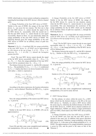
Figure 2. Outage probability of MTC devices vs. SNR. (a) the near MTC
device in the three MTC device pairing schemes; (b) the far MTC device in
RNRF; (c) the far MTC device in NNNF; (d) the far MTC device in NNFF.
special explanation. β2
i1 = 0.25 and β2
i2 = 0.75 are power
allocations for the near MTC device and the far MTC device,
respectively [34], [40]. The other parameters are set as R1 = 4
bits per channel use (BPCU) and R2 = 1.5 BPCU. In addition,
we focus on LOS path in this paper.
Fig. 2 plots the outage probability versus SNR. Each
subfigure in Fig. 2 includes Monte Carlo simulation results,
analytical results and the analytical approximation of outage
probability in RNRF, NNNF and NNFF. The outage probabil-
ity of the near MTC device in NNNF is the same as that of
NNFF, which is simplified as NNN(F)F, as shown in Fig. 2
(a). In this figure, the outage probabilities of the near MTC
device in the three MTC device pairing schemes are given.
Outage probabilities of the far MTC device in RNRF, NNNF
and NNFF are presented in Fig. 2 (b), Fig. 2 (c) and Fig. 2 (d),
respectively. From these subfigures, the following observations
can be made: i) analytical results of RNRF, NNNF and NNFF
match the simulation results well; ii) in the high SNR region,
the analytical approximations are very tight; iii) the near MTC
device in NNN(F)F achieves a lower outage probability as
compared to RNRF.
Fig. 3 plots the outage probability of the near MTC device
versus SNR. The outage probability of the near MTC device
versus SNR is given for different values of the path loss
exponents of RNRF and NNN(F)F, namely α = 2 and α = 3,
respectively. From Fig. 3, several observations are obtained
as follows: i) the outage probability of the near MTC device
in cellular M2M communications with the mmWave-NOMA
transmission scheme is better than that with the mmWave-
OMA transmission scheme; ii) the outage probability of the
near MTC device increases as the path loss exponent increases;
iii) among the three schemes, NNN(F)F achieves the lower
outage probability; iv) if the outage probability of RNRF is](https://image.slidesharecdn.com/lv2018-190814055207/85/Lv2018-8-320.jpg)
![2327-4662 (c) 2018 IEEE. Personal use is permitted, but republication/redistribution requires IEEE permission. See http://www.ieee.org/publications_standards/publications/rights/index.html for more information.
This article has been accepted for publication in a future issue of this journal, but has not been fully edited. Content may change prior to final publication. Citation information: DOI 10.1109/JIOT.2018.2819645, IEEE
Internet of Things Journal
10
0.1 0.15 0.2 0.25 0.3
∆
0.01
0.02
0.03
0.04
0.05
0.06
Outageprobability(N)
RNRF NOMA simulation
RNRF NOMA analysis (17)
NNN(F)F NOMA simulation
NNN(F)F NOMA analysis (29)
(a)
0.1 0.15 0.2 0.25 0.3
∆
0.25
0.3
0.35
0.4
0.45
0.5
0.55
Outageprobability(F)
RNRF NOMA simulation
RNRF NOMA analysis (24)
NNNF NOMA simulation
NNNF NOMA analysis (33)
NNFF NOMA simulation
NNFF NOMA analysis (37)
(b)
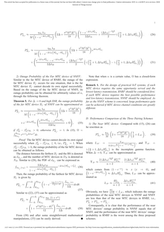
Figure 6. The outage probability vs. ∆. (a) the near MTC device in the
three MTC device pairing schemes. (b) the far MTC device in the three MTC
device pairing schemes.
1 1.5 2 2.5 3 3.5 4 4.5 5 5.5 6
Density of the Near MTC Devices
0.2
0.3
0.4
0.5
0.6
0.7
0.8
0.9
1
OutageProbabilityoftheNearMTCDevices
RNRF NOMA
NNN(F)F NOMA
R
D
A
= 8m
R
D
A
= 5m
R
D
A
= 3m
R
D
A
= 2.5m
Figure 7. The outage probability of the near MTC device vs. density of
the near MTC MTC device with different RDA
, where R1 = 2.5 BPCU,
R2 = 1 BPCU, RDC
= 12, and RDB
= 14.
effective channel gain.
Fig. 7 plots the outage probability of the near MTC device
versus density of the near MTC devices with different RDA .
The outage probability of the near MTC device in NNN(F)F
decrease as the density of the near MTC devices λA increases,
because the possibility of scheduling MTC devices with a
higher effective channel gain improves. However, outage prob-
ability of the near MTC device in RNRF is invariant, this is
because that the possibility of scheduling MTC devices with
a higher effective channel gain does not change. Furthermore,
the outage probability of RNRF and NNN(F)F decreases as
RDA decreases, since the path loss of the near MTC devices
becomes smaller with the decreasing radius.
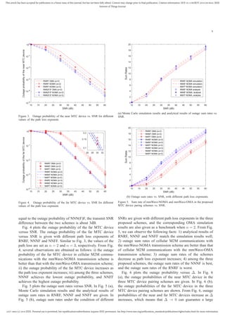
Fig. 8 plots the outage probability of the far MTC device
versus R2 with different RDC and RDB in the three proposed
pairing schemes. The outage probability of the far MTC device
in RNRF, NNNF and NNFF increase as R2 increases, this
is because QoS of MTC devices becomes higher with the
increasing R2. Moreover, outage probabilities of RNRF ,
NNNF and NNFF increase as RDC and RDB increase, since
the path loss of the near MTC devices becomes larger with
the increasing radius.
0.2 0.4 0.6 0.8 1 1.2 1.4 1.6 1.8
R2 (BPCU)
10-3
10-2
10-1
100
OutageProbabilityoftheFarMTCDevices
RNRF NOMA
NNNF NOMA
NNFF NOMA
R
D
C
= 12m, R
D
B
= 14m
R
D
C
= 8m, R
D
B
= 10m
Figure 8. The outage probability of the far MTC device vs. R2 with different
RDC
and RDB
in the three pairing schemes.
V. CONCLUSIONS
In this paper, a new mmWave-NOMA transmission scheme
in cellular M2M communications for IoT which can meet
the QoS offered to MTC devices, has been introduced and
its performance has been analyzed. Based on the distinct
advantages of the proposed mmWave-NOMA transmission
scheme, massive connectivity of IoT can be achieved in
cellular M2M communications. Using the distance between
the MTC device and the BS as a selection criterion, we have
proposed three different MTC device pairing schemes which
can reduce latency and system overhead, and have focused on
a single beam where random beamforming is used. Theoretical
studies have shown that among the proposed three schemes,
the outage probability of the near MTC device of NNN(F)F is
lower than that of the near MTC device of RNRF. Regarding
the outage probability of the far MTC device, NNNF and
NNFF achieve the best and worst performance respectively.
These conclusions have been validated by complementary
performance evaluation results obtained by means of Monte
Carlo computer simulations.
REFERENCES
[1] A. Al-Fuqaha, M. Guizani, M. Mohammadi, M. Aledhari, and
M. Ayyash, “Internet of things: A survey on enabling technologies,
protocols, and applications,” IEEE Commun. Surv. Tuts., vol. 17, no. 4,
pp. 2347–2376, Jun. 2015.
[2] D. Singh, G. Tripathi, and A. J. Jara, “A survey of internet-of-things:
Future vision, architecture, challenges and services,” in Proc. 2014 IEEE
world forum on Internet of things (WF-IoT), Seoul, South Korea, Mar.
2014, pp. 287–292.
[3] A. Zanella, N. Bui, A. Castellani, L. Vangelista, and M. Zorzi, “Internet
of things for smart cities,” IEEE Internet Things J., vol. 1, no. 1, pp.
22–32, Feb. 2014.
[4] J. A. Stankovic, “Research directions for the internet of things,” IEEE
Internet Things J., vol. 1, no. 1, pp. 3–9, Feb. 2014.
[5] S. Li, N. Zhang, S. Lin, L. Kong, A. Katangur, M. K. Khan, M. Ni,
and G. Zhu, “Joint admission control and resource allocation in edge
computing for internet of things,” IEEE Network, vol. 32, no. 1, pp.
72–79, Jan. 2018.
[6] G. Wunder, P. Jung, M. Kasparick, T. Wild, F. Schaich, Y. Chen,
S. Ten Brink, I. Gaspar, N. Michailow, A. Festag et al., “5GNOW: non-
orthogonal, asynchronous waveforms for future mobile applications,”
IEEE Commun. Mag., vol. 52, no. 2, pp. 97–105, Feb. 2014.](https://image.slidesharecdn.com/lv2018-190814055207/85/Lv2018-10-320.jpg)
![2327-4662 (c) 2018 IEEE. Personal use is permitted, but republication/redistribution requires IEEE permission. See http://www.ieee.org/publications_standards/publications/rights/index.html for more information.
This article has been accepted for publication in a future issue of this journal, but has not been fully edited. Content may change prior to final publication. Citation information: DOI 10.1109/JIOT.2018.2819645, IEEE
Internet of Things Journal
11
[7] J. Suomalainen, “Smartphone assisted security pairings for the internet
of things,” in Proc. Wireless Communications, Vehicular Technology,
Information Theory and Aerospace & Electronic Systems (VITAE),
Aalborg, Denmark, May 2014, pp. 1–5.
[8] L. Atzori, A. Iera, and G. Morabito, “The internet of things: A survey,”
Computer networks, vol. 54, no. 15, pp. 2787–2805, May 2010.
[9] X. Liu and N. Ansari, “Green relay assisted D2D communications with
dual battery for IoT,” in Proc. IEEE Global Communications Conference
(GLOBECOM), Washington, DC, Dec. 2016, pp. 1–6.
[10] S. Lin, L. Kong, Q. Gao, M. K. Khan, Z. Zhong, X. Jin, and P. Zeng,
“Advanced dynamic channel access strategy in spectrum sharing 5G
systems,” IEEE Wireless Commun., vol. 24, no. 5, pp. 1536–1284, Oct.
2017.
[11] Y. Liu, Z. Qin, M. Elkashlan, Y. Gao, and L. Hanzo, “Enhancing the
physical layer security of non-orthogonal multiple access in large-scale
networks,” IEEE Trans. Wireless Commun., vol. 16, no. 3, pp. 1656–
1672, Mar. 2017.
[12] Z. Yang, W. Xu, Y. Pan, C. Pan, and M. Chen, “Energy efficient resource
allocation in machine-to-machine communications with multiple access
and energy harvesting for IoT,” IEEE Internet Things J., vol. 5, no. 1,
pp. 229–245, Feb. 2018.
[13] M. Shirvanimoghaddam, M. Dohler, and S. Johnson, “Massive non-
orthogonal multiple access for cellular IoT: Potentials and limitations,”
IEEE Commun. Mag., vol. 55, no. 9, pp. 55–61, Sep. 2017.
[14] S.-Y. Lien, K.-C. Chen, and Y. Lin, “Toward ubiquitous massive accesses
in 3GPP machine-to-machine communications,” IEEE Commun. Mag.,
vol. 49, no. 4, pp. 66–74, Apr. 2011.
[15] M. Shirvanimoghaddam, M. Condoluci, M. Dohler, and S. Johnson, “On
the fundamental limits of random non-orthogonal multiple access in
cellular massive IoT,” IEEE J. Sel. Areas Commun., vol. 35, no. 10, pp.
2238–2252, Oct. 2017.
[16] K. Higuchi and A. Benjebbour, “Non-orthogonal multiple access
(NOMA) with successive interference cancellation for future radio
access,” IEICE Trans. Commun., vol. 98, no. 3, pp. 403–414, Mar. 2015.
[17] K. Higuchi and Y. Kishiyama, “Non-orthogonal access with random
beamforming and intra-beam SIC for cellular MIMO downlink,” in Proc.
IEEE Vehicular Technology Conference (VTC Fall), Las Vegas, NV, Sep.
2013, pp. 1–5.
[18] Z. Ding, L. Dai, R. Schober, and H. V. Poor, “NOMA meets finite
resolution analog beamforming in massive MIMO and millimeter-wave
networks,” IEEE Commun. Lett., vol. 21, no. 8, pp. 1879–1882, Aug.
2017.
[19] Y. Liu, Z. Qin, M. Elkashlan, Z. Ding, A. Nallanathan, and L. Hanzo,
“Nonorthogonal multiple access for 5G and beyond,” Proceedings of the
IEEE, vol. 105, no. 12, pp. 2347–2381, Dec. 2017.
[20] M. F. Kader, M. B. Shahab, and S. Y. Shin, “Exploiting non-orthogonal
multiple access in cooperative relay sharing,” IEEE Commun. Lett.,
vol. 21, no. 5, pp. 1159–1162, May 2017.
[21] S. Timotheou and I. Krikidis, “Fairness for non-orthogonal multiple
access in 5G systems,” IEEE Signal Process. Lett., vol. 22, no. 10, pp.
1647–1651, Oct. 2015.
[22] Y. Liu, M. Elkashlan, Z. Ding, and G. K. Karagiannidis, “Fairness of
user clustering in mimo non-orthogonal multiple access systems,” IEEE
Commun. Lett., vol. 20, no. 7, pp. 1465–1468, Jul. 2016.
[23] S. M. R. Islam, N. Avazov, O. A. Dobre, and K. s. Kwak, “Power-domain
non-orthogonal multiple access (NOMA) in 5G systems: Potentials and
challenges,” IEEE Commun. Surv. Tuts., vol. 19, no. 2, pp. 721–742,
Oct. 2017.
[24] Z. Ding, F. Adachi, and H. V. Poor, “The application of MIMO to non-
orthogonal multiple access,” IEEE Trans. Wireless Commun., vol. 15,
no. 1, pp. 537–552, Jan. 2016.
[25] Y. Liu, Z. Qin, M. Elkashlan, A. Nallanathan, and J. A. McCann, “Non-
orthogonal multiple access in large-scale heterogeneous networks,” IEEE
J. Sel. Areas Commun., vol. 35, no. 12, pp. 2667 – 2680, Dec. 2017.
[26] Z. Ding, X. Lei, G. K. Karagiannidis, R. Schober, J. Yuan, and V. K.
Bhargava, “A survey on non-orthogonal multiple access for 5G networks:
Research challenges and future trends,” IEEE J. Sel. Areas Commun.,
vol. 35, no. 10, pp. 2181–2198, Oct. 2017.
[27] Z. Ding, P. Fan, and V. Poor, “Impact of user pairing on 5G non-
orthogonal multiple access downlink transmissions,” IEEE Trans. Veh.
Technol., vol. 65, no. 8, pp. 6010–6023, Aug. 2016.
[28] B. Kimy, S. Lim, H. Kim, S. Suh, J. Kwun, S. Choi, C. Lee, S. Lee,
and D. Hong, “Non-orthogonal multiple access in a downlink multiuser
beamforming system,” in Proc. IEEE Military Communications Confer-
ence (MILCOM), San Diego, CA, Nov. 2013, pp. 1278–1283.
[29] S. Liu, C. Zhang, and G. Lyu, “User selection and power schedule for
downlink non-orthogonal multiple access (NOMA) system,” in Proc.
IEEE International Conference on Communication Workshop (ICCW),
London, UK, Jun. 2015, pp. 2561–2565.
[30] B. Kim, W. Chung, S. Lim, S. Suh, J. Kwun, S. Choi, and D. Hong,
“Uplink NOMA with multi-antenna,” in Proc. IEEE Vehicular Technol-
ogy Conference (VTC Spring), Glasgow, UK, May 2015, pp. 1–5.
[31] J. Kim, J. Koh, J. Kang, K. Lee, and J. Kang, “Design of user clustering
and precoding for downlink non-orthogonal multiple access (NOMA),”
in Proc. IEEE Military Communications Conference (MILCOM), Tampa,
FL, Oct. 2015, pp. 1170–1175.
[32] Z. Zhang, Z. Ma, Y. Xiao, M. Xiao, G. K. Karagiannidis, and P. Fan,
“Non-orthogonal multiple access for cooperative multicast millimeter
wave wireless networks,” IEEE J. Sel. Areas Commun., vol. 35, no. 8,
pp. 1794–1808, Aug. 2017.
[33] A. S. Marcano and H. L. Christiansen, “Performance of non-orthogonal
multiple access (NOMA) in mmwave wireless communications for
5G networks,” in Proc. Computing, Networking and Communications
(ICNC), Santa Clara, CA, Jan. 2017, pp. 969–974.
[34] Z. Ding, P. Fan, and H. V. Poor, “Random beamforming in millimeter-
wave NOMA networks,” IEEE Access, vol. 5, pp. 7667–7681, Feb. 2017.
[35] L. Kong, M. K. Khan, F. Wu, G. Chen, and P. Zeng, “Millimeter-wave
wireless communications for IoT-cloud supported autonomous vehicles:
Overview, design, and challenges,” IEEE Commun. Mag., vol. 55, no. 1,
pp. 62–68, Jan. 2017.
[36] Z. Ding, L. Dai, and H. V. Poor, “MIMO-NOMA design for small packet
transmission in the internet of things,” IEEE Access, vol. 4, pp. 1393–
1405, Apr. 2016.
[37] H. Sun, Q. Wang, S. Ahmed, and R. Q. Hu, “Non-orthogonal multiple
access in a mmWave based IoT wireless system with SWIPT,” in
Proc. Vehicular Technology Conference (VTC Spring), Sydney, NSW,
Australia, Jun. 2017, pp. 1–5.
[38] Z. Yang, W. Xu, H. Xu, J. Shi, and M. Chen, “Energy efficient non-
orthogonal multiple access for machine-to-machine communications,”
IEEE Commun. Lett., vol. 21, no. 4, pp. 817–820, Apr. 2017.
[39] G. Lee, Y. Sung, and J. Seo, “Randomly-directional beamforming
in millimeter-wave multiuser MISO downlink,” IEEE Trans. Wireless
Commun., vol. 15, no. 2, pp. 1086–1100, Feb. 2016.
[40] Y. Liu, Z. Ding, M. Elkashlan, and H. V. Poor, “Cooperative non-
orthogonal multiple access with simultaneous wireless information and
power transfer,” IEEE J. Sel. Areas Commun., vol. 34, no. 4, pp. 938–
953, Apr. 2016.
Tiejun Lv (M’08-SM’12) received the M.S. and
Ph.D. degrees in electronic engineering from the
University of Electronic Science and Technology of
China (UESTC), Chengdu, China, in 1997 and 2000,
respectively. From January 2001 to January 2003, he
was a Postdoctoral Fellow with Tsinghua University,
Beijing, China. In 2005, he was promoted to a Full
Professor with the School of Information and Com-
munication Engineering, Beijing University of Posts
and Telecommunications (BUPT). From September
2008 to March 2009, he was a Visiting Professor
with the Department of Electrical Engineering, Stanford University, Stanford,
CA, USA. He is the author of more than 50 published IEEE journal papers and
170 conference papers on the physical layer of wireless mobile communica-
tions. His current research interests include signal processing, communications
theory and networking. He was the recipient of the Program for New Century
Excellent Talents in University Award from the Ministry of Education, China,
in 2006. He received the Nature Science Award in the Ministry of Education of
China for the hierarchical cooperative communication theory and technologies
in 2015.](https://image.slidesharecdn.com/lv2018-190814055207/85/Lv2018-11-320.jpg)