This document discusses the importance of millimeter-wave technologies in the development of 5G and future 6G wireless communications. It highlights the advancements in system architectures, beamforming technologies, antennas, and the need to meet the requirements of new data-driven applications. The paper reviews current state-of-the-art technologies and outlines challenges and directions for future research in this field.
![Received 28 August 2020; revised 20 October 2020 and 25 October 2020; accepted 26 October 2020.
Date of current version 7 January 2021.
Digital Object Identifier 10.1109/JMW.2020.3035541
The Role of Millimeter-Wave Technologies in
5G/6G Wireless Communications
WEI HONG 1,2 (Fellow, IEEE), ZHI HAO JIANG 1,2 (Member, IEEE), CHAO YU 1,2 (Member, IEEE),
DEBIN HOU 1, HAIMING WANG 1,2 (Member, IEEE), CHONG GUO1 (Graduate Student Member, IEEE),
YUN HU2 (Member, IEEE), LE KUAI 1, YINGRUI YU 1 (Member, IEEE), ZHENGBO JIANG 1 (Member, IEEE),
ZHE CHEN 1 (Member, IEEE), JIXIN CHEN 1,2 (Member, IEEE), ZHIQIANG YU 1,2 (Member, IEEE),
JIANFENG ZHAI 1,2 (Member, IEEE), NIANZU ZHANG1, LING TIAN1,2 (Member, IEEE),
FAN WU 1 (Member, IEEE), GUANGQI YANG1,2, ZHANG-CHENG HAO 1,2 (Senior Member, IEEE),
AND JIAN YI ZHOU 1,2 (Member, IEEE)
(Invited Paper)
1
State Key Laboratory of Millimeter-Waves, School of Information Science and Engineering, Southeast University, Nanjing 210096, China
2
Purple Mountain Laboratories, Nanjing 211111, China
CORRESPONDING AUTHORS: WEI HONG; ZHI HAO JIANG (e-mail: weihong@seu.edu.cn; zhihao.jiang@seu.edu.cn).
This work was supported in part by the National Key Research and Development Program of China under Grant 2020YFB1804900, in part by the National Natural
Science Foundation of China (NSFC) under Grant 61627801, and in part by the High Level Innovation and Entrepreneurial Research Team Program in Jiangsu.
ABSTRACT Ever since the deployment of the first-generation of mobile telecommunications, wireless
communication technology has evolved at a dramatically fast pace over the past four decades. The upcoming
fifth-generation (5G) holds a great promise in providing an ultra-fast data rate, a very low latency, and a
significantly improved spectral efficiency by exploiting the millimeter-wave spectrum for the first time in
mobile communication infrastructures. In the years beyond 2030, newly emerged data-hungry applications
and the greatly expanded wireless network will call for the sixth-generation (6G) communication that
represents a significant upgrade from the 5G network – covering almost the entire surface of the earth
and the near outer space. In both the 5G and future 6G networks, millimeter-wave technologies will play
an important role in accomplishing the envisioned network performance and communication tasks. In this
paper, the relevant millimeter-wave enabling technologies are reviewed: they include the recent developments
on the system architectures of active beamforming arrays, beamforming integrated circuits, antennas for
base stations and user terminals, system measurement and calibration, and channel characterization. The
requirements of each part for future 6G communications are also briefly discussed.
INDEX TERMS 5G communications, 6G communications, antennas, beamforming, calibration, digital ar-
rays, phased arrays, RF integrated circuits, measurement, multibeam arrays, propagation channels, wireless
systems.
I. INTRODUCTION
More than a century ago, in the 1890s, the capability of using
electromagnetic waves to transmit signals wirelessly was
demonstrated, for the first time, in the famous wireless telegra-
phy experiment conducted by Nobel Laureate G. Marconi [1].
It took around 80 years to turn it into commercial applications
with which people can connect each other in real-time. Ever
since then, the technologies of mobile communications have
evolved rapidly due to the developments in communication
theory and multiplexing methods, microelectronics and
integrated circuits (ICs), microwave circuits and antennas,
and so on [2], [3]. Beginning from the 1980s, a new generation
has emerged almost every decade [4]. The first-generation
(1G) of mobile communications was based on analog
communications by using the frequency-division multiplexing
access (FDMA). It only allowed voice signal transfer
This work is licensed under a Creative Commons Attribution 4.0 License. For more information, see https://creativecommons.org/licenses/by/4.0/
VOLUME 1, NO. 1, JANUARY 2021 101](https://image.slidesharecdn.com/theroleofmillimeter-wavetechnologiesin5g6gwirelesscommunications-240922201956-627b2cbc/85/The_Role_of_Millimeter-Wave_Technologies_in_5G_6G_Wireless_Communications-pdf-1-320.jpg)
![Received 28 August 2020; revised 20 October 2020 and 25 October 2020; accepted 26 October 2020.
Date of current version 7 January 2021.
Digital Object Identifier 10.1109/JMW.2020.3035541
The Role of Millimeter-Wave Technologies in
5G/6G Wireless Communications
WEI HONG 1,2 (Fellow, IEEE), ZHI HAO JIANG 1,2 (Member, IEEE), CHAO YU 1,2 (Member, IEEE),
DEBIN HOU 1, HAIMING WANG 1,2 (Member, IEEE), CHONG GUO1 (Graduate Student Member, IEEE),
YUN HU2 (Member, IEEE), LE KUAI 1, YINGRUI YU 1 (Member, IEEE), ZHENGBO JIANG 1 (Member, IEEE),
ZHE CHEN 1 (Member, IEEE), JIXIN CHEN 1,2 (Member, IEEE), ZHIQIANG YU 1,2 (Member, IEEE),
JIANFENG ZHAI 1,2 (Member, IEEE), NIANZU ZHANG1, LING TIAN1,2 (Member, IEEE),
FAN WU 1 (Member, IEEE), GUANGQI YANG1,2, ZHANG-CHENG HAO 1,2 (Senior Member, IEEE),
AND JIAN YI ZHOU 1,2 (Member, IEEE)
(Invited Paper)
1
State Key Laboratory of Millimeter-Waves, School of Information Science and Engineering, Southeast University, Nanjing 210096, China
2
Purple Mountain Laboratories, Nanjing 211111, China
CORRESPONDING AUTHORS: WEI HONG; ZHI HAO JIANG (e-mail: weihong@seu.edu.cn; zhihao.jiang@seu.edu.cn).
This work was supported in part by the National Key Research and Development Program of China under Grant 2020YFB1804900, in part by the National Natural
Science Foundation of China (NSFC) under Grant 61627801, and in part by the High Level Innovation and Entrepreneurial Research Team Program in Jiangsu.
ABSTRACT Ever since the deployment of the first-generation of mobile telecommunications, wireless
communication technology has evolved at a dramatically fast pace over the past four decades. The upcoming
fifth-generation (5G) holds a great promise in providing an ultra-fast data rate, a very low latency, and a
significantly improved spectral efficiency by exploiting the millimeter-wave spectrum for the first time in
mobile communication infrastructures. In the years beyond 2030, newly emerged data-hungry applications
and the greatly expanded wireless network will call for the sixth-generation (6G) communication that
represents a significant upgrade from the 5G network – covering almost the entire surface of the earth
and the near outer space. In both the 5G and future 6G networks, millimeter-wave technologies will play
an important role in accomplishing the envisioned network performance and communication tasks. In this
paper, the relevant millimeter-wave enabling technologies are reviewed: they include the recent developments
on the system architectures of active beamforming arrays, beamforming integrated circuits, antennas for
base stations and user terminals, system measurement and calibration, and channel characterization. The
requirements of each part for future 6G communications are also briefly discussed.
INDEX TERMS 5G communications, 6G communications, antennas, beamforming, calibration, digital ar-
rays, phased arrays, RF integrated circuits, measurement, multibeam arrays, propagation channels, wireless
systems.
I. INTRODUCTION
More than a century ago, in the 1890s, the capability of using
electromagnetic waves to transmit signals wirelessly was
demonstrated, for the first time, in the famous wireless telegra-
phy experiment conducted by Nobel Laureate G. Marconi [1].
It took around 80 years to turn it into commercial applications
with which people can connect each other in real-time. Ever
since then, the technologies of mobile communications have
evolved rapidly due to the developments in communication
theory and multiplexing methods, microelectronics and
integrated circuits (ICs), microwave circuits and antennas,
and so on [2], [3]. Beginning from the 1980s, a new generation
has emerged almost every decade [4]. The first-generation
(1G) of mobile communications was based on analog
communications by using the frequency-division multiplexing
access (FDMA). It only allowed voice signal transfer
This work is licensed under a Creative Commons Attribution 4.0 License. For more information, see https://creativecommons.org/licenses/by/4.0/
VOLUME 1, NO. 1, JANUARY 2021 101](https://image.slidesharecdn.com/theroleofmillimeter-wavetechnologiesin5g6gwirelesscommunications-240922201956-627b2cbc/75/The_Role_of_Millimeter-Wave_Technologies_in_5G_6G_Wireless_Communications-pdf-1-2048.jpg)
![HONG ET AL.: ROLE OF MILLIMETER-WAVE TECHNOLOGIES IN 5G/6G WIRELESS COMMUNICATIONS
with limited and unstable spatial coverage [5]. The
second-generation (2G) uses digital communications
where the time-division multiplexing access (TDMA) and
code-division multiplexing access (CDMA) were adopted.
The 2G ensured a more stable link, a much wider coverage,
and supported text messaging among users [6], [7]. The
third-generation (3G) employs variations of advanced CDMA
techniques and supports more versatile services, including,
for the first time, multimedia data transfer [7], [8]. With the
help of orthogonal frequency-division multiplexing (OFDM)
and multiple-input multiple-output (MIMO) techniques,
the fourth-generation (4G), including the 3.9G long term
evolution (LTE) and 4G LTE-advanced was developed.
They are able to offer a dramatically faster speed than 3G,
providing a data rate of tens of megabytes per second [9],
[10]. The revolutionary icon of the 4G era was the burgeoning
widespread usage of smart-phones across the world, which
changed the life style of human beings and the way people
connect with each other. In terms of the frequency spectrums
that are designated for the different generations of mobile
communications, we can make two observations. First, more
frequency bands have been gradually released for a larger
channel bandwidth that can meet the demands for higher data
rates [5]. Secondly, all the released frequency bands are below
4 GHz, primarily due to two facts: 1) the electromagnetic
waves below 4 GHz are less susceptible to blockage and
weather changes and 2) the hardware chips and components
are more cost-friendly and power-efficient.
With the fast growing of the number of consumer wireless
devices in use and the expansion of the Internet of Things
(IoT), the amount of mobile data transfer is almost dou-
bled every year, surpassing that of the wired communications
[14]. The 4G mobile network infrastructure can no longer
meet the needs for high-speed wireless data transmission.
Therefore, from the second decade of the 21st century, the
fifth-generation (5G) of mobile communications emerges with
the outlook to the sixth-generation (6G) [11]–[13]. The 5G
has been deployed in 2019 and is on the corner of mas-
sive commercialization. The international telecommunication
union (ITU) has defined three major application scenarios for
5G new radio (NR): they are the enhanced mobile broadband
(eMBB), massive machine type communication (mMTC),
and ultra-reliable low latency communication (URLLC) [see
Fig. 1]. The 5G is expected to support a data rate of a few
gigabits per second (Gb/s), a latency of milli-second, and a
high volume of traffic density with greatly improved spectral,
energy, and cost efficiencies [15]. In order to meet these re-
quirements, a number of enabling network and hardware tech-
nologies have been developed, including ultra-dense network-
ing, all-spectrum access, massive MIMO, and full-duplexing
[16], [17].
Importantly, from the frequency resource point-of-view, the
uniqueness of 5G, in comparison with 3G and 4G, is the uti-
lization of millimeter-wave (mmWave) frequencies in mobile
communications, mainly due to two reasons [18], [19]. First,
the sub-6 GHz spectrum has already been very crowded, filled
FIGURE 1. Conceptual illustration of the 6G communication network that
encompasses the 5G network.
FIGURE 2. The mmWave 5G bands released by different countries.
with distributed bands dedicated for cellular communications,
satellite and aerial communications, and wireless local area
networks (WLANs). On the contrary, at mmWave frequencies
from 6 GHz up to 300 GHz, there are many unlicensed bands
– the available spectrum is abundant. Secondly, the absolute
bandwidth at mmWave frequencies is much larger than that
at the lower microwave frequencies under the same relative
bandwidth. The Third Generation Partnership Project (3GPP)
has divided the 5G New Radio (NR) into FR1 band, i.e., 410
– 7125 MHz, and FR2 band, or also called mmWave band,
i.e., 24.25 – 52.6 GHz [20]. In addition to the narrow bands
around 3.5 GHz and 4.9 GHz, many countries have released
a number of mmWave bands for 5G NR communications
in the Ka-band, Q-band, and even E-band [see Fig. 2] [22].
Consequently, the system architecture, transceiver channels,
ICs, passive and active components, and propagation channel
modeling have become the main cutting edges of research
[23]–[26].
102 VOLUME 1, NO. 1, JANUARY 2021](https://image.slidesharecdn.com/theroleofmillimeter-wavetechnologiesin5g6gwirelesscommunications-240922201956-627b2cbc/85/The_Role_of_Millimeter-Wave_Technologies_in_5G_6G_Wireless_Communications-pdf-2-320.jpg)
![Moving towards 2030 and beyond, due to the fast growth of
new technologies such as virtual reality, vehicle-to-X network,
unmanned aerial vehicle network, mid-earth-orbit (MEO) and
low-earth-orbit (LEO) satellite network, and oceanic informa-
tion network, the 5G communications would become insuf-
ficient. Therefore, very recently, several countries have called
for or initiated research programs for the sixth generation (6G)
of mobile communications. Although the specs of 6G, such
as frequency bands, data rate requirements, have not been
defined and finalized, its applications have been considered. A
consensus for 6G has been reached – the 6G will be an intelli-
gent mobile communication network of a much larger scale
that encompasses the 5G [13], [27]. While the quasi-two-
dimensional 5G network only covers a limited portion of lands
on earth, the 6G network will extend into three dimensions
and connects the satellites, aircraft, ships, and land-based in-
frastructures, providing a truly global coverage. The mmWave
technologies will play an important role in enabling the vari-
ous wireless links with enhanced speed and reliability superior
to 5G. In addition, the use of terahertz has also been proposed
as a part of the frequency bands for 6G communications [27].
However, the related key devices of terahertz chips, front-end
components, and systems are not yet as mature and reliable
as those operating at mmWave frequencies for long-distance
communications with a high fidelity.
In this paper, the mmWave technologies that are important
to 5G communications are reviewed, including the massive
MIMO system architectures, beamforming chips, antennas for
base stations (BSs) and user terminals (UTs), system measure-
ment and calibration techniques, and wireless channel charac-
terization. Then, the challenges and requirements for future
6G communications are discussed. The paper is organized as
follows. Section II illustrates the system architectures of active
multibeam arrays, including a comparison among different
beamforming strategies. In Section III, the mmWave chips for
beamforming are presented. The mmWave antennas for both
BSs and UTs are described in Section IV, along with a discus-
sion on several advanced antenna technologies. In Section V,
the methods for system calibration and pattern measurement,
RF testing, and system performance testing are reported. Sec-
tion VI presents a brief overview of channel characterization,
followed by conclusions drawn in Section VII.
II. mmWAVE SYSTEMS FOR 5G/6G COMMUNICATIONS
To overcome the large free-space path loss of the radiated
waves at mmWave frequencies, beamforming techniques have
been widely employed in 5G wireless systems for effectively
focusing the radiated energy into the targeted directions. As
shown in Fig. 3, the general architecture for a 5G mmWave
BS is illustrated, including the active antenna units (AAUs),
the baseband units (BBUs), and the core network (CN). The
beamforming AAU contains an antenna array, down/up con-
verters, analog-to-digital converters (ADCs), digital-to-analog
converters (DAC), beam management units, and AAU base-
band signal processing units. To realize the desirable beam-
forming functions, proper amplitude and phase should be
FIGURE 3. An illustration of the system architecture of a 5G base station.
assigned to each antenna element. In this section, several
mainstream beamforming architectures will be described and
compared, followed by a discussion on potential system archi-
tectures for 6G systems.
A. SYSTEM ARCHITECTURE
Based on the methods to phase each antenna element, we
can divide beamforming architectures for 5G wireless systems
into three types: analog beamforming [28]–[37], full-digital
beamforming [38]–[40], and hybrid beamforming [41]–[46]
[see Fig. 4].
Due to its low-cost and implementation convenience, the
analog beamforming has been widely employed, in which
phase shifting is realized in the analog domain, as shown
in Fig. 2(a). Depending on the location of the analog phase
shifting performed in the system, it can be categorized into
intermediate frequency phase shifting [31], local oscillator
(LO) phase shifting [28], and radio frequency (RF) phase
shifting [32], [33]. The phase-shifting can be realized by uti-
lizing digitally-controlled phase shifters, such as a 6-bit phase
shifter, or static analog beamforming structures, such as the
Butler matrices [34], Blass matrices [35], and lenses [36]. It
is worth mentioning that the phase shifter is one of the most
popular schemes in commercial beamforming chips, in which
the digital control of phase shifting can be pre-calibrated and
stored in the memory for fast and precise beam generation.
For example, a Ka-band phased array antenna with 64 radiat-
ing elements based on quad-core monolithic microwave ICs
(MMICs) has been demonstrated, as shown in Fig. 5 [37].
Compared with the analog beamforming, the full-digital
beamforming possesses more flexibility. As shown in
Fig. 4(b), each antenna is directly connected to a transceiver
chain, followed by an ADC/DAC with a high sampling rate
and precision. A Q-band 64-channel full-digital beamforming
transceiver for 5G communications has been proposed and
implemented [40], covering a frequency range from 37 to
42.5 GHz [see Fig. 6]. Due to the employed digital circuit,
this kind of beamforming structure can realize a high beam-
forming performance, especially for multi-beam radiation and
reception. However, the cost of hardware implementation and
VOLUME 1, NO. 1, JANUARY 2021 103](https://image.slidesharecdn.com/theroleofmillimeter-wavetechnologiesin5g6gwirelesscommunications-240922201956-627b2cbc/85/The_Role_of_Millimeter-Wave_Technologies_in_5G_6G_Wireless_Communications-pdf-3-320.jpg)
![HONG ET AL.: ROLE OF MILLIMETER-WAVE TECHNOLOGIES IN 5G/6G WIRELESS COMMUNICATIONS
FIGURE 4. Illustrations of the different beamforming system architectures:
(a) analog beamforming, (b) full-digital beamforming, and (c) hybrid
beamforming.
FIGURE 5. Photographs of a Ka-band analog beamforming array module
based on phase shifting chips (reproduced from [37]).
FIGURE 6. Photographs of Q-band digital beamforming array modules
[40].
FIGURE 7. Photographs of a prototype of the hybrid beamforming array
(reproduced from [44]).
the burden of signal processing in the baseband will increase
very quickly as the channel number increases or the channel
bandwidth broadens, limiting its commercialization.
To realize the trade-off between system performance and
hardware complexity, the hybrid beamforming structure was
proposed and has been widely applied in the development
of commercial active antenna units (AAUs), as shown in
Fig. 4(c). In [44], the authors presented a hybrid beamformer
consisting of two RF channels connecting to the baseband and
a 128-element antenna array [see Fig. 7]. In such a structure,
the phase distribution is realized in both the digital and analog
domains, leading to a significant reduction in the number of
RF chains.
Currently, the 5G wireless communication systems mainly
adopts the hybrid beamforming scheme. Depending on the
application scenarios, the BSs [47] and UTs [48] usually have
different requirements. For the BSs, massive MIMO can be
deployed to obtain satisfactory equivalent isotropically radi-
ated power (EIRP), in which the circuit architectures should
be designed by considering the power level. For example,
for a medium EIRP, the multi-channel beamforming ICs with
antenna-in-package (AIP) technologies [49] can be used for
achieving a high level of integration. However, for large EIRP
requirements, additional power amplifiers with advanced pro-
cessing technology can be employed, such as GaN [50]. For
the UT, to achieve high-density integration and low power
consumption, AIP or antenna-in-module (AIM) [51] tech-
nologies are preferable. Besides, to obtain a broad spatial
coverage, many AIPs or AIMs are required to be integrated
together. In general, such hybrid beamforming structures can
have a satisfactory performance with relatively lower com-
plexity, enabling large scale deployment. It is worth noting
104 VOLUME 1, NO. 1, JANUARY 2021](https://image.slidesharecdn.com/theroleofmillimeter-wavetechnologiesin5g6gwirelesscommunications-240922201956-627b2cbc/85/The_Role_of_Millimeter-Wave_Technologies_in_5G_6G_Wireless_Communications-pdf-4-320.jpg)
![that, in the current mobile communication market, a radio
system is usually supplied by a single company, making it
difficult to interface with the systems or components provided
by any other third party. To address this issue, the concept of
the open radio access network (O-RAN) has been proposed
recently [52]. It allows for open interfaces for 5G equipment,
aiming at establishing a healthier eco-system for 5G commu-
nications.
B. POTENTIAL SYSTEM ARCHITECTURE FOR 6G
COMMUNICATIONS
To further extend the capability of communication systems,
the concept of 6G has recently emerged [13]. The purpose of
from 1G to 5G is to build wireless connections among people,
mainly in the terrestrial land areas or environments. However,
most of the areas on the earth are oceans, deserts, and the near
outer space. The 6G is intended to cover these areas and sup-
port an integrated ground-air-space network [53], covering the
entire earth’s surface and near outer space. Several pioneered
companies have initiated projects for enabling networks of
such kind, including SpaceX [54], Amazon, and OneWeb
[55].
To meet the demands for 6G communications, future wire-
less systems need to be reconfigurable [56] and intelligent
[57]. The reconfigurability should include system hardware
re-uses and mode-switching. Meanwhile, with the rapid de-
velopment of artificial intelligence [57], [58], such as machine
learning [59], a 6G system is also required to be intelligent for
providing better services, including the adaptation to environ-
ments and changes of functionality.
C. SYSTEM REQUIREMENTS FOR ASYMMETRICAL
WIRELESS SYSTEM
Conventionally, the transmitter and receiver antenna arrays are
reciprocal. However, from the system point of view, this is not
necessary since the transmitter and receiver could have differ-
ent requirements and functionality, depending on the specific
application scenarios. Therefore, asymmetric architecture is
an alternative option for future designs, resulting in a better
efficiency and lower cost and complexity.
In order to incorporate the asymmetric property into a full-
digital array, a novel transmitting and receiving beamforming
strategy was proposed recently [60], in which nonrecipro-
cal beamforming was developed. It achieves the asymmet-
rical transmitting and receiving beam patterns, as shown in
Fig. 8(a). The general goal of such a structure is to reduce
both the hardware and baseband resource consumption while
keeping the salient properties of the full-digital arrays. As a
proof-of-concept validation on the proposed system structure,
an asymmetrical full-digital array prototype was developed as
shown in Fig. 8(b). It can be seen that the Tx array employs
16 × 16 full-digital channels surrounded by dummy elements,
while the Rx array only contains two sets of 1 × 16 full-digital
channels. Compared with the conventional arrays having the
same number of transmitting and receiving channels, this
leads to a significant reduction in hardware resources, power
FIGURE 8. (a) System architecture and (b) a prototype photograph of the
asymmetric beamforming arrays.
consumption, and signal processing. For such a system, the
transmitting and receiving beams can still possess a broad
coverage with a high degree of beamforming flexibility.
To appreciate the advantages of the proposed architecture, a
performance comparison among different beamforming array
structures is listed in Table 1. The asymmetrical full-digital
array has properties similar to those of a conventional sym-
metrical one, such as broad instantaneous coverage, low com-
plexity, and high system capacity. The complexity and cost of
system implementation, as well as the total power consump-
tion are greatly reduced. In short, asymmetrical full-digital
array poses as one of the most promising candidates for 6G
communication systems. It will present different design re-
quirements and challenges for beamforming ICs, transceiver
channels, and antenna arrays.
III. mmWAVE BEAMFORMING CHIPS FOR 5G/6G
COMMUNICATIONS
Silicon based mmWave chips are one of the main solutions
for current 5G mmWave arrays and are also one of the most
competitive technologies for 6G mmWave arrays. In this
section, typical architectures of mmWave chips for hybrid
massive MIMO and the performance of currently available
commercial TRx beamformer chips are described. In addition,
VOLUME 1, NO. 1, JANUARY 2021 105](https://image.slidesharecdn.com/theroleofmillimeter-wavetechnologiesin5g6gwirelesscommunications-240922201956-627b2cbc/85/The_Role_of_Millimeter-Wave_Technologies_in_5G_6G_Wireless_Communications-pdf-5-320.jpg)
![HONG ET AL.: ROLE OF MILLIMETER-WAVE TECHNOLOGIES IN 5G/6G WIRELESS COMMUNICATIONS
TABLE 1. Comparison Among Different mmWave Beamforming System Architectures
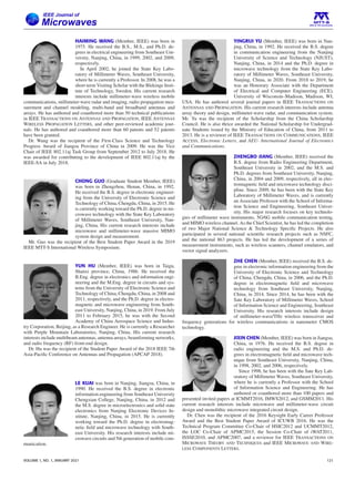
FIGURE 9. (a) Architecture of a 16-element 4-cell 5G hybrid massive
MIMO array module based on 8/4 Tx/Rx beamformer chips. (b) Block
diagram of an 8-channel TRx beamformer chip.
potential chip architectures for asymmetrical massive MIMO
systems are also discussed.
A. mmWAVE CHIPS FOR HYBRID MASSIVE MIMO
A typical hybrid massive MIMO array chipset is shown in
Fig. 9(a), which is composed of 16 antennas, one intermedi-
ate frequency (IF) channel, and one baseband channel. It in-
cludes 8/4 multi-channel beamformer chips and one up/down
converter (UDC) chip that connect to the IF and baseband
channel.
Depending on the type of antenna elements (single- or dual-
polarized), 4-channel or 8-channel TRx beamformer chips
should be used to support a subarray of 2 × 2 elements.
The current 8/4-channel TRx beamformer chip’s function is to
adjust each RF channel’s phase and amplitude. [61] presents
the basic functions of beamformers that have been commer-
cialized in industries. Fig. 9(b) shows a simplified block di-
agram of the 8-channel TRx beamformer chip. A single Tx
chain contains a PA, a digitally-controlled phase shifter, and
an attenuator. A single Rx chain contains a low noise amplifier
(LNA), a digitally-controlled phase shifter, and an attenua-
tor. RF switches are used to switch the operation mode in a
time-division duplex (TDD) based communication system. In
order to combine all the signals from the TRx channels, the
beamformer also contains a power combining/splitting circuit
inside the chip.
Many early works used different manufacturing processes
such as SiGe, CMOS, and SOI, with the channel numbers
ranging from 4 to 32 [47], [62]–[64]. For industrial applica-
tions, most of the chips use SiGe process containing 4 chan-
nels for single-polarized antennas and 8 channels for dual-
polarized antennas. Table 2 lists some commercially available
TRx beamformer chips and their performance parameters are
available in the public domain. Fig. 10 shows a photograph
of a packaged 8-channel TRx beamformer chip using the
WLCSP package from MISIC microelectronics.
The UDC chips are used to interface the baseband cir-
cuits by performing frequency conversion between RF and IF.
Fig. 11 shows the block diagram of a UDC chip. The UDC
chip contains an up converter and a down converter. In the
down converter, the received RF signal will be filtered with
its amplitude controlled. Then the signal will be converted to
IF I/Q signal for baseband processing. In the up converter, the
IF I/Q signal generated at the baseband will be converted to
RF. Then, it will be filtered with its amplitude controlled to
interface with RF beamformer chips.
B. mmWAVE CHIPS FOR ASYMMETRICAL MASSIVE
MIMO SYSTEMS
For asymmetrical massive MIMO systems, since the signal
from each antenna element will be processed in the base-
band, the signal combining/splitting circuit can be eliminated.
Hence, the block diagram of multi-channel mmWave chips
for asymmetric wireless systems is different from that for the
hybrid massive MIMO array systems.
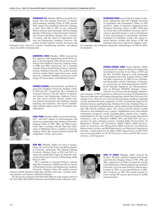
Fig. 12(a) shows the architecture of a Tx array module with
16 antennas elements. The chipsets include four 4-channels
with an up converter for each channel inside the chip. The
number of IF channels is equal to that of the RF channels.
Fig. 12(b) shows an asymmetrical Rx array module containing
8-antenna elements. The chipsets include two 4-channel chips
with down converters inside.
Figs. 13(a) and (b) show the block diagrams of multi-
channel Tx and Rx chips with mixers for asymmetrical
massive MIMO arrays. While the Tx chain contains the typi-
cal transmitter circuits including mixers, filters, PAs, etc., the
106 VOLUME 1, NO. 1, JANUARY 2021](https://image.slidesharecdn.com/theroleofmillimeter-wavetechnologiesin5g6gwirelesscommunications-240922201956-627b2cbc/85/The_Role_of_Millimeter-Wave_Technologies_in_5G_6G_Wireless_Communications-pdf-6-320.jpg)
![HONG ET AL.: ROLE OF MILLIMETER-WAVE TECHNOLOGIES IN 5G/6G WIRELESS COMMUNICATIONS
wireless communication systems [65]. Their electrical prop-
erties, including the input impedance, radiation pattern, gain,
polarization, and passive intermodulation, will affect the sig-
nal coverage, efficiency, noise figure, and linearity of the sys-
tem. For 5G communications, the system requirements call
for new broadband/multiband and fully-integrated mmWave
antennas with dual-polarization and wide beam coverage
[22], [66]. Therefore, extensive efforts have been made on
mmWave antennas for 5G BSs and UTs in academia and in-
dustry. In this section, the recently developed state-of-the-art
mmWave antennas and related advanced technologies will be
discussed.
A. mmWAVE ANTENNAS FOR 5G BSS
For 5G BSs, large antenna arrays with a large number of
elements are required. It can provide a high degree of freedom
for achieving flexible beamforming [67]. In the sub-6 GHz
frequency range, ±45° dipole antennas with vertically as-
sembled balun circuits are commonly used as dual-polarized
radiating elements for BSs [68]. Conventionally, an antenna
is usually designed and fabricated and then connected to the
RF front-end modules using cables. However, such a process
is no longer suitable for massive MIMO arrays at mmWave
frequencies, since phase and amplitude variations caused by
the cables and connectors among a large number of channels
could be significant. For 5G BSs, the antenna array and the
RF front-end circuits need to be fully integrated and jointly
designed [69].
In addition, a wide and stable beamwidth that can be sup-
ported within one or more issued 5G mmWave frequency
bands is much desirable. So far, several types of mmWave an-
tennas for BS applications have been proposed, including the
tapered slot antennas fed by substrate integrated waveguides
(SIWs) [70], magneto electric dipoles [71], vertically-folded
patches [72], metasurface radiators [73], aperture radiators
[74], and so on. However, they do not have dual-polarization,
which limits their applications in 5G BSs.
More advanced dual-polarized antenna elements have also
been proposed, with circular patches [75], cavity-backed
shorted patches [76], and crossed slots [77]. They have the
advantages of being low-profile and low-cost. But their band-
width is only about 10%, which is not wide enough to cover
the 5G bands at Ka-band and Q-band. To further extend the
bandwidth, stacked patches [37], magneto-electric dipoles fed
by SIWs [78], and stacked patches with shorting pins and
parasitic elements [79] were proposed. They can achieve a
matched impedance bandwidth of about 20% with a stable
pattern. Moreover, by exciting multiple characteristic modes
in a metasurface with non-uniform unit cells, dual-band was
realized that simultaneously covers the 5G bands at Ka-band
and Q-band [80]. In addition, antenna elements that support
dual-circularly-polarized radiation have also been proposed
based on a dual-layer SIW structure with broken mirror sym-
metry at the SIW open ends [81].
Other techniques for achieving multibeam antennas using
passive structures have also been considered. These include
the circuit-based Butler matrix beamformer [82] and quasi-
optical architectures using multi-feed lenses [83], [84]. Al-
though the generated beams are static with each beam pointing
in a pre-defined direction, these antennas are low-cost and
light-weight and are useful in certain application scenarios.
B. mmWAVE ANTENNAS FOR 5G UTS
Different from the antennas for BSs, although beamforming
is still necessitated at UTs, the number of elements is lower
due to the limited space. Antennas operating in the sub-6
GHz frequency regime have been investigated for more than
20 years [85], however, the integration of mmWave antennas
and arrays into UTs is a developing field. In addition to the
general requirements of antennas, the UT platform requires
special design considerations as follows [86].
First, it is preferable that the mmWave antennas are fully
incorporated inside a UT. In detail, the antenna structures
should not protrude out of the periphery of a cellphone for
achieving better mechanical protection of the antennas and
having an exterior friendly to the users.
Secondly, the arrays of mmWave antennas should cover
as much as possible the entire sphere with an EIRP greater
than a certain threshold since the orientation of mobile phones
are constantly changing in realistic scenarios [87]. Such a
signal coverage is characterized by the coverage efficiency,
which describes the spatial coverage of an antenna array with
scanned beams [88]. Due to the sub-hemispherical beam steer-
ing coverage of planar phased arrays, in order to obtain a high
coverage, multiple sets of arrays need to be employed on a UT
and their locations have to be optimized.
Thirdly, the user influence needs to be taken into consider-
ation [89]. Due to the small form factor of mmWave antennas,
the human body, such as hands in close proximity to the
mmWave antennas, would dramatically change the antennas’
electrical properties. It can cause severe impedance mismatch,
pattern distortion, and radiation efficiency degradation.
Finally, the integration of antennas and RFICs is another
critical issue [90]. For a UT such as a smart phone, it is very
likely that it will carry more and more sensors which require
space to install. Consequently, the seamless connection be-
tween the RFICs and the antenna arrays to form an integrated
front-end mmWave module not only saves the precious space
in a UT but also improves the overall system performance.
Ever since the mmWave antennas for cellular handsets re-
ported was reported in 2014 [91], much research so far has
been focused on tackling the above issues. Numerous new
antenna designs, layout strategies, and packaging architec-
tures for UT platforms have been proposed and investigated.
In terms of radiation mechanisms, they can be classified into
two types: one utilizes end-fire radiators, while the other em-
ploys broadside radiators. In the case of cellular phones, due
to the geometrical shapes, end-fire antennas are the favorite.
They can be integrated into the multilayer circuit board in-
side the handset frame and radiate out from the sidewalls.
The vertically-polarized end-fire antenna elements have been
proposed by using SIWs with open ends [92], monopoles with
108 VOLUME 1, NO. 1, JANUARY 2021](https://image.slidesharecdn.com/theroleofmillimeter-wavetechnologiesin5g6gwirelesscommunications-240922201956-627b2cbc/85/The_Role_of_Millimeter-Wave_Technologies_in_5G_6G_Wireless_Communications-pdf-8-320.jpg)
![FIGURE 14. Dual-polarized end-fire antennas for UTs based on (a) LTCC
technology (reproduced from [102]) and (b) flexible printed circuit boards
(reproduced from [103]).
parasitic elements [93], magneto-electric dipoles [94], cavity-
backed slots [95], and folded slots [96]. The horizontally-
polarized mmWave end-fire antennas for UTs have been real-
ized with Yagi-Uda radiators [97], asymmetrical twin dipoles
[98], etc. In contrast, broadside radiators have been less stud-
ied, primarily attributed to their limited application due to the
radiation angular coverage with respect to the array board.
Arrays of patches and slot radiators [99] have been imple-
mented. They are placed on the top and bottom facets or
vertically attached to the bezel regions of a handset. Efforts
have also been made to exploit designs that do not require
cutting a window out of the metallic frame of the handset.
Rather, only narrow slots need to be etched out for allowing
horizontally-polarized radiated waves passing through to the
outside space [100].
Recently, the research in the area has focused on design-
ing dual-polarized antennas and arrays for UTs. In [101], a
vertically-polarized open cavity and a horizontally-polarized
Yagi-Uda radiator was combined to offer dual-polarized
end-fire radiation from 34 to 38 GHz. Based on the low-
temperature cofired ceramics (LTCC) process, as shown in
Fig. 14(a), a folded slot and a via-strip based mesh-grid patch
was realized for achieving dual-polarized radiation at 60 GHz
[102]. By utilizing the SIW structure, two dual-polarized end-
fire radiating elements and their arrays were designed – one is
based on the magneto-electric dipole concept [103] while the
other is enabled by jointly exploiting the open waveguide and
periodic plate loading [104]. In [105], as shown in Fig. 14(b),
a chain-slot structure cut out on the frame of the cellular hand-
set, which is fed by vertical and horizontal probes, was used
to achieve dual-polarized end-fire radiation with the beam
steering capability. The advantage of this design lies in the fact
that the chain-slot does not break the integrity of the frame,
which makes possible the co-location of the sub-6 GHz and
mmWave antennas in the same volume.
Several research reports described the impact of the user
body on the antenna performances and thus the data rates.
It has been shown that at mmWave frequencies, the effect
is much more significant than that at microwave frequencies
[106]. Through simulations and measurements of the signal
coverage of array antennas deployed at different positions on
a UT with different orientations, it was found that at least two
arrays are required to mitigate the hand effect [107]. More
than three sets of arrays were considered recently – they are
placed on the top and the sides of a cell phone.
C. ADVANCED mmWAVE ANTENNA TECHNOLOGIES
Due to the stringent requirements on the antenna bandwidth,
module integration, and unconventional operating platform,
advanced antenna concepts and technologies have emerged
and been investigated. It should be noted that the success-
ful realization of high-performance antenna arrays depends
on the radiators’ structural designs and as well as materials,
packaging, inter-connections, and many other factors. Here,
several related antenna concepts and technologies are briefly
discussed.
1) INTEGRATED FILTENNAS
The 5G communication systems are “band-pass” systems that
require band-pass filters embedded in the front-end circuits to
eliminate interference due to the out-of-band signals. The con-
ventional approach is to cascade an antenna and a band-pass
filter, each matched to a common purely real input impedance.
However, this would result in a large device footprint and a de-
graded impedance matching over a wide bandwidth. In recent
years, the concept of integrating an antenna and a band-pass
filter into a single component, referred to as “filtenna”, has
garnered a lot of attention [108]–[111].
The filtenna has an S11 similar to that of a band-pass filter,
while its frequency-dependent gain curve resembles the shape
of the S21 curve of the band-pass filter. Three strategies have
been used in designing filtennas. The first one involves adding
a band-pass filtering structure in front of the radiator without
increasing the form factor of the resulting component, such as
a horn antenna integrated with a frequency selective surface
placed right at the horn aperture [108]. The second method
treats the radiator as the last resonator in a coupled-resonator
band-pass filter [109], [110]. In such a way, the operational
bandwidth of the original narrowband radiator can be greatly
broadened and a sharp roll-off can be achieved in the gain
response. It can have both linear-polarization and circular-
polarization. The last approach utilizes embedded resonant
structures within the radiator, thereby forming radiation nulls
for realizing the filtering response [111]. Recently, a broad-
band mmWave filtenna has been proposed and demonstrated,
which can be useful candidates for 5G systems [79].
2) SUB-6 GHZ AND mmWAVE DUAL-BAND ANTENNAS
Since both sub-6 GHz and mmWave bands are expected to
be used for 5G communications, shared-aperture antennas
VOLUME 1, NO. 1, JANUARY 2021 109](https://image.slidesharecdn.com/theroleofmillimeter-wavetechnologiesin5g6gwirelesscommunications-240922201956-627b2cbc/85/The_Role_of_Millimeter-Wave_Technologies_in_5G_6G_Wireless_Communications-pdf-9-320.jpg)
![HONG ET AL.: ROLE OF MILLIMETER-WAVE TECHNOLOGIES IN 5G/6G WIRELESS COMMUNICATIONS
FIGURE 15. (a) A photograph of the prototype of a sub-6 GHz and
Ka-band shared-aperture end-fire antenna based on SIW structures and
(b) simulated and measured radiation patterns at 26 GHz and 3.5 GHz
(reproduced from [114]).
that simultaneously support the operation at both microwave
and mmWave bands have recently emerged. There is a con-
siderable frequency difference between the two bands and,
therefore, the dimension requirements at the two bands are
different for the antennas. For example, a single patch element
operating at 3.5 GHz occupies an area similar to the size of
an array containing about 8 by 8 elements radiating at 28
GHz. On the one hand, the metallic structure of the low radio
frequency radiator, which is electrically large at mmWave fre-
quencies, can be utilized as the platform to contain mmWave
arrays. On the other hand, the radiating structures working
at mmWave frequencies, which are relatively small in size,
will not strongly affect the proper operation of the antennas
radiating in the sub-6 GHz bands.
By taking advantage of such structure-reusable properties,
several broadside and end-fire coexist designs of sub-6 GHz
and mmWave antennas have been proposed and demonstrated.
By incorporating various types of SIW slot arrays [112] and
partial reflective metasurface radiators [113] into a modified
patch antenna, broadside radiation at the sub-6 GHz 5G band
and a high gain or steerable beam at the mmWave 5G band
can be simultaneously achieved. As shown in Fig. 15, by
embedding an array of SIW-fed dipoles into a low-frequency
dipole, end-fire radiation can be obtained simultaneously at
3.5 and 28 GHz [114]. Alternatively, by embedding SIW
transverse slot arrays into planar monopole-like multi-mode
low-frequency radiators [115], omnidirectional and unidirec-
tional radiation can be achieved at microwave and mmWave
5G bands, respectively. By utilizing the metallic frame with
shunt loading structures for impedance matching at low fre-
quencies and small openings for mitigating radiation blockage
from the embedded mmWave linear end-fire antenna arrays
FIGURE 16. Configuration of a Ka-band phased array antenna module
(reproduced from [122]).
[100], [116], the sub-6 GHz and mmWave 5G bands can
be covered. At the low-frequency communication bands, the
radiation is similar to that supported by a conventional cellular
handset, while at the mmWave 5G bands, beam steering can
be achieved by the end-fire arrays deployed at different places
on the handset facets.
3) AIP AND ANTENNA MODULES
Integrated antennas are more attractive than discrete anten-
nas for 5G communications. they can be classified into two
categories: antenna-on-chip (AOC) and AIP structures [117].
The AOC integrates antennas with front-end circuitry on the
same chip manufactured using mainstream silicon technolo-
gies. However, due to the low resistivity and high permittiv-
ity associated with silicon substrates, the radiation efficiency
of AOC is low [118]. In addition, incorporating an array of
antennas in AOC is also challenging because of the limited
space on a single chip. The AIP packages an antenna and its
array with other integrated radio chips and front-end circuits
and makes them into a surface mount chip-scale device. It can
overcome the shortcomings of AOC by providing a higher
radiation efficiency and a broader bandwidth, while having
a high level of integration. Over the past decade, AIP tech-
nologies have been widely investigated, including the antenna
design, packaging strategies, and interconnection techniques,
particularly for 60 GHz wireless systems [119], [120]. Re-
cently, the AIP technologies have been applied to mmWave
5G front-end antenna modules using LTCC stack-ups, high
density interconnection (HDI) process based on epoxy/glass
RF4, liquid crystal polymers, and embedded wafer level ball
grid array (eWLB) [117], [121].
By seamlessly connecting the antennas and RFICs using
a multi-layer layout, an integrated antenna module can be
devised that improves the overall system performance. As
shown in Fig. 16, based on organic multilayer substrates, a
110 VOLUME 1, NO. 1, JANUARY 2021](https://image.slidesharecdn.com/theroleofmillimeter-wavetechnologiesin5g6gwirelesscommunications-240922201956-627b2cbc/85/The_Role_of_Millimeter-Wave_Technologies_in_5G_6G_Wireless_Communications-pdf-10-320.jpg)
![FIGURE 17. (a) Illustration of AOD for cellular handsets and (b)
photographs of optically transparent diamond-grid antenna arrays
(reproduced from [129]).
phased array antenna module with 64 dual-polarized elements
was demonstrated by IBM at 28 GHz, achieving a scanning
range of ±50° and throughput of 20.64 Gb/s [122]. Such dual-
polarized antenna array modules for massive MIMO working
in the Ka-band have also been reported by industrial com-
panies, including Nokia Bell Labs [37], Ericsson [123], and
NXP Semiconductors [124]. More recently, based on a multi-
layer vertical interconnection structure, a vertically-polarized
antenna array module was demonstrated where the array was
flip-chip mounted on the top layer of the routing board [125].
4) ANTENNA-ON-DISPLAY (AOD)
Due to the trend of increasing the display size of a UT and the
strong impact of a human body part (e.g., hand) on antenna
performance, deploying antenna arrays in the bezel region of
the UTs becomes more and more challenging. Alternatively,
embedding the antennas into a display screen, if possible, be-
comes another viable path, which is referred to as antenna-on-
display (AOD) [126]. The advantages of such an integration
are that the integrity of the metallic frame is not destroyed
since the display area is less exposed to users’ hands in the
near field.
The first main issue for AOD is the material selection,
where optically invisible conductive and insulating materials
need to be used. The optical transparency of the stack-up radi-
ating structure of the adopted materials should be higher than
80%, in order for the display to function properly with organic
light-emitting diodes or liquid crystal displays. Secondly, the
other main challenge is the proper design of the AOD structure
and module for achieving beam steering, high efficiency, and
wide signal coverage. Over the past decade, various types
of transparent antennas, such as patches, dipole, and wide-
band monopoles, have been studied since a decade ago us-
ing materials including Indium Tin oxide (ITO), silver alloy,
polydimethylsiloxane (PDMS), glass, and so on [126]–[128].
More recently, a phased array based on transparent diamond-
grid patches made of silver alloy was proposed, demonstrating
the possibility of beamforming using AOD located on the rim
of the handset display screen [129] (see Fig. 17).
D. mmWAVE ANTENNAS FOR 6G COMMUNICATIONS
For 6G communications, antenna designs face more chal-
lenges in the following aspects. First, multi-band operation
is needed such that, in the same aperture, multiple services
FIGURE 18. Classification of mmWave measurements and testing.
in different mmWave bands as well as the sub-6 GHz bands
can be supported. This calls for innovative three-dimensional
structural designs and advanced aperture sharing methods.
Secondly, reconfigurable mmWave antennas are highly de-
sirable, for switching between different operational bands or
pattern modes for versatile applications. Thirdly, the large
scale and seamless integration of mmWave chips operating
at different bands with the antennas in the same module is
required. It involves packaging designs, fabrication process,
and heat dissipation consideration.
V. MEASUREMENT TECHNIQUES FOR 5G/6G ARRAY
SYSTEMS
As a large number of RF channels will be used in mmWave
5G BSs, traditional approaches of characterization and mea-
surements would be practically time-consuming. Addition-
ally, the direct-integration of antennas and active components
in a mmWave system would leave no ports for direct antenna
or RF channel measurements. As a result, over-the-air (OTA)
testing has become the mainstream method for system char-
acterization at mmWave frequencies [20], [130], [131].
Based on the procedures, mmWave measurements and test-
ings using the OTA method can be divided into three cate-
gories: pattern measurement and calibration, RF characteristic
testing, and system performance testing [see Fig. 18]. In this
section, a detailed overview of 5G mmWave measurement and
testing will be provided. Moreover, challenges and outlooks of
6G testing will also be discussed.
A. PATTERN MEASUREMENT AND CALIBRATION
Beamforming technique has been widely used in mmWave
systems for it not only enhances the system capacity but
VOLUME 1, NO. 1, JANUARY 2021 111](https://image.slidesharecdn.com/theroleofmillimeter-wavetechnologiesin5g6gwirelesscommunications-240922201956-627b2cbc/85/The_Role_of_Millimeter-Wave_Technologies_in_5G_6G_Wireless_Communications-pdf-11-320.jpg)
![HONG ET AL.: ROLE OF MILLIMETER-WAVE TECHNOLOGIES IN 5G/6G WIRELESS COMMUNICATIONS
also mitigates the fading effect by increasing the signal-to-
noise ratio (SNR) [132]. The accurate pattern measurement
requires a proper system calibration, which requires a proper
compensation of both amplitudes and phases among all the
channels. After the system is calibrated, the beamforming
pattern measurement can be performed. Typically, the pattern
measurement and calibration methods of a large-scale array
can be classified into the far-field method, compact antenna
test range (CATR) method, near-field method, and the recently
reported mid-field (MF) method.
Traditionally, pattern measurement and calibration are per-
formed in the Fraunhofer zone, where the distance between
the probe and device under test (DUT) is larger than 2D2/λ0
[133]. Here, D is the largest dimension of the DUT and λ0
is the free-space wavelength at the carrier frequency. At this
distance, the phase variation of the field across the aperture
of the DUT is less than 22.5°. The far-field measurement is
one of the most commonly used approaches for radiation pat-
tern measurements. The measurement process of large-scale
arrays is described in [134], [135]. It shifts the element in an
array successively from 0 to 360 degrees and measures the
complex electric field formed on the designated observation
plane. When the maximum or the minimum power of the
array is obtained, the system calibration is finished. The cali-
bration method is an amplitude-only calibration method. This
has been successfully implemented in calibrating a Ka-band
digital beamforming transmitter array [136]. The calibration
method is straightforward but time-consuming. Improvements
in this conventional calibration have been presented to reduce
the measurement time [137], [138]. Similar to the REV cal-
ibration method, switching the phase shifter in each channel
between 0 and 180 degrees by following a certain order can
also achieve system calibration [28], [139], [140]. It makes the
measurement faster. The aforementioned methods are usually
implemented for analog phased array systems. For full-digital
arrays, orthogonal codes like Zadoff-Chu sequence [141],
Hadamard matrix [142], and Walsh code [143] can be used
in the transmitter array calibration and pattern measurement.
It is performed by encoding the transmitting signals of each
channel and decoding them on the receiving/observation side,
which offers fast system calibration.
Although far-field measurement is direct and efficient, it
might face a challenge in measuring mmWave devices for
the following reasons. First, millimeter waves suffer from a
higher free-space path loss than waves at frequencies below
6 GHz, leading to a lower received signal on the calibration
side. The weaker received signal will introduce uncertainties,
thus affecting the accuracy of the calibration results. Secondly,
mmWave devices and modules are usually physically small,
making them more difficult to achieve system alignment in
the far-field zone. Based on these facts, the CATR and near-
field measurements are more convenient than far-field mea-
surements. The CATR method is based on the geometrical
optics theory, which utilizes a paraboloid reflector to con-
vert a spherical wave into a quasi-plane wave inside a quiet
zone [144]. It can shrink the chamber’s measurement size
and has already been adopted in 5G mmWave system mea-
surements [145], [146]. As the signal impinged on the DUT
has a quasi-planar wavefront in the quiet zone, the calibration
and pattern measurement procedure are similar to that of the
aforementioned far-field method. Besides the CATR method,
the near-field calibration and pattern measurement method
can further minimize the measurement distance. For system
calibration, the most commonly used near-field calibration
method is the back-propagation method, which is based on
the Fourier relationship between the near- and far-zone field
quantities [147], [148]. The back-propagation method can also
be used as an efficient tool to diagnose defective elements in
an active antenna array. Another comprehensive near-field cal-
ibration method is the equivalent currents method. It derives
the equivalent sources on a Huygens surface that is directly
attached to the array aperture [149]. In [150], this method was
performed on an array of 1024 waveguide antennas centered
at 75 GHz. The above two near-field calibration methods use
either planar scanning or spherical scanning to calibrate large-
scale antenna systems. An industrial robot can get involved
in measuring mmWave probe-fed modules and chips [151],
which is compact and lightweight, thereby facilitating chip-
level measurements. For pattern measurement using near-field
data, the near-field to far-field transformation (NFTF) is uti-
lized, which has been well summarized in [152].
In general, the NFTF uses both the amplitude and phase
information at each sampling point on the testing plane. How-
ever, acquiring phase information accurately is not easy at
mmWave frequencies. On the one hand, phase stability and
position precession of the testing system are not guaranteed.
On the other hand, for highly integrated up/down-converter
systems, measuring the absolute phases from the DUT in the
near-field could be difficult. Apart from adding additional
hardware circuits [40], near-filed phaseless measurement is
also a possible solution [153], [154]. It is based on the idea
to reconstruct the phase information from the amplitude-
only data by using different phase retrieval approaches
[155]–[157].
Recently, MF measurements were proposed for 5G
mmWave massive MIMO testing by Keysight Labs [158],
[159]. With the MF method, calibration and pattern measure-
ment procedure can be simplified. Because the test system
probe antennas are in the far field of the antenna elements,
far-field calibration method can be used for system calibra-
tion by precisely moving the probe antenna successively [see
Fig. 19]. Such a calibration approach has been reported in the
literature [40]. For pattern measurement, the far-field array
patterns can be derived by multiplying the measured MF pat-
terns with a correction factor (CF). As an example, a Ka-band
8 × 8 element array was calibrated and measured using the
MF method, and the pattern measurement results are shown
in Fig. 19.
All the above-mentioned calibration methods can be cate-
gorized into off-line calibration, where the calibration is car-
ried out in anechoic chambers or laboratories [160], and on-
line calibration, also referred to as self-calibration, which is a
112 VOLUME 1, NO. 1, JANUARY 2021](https://image.slidesharecdn.com/theroleofmillimeter-wavetechnologiesin5g6gwirelesscommunications-240922201956-627b2cbc/85/The_Role_of_Millimeter-Wave_Technologies_in_5G_6G_Wireless_Communications-pdf-12-320.jpg)
![FIGURE 19. Calibration and pattern measurement using MF method
(reproduced from [159]).
TABLE 3. OTA RF Metrics for mmWave AAU Conformance Testing
dynamic calibration automatically carried out after the system
is deployed. The phase and amplitude variation in mmWave
active components as a function of time are reported in [161],
indicating the necessity of system self-calibration. In these
self-calibration methods, the mutual coupling-based approach
[162], [163], toggling the phase shifter of the channel [164],
[165], and using a reference antenna through the OTA path
can be applied.
B. RF CHARACTERISTIC TESTING
The RF characteristics, such as adjacent channel leakage ratio
(ACLR), error vector magnitude (EVM), and harmonic sup-
pression level, have long been adopted as efficient metrics to
characterize the performance of RF channels and systems. As
mentioned above, these characteristics are usually recorded
in OTA measurements for mmWave wireless systems. The
typical OTA RF metrics for performance testing of mmWave
AAUs are specified by 3GPP [130], which are summarized
in Table 3. Also, a few new OTA parameters have been in-
vestigated for better describing the performance of the AAU
systems. For instance, Leinonen et al. demonstrated the use
of the EVM-based beamwidth of the radiated beam for char-
acterizing the coverage of the mmWave BSs [166]. A beam
EIRP (BEIRP) was proposed to reflect a certain beam radiated
transmit power in multibeam mmWave AAU system [167].
Based on the measurement distance, the OTA RF character-
istic testing can be classified into the direct far-field (DFF)
method, indirect far-filed (IDFF) method, and NTFT based
method. They have been documented in 3GPP TR 38. 810
[168].
The direct far-field method has been conducted in a far-field
anechoic chamber. As mentioned in sub-Section V.A. It is
the most direct and comprehensive testing method. However,
it still faces several challenges. On the one hand, the phase
curvature of 22.5° in the impinging field might affect the
measurement of wideband modulated signals, which could be
wider than 400 MHz in the mmWave bands. On the other
hand, the measurement distance that satisfies the far-field cri-
terion will become unacceptably large for mmWave arrays
using Blak-Box approach [169]. In addition, a longer distance
will cause more free-space path loss at mmWave frequencies,
which would severely degrade the SNR of the received sig-
nals.
The indirect far-filed method relies on forming a quasi-
plane wave in a short test range, in which the CATR method is
one of the indirect far-field methods that have been approved
by 3GPP [168]. CATR can transform a spherical wave into
a quasi-plane wave in a short range using a reflector, while
the quality of the generated testing zone, i.e., the quiet zone,
is dependent on the performance of the reflector. The size of
the quiet zone is usually half of the size of the reflector [170].
Although CATR is promising for mmWave and even sub-THz
measurements, the cost is high due to the employed reflector.
The NFTF method can also shorten the test range and
has been a mature approach in array calibration and pattern
measurement. However, there still exist some unsolved issues.
For example, the relationship between the modulated signals
measured in the near-field and far-field regions needs to be
theoretically and experimentally investigated and verified.
Apart from the above three methods suggested by 3GPP,
other methods have also been proposed. The plane wave con-
verter (PWC) method is another IDF method, which uses an
active antenna array to form a quasi-plane wave in a short
testing range by adjusting the phase and amplitude of each
channel of the PWC array [171]. Unlike the CATR method,
this method utilizes active components inside the passive re-
flector and achieves an adjustable quiet zone within a reduced
space compared with the CATR method [172]. However, the
PWC method has only been applied to a narrow bandwidth.
The wideband implementation needs to be further studied.
Another method is the MF method as mentioned in sub-
Section V.A. Instead of the complex NFTF, some of the RF
performance parameters are obtained by multiplying the MF
measurement results with a correction factor. The MF method
supports the testing of all the RF performance parameters
listed in Table 3, which has been demonstrated and proved in
VOLUME 1, NO. 1, JANUARY 2021 113](https://image.slidesharecdn.com/theroleofmillimeter-wavetechnologiesin5g6gwirelesscommunications-240922201956-627b2cbc/85/The_Role_of_Millimeter-Wave_Technologies_in_5G_6G_Wireless_Communications-pdf-13-320.jpg)
![HONG ET AL.: ROLE OF MILLIMETER-WAVE TECHNOLOGIES IN 5G/6G WIRELESS COMMUNICATIONS
detail in [159]. However, the efficiency and accuracy of both
the PWC and MF methods need to be further verified in the
mmWave bands.
C. SYSTEM PERFORMANCE TESTING
The system performance testing includes system throughput,
beam management, and link performance of the UE testing,
etc. It is a systematic evaluation of the DUT in a wireless
environment. Outdoor field testing is direct and accurate but
faces challenges of uncontrollable and unrepeatable channel
parameters. Hence, a channel emulator plays an important role
in system performance testing, which is used to reconstruct
the actual channel environment in the laboratory. It is cur-
rently being developed towards a larger bandwidth, a higher
frequency, and increased channel number for 5G mmWave
communications [173]. The system performance testing meth-
ods, with the help of the channel emulators, include the re-
verberation chamber (RC) method, radiated two steps (RTS)
method, and multi-probe anechoic chamber (MPAC) method.
A RC is made of a metallic stirrer to excite electromagnetic
modes inside a metal-shielded cavity, such that the rich mul-
tipath Rayleigh channels can be constructed [174]. As elec-
tromagnetic modes are quasi-equally distributed in the cavity,
the RC method has often been used for testing the MIMO
capacity of the UE [175] and the absorption of a phantom
[176]. Nevertheless, for highly sparse mmWave channels in
the BSs, the RC method needs to be improved [177].
The RTS method [178] has been approved as a MIMO OTA
test method by 3GPP [179], which is based on the idea of
separating the system performance testing into the antenna
array pattern measurement in the anechoic chamber and the
system performance testing using cables in the laboratory.
After acquiring the complex pattern information of the array,
the pattern information, the transfer matrix linking the DUT
ports and the antenna array ports, and the channel information
can all be generated in the channel emulator. The former
step is performed by measuring at the antenna array ports,
while the latter step is carried out by measuring at the DUT
ports through cables. The RTS method has been used in sys-
tem performance testing at frequencies below 6 GHz [180],
[181]. However, because the antennas and DUTs need to be
separated in this method, its application is limited in testing
highly integrated mmWave terminals. Moreover, the effect of
the antenna is ignored for system performance evaluation.
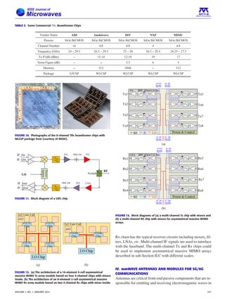
The MPAC method was standardized by the Cellular
Telecommunications Industry Association (CTIA) to test the
LTE downlink MIMO OTA performance in the early years
[182]. It is one of the mainstream methods for testing the
system performance of 5G mmWave devices. Traditionally,
the MPAC uses several probe antennas enclosing the DUT
in a ring. Each probe is connected to an emulator channel
to construct the targeted multipath environment [183]. The
emulation accuracy in the testing area depends on the num-
ber of probes and their positions. For sparse mmWave chan-
nels, a cost-effective sectored MPAC was proposed in [184],
[185], which uses mmWave switching circuits to select the
FIGURE 20. The conceptual setup of the sectored MPAC testing system
[186].
probes with the strongest effect and map them to the mmWave
channel emulators [see Fig. 20] [186]. It can be used to test
the mmWave massive MIMO systems and UEs for both the
line-of-sight (LOS) and non-line-of-sight (NLOS) links. Nev-
ertheless, the system cost and complexity of the MPAC and
sectored MPAC methods are higher than the RC and RTS
methods. In recent years, probe selection algorithms are under
investigation to further reduce the number of active probes.
D. OUTLOOKS OF TESTING METHODS FOR
6G COMMUNICATIONS
Overall, the unlicensed bandwidth is relatively abundant in
mmWave band, but the free-space path loss becomes far
greater than that of the sub-6 GHz band. They force the test-
ing techniques to move to higher frequencies, broader band-
width, and larger dynamic ranges. For the 6G communica-
tions, new potential technologies will raise new challenges in
OTA measurements. First, for asymmetrical wireless systems
mentioned in Section II, the end-to-end system performance
testing is required because the channel matrices for the down-
link and uplink communications are different. This end-to-end
measurement conception has already been reported in [187]
for 5G performance testing and could be utilized fort testing
asymmetrical wireless systems. Secondly, terminal mobility is
characterized as the Doppler shift included in the state-of-art
system performance testing, but it needs to be greatly im-
proved for testing mmWave satellite communications. The dy-
namic target detection, doppler shift of moving directions, and
link stability should all be considered in system performance
testing in an anechoic chamber, as it is nearly impossible to
do in-situ test by launching a satellite.
VI. CHANNEL CHARACTERIZATION
As frequency increases, the channel characteristics in
mmWave bands are significantly different from those in the
sub-6 GHz bands in terms of large-scale and small-scale fad-
ing [188]. Real-world channel sounding results reveal that
mmWave signals are more vulnerable to surrounding block-
ages. Also, the sparsity nature of the channel is discernible,
which poses several challenges for exploiting the advantages
114 VOLUME 1, NO. 1, JANUARY 2021](https://image.slidesharecdn.com/theroleofmillimeter-wavetechnologiesin5g6gwirelesscommunications-240922201956-627b2cbc/85/The_Role_of_Millimeter-Wave_Technologies_in_5G_6G_Wireless_Communications-pdf-14-320.jpg)
![of mmWave communications [189], [190]. Moreover, when
large-scale antenna arrays confined within a limited physical
space are used at BSs, they are expected to provide sufficient
directional beamforming gains to combat severe path loss
at mmWave frequencies. An increasing number of elements,
however, presents several new challenges to be addressed,
such as channel hardening, spherical wave propagation, and
spatial non-stationarity [191]. Therefore, the interaction be-
tween antennas and propagation channel needs to be inves-
tigated in order to meet the requirements of future mmWave
massive MIMO systems.
For mmWave communications, the path losses are gener-
ally much higher especially in NLOS scenarios [189], [190].
Additional losses including shadow fading, blockage effect,
foliage attenuation, and off-body fading (e.g., handset on the
right side of the head) need to be taken into account [192],
[193]. The statistical analysis of these effects can be per-
formed via site-specific measurements rather than conducting
cellular-type measurements. Another issue is that most work
so far mainly focuses on omnidirectional path loss characteri-
zation. The effects of beam patterns and antenna polarization
in different transmission schemes still remain unclear.
The small-scale space-time propagation characteristics play
a critical role in mmWave system designs, including the an-
tennas, RF front-ends, access protocols, and network architec-
tures [188], [193]. Apart from the LOS path, multipath propa-
gation occurs that combines the reflected and diffracted paths.
Thus, it is meaningful to study the reflection and diffraction
over various materials in different frequency bands and at dif-
ferent incident angles. Owing to channel bandwidth increase,
relatively high delay resolution results in multipath effects ob-
servable in mmWave sparse channels. Thus, the delay spread
and power decay for each cluster propagating through a phys-
ical or virtual scatterer need to be estimated. The high spatial
resolution of large-scale antenna arrays can leverage the ben-
efits of 3D beamforming in both the azimuthal and elevation
planes. They will enable higher multi-user capacity, coverage
enhancement, and suppression of multi-cell and inter-beam
interference. A major issue of exploiting the channel’s ele-
vation degree of freedom is that the power consumption will
increase as the elevation angle increases. Consequently, a
full description of the three polarizations of mmWave chan-
nels in a uniform Cartesian coordinate system is necessary.
The recent development of mmWave channel measurement
techniques using virtual antenna arrays reveal that the spaced
elements will observe different sets of clusters (so-called spa-
tial non-stationarity property), which can be modeled as a
birth-death process [191]. Overall, with the knowledge of
propagation characteristics and their interactions with the RF
subsystems, the rapid development of the mmWave technolo-
gies could unlock the full potential of the mmWave spectrum
in the future 5G/6G wireless communication systems.
VII. CONCLUSION
In summary, the key enabling mmWave technologies for 5G
communications are reviewed, including the different kinds
of system architectures, multi-channel beamforming chips,
antennas for BSs and UTs, measurement and calibration
techniques, and wireless channel characterization. The
recent developments are described with examples, and
the requirements and challenges for 6G communications
are also discussed. In general, compared with 5G, the 6G
requires the integration of more physical transceiver channels,
more frequency bands, more operation flexibility, and more
diverse functionalities into a communication system with
considerably superior electrical performance. This calls for
the development of low-power highly-linear multi-channel
chips, multi-band multi-polarization compact antennas and
modules, automated efficient calibration and measurement
methods, multi-dimensional beamforming networks, accurate
multi-spectral multi-stage channel models, and many other
enabling mmWave hardwares and related algorithms. It is
believed that the mmWave technology will play a more and
more important role than it ever has been in future commercial
telecommunication infrastructures.
REFERENCES
[1] G. Falciasecca, “Marconi’s early experiments in wireless telegraphy,
1895,” IEEE Antennas Propag. Mag., vol. 52, no. 6, pp. 220–221,
Dec. 2010.
[2] T. S. Rappaport, Wireless Communications: Principles and Practice,
2nd ed. Englewood Cliffs, NJ, USA: Prentice-Hall, 2002.
[3] A. Goldsmith, Wireless Communications. Cambridge, U.K.: Cam-
bridge Univ., 2005.
[4] J. A. del Peral-Rosado, R. Raulefs, J. A. López-Salcedo, and G.
Seco-Granados, “Survey of cellular mobile radio localization meth-
ods: From 1G to 5G,” IEEE Commun. Surveys Tuts., vol. 20, no. 2,
pp. 1124–1148, 2nd Quart. 2018.
[5] T. Farley, “Mobile telephone history,” Telektronikk, vol. 101, no. 3–4,
pp. 22–34, 2005.
[6] GSM Memorandum of Understanding, Copenhagen, Denmark, Eur.
CEPT, Sep. 1987.
[7] F. Hillebrand, “The creation of standards for global mobile commu-
nication: GSM and UMTS standardization from 1982 to 2000,” IEEE
Wireless Commun., vol. 20, no. 5, pp. 24–33, Oct. 2013.
[8] H. Holma and A. Toskala, WCDMA For UMTS: Radio Access For
Third Generation Mobile Communications. Chichester, U.K.: Wiley,
2000.
[9] S. Abeta, M. Tanno, and M. Iwamura, “Standardization trends in LTE
enhancement,” NTT DOCOMO Tech. J., vol. 12, no. 1, pp. 42–44,
Jun. 2010.
[10] C. Hoymann et al., “LTE release 14 outlook,” IEEE Wireless Com-
mun., vol. 54, no. 6, pp. 44–49, Jun. 2016.
[11] S. Chen and J. Zhao, “The requirements, challenges, and technolo-
gies for 5G of terrestrial mobile telecommunication,” IEEE Commun.
Mag., vol. 52, no. 5, pp. 36–43, May 2014.
[12] J. G. Andrews et al., “Overview of millimeter wave communica-
tions for fifth-generation (5G) wireless networks—With a focus on
propagation models,” IEEE J. Sel. Areas Commun., vol. 32, no. 6,
pp. 1065–1082, Jun. 2014.
[13] W. Saad, M. Bennis, and M. Chen, “A vision of 6G wireless systems:
Applications, trends, technologies, and open research problems,” IEEE
Netw., vol. 34, no. 3, pp. 134–142, May 2020.
[14] A. Osseiran et al., “Scenarios for 5G mobile and wireless communica-
tions: The vision of the METIS project,” IEEE Commun. Mag., vol. 52,
no. 5, pp. 26–35, May 2014.
[15] E. Dahlman et al., “5G wireless access: Requirements and realization,”
IEEE Commun. Mag., vol. 52, no. 12, pp. 42–47, Dec. 2014.
[16] F. Boccardi, R. W. Heath, Jr., A. Lozano, T. L. Marzetta, and P.
Popovski, “Five disruptive technology directions for 5G,” IEEE Com-
mun. Mag., vol. 52, no. 2, pp. 74–80, Feb. 2014.
VOLUME 1, NO. 1, JANUARY 2021 115](https://image.slidesharecdn.com/theroleofmillimeter-wavetechnologiesin5g6gwirelesscommunications-240922201956-627b2cbc/85/The_Role_of_Millimeter-Wave_Technologies_in_5G_6G_Wireless_Communications-pdf-15-320.jpg)
![HONG ET AL.: ROLE OF MILLIMETER-WAVE TECHNOLOGIES IN 5G/6G WIRELESS COMMUNICATIONS
[17] C.-X. Wang et al., “Cellular architecture and key technologies for
5G wireless communication networks,” IEEE Commun. Mag., vol. 52,
no. 2, pp. 122–130, Feb. 2014.
[18] T. S. Rappaport et al., “Millimeter wave mobile communications
for 5G cellular: It will work!,” IEEE Access, vol. 1, pp. 335–349,
May 2013.
[19] J. Qiao, X. Shen, J. Mark, Q. Shen, Y. He, and L. Lei, “En-
abling deviceto-device communications in millimeter-wave 5G cel-
lular networks,” IEEE Commun. Mag., vol. 53, no. 1, pp. 209–215,
Jan. 2015.
[20] NR; Base Station (BS) Radio Transmission and Reception (Release
16), document 3GPP TS 38.104, 2019.
[21] J. Lee et al., “Spectrum for 5G: Global status, challenges, and en-
abling technologies,” IEEE Commun. Mag., vol. 56, no. 3, pp. 12–18,
Mar. 2018.
[22] W. Hong et al., “Multibeam antenna technologies for 5G wireless
communications,” IEEE Trans. Antennas Propag., vol. 65, no. 12,
pp. 6231–6249, Dec. 2017.
[23] J. Kibilda et al., “Indoor millimeter-wave systems: Design and per-
formance evaluation,” Proc. IEEE, vol. 108, no. 6, pp. 923–944, Jun.
2020.
[24] Y. Wang et al., “A 39-GHz 64-element phased-array transceiver
with built-in phase and amplitude calibrations for large-array 5G
NR in 65-nm CMOS,” IEEE J. Solid-State Circuits, vol. 55, no. 5,
pp. 1249–1269, May 2020.
[25] T. S. Rappaport, Y. Xing, G. R. MacCartney, A. F. Molisch, E.
Mellios, and J. Zhang, “Overview of millimeter wave communica-
tions for fifth-generation (5G) wireless networks—With a focus on
propagation models,” IEEE Trans. Antennas Propag., vol. 65, no. 12,
pp. 6213–6230, Dec. 2017.
[26] H. Viswanathan and P. E. Mogensen, “Communications in the 6G era,”
IEEE Access, vol. 8, pp. 57063–57074, Mar. 2020.
[27] T. S. Rappaport et al., “Wireless communications and applications
above 100 GHz: Opportunities and challenges for 6G and beyond,”
IEEE Access, vol. 7, pp. 78729–78757, Mar. 2019.
[28] B. Yang, Z. Yu, R. Zhang, J. Zhou, and W. Hong, “Local oscillator
phase shifting and harmonic mixing-based high-precision phased ar-
ray for 5G millimeter-wave communications,” IEEE Trans. Microw.
Theory Techn., vol. 67, no. 7, pp. 3162–3173, Jul. 2019.
[29] R. Zhang, J. Zhou, J. Lan, B. Yang, and Z. Yu, “A high-
precision hybrid analog and digital beamforming transceiver sys-
tem for 5G millimeter-wave communication,” IEEE Access, vol. 7,
pp. 83012–83023, Jun. 2019.
[30] M. Jiang, Z. N. Chen, Y. Zhang, W. Hong, and X. Xuan, “Meta-
material based thin planar lens antenna for spatial beamforming and
multibeam massive MIMO,” IEEE Trans. Antennas Propag., vol. 65,
no. 2, pp. 464–472, Feb. 2017.
[31] S.-S. Jeon, Y. Wang, Y. Qian, and T. Itoh, “A novel smart an-
tenna system implementation for broad-band wireless communica-
tions,” IEEE Trans. Antennas Propag., vol. 50, no. 5, pp. 600–606,
May 2002.
[32] D. Kang, K. Koh, and G. M. Rebeiz, “A Ku-band two-antenna
four-simultaneous beams sige BiCMOS phased array receiver,” IEEE
Trans. Microw. Theory Techn., vol. 58, no. 4, pp. 771–780, Apr. 2010.
[33] M. Sayginer and G. M. Rebeiz, “An eight-element 2–16-GHz pro-
grammable phased array receiver with one two or four simultaneous
beams in sige BiCMOS,” IEEE Trans. Microw. Theory Techn., vol. 64,
no. 12, pp. 4585–4597, Dec. 2016.
[34] K. Tekkouk, J. Hirokawa, R. Sauleau, M. Ettorre, M. Sano, and M.
Ando, “Dual-layer ridged waveguide slot array fed by a butler matrix
with sidelobe control in the 60-GHz band,” IEEE Trans. Antennas
Propag., vol. 63, no. 9, pp. 3857–3867, Sep. 2015.
[35] P. Chen, W. Hong, Z. Kuai, and J. Xu, “A double layer substrate
integrated waveguide blass matrix for beamforming applications,”
IEEE Microw. Wireless Compon. Lett., vol. 19, no. 6, pp. 374–376,
Jun. 2009.
[36] Y. Zeng, R. Zhang, and Z. N. Chen, “Electromagnetic lens-focusing
antenna enabled massive MIMO: Performance improvement and
cost reduction,” IEEE J. Sel. Areas Commun., vol. 32, no. 6,
pp. 1194–1206, Jun. 2014.
[37] R. Valkonen, “Compact 28-GHz phased array antenna for 5G access,”
in IEEE MTT-S Int. Microw. Symp. Dig., Philadelphia, PA, USA, Jun.
2018, pp. 1334–1337.
[38] B. Yang, Z. Yu, J. Lan, R. Zhang, J. Zhou, and W. Hong, “Digital
beamforming-based massive MIMO transceiver for 5G millimeter-
wave communications,” IEEE Trans. Microw. Theory Techn., vol. 66,
no. 7, pp. 3403–3418, May 2018.
[39] C. Yu et al., “Full-angle digital predistortion of 5G millimeter-wave
massive MIMO transmitters,” IEEE Trans. Microw. Theory Techn.,
vol. 67, no. 7, pp. 2847–2860, Jul. 2019.
[40] L. Kuai et al., “A N260 band 64 channel millimeter wave full-digital
multi-beam array for 5G massive MIMO applications,” IEEE Access,
vol. 8, pp. 47640–47653, Mar. 2020.
[41] M. M. Molu, P. Xiao, M. Khalily, K. Cumanan, L. Zhang, and R.
Tafazolli, “Low-complexity and robust hybrid beamforming design for
multi-antenna communication systems,” IEEE Trans. Wireless Com-
mun., vol. 17, no. 3, pp. 1445–1459, Dec. 2018.
[42] J. A. Zhang, X. Huang, V. Dyadyuk, and Y. J. Guo, “Massive hybrid
antenna array for millimeter-wave cellular communications,” IEEE
Wireless Commun, vol. 22, no. 1, pp. 79–87, Feb. 2015.
[43] X. Liu et al., “Beam-oriented digital predistortion for 5G massive
MIMO hybrid beamforming transmitters,” IEEE Trans. Microw. The-
ory Techn., vol. 66, no. 7, pp. 3419–3432, Jul. 2018.
[44] S. Payami et al., “Developing the first MMWave fully-connected hy-
brid beamformer with a large antenna array,” IEEE Access, vol. 8,
pp. 141282–114129, Jul. 2020.
[45] Y. Gao, M. Khaliel, F. Zheng, and T. Kaiser, “Rotman lens
based hybrid analog–digital beamforming in massive MIMO sys-
tems: Array architectures, beam selection algorithms and experi-
ments,” IEEE Trans. Veh. Technol., vol. 66, no. 10, pp. 9134–9148,
Jun. 2017.
[46] Y. Hu and W. Hong, “A novel hybrid analog-digital multibeam an-
tenna array for massive MIMO applications,” in Proc. IEEE Asia-
Pacific Conf. Antennas Propag., Auckland, New Zealand, Aug. 2018,
pp. 42–45.
[47] J. D. Dunworth et al., “A 28 GHz bulk-CMOS dual-polarization
phased-array transceiver with 24 channels for 5G user and base sta-
tion equipment,” in Proc. IEEE Int. Solid-State Circuits Conf., San
Francisco, CA, USA, Feb. 2018, pp. 70–72.
[48] W. He, B. Xu, Y. Yao, D. Colombi, Z. Ying, and S. He, “Impli-
cations of incident power density limits on power and EIRP lev-
els of 5G millimeter-wave user equipment,” IEEE Access, vol. 8,
pp. 148214–148225, Aug. 2020.
[49] D. Liu, X. Gu, C. W. Baks, and A. Valdes-Garcia, “Antenna-
in-package design considerations for Ka-band 5G communication
applications,” IEEE Trans. Antennas Propag., vol. 65, no. 12,
pp. 6372–6379, Dec. 2017.
[50] T. Kuwabara, N. Tawa, Y. Tone, and T. Kaneko, “A 28 GHz
480 elements digital AAS using GaN HEMT amplifiers with
68 dBm EIRP for 5G long-range base station applications,” in
Proc. IEEE Compound Semicond. Integr. Circuit Symp., Oct. 2017,
pp. 1–4.
[51] J. Park, S. Y. Lee, Y. Kim, J. Lee, and W. Hong, “Hybrid antenna
module concept for 28 GHz 5G beamsteering cellular devices,” in
Proc. IEEE MTT-S Int. Microw. Workshop Ser. 5G Hardware Syst.
Technol., Dublin, Ireland, pp. 1–3, Aug. 2018.
[52] C. I. Q. Sun, Z. Liu, S. Zhang, and S. Han, “The big-data-driven
intelligent wireless network: Architecture, use cases, solutions, and
future trends,” IEEE Veh. Technol. Mag., vol. 12, no. 4, pp. 20–29,
Dec. 2017.
[53] J. Liu, Y. Shi, Z. M. Fadlullah, and N. Kato, “Space-air-ground inte-
grated network: A survey,” IEEE Commun. Surveys Tuts., vol. 20, no.
4, pp. 2714–2741, Fourth quarter 2018.
[54] J. Foust, “SpaceX’s space-Internet woes: Despite technical glitches,
the company plans to launch the first of nearly 12,000 satellites in
2019,” IEEE Spectr., vol. 56, no. 1, pp. 50–51, Jan. 2019.
[55] I. del Portillo Barrios, B. Cameron, and E. Crawley, “A techni-
cal comparison of three low earth orbit satellite constellation sys-
tems to provide global broadband,” Acta Astronautica, vol. 159,
2019.
[56] C. G. Christodoulou, Y. Tawk, S. A. Lane, and S. R. Erwin, “Recon-
figurable antennas for wireless and space applications,” Proc. IEEE,
vol. 100, no. 7, pp. 2250–2261, Jul. 2012.
[57] K. B. Letaief, W. Chen, Y. Shi, J. Zhang, and Y. A. Zhang, “The
roadmap to 6G: AI empowered wireless networks,” IEEE Commun.
Mag., vol. 57, no. 8, pp. 84–90, Aug. 2019.
116 VOLUME 1, NO. 1, JANUARY 2021](https://image.slidesharecdn.com/theroleofmillimeter-wavetechnologiesin5g6gwirelesscommunications-240922201956-627b2cbc/85/The_Role_of_Millimeter-Wave_Technologies_in_5G_6G_Wireless_Communications-pdf-16-320.jpg)
![[58] C. Wang, M. D. Renzo, S. Stanczak, S. Wang, and E. G. Larsson, “Ar-
tificial intelligence enabled wireless networking for 5G and beyond:
Recent advances and future challenges,” IEEE Wireless Commun.,
vol. 27, no. 1, pp. 16–23, Feb. 2020.
[59] J. Riihijarvi and P. Mahonen, “Machine learning for performance
prediction in mobile cellular networks,” IEEE Comput. Intell. Mag.,
vol. 13, no. 1, pp. 51–60, Feb. 2018.
[60] C. Guo et al., “Design and implementation of a full-digital beam-
forming array with nonreciprocal tx/rx beam patterns,” IEEE Antennas
Wireless Propag. Lett., vol. 19, no. 11, pp. 1978–1982, Nov. 2020.
[61] K. Kibaroglu, M. Sayginer, T. Phelps, and G. M. Rebeiz, “A 64-
element 28-GHz phased-array transceiver with 52-dBm EIRP and
8–12-Gb/s 5G link at 300 meters without any calibration,” IEEE Trans.
Microw. Theory Techn., vol. 66, no. 12, pp. 5796–5811, Dec. 2018.
[62] K. Kibaroglu, M. Sayginer, and G. M. Rebeiz, “A low-cost scalable
32-element 28-GHz phased array transceiver for 5G communication
links based on a 2 × 2 beamformer flip-chip unit cell,” IEEE J. Solid-
State Circuits, vol. 53, no. 5, pp. 1260–1274, May 2018.
[63] B. Sadhu et al., “A 28-GHz 32-element TRX phased-array IC with
concurrent dual-polarized operation and orthogonal phase and gain
control for 5G communications,” IEEE J. Solid-State Circuits, vol. 52,
no. 12, pp. 3373–3391, Dec. 2017.
[64] J. Pang et al., “A 28-GHz CMOS phased-array transceiver based on
LO phase-shifting architecture with gain invariant phase tuning for 5G
new radio,” IEEE J. Solid-State Circuits, vol. 54, no. 5, pp. 1228–1242,
May 2019.
[65] C. A. Balanis, Antenna Theory: Analysis and Design, 4th ed. Hoboken,
NY, USA: Wiley, 2016.
[66] W. Hong, K.-H. Baek, and S. Ko, “Millimeter-wave 5G antennas
for smartphones: Overview and experimental demonstration,” IEEE
Trans. Antennas Propag., vol. 65, no. 12, pp. 6250–6261, Dec. 2017.
[67] T. E. Bogale and L. B. Le, “Massive MIMO and MMWave for 5G
wireless hetnet: Potential benefits and challenges,” IEEE Veh. Technol.
Mag., vol. 11, no. 1, pp. 64–75, Mar. 2016.
[68] Z. N. Chen and K.-M. Luk, Antenna For Base Stations in Wireless
Communications. New York, NY, USA: McGraw-Hill, 2009.
[69] G. M. Rebeiz, “Millimeter-wave and terahertz integrated circuit anten-
nas,” Proc. IEEE, vol. 80, no. 11, pp. 1748–1770, Nov. 1992.
[70] B. Yang, Z. Yu, Y. Dong, J. Zhou, and W. Hong, “Compact tapered slot
antenna array for 5G millimeter-wave massive MIMO systems,” IEEE
Trans. Antennas Propag., vol. 65, no. 12, pp. 6721–6727, Dec. 2017.
[71] K.-M. Mak, K. K. So, H.-W. Lai, and K.-M. Luk, “A magnetoelectric
dipole leaky-wave antenna for millimeter-wave application,” IEEE
Trans. Antennas Propag., vol. 65, no. 12, pp. 6395–6402, Dec. 2017.
[72] Y. Zhu, R. Lu, C. Yu, and W. Hong, “Design and implementation
of a wideband antenna subarray for phased array applications,” IEEE
Trans. Antennas Propag., vol. 68, no. 8, pp. 6059–6068, Dec. 2020.
[73] T. Li and Z. N. Chen, “Wideband sidelobe-level reduced Ka-band
metasurface antenna array fed by substrate-integrated gap waveguide
using characteristic mode analysis,” IEEE Trans. Antennas Propag.,
vol. 68, no. 3, pp. 1356–1365, Mar. 2020.
[74] D. J. Bisharat, S. Liao, and Q. Xue, “High gain and low cost differ-
entially fed circularly polarized planar aperture antenna for broadband
millimeter-wave applications,” IEEE Trans. Antennas Propag., vol. 64,
no. 1, pp. 33–42, Jan. 2016.
[75] K. Schneider, S. Marahrens, J. Eisenbeis, J. Kowalewski, and T.
Zwick, “Broadband dual-polarized stacked microstrip antenna with
pin- and edge-feed for 5G applications in Ka-band,” in Proc. 14th Eur.
Conf. Antennas Propag., Copenhagen, Denmark, Mar. 2020, pp. 1–5.
[76] Q. Yang et al., “Millimetre-wave dual-polarized differentially-fed 2D
multibeam patch antenna array,” IEEE Trans. Antennas Propag., 2020,
early access, doi: 10.1109/TAP.2020.2992896.
[77] H. Chu and Y. Guo, “A filtering dual-polarized antenna subarray tar-
geting for base stations in millimeter-wave 5G wireless communica-
tions,” IEEE Trans. Compon. Packag. Manuf. Technol., vol. 7, no. 6,
pp. 964–973, Jun. 2017.
[78] Y. Li and K.-M. Luk, “60-GHz dual-polarized two-dimensional switch
beam wideband antenna array of aperture-coupled magneto-electric
dipoles,” IEEE Trans. Antennas Propag., vol. 64, no. 2, pp. 554–563,
Feb. 2016.
[79] S. J. Yang, Y. M. Pan, L.-Y. Shi, and X. Y. Zhang, “Millimeter-wave
dual-polarized filtering antenna for 5G application,” IEEE Trans. An-
tennas Propag., vol. 68, no. 7, pp. 5114–5121, Jul. 2020.
[80] T. Li and Z. N. Chen, “A dual-band metasurface antenna using char-
acteristic mode analysis,” IEEE Trans. Antennas Propag., vol. 66,
no. 10, pp. 5620–5624, Oct. 2018.
[81] Q. Wu, J. Hirokawa, J. Yin, C. Yu, H. Wang, and W. Hong,
“Millimeter-wave multibeam endfire dual-circularly polarized antenna
array for 5G wireless applications,” IEEE Trans. Antennas Propag.,
vol. 66, no. 9, pp. 4930–4935, Sep. 2018.
[82] W. M. Dyab, A. A. Sakr, and K. Wu, “Dually-polarized butler matrix
for base stations with polarization diversity,” IEEE Trans. Microw.
Theory Techn., vol. 66, no. 12, pp. 5543–5553, Dec. 2018.
[83] H.-T. Chou, S.-J. Chou, C.-W. Chiu, C.-C. Sun, and C.-T. Yu,
“Quasi-orthogonal multibeam radiation of reflector antennas for ra-
dio coverage of mobile communication at millimeter-wave frequen-
cies,” IEEE Trans. Antennas Propag., vol. 66, no. 11, pp. 6340–6345,
Nov. 2018.
[84] Z. H. Jiang, Y. Zhang, J. Xu, Y. Yu, and W. Hong, “Integrated
broadband circularly polarized multibeam antennas using Berry-phase
transmit-arrays for Ka-band applications,” IEEE Trans. Antennas
Propag., vol. 68, no. 2, pp. 859–872, Feb. 2020.
[85] Z. Ying, “Antennas in cellular phones for mobile communications,”
Proc. IEEE, vol. 100, no. 7, pp. 2286–2296, Jul. 2012.
[86] W. Hong, “Solving the 5G mobile antenna puzzle: Assessing future
directions for the 5G mobile antenna paradigm shift,” IEEE Microw.
Mag., vol. 18, no. 7, pp. 86–102, Dec. 2017.
[87] General Aspects for User Equipment (UE) Radio Frequency (RF) for
NR (Release 15), document 38.817-1, 3GPP, 2019.
[88] J. Helander, K. Zhao, Z. Ying, and D. Sjöberg, “Performance anal-
ysis of millimeter-wave phased array antennas in cellular hand-
sets,” IEEE Antennas Wireless Propag. Lett., vol. 15, pp. 504–507,
2016.
[89] R. Khan, A. A. Al-Hadi, P. J. Soh, M. R. Kamarudin, M. T. Ali,
and Owais, “User influence on mobile terminal antennas: A review
of challenges and potential solution for 5G antennas,” IEEE Access,
vol. 6, pp. 77695–77715, Nov. 2018.
[90] S. Shinjo, K. Nakatani, K. Tsutsumi, and H. Nakamizo, “Integrating
the front end: A highly integrated RF front end for high-SHF wide-
band massive MIMO in 5G,” IEEE Microw. Mag., vol. 18, no. 5,
pp. 31–40, Aug. 2017.
[91] W. Hong, K.-H. Baek, Y. Lee, Y. Kim, and S.-T. Ko, “Study and
prototyping of practically large-scale MMWave antenna systems for
5G cellular devices,” IEEE Commun. Mag., vol. 52, no. 9, pp. 63–69,
Sep. 2014.
[92] R. Suga, H. Nakano, Y. Hirachi, J. Hirokawa, and M. Ando, “Cost-
effective 60-GHz antenna package with end-fire radiation for wireless
file-transfer system,” IEEE Trans. Microw. Theory Techn., vol. 58, no.
12, pp. 3989–3995, Dec. 2010.
[93] S. Zhang, I. Syrytsin, and G. F. Pedersen, “Compact beam-steerable
antenna array with two passive parasitic elements for 5G mobile ter-
minals at 28 GHz,” IEEE Trans. Antennas Propag., vol. 66, no. 10,
pp. 5193–5203, Oct. 2018.
[94] J. Zeng and K. Luk, “Wideband millimeter-wave end-fire magneto-
electric dipole antenna with microstrip-line feed,” IEEE Trans. Anten-
nas Propag., vol. 68, no. 4, pp. 2658–2665, Apr. 2020.
[95] B. Yu, K. Yang, C.-Y.-D. Sim, and G. Yang, “A novel 28 GHz beam
steering array for 5G mobile device with metallic casing applica-
tion,” IEEE Trans. Antennas Propag., vol. 66, no. 1, pp. 462–466,
Jan. 2018.
[96] J. Choi et al., “Frequency-adjustable planar folded slot antenna us-
ing fully integrated multithrow function for 5G mobile devices at
millimeter-wave spectrum,” IEEE Trans. Microw. Theory Techn.,
vol. 68, no. 5, pp. 1872–1881, May 2020.
[97] C. Di Paola, S. Zhang, K. Zhao, Z. Ying, T. Bolin, and G. F. Pedersen,
“Wideband beam-switchable 28 GHz quasi-Yagi array for mobile de-
vices,” IEEE Trans. Antennas Propag., vol. 67, no. 11, pp. 6870–6882,
Nov. 2018.
[98] I. Syrytsin, S. Zhang, G. F. Pedersen, and A. S. Morris, III, “Compact
quad-mode planar phased array with wideband for 5G mobile termi-
nals,” IEEE Trans. Antennas Propag., vol. 66, no. 9, pp. 4648–4657,
Sep. 2018.
[99] S. Zhang, X. Chen, I. Syrytsin, and G. F. Pedersen, “A planar switch-
able 3-D-coverage phased array antenna and its user effects for 28-
GHz mobile terminal applications,” IEEE Trans. Antennas Propag.,
vol. 65, no. 12, pp. 6413–6421, Dec. 2017.
VOLUME 1, NO. 1, JANUARY 2021 117](https://image.slidesharecdn.com/theroleofmillimeter-wavetechnologiesin5g6gwirelesscommunications-240922201956-627b2cbc/85/The_Role_of_Millimeter-Wave_Technologies_in_5G_6G_Wireless_Communications-pdf-17-320.jpg)
![HONG ET AL.: ROLE OF MILLIMETER-WAVE TECHNOLOGIES IN 5G/6G WIRELESS COMMUNICATIONS
[100] R. Rodriguez-Cano, S. Zhang, K. Zhao, and G. F. Pedersen, “mm-
Wave beam-steerable endfire array embedded in a slotted metal-
frame LTE antenna,” IEEE Trans. Antennas Propag., vol. 68, no. 5,
pp. 3685–3694, May 2020.
[101] Y.-W. Hsu, T.-C. Huang, H.-S. Lin, and Y.-C. Lin, “Dual-polarized
quasi Yagi-Uda antennas with endfire radiation for millimeter-wave
MIMO terminals,” IEEE Trans. Antennas Propag., vol. 65, no. 12,
pp. 6282–6289, Dec. 2017.
[102] O. Jo, J.-J. Kim, J. Yoon, D. Choi, and W. Hong, “Exploitation
of dual-polarization diversity for 5G millimeter-wave MIMO beam-
forming systems,” IEEE Trans. Antennas Propag., vol. 65, no. 12,
pp. 6646–6655, Dec. 2017.
[103] A. Li, K.-M. Lu, and Y. Li, “A dual linearly polarized end-fire antenna
array for the 5G applications,” IEEE Access, vol. 6, pp. 78276–78285,
Dec. 2018.
[104] J. Zhang, K. Zhao, L. Wang, S. Zhang, and G. F. Pedersen, “Dual-
polarized phased array with end-fire radiation for 5G handset applica-
tions,” IEEE Trans. Antennas Propag., vol. 68, no. 4, pp. 3277–3282,
Apr. 2020.
[105] R. M. Moreno et al., “Dual-polarized mm-Wave end-fire chain-slot
antenna for mobile devices,” IEEE Trans. Antennas Propag., early
access, 2020.
[106] R. Khan, A. A. Al-Hadi, and P. J. Soh, “Recent advancements
in user effect mitigation for mobile terminal antennas: A review,”
IEEE Trans. Electromagn. Compat., vol. 61, no. 1, pp. 279–287,
Feb. 2019.
[107] I. Syrytsin, S. Zhang, G. F. Pedersen, K. Zhao, T. Bolin, and Z. Ying,
“Statistical investigation of the user effects on mobile terminal anten-
nas for 5G applications,” IEEE Trans. Antennas Propag., vol. 65, no.
12, pp. 6596–6605, Dec. 2017.
[108] G. Q. Luo et al., “Filtenna consisting of horn antenna and substrate
integrated waveguide cavity FSS,” IEEE Trans. Antennas Propag.,
vol. 55, no. 1, pp. 92–98, Jan. 2007.
[109] Y. Yusuf and X. Gong, “Compact low-loss integration of high-Q 3-
D filters with highly efficient antennas,” IEEE Trans. Microw. Theory
Technol., vol. 59, no. 4, pp. 857–865, Apr. 2011.
[110] Z. H. Jiang and D. H. Werner, “A compact, wideband circularly po-
larized co-designed filtering antenna and its application for wearable
devices with low SAR,” IEEE Trans. Antennas Propag., vol. 63, no. 9,
pp. 3808–3818, Sep. 2015.
[111] X. Y. Zhang, W. Duan, and Y.-M. Pan, “High-gain filtering patch
antenna without extra circuit,” IEEE Trans. Antennas Propag., vol. 63,
no. 2, pp. 5883–5888, Feb. 2015.
[112] J. F. Zhang, Y. J. Cheng, Y. R. Ding, and C. X. Bai, “A dual-band
shared-aperture antenna with large frequency ratio, high aperture reuse
efficiency, and high channel isolation,” IEEE Trans. Antennas Propag.,
vol. 67, no. 2, pp. 853–860, Feb. 2019.
[113] T. Li and Z. N. Chen, “Shared-surface dual-band antenna for
5G applications,” IEEE Trans. Antennas Propag., vol. 68, no. 2,
pp. 1128–1133, Feb. 2020.
[114] J. Lan, Z. Yu, J. Zhou, and W. Hong, “An aperture-sharing array
for (3.5, 28) GHz terminals with steerable beam in millimeter-wave
band,” IEEE Trans. Antennas Propag., vol. 68, no. 5, pp. 4114–4119,
May 2020.
[115] Y. Liu, Y. Li, L. Ge, J. Wang, and B. Ai, “A compact hepta-
band mode-composite antenna for sub (6, 28, and 38) GHz applica-
tions,” IEEE Trans. Antennas Propag., vol. 68, no. 4, pp. 2593–2602,
Apr. 2020.
[116] M. S. Sharawi, M. Ikram, and A. Shamim, “A two concentric slot
loop based connected array MIMO antenna system for 4G/5G termi-
nals,” IEEE Trans. Antennas Propag., vol. 65, no. 12, pp. 6679–6686,
Dec. 2017.
[117] Y. P. Zhang and J. Mao, “An overview of the development
of antenna-in-package technology for highly integrated wireless
devices,” Proc. IEEE, vol. 107, no. 11, pp. 2265–2280, Nov.
2019.
[118] Y. P. Zhang and D. Liu, “Antenna-on-chip and antenna-in-package
solutions to highly integrated millimeter-wave devices for wireless
communications,” IEEE Trans. Antennas Propag., vol. 57, no. 10,
pp. 2830–2841, Oct. 2009.
[119] W. Hong, K. H. Baek, and A. Goudelev, “Grid assembly-free 60-GHz
antenna module embedded in FR-4 transceiver carrier board,” IEEE
Trans. Antennas Propag., vol. 61, no. 4, pp. 1573–1580, Apr. 2013.
[120] D. Liu, J. A. G. Akkermans, H.-C. Chen, and B. Floyd, “Packages with
integrated 60-GHz aperture-coupled patch antennas,” IEEE Trans. An-
tennas Propag., vol. 59, no. 10, pp. 3607–3616, Oct. 2011.
[121] D. Liu, X. Gu, C. W. Baks, and A. Valdes-Garcia, “Antenna-
in-package design considerations for Ka-band 5G communication
applications,” IEEE Trans. Antennas Propag., vol. 65, no. 12,
pp. 6372–6379, Dec. 2017.
[122] X. Gu et al., “Development, implementation, and characterization of
a 64-Element dual-polarized phased-array antenna module for 28-
GHz high-speed data communications,” IEEE Trans. Microw. Theory
Techn., vol. 67, no. 7, pp. 2975–2984, Jul. 2019.
[123] E. Degirmenci, “EMF test report: Ericsson AIR 5121,” Ericsson AB,
Stockholm, Sweden, Tech. Rep. GFTB-17:001589, Jan. 2018.
[124] Y. Aslan, C. E. Kiper, A. J. van den Biggelaar, U. Johannsen, and A.
Yarovoy, “Passive cooling of mm-wave active integrated 5G base sta-
tion antennas using CPU heatsinks,” Proc. 16th EuRAD, Paris, France,
Oct. 2019, pp. 121–124.
[125] J. Park, H. Seong, Y. N. Whang, and W. Hong, “Energy-efficient 5G
phased arrays incorporating vertically polarized endfire planar folded
slot antenna for MMWave mobile terminals,” IEEE Trans. Antennas
Propag., vol. 68, no. 1, pp. 230–241, Jan. 2020.
[126] C.-F. Huang and L. Chen, “Realization of printed-on-display antenna
for mobile terminals,” Electron. Lett., vol. 38, no. 20, pp. 1162–1163,
Sep. 2002.
[127] H. J. Song, T. Y. Hsu, D. F. Sievenpiper, H. P. Hsu, J. Schaffner, and
E. Yasan, “A method for improving the efficiency of transparent film
antennas,” IEEE Antennas Wireless Propag. Lett., vol. 7, pp. 753–756,
2008.
[128] F. Colombel, X. Castel, M. Himdi, G. Legeay, S. Vigneron, and E.
M. Cruz, “Ultrathin metal layer, ITO film and ITO/Cu/ITO multilayer
towards transparent antenna,” IET Sci. Meas. Technol., vol. 3, no. 3,
pp. 229–234, May 2009.
[129] J. Park, S. Y. Lee, J. Kim, D. Park, W. Choi, and W. Hong, “An
optically invisible antenna-on-display concept for millimeter-wave
5G cellular devices,” IEEE Trans. Antennas Propag., vol. 67, no. 5,
pp. 2942–2952, May 2019.
[130] NR; Base Station (BS) Conformance Testing Part 2: Radiated Confor-
mance Testing (Release 16), document 3GPP TS 38.141-2, 2019.
[131] NR; User Equipment (UE) Conformance Specification; Radio Trans-
mission and Reception; Part 2: Range 2 Standalone (Release 16),
document 3GPP TS 38.521-2, 2019.
[132] E. G. Larsson, O. Edfors, F. Tufvesson, and T. L. Marzetta, “Massive
MIMO for next generation wireless systems,” IEEE Commun. Mag.,
vol. 52, no. 2, pp. 186–195, Feb. 2014.
[133] K. T. Selvan and R. Janaswamy, “Fraunhofer and Fresnel distances:
Unified derivation for aperture antennas,” IEEE Antennas Propag.
Mag., vol. 59, no. 4, pp. 12–15, Aug. 2017.
[134] S. Mano and T. Katagi, “A method for measuring amplitude and phase
of each radiating element of a phased array antenna,” Trans. IECE,
vol. J65-B, no. 5, pp. 555–560, May 1982.
[135] T. Takahashi, H. Miyashita, Y. Konishi, and S. Makino, “Theoretical
study on measurement accuracy of rotating element electric field vec-
tor (REV) method,” Commun. Jpn., vol. 90, no. 1, pp. 22–33, 2006.
[136] Y. Yu, W. Hong, Z. H. Jiang, H. Zhang, and C. Guo, “Multi-beam
generation and measurement of a DDS-based digital beam-forming
array transmitter at Ka-band,” IEEE Trans. Antennas Propag., vol. 67,
no. 5, pp. 3030–3039, Jan. 2019.
[137] T. Takahashi et al., “Fast measurement technique for phased ar-
ray calibration,” IEEE Trans. Antennas Propag., vol. 56, no. 7,
pp. 1888–1899, Jul. 2008.
[138] T. Takahashi et al., “A novel amplitude-only measurement method
to determine element fields in phased arrays,” IEEE Trans. Antennas
Propag., vol. 60, no. 7, pp. 3222–3230, Jul. 2012.
[139] S. D. Silverstein, “Application of orthogonal codes to the calibration
of active phased array antennas for communication satellites,” IEEE
Trans. Signal Process., vol. 45, no. 1, pp. 206–218, Jan. 1997.
[140] R. Long, J. Ouyang, F. Yang, W. Han, and L. Zhou, “Multi-
element phased array calibration method by solving linear equa-
tions,” IEEE Trans. Antennas Propag., vol. 65, no. 6, pp. 2931–2939,
Jun. 2017.
[141] H. Yang, J. Jang, T. Sun, K. Kim, and S. Choi, “Calibration method
using the zadoff-chu sequence,” in Proc. Int. Conf. ICT Convergence,
Jeju, South Korea, Dec. 2013, pp. 319–324.
118 VOLUME 1, NO. 1, JANUARY 2021](https://image.slidesharecdn.com/theroleofmillimeter-wavetechnologiesin5g6gwirelesscommunications-240922201956-627b2cbc/85/The_Role_of_Millimeter-Wave_Technologies_in_5G_6G_Wireless_Communications-pdf-18-320.jpg)
![[142] S. Qin, X. Ma, and W. Sheng, “Design and measurement of chan-
nel calibration for digital array with orthogonal codes,” in Proc. Int.
Conf. Microw. Millimeter Wave Technol., Shenzhen, China, May 2012,
pp. 1–4.
[143] S. Park, H.-S. Lee, and J.-G. Yook, “Orthogonal code-based trans-
mitted radiation pattern measurement method for 5G massive MIMO
antenna systems,” IEEE Trans. Antennas Propag., vol. 68, no. 5,
pp. 4007–4013, May 2020.
[144] S. Smith et al., “A millimeter-wave antenna amplitude and phase
measurement system,” IEEE Trans. Antennas Propag., vol. 60, no. 4,
pp. 1744–1756, Apr. 2012.
[145] Y. Hu, S. Wang, and S. An, “Over the air testing and error analysis of
5G active antenna system base station in compact antenna test range,”
in Proc. Photon. Electromagn. Res. Symp. Fall, Xiamen, China, Dec.
2019, pp. 1–4.
[146] S. F. Gregson and C. G. Parini, “Use of OTA system performance
metrics in the design and optimization of CATRs for 5G testing,”
in Proc. Antenna Meas. Technol. Assoc., San Diego, CA, USA, Oct.
2019, pp. 1–5.
[147] J. J. Lee, E. M. Ferrer, D. P. Woollen, and K. M. Lee, “Near-field
probe used as a diagnostic tool to locate defective elements in an
array antenna,” IEEE Trans. Antennas Propag., vol. AP-36, no. 3,
pp. 884–889, Jun. 1988.
[148] R. Long, J. Ouyang, F. Yang, Y. Li, K. Zhang, and L. Zhou, “Calibra-
tion method of phased array based on near-field measurement system,”
in Proc. IEEE Antennas Propag. Soc. Int. Symp., Memphis, TN, USA,
Jul. 2014, pp. 1161–1162.
[149] J. Lundgren et al., “A near-field measurement and calibration tech-
nique: Radio-frequency electromagnetic field exposure assessment of
millimeter-wave 5G devices,” IEEE Antennas Propag. Mag., early
access, doi: 10.1109/TAP.2020.2988517.
[150] G. F. Hamberger, C. Rowell, and B. Derat, “Near-field techniques for
millimeter-wave antenna array calibration,” in Proc. Antenna Meas.
Technol. Assoc., San Diego, CA, USA, Oct. 2019, pp. 1–5.
[151] D. Novotny et al., “Performance evaluation of a robotically con-
trolled millimeter-wave near-field pattern range at the NIST,” in Proc.
7th Eur. Conf. Antennas Propag., Gothenburg, Sweden, Apr. 2013,
pp. 4086–4089.
[152] A. Yaghjian, “An overview of near-field antenna measurementss,”
IEEE Trans. Antennas Propag., vol. 34, no. 1, pp. 30–45, Jan. 1986.
[153] S. F. Razavi and Y. Rahmat-Samii, “A new look at phaseless pla-
nar near-field measurements: Limitations, simulations, measurements,
and a hybrid solution,” IEEE Antennas Propag. Mag., vol. 49, no. 2,
pp. 170–178, 2007.
[154] A. Capozzoli, C. Curcio, G. D’Elia, and A. Liseno, “Millimeter-wave
phaseless antenna characterization,” IEEE Trans. Instrum. Meas.,
vol. 57, no. 7, Jul. 2008.
[155] S. Costanzo, G. Di Massa, and M. D. Migliore, “A novel hybrid
approach for far-field characterization from near-field amplitude-only
measurements on arbitrary scanning surfaces,” IEEE Trans. Antennas
Propag., vol. 53, no. 6, pp. 1866–1874, Jun. 2005.
[156] O. M. Bucci, G. D’Elia, G. Leone, and R. Pierri, “Far field pat-
tern determination from the near-field amplitude on two surfaces,”
IEEE Trans. Antennas Propag., vol. 38, no. 11, pp. 1771–1779,
Nov. 1990.
[157] R. Pierri, G. D’Elia, and F. Soldovieri, “A two probes scanning phase-
less near-field far-field transformation technique,” IEEE Trans. Anten-
nas Propag., vol. 47, no. 5, pp. 792–802, May 1999.
[158] H. Kong, Y. Jing, Z. Wen, and M. Yau, “A compact millimeter wave
(MMWave) mid-field over the air (OTA) RF performance test system
for 5G massive MIMO devices,” in Proc. MTT-S Int. Wireless Symp.,
Chengdu, China, May 2018, pp. 1–4.
[159] H. Kong, Z. Wen, Y. Jing, and M. Yau, “Midfield over-the-air
test: A new OTA RF performance test method for 5G massive
MIMO devices,” IEEE Trans. Microw. Theory Techn., vol. 67, no. 7,
pp. 2873–2883, Jul. 2019.
[160] M. A. Salas-Natera, R. M. Rodriguez-Osorio, and L. Haro, “Procedure
for measurement, characterization, and calibration of active antenna
arrays,” IEEE Trans. Instrum. Meas., vol. 62, no. 2, pp. 377–391,
Feb. 2013.
[161] D. Kim, S. Park, T. Kim, L. Minz, and S. Park, “Fully digital beam-
forming receiver with a real-time calibration for 5G mobile communi-
cation,” IEEE Trans. Antennas Propag., vol. 67, no. 6, pp. 3809–3819,
Jun. 2019.
[162] H. M. Aumann, A. J. Fenn, and F. G. Willwerth, “Phased array antenna
calibration and pattern prediction using mutual coupling measure-
ments,” IEEE Trans. Antennas Propag., vol. 37, no. 7, pp. 844–850,
Jul. 1989.
[163] C. Shipley and D. Woods, “Mutual coupling-based calibration of
phased array antennas,” in Proc. IEEE Int. Conf. Phased Array Syst.
Technol., Dana Point, CA, USA, May 2000, pp. 529–532.
[164] R. S. Chu and K. M. Lee, “Analysis and development of signal in-
jection technique using transmission lines embedded at phased array
aperture,” in IEEE Antennas Propag. Soc. Int. Symp. Dig., Chicago,
IL, USA, Jun. 1992, pp. 433–436.
[165] K. M. Lee, R. S. Chu, and S. C. Liu, “A built-in performance monitor-
ing/fault isolation and correction (PM/FIC) system for active phased
array antennas,” in Proc. IEEE Antennas Propag. Soc. Int. Symp., Ann
Arbor, MI, USA, Jun.- Jul. 1993, pp. 206–209.
[166] M. E. Leinonen, M. Jokinen, N. Tervo, O. Kursu, and A. Pärssinen,
“System EVM characterization and coverage area estimation of 5G
directive MMW links,” IEEE Trans. Microw. Theory Techn., vol. 67,
no. 12, pp. 5282–5295, Dec. 2019.
[167] C. Guo, Y. Hu, Z. B. Jiang, and W. Hong, “Investigations on OTA
calibration and test method in 5G millimeter wave base station,” J.
Microwave (in Chinese), vol. 35, no. 6, pp. 72–76, Dec. 2019.
[168] NR; Study on test methods (Release 16), document 3GPP TS 38.810,
2019.
[169] A. Scannavini, F. Saccardi, L. J. Foged, and K. Zhao, “Impact of phase
curvature on measuring 5G millimeter wave devices,” in Proc. Antenna
Meas. Technol. Assoc., San Diego, CA, USA, Oct. 2019, pp. 1–4.
[170] V. Rodriguez, “Basic rules for anechoic chamber design, part two:
Compact ranges and near field measurements,” Microw. J., vol. 59,
no. 2, pp. 80–90, Jan. 2016.
[171] C. Rowell and A. Tankielun, “Plane wave converter for 5G massive
MIMO basestation measurements,” in Proc. 12th Eur. Conf. Antennas
Propag., London, U.K., Apr. 2018, pp. 1–3.
[172] Rohde & Schwarz Co., “R&S PWC200 plane wave converter for 5G
massive MIMO base station testing.” [Online]. Available: https://www.
rohde-schwarz.com/tw/product/pwc200-productstartpage_63493-
533696.html?rusprivacypolicy=0
[173] Z. Jiang, W. Hong, N. Zhang, and C. Yu, “Progress and challenges
of test technolgies for 5G,” Microw. J., vol. 61, no. 1, pp. 80–94,
Jan. 2018.
[174] P.-S. Kildal and K. Rosengren, “Correlation and capacity of MIMO
systems and mutual coupling, radiation efficiency, and diversity gain
of their antennas: Simulations and measurements in a reverbera-
tion chamber,” IEEE Commun. Mag., vol. 42, no. 12, pp. 104–112,
Dec. 2004.
[175] S.-J. Park et al., “Performance comparison of 2 × 2 MIMO antenna
arrays with different configurations and polarizations in reverberation
chamber at millimeter-wave band,” IEEE Trans. Antennas Propag.,
vol. 65, no. 12, pp. 6669–6678, Dec. 2017.
[176] R. Aminzadeh et al., “Estimation of average absorption cross section
of a skin phantom in a mm-Wave reverberation chamber,” in Proc.
13th Eur. Conf. Antennas Propag., Krakow, Poland, Mar./Apr. 2019,
pp. 1–3.
[177] P. Zhang, X. Yang, J. Chen, and Y. Huang, “A survey of testing for 5G:
Solutions, opportunities, and challenges,” China Commun., vol. 16,
no. 1, pp. 69–85, Jan. 2019.
[178] Y. Jing, X. Zhao, H. Kong, S. Duffy, and M. Rumney, “Two-stage over
the air (OTA) test method for LTE MIMO device performance evalua-
tion,” in Proc. Int. Symp. Antennas Propag., Spokane, WA, USA, Jul.
2011, pp. 1–4.
[179] 3GPP, Verification of Radiated Multi-Antenna Reception Performance
of User Equipment (Release 16), document 3GPP TR 37.977, 2019.
[180] M. Rumney, H. Kong, and Y. Jing, “Practical active antenna evaluation
using the two-stage MIMO OTA measurement method,” in Proc. 8th
Eur. Conf. Antennas Propag., The Hague, Netherlands, Apr. 2014,
pp. 3500–3503.
[181] H. Q. Gao et al., “Over-the-Air testing for carrier aggregation enabled
MIMO terminals using radiated two-stage method,” IEEE Access,
vol. 6, pp. 71622–71631, Dec. 2018.
[182] CTIA, Test Plan for 2 × 2 Downlink MIMO and Transmit Diversity
Over-the-Air Performance, CTIA Tech. Rep. Version 1.1.1, Apr. 2017.
[183] Y. Ji, W. Fan, G. F. Pedersen, and X. Wu, “On channel emulation meth-
ods in multiprobe anechoic chamber setups for over-the-air eesting,”
IEEE Trans. Veh. Technol., vol. 67, no. 8, pp. 6740–6751, Aug. 2018.
VOLUME 1, NO. 1, JANUARY 2021 119](https://image.slidesharecdn.com/theroleofmillimeter-wavetechnologiesin5g6gwirelesscommunications-240922201956-627b2cbc/85/The_Role_of_Millimeter-Wave_Technologies_in_5G_6G_Wireless_Communications-pdf-19-320.jpg)
![HONG ET AL.: ROLE OF MILLIMETER-WAVE TECHNOLOGIES IN 5G/6G WIRELESS COMMUNICATIONS
[184] W. Fan, P. Kyosti, M. Rumney, X. Chen, and G. F. Pedersen, “Over-
the-air radiated testing of millimeter-wave beam-steerable devices in
a cost-effective measurement setup,” IEEE Commun. Mag., vol. 56,
no. 7, pp. 64–71, Jul. 2018.
[185] H. Pei, X. Chen, M. Zhang, and A. Zhang, “Over-the-air testing of 5G
millimeter-wave system with adaptive beamforming,” in Proc. MTT-S
Int. Wireless Symp., Guangzhou, China, May 2019, pp. 1–3.
[186] Z. B. Jiang, C. Guo, and W. Hong, “Research and progress in 5G
millimeter wave testing: An overview,” Bull. Nat. Natural Sci. Found.
China, vol. 34, no. 2, pp. 126–132, 2020.
[187] Y. Li, L. Xin, X. Liu, and X. Zhang, “Dual anechoic chamber setup
for over-the-air radiated testing of 5G devices,” IEEE Trans. Antennas
Propag., vol. 68, no. 3, pp. 2469–2474, Mar. 2020.
[188] M. Shafi et al., “Microwave vs. millimeter-wave propagation channels:
Key differences and impact on 5G cellular systems,” IEEE Commun.
Mag., vol. 56, no. 12, pp. 14–20, Dec. 2018.
[189] T. S. Rappaport, G. R. MacCartney, M. K. Samimi, and S. Sun, “Wide-
band millimeter-wave propagation measurements and channel models
for future wireless communication system design,” IEEE Trans. Com-
mun., vol. 63, no. 9, pp. 3029–3056, Sep. 2015.
[190] H. Wang, P. Zhang, J. Li, and X. You, “Radio propagation and wireless
coverage of LSAA-based 5G millimeter-wave mobile communication
systems,” China Commun., vol. 16, no. 5, pp. 1–18, May 2019.
[191] C.-X. Wang, S. Wu, L. Bai, X. You, J. Wang, and C.-L. I, “Recent
advances on massive MIMO channel measurements and modeling: A
survey,” Sci. China Inf. Sci., vol. 59, no. 2, Feb. 2016.
[192] P. Zhang, B. Yang, C. Yi, H. Wang, and X. You, “Measurement-based
5G millimeter-wave propagation characterization in vegetated subur-
ban macrocell environments,” IEEE Trans. Antennas Propag., vol. 68,
no. 7, pp. 5556–5567, Jul. 2020.
[193] I. A. Hemadeh, K. Satyanarayana, M. El-Hajjar, and L. Hanzo,
“Millimeter-wave communications: Physical channel models, design
considerations, antenna constructions, and link-budget,” IEEE Com-
mun. Surveys Tuts., vol. 20, no. 2, pp. 870–913, 2nd-quarter 2018.
WEI HONG (Fellow, IEEE) received the B.S. de-
gree from the University of Information Engineer-
ing, Zhengzhou, China, in 1982, and the M.S. and
Ph.D. degrees from Southeast University, Nanjing,
China, in 1985 and 1988, respectively, all in radio
engineering.
He has been with the State Key Laboratory
of Millimeter Waves, Southeast University, since
1988, where he has also been the Director of the
Laboratory since 2003. He is currently a Professor
of the School of Information Science and Engi-
neering with Southeast University. In 1993 and 1995–1998, he was a short-
term Visiting Scholar with the University of California at Berkeley and at
Santa Cruz, CA, USA, respectively. He has authored or coauthored over 300
technical publications and authored two books. His current research inter-
ests include numerical methods for electromagnetic problems, millimeter-
wave theory and technology, antennas, electromagnetic scattering, and RF
technology for mobile communications
Prof. Hong was an elected IEEE MTT-S AdCom Member from 2014 to
2016. He is a Fellow of CIE. He was twice awarded the National Natural
Prizes, and thrice awarded the First-Class Science and Technology Progress
Prizes issued by the Ministry of Education of China and Jiangsu Province
Government. He also received the Foundations for China Distinguished
Young Investigators and for “Innovation Group” issued by the NSF of China.
He is the Vice President of the CIE Microwave Society and Antenna So-
ciety and the Chair of the IEEE MTTS/APS/EMCS Joint Nanjing Chapter.
He served as an Associate Editor of IEEE TRANSACTIONS ON MICROWAVE
THEORY AND TECHNIQUES from 2007 to 2010, and was one of the Guest
Editors for the 5G special issue of IEEE TRANSACTIONS ON ANTENNAS AND
PROPAGATION in 2017.
ZHI HAO JIANG (Member, IEEE) received the
B.S. degree in radio engineering from Southeast
University, Nanjing, in 2008, and the Ph.D. degree
in electrical engineering from The Pennsylvania
State University, University Park, State College,
PA, USA, in 2013. From 2013 to 2016, he was a
Postdoctoral Fellow with the Computational Elec-
tromagnetics and Antennas Research Laboratory,
Department of Electrical Engineering, The Penn-
sylvania State University. He is currently a Profes-
sor with the State Key Laboratory of Millimeter
Waves, School of Information Science and Engineering, Southeast University.
Dr. Jiang has authored or co-authored about 90 papers in peer-reviewed jour-
nals, more than 70 papers in conference proceedings, as well as eight book
chapters. He has also co-edited one book Electromagnetics of Body-Area
Networks: Antennas, Propagation, and RF Systems (Wiley/IEEE Press, 2016)
and coauthored eight book chapters. He holds seven granted U.S. patents
and eight granted Chinese patents. His current research interests include
microwave/millimeter-wave antennas and circuits, millimeter-wave systems,
impedance surfaces, metamaterials, and analytical methods. He was the re-
cipient of the URSI Young Scientist Award in 2020, the 2019 ACES-China
Young Scientist Award, the High-Level Innovative and Entrepreneurial Talent
presented by Jiangsu Province, China, in 2017, the Thousands of Young Tal-
ents presented by China government in 2016, the 2012 A. J. Ferraro Outstand-
ing Doctoral Research Award in Electromagnetics, and the Best (Student)
Paper Awards at several international conferences. He is an Associate Editor
for IET Communications, and was a Guest Editor of International Journal of
RF and Microwave Computer-Aided Engineering.
CHAO YU (Member, IEEE) received the B.E. de-
gree in information engineering and the M.E. de-
gree in electromagnetic fields and microwave tech-
nology from Southeast University (SEU), Nanjing,
China, in 2007 and 2010, respectively, and the
Ph.D. degree in electronic engineering from Uni-
versity College Dublin (UCD), Dublin, Ireland, in
2014. He is currently an Associate Professor with
the State Key Laboratory of Millimeter Waves,
School of Information Science and Engineering,
Southeast University. His research interests include
microwave and millimeter wave power amplifier modeling and linearization,
and 5G massive MIMO RF system design.
DEBIN HOU received the B.S. degree from the
University of Electronic Science and Technology
of China (UESTC), Chengdu China, and the Ph.D.
degree from Southeast University (SEU), Nanjing
China in 2007 and 2013, respectively. He was an
exchange student at the Institute of Microelectron-
ics (IME), A∗STAR, Singapore, and the Blekinge
Institute of Technology (BTH), Sweden. He is cur-
rently an Associate Professor with the State Key
Laboratory of Millimeter Waves, Southeast Uni-
versity. He has authored and coauthored more than
30 technical publications in several journals including IEEE TRANSACTIONS
ON MICROWAVE THEORY AND TECHNIQUES, IEEE TRANSACTIONS ON ANTEN-
NAS AND PROPAGATION, etc. His current research interests include silicon-
based/GaAs millimeter-wave/THz on-chip components, antennas and inte-
grated circuits. He was the recipient of the “Jiangsu Excellent 100 Doctoral
Dissertation” prize in 2014.
120 VOLUME 1, NO. 1, JANUARY 2021](https://image.slidesharecdn.com/theroleofmillimeter-wavetechnologiesin5g6gwirelesscommunications-240922201956-627b2cbc/85/The_Role_of_Millimeter-Wave_Technologies_in_5G_6G_Wireless_Communications-pdf-20-320.jpg)