1. The document provides specifications and diagrams for various components of the 2010 Chevrolet Sail, including the 1.2L and 1.4L engines, 5-speed manual and automated manual transmissions, electrical, braking, steering, and suspension systems.
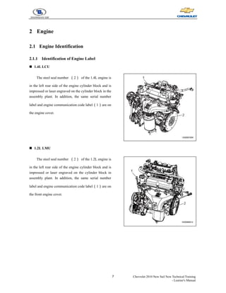
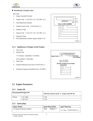
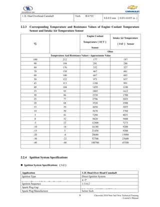
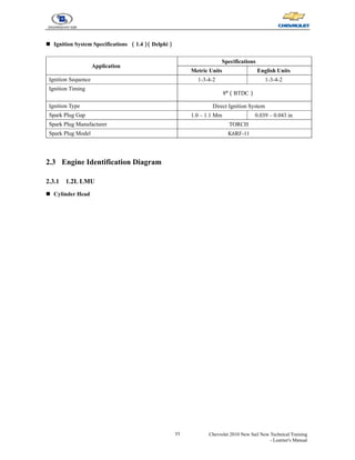
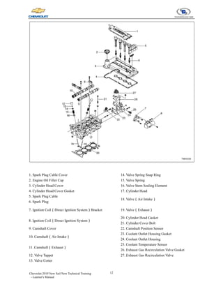
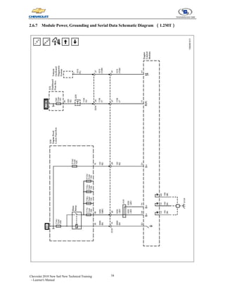
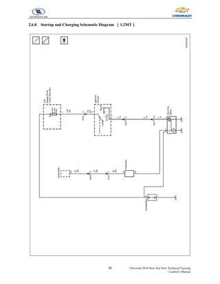
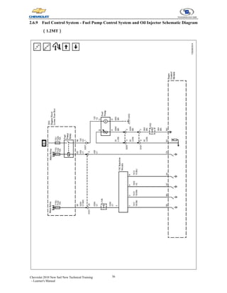
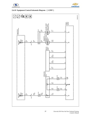
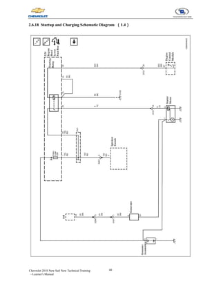
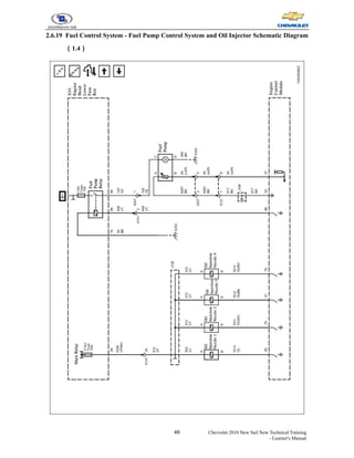
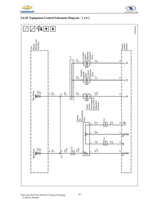
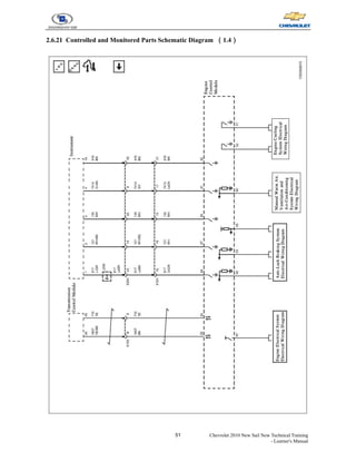
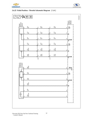
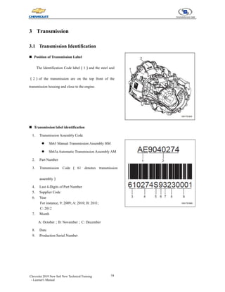
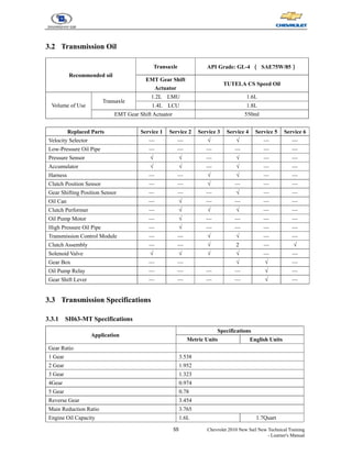
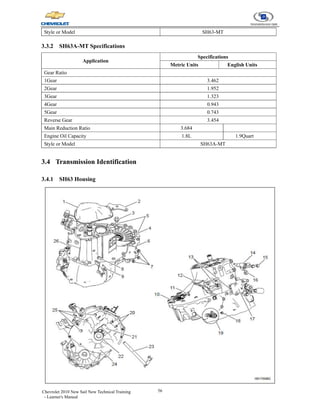
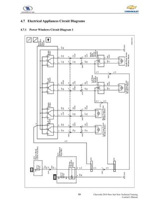
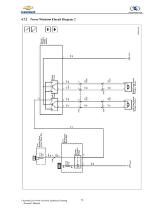
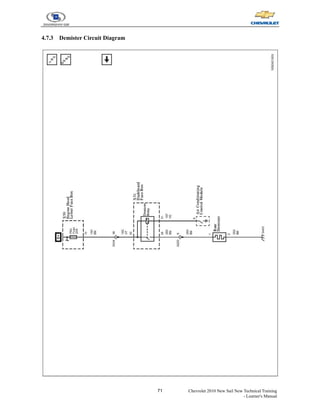
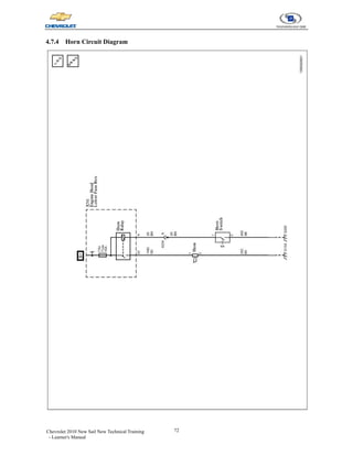
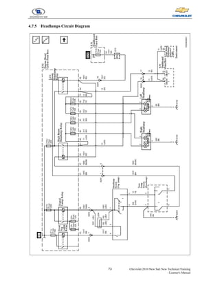
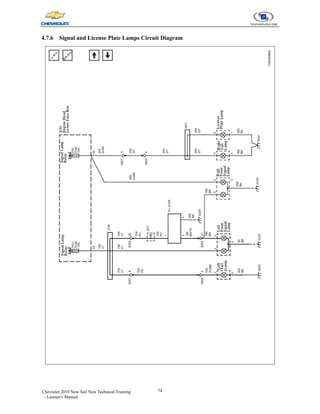
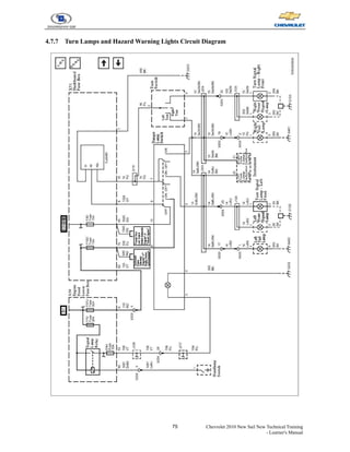
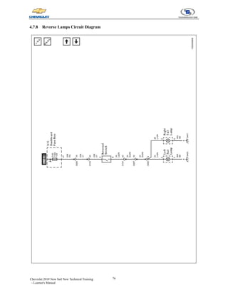
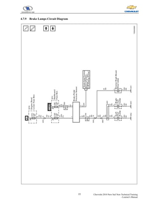
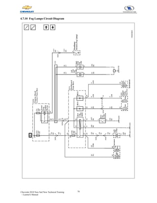
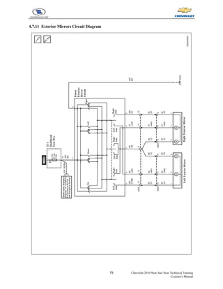
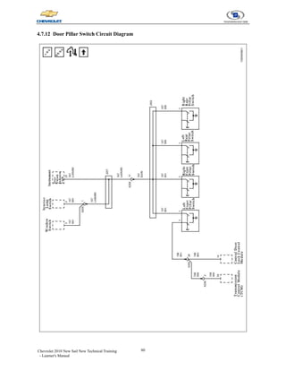
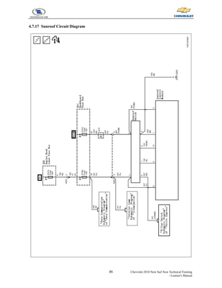
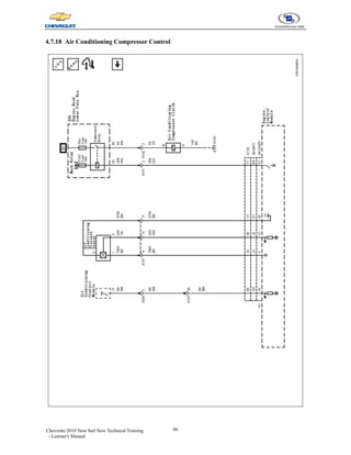
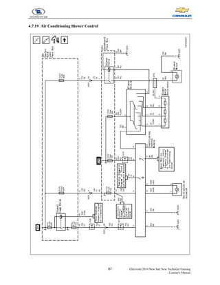
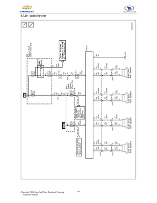
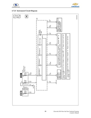
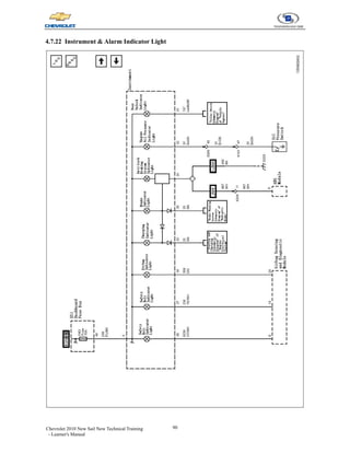
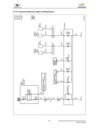
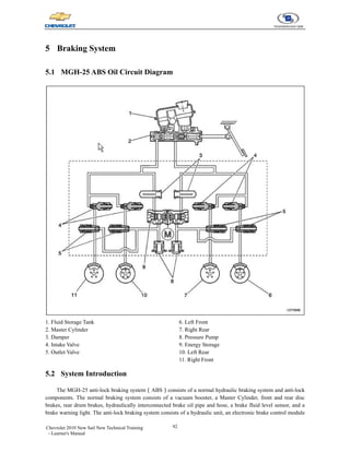
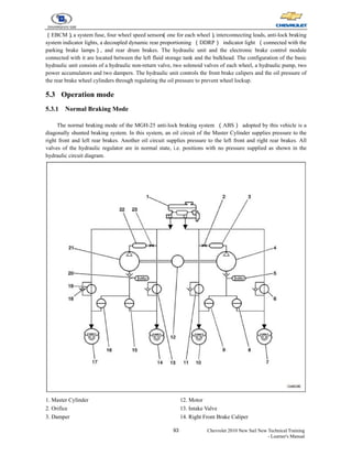
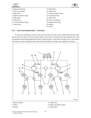
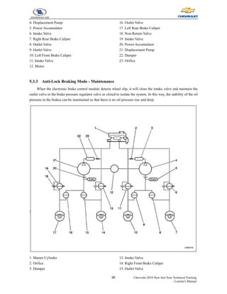
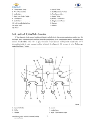
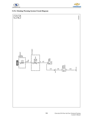
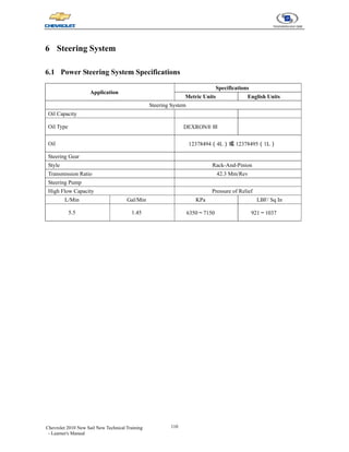
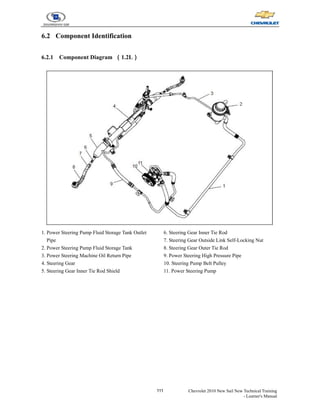
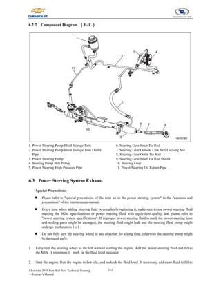
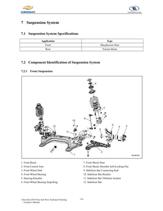
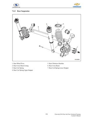
2. Detailed sections cover engine identification and parameters, transmission identification and oil specifications, electrical component diagrams, ABS and braking system operation and diagrams, power steering components, and suspension system specifications.
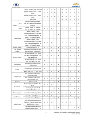
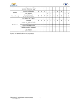
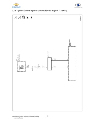
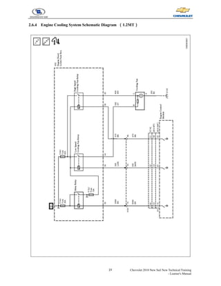
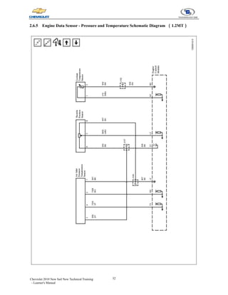
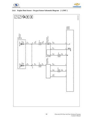
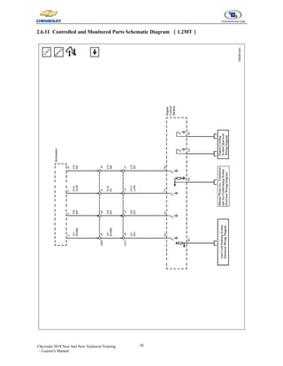
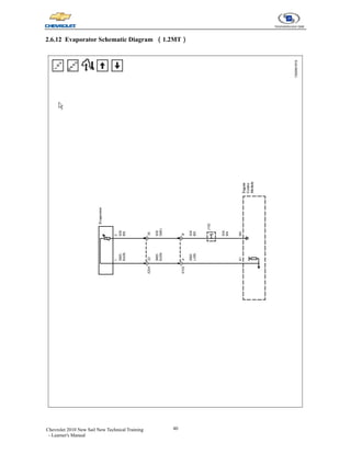
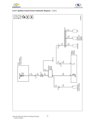
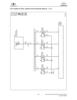
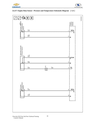
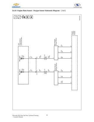
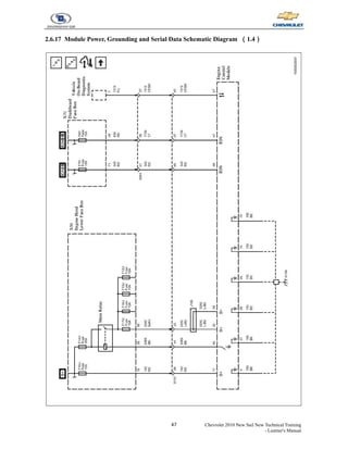
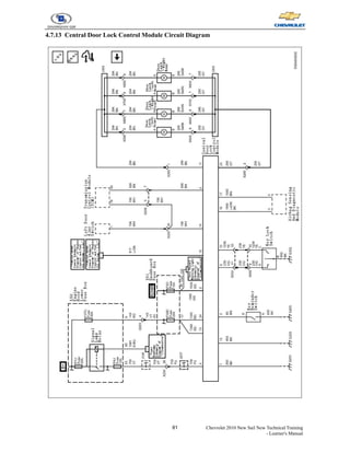
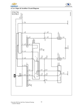
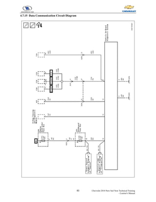
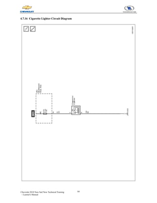
3. Tables and diagrams identify components, circuit diagrams, vehicle options and trim levels to provide technical information and specifications for repairing and maintaining the 2010 Chevrolet Sail.