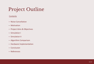
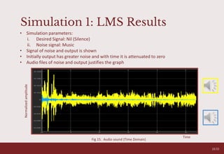
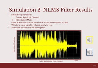
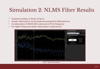
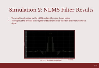
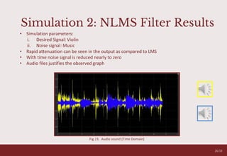
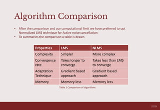
The document discusses the development and implementation of an active noise cancellation (ANC) system aimed at reducing unwanted noise in various environments. It outlines different types of noise cancellation methods, evaluates performance of several algorithms, and highlights the choice of the normalized least mean square (NLMS) algorithm for its real-time processing capabilities. The project concludes with successful hardware implementation of the NLMS algorithm on a DSP board, achieving significant noise attenuation.
![Noise Cancellation
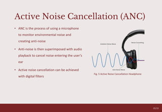
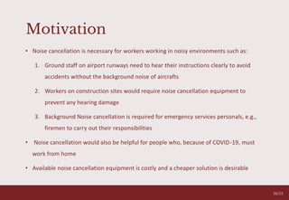
• Noise cancellation is the rejection of
undesired contents in a signal
• There are two main types of noise
cancellation methods
1. Passive Noise Cancellation
2. Active Noise Cancellation Fig. 1 Noise Cancellation [3]
Fig. 3 Passive Noise Cancellation
Fig. 2 Active Noise Cancellation
03/33](https://image.slidesharecdn.com/ancpresentation-210428113321/85/Active-Noise-Cancellation-3-320.jpg)
![Passive Noise Cancellation
• Passive noise cancellation is reduction of
undesired sound using isolating materials
• For instance, headphones reduce noise
based on the physical design of the
earcups
• Some example of isolating materials:
padding insulation, sound absorber tiles
and muffler
Fig. 4 Inside of a Passive Noise Cancellation Ear-cup[4]
04/33](https://image.slidesharecdn.com/ancpresentation-210428113321/85/Active-Noise-Cancellation-4-320.jpg)
![Literature Review (Continued)
O V E R C O M I N G A N X I E T Y T A L K
05
05
O V E R C O M I N G A N X I E T Y T A L K
Feed-forward Control:
• Microphone is placed outside the ear
cup
• Noise signal is detected by microphone
before the person does
• ANC processes the noise and generates
anti-noise signals
• Works well in high frequency ranges
Feed-back Control:
• Microphone is placed inside the ear cup
• Noise signal is detected by microphone
exactly as the listener
• ANC processes the noise and generates anti-
noise signals
• Works well in low frequency ranges
Fig. 6 Feed-back Control Loop [5] Fig. 7 Feed-forward Control Loop [5]
09/33](https://image.slidesharecdn.com/ancpresentation-210428113321/85/Active-Noise-Cancellation-9-320.jpg)
![Literature Review (Continued)
O V E R C O M I N G A N X I E T Y T A L K
05
05
Hybrid Control:
• Using feedback and feedforward
systems
• Reduces error over wider range of
frequencies
• Not prone to sound angles or user wear
Fig. 8 Hybrid Noise Cancellation Control Loop [6]
10/33](https://image.slidesharecdn.com/ancpresentation-210428113321/85/Active-Noise-Cancellation-10-320.jpg)
![Literature Review (Continued)
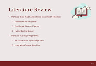
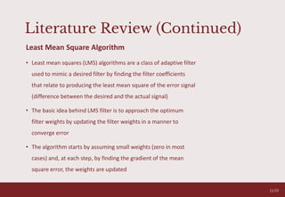
Least Mean Square Algorithm
• LMS is used to calculate weights for the adaptive filter
• Adaptive filter transfer function:
𝑤(𝑛)=
𝑦(𝑛)
𝑥(𝑛)
• Adaptive filter output:
𝑦 𝑛 = 𝑤 𝑛 𝑥(𝑛)
• Error Signal:
𝑒(𝑛) = 𝑑(𝑛) – 𝑦 𝑛 ≈ 𝑠(𝑛)
Where d(n) = 𝑠 𝑛 + 𝑛 𝑛
• 𝑤(𝑛+1) = 𝑤(𝑛) + 𝜇e(n) 𝑥(𝑛)
Where 𝜇 is the converging coefficient
• 𝐸 𝑧2
= 𝐸 𝑠2
+ 𝐸[(𝑛 − 𝑦)2
]
O V E R C O M I N G A N X I E T Y T A L K
05
Fig. 9 Hybrid Noise Cancellation Headphones [1]
12/33](https://image.slidesharecdn.com/ancpresentation-210428113321/85/Active-Noise-Cancellation-12-320.jpg)
![Methodology
O V E R C O M I N G A N X I E T Y T A L K
05
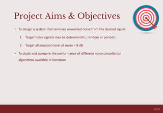
• After the initial literature review of the different methods of
ANC, Hybrid control system is chosen for further investigation
and implementation
• Considering the computational limitations of the processor,
we have decided to adapt the LMS algorithm
• Our system will cancel noise in real-time and work on a Hybrid
(Feedforward + Feedback) loop, taking inputs from two points
in the system (shown in Fig.11)
Fig. 11 Hybrid Noise Cancellation Headphones [7]
14/33](https://image.slidesharecdn.com/ancpresentation-210428113321/85/Active-Noise-Cancellation-14-320.jpg)


![References
[1] P. Lueg, “Process of Silencing Sound Oscillations,” U.S Patent 2043416 Jun. 9, 1936
[2] S. M. Kuo and D. R. Morgan, ”Active Noise Control Systems: Algorithms and DSP
Implementation”. New York: Wiley 1996
[3] A. Swain, “Active Noise Control: Basic Understanding”. Research Gate(2013:1-19)
[4] YPANERN. Available at:
https://www.ypanern.com/index.php?main_page=product_info&products_id=692662
[5] S. Ajay, “Adaptive Active Noise Control” Surge 2007 Programme
[6] P. Sylvia (et al),” Adaptive Feedforward Control for Active Noise Cancellation in-ear
Headphones,” The Journal of the Acoustical Society of America 123(3):2014
[7] XDA-Developers. Available at: https://www.xda-developers.com/razer-opus-
bluetooth-wireless-headphones-active-noise-cancelling
[8] T. Lizhe and J. Jean, “Digital Signal Processing, 3rd ed”, 2019
05
32/33](https://image.slidesharecdn.com/ancpresentation-210428113321/85/Active-Noise-Cancellation-32-320.jpg)