Download to read offline
![IOSR Journal of Electronics and Communication Engineering (IOSR-JECE)
e-ISSN: 2278-2834,p- ISSN: 2278-8735.Volume 7, Issue 1 (Jul. - Aug. 2013), PP 21-27
www.iosrjournals.org
www.iosrjournals.org 21 | Page
Action Trajectory Reconstruction for Controlling of Vehicle
Using Sensors
Vani Prasanna .V1,
P.Srinivasulu2
1
Department of Electronics and Communication Engineering
2
Sri Kalahasteeswara Institute of Technology, Sri kalahasti-517640, India
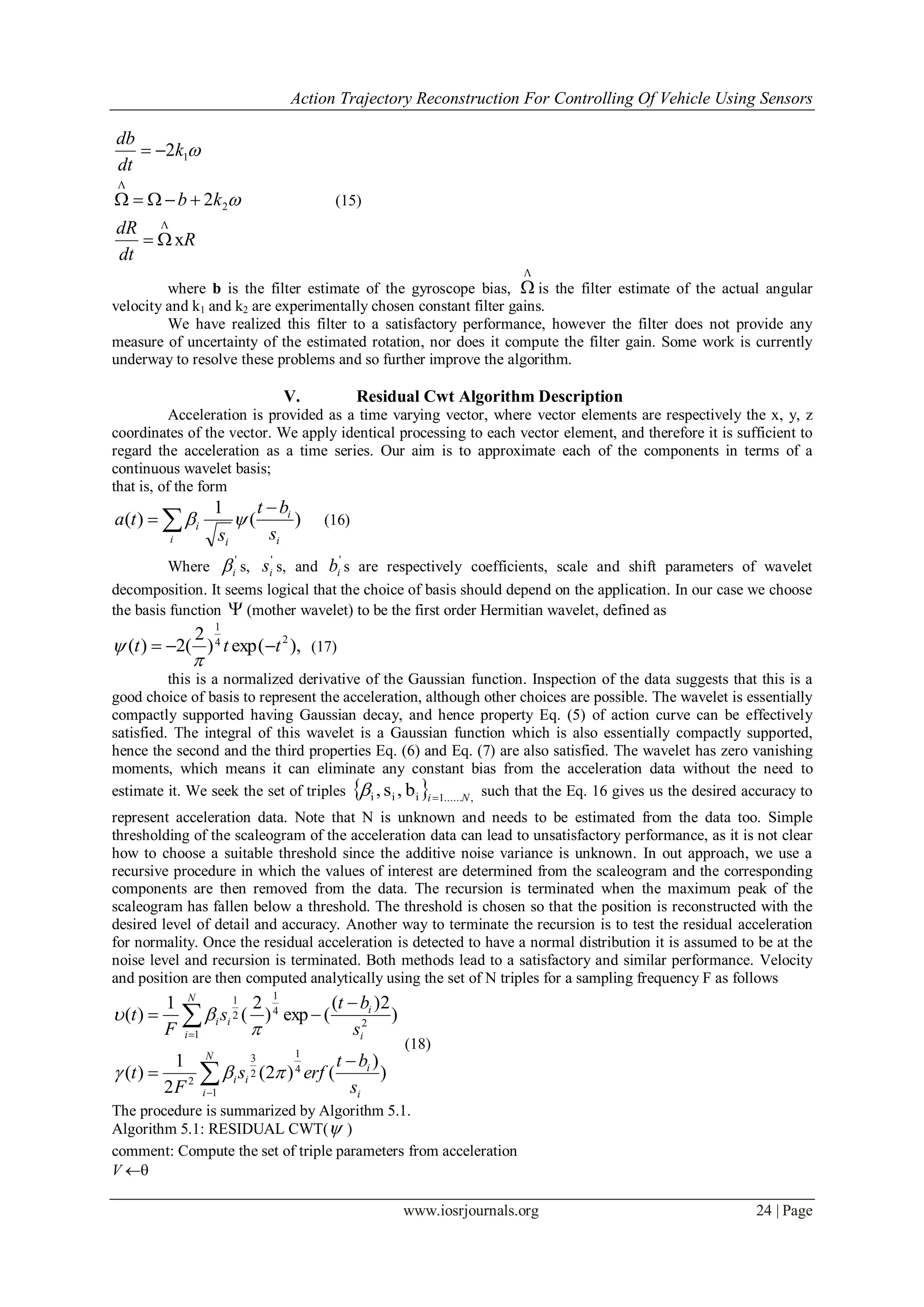
Abstract: Inertial sensors, such as accelerometers and gyro-scopes, are rarely used by themselves to compute
velocity and position as each requires the integration of very noisy data. The variance and bias in the resulting
position and velocity estimates grow un-bounded in time. This paper proposes a solution to provide a de-biased
and de-noised estimation of position and velocity of moving vehicle actions from accelerometer measurements.
The method uses a continuous wavelet transform applied to the measurements recursively to provide reliable
action trajectory reconstruction. The results are presented from experiments performed with a MEMS accele-
rometer and gyroscope.
Keywords: Action trajectory, continuous wavelet transform, inertial measurement unit.
I. Introduction
Inertial sensors are primarily used for navigational purposes, but normally only as one component of a
more complex system. Inertial sensors are typically complemented by GPS, video cameras, infrared, and other
external speed, position and orientation sensors. Measurements are subject to very high noise, time varying bias
and no internal mechanism to correct bias in position or velocity estimates. Recent advances in Micro electro
mechanical systems (MEMS) technology have lead to low cost, small size, lightweight inertial measurement
units (IMU). These advances are now being implemented in sports technology, video games, animation
applications, robotic toys and mini-aerial vehicles. Inertial sensors are often used for orientation and balancing.
The proposed project considers simulating the control of Unmanned Vehicle maneuvering by means of
detecting forearm movements using MEMS accelerometers. A three axis accelerometer is attached to the
forearm and the forearm movements for different controls of the vehicle such as right turn, Left turn, forward
movement and backward movement are detected by the accelerometer in 3-axis and the data is digitized and
processed in the computer using MATLAB Soft-ware. Measurements are subject to very high noise, time
varying bias and no internal mechanism to correct bias in position or velocity estimates. A de-biased and de-
noised estimation of position and velocity of forearm movements from accelerometer measurements are
achieved. The signal processing method uses a continuous wavelet transform applied to the measurements
recursively to provide reliable action trajectory reconstruction.
Raw measurements from the IMUs are supplied in a local and changing frame of reference, where the
transformations between local and global reference frames are unknown, and have to be estimated from repeated
measurement. Several tracking algorithms have been proposed. These estimate orientation. Complementary
tracking on orthogonal groups [5] has been realized to a satisfactory performance, and is used.
In this paper we extend this approach, concentrating on computing the trajectories and velocities given
acceleration measurements. A current approach, referred to as dead (sometimes also ded-for deduced) reckoning
would compute velocity and position by integration and double integration of acceleration measurements.
Unfortunately, the errors between actual and estimated position and velocity can become unbounded with time
[9]. Effectively, the variance of the velocity grows with time as
Nt222
(1)
and the variance of the position as
),12)(1(422
NNNt (2)
Where 2
is the acceleration variance, t is the length of time step and N is the number of time steps.
Acceleration bias is time varying, and is commonly modeled by a slow growing exponential function. The
integration of such bias causes large errors over time. It has been reported that the average displacement error
for Xsens IMU’s after 1 minute is 152 meters [10].
To overcome the bias/noise problems, attempts were made (such as in [11], [12]) not to perform
integration at all, but to use acceleration measurements for the purpose of classification of actions. But this
requires coping with the problem that different rates of movement along the same trajectory result in manifestly
different acceleration measurements. This problem is overcome by the use of arc length (instead of time) to
provide normalization, as arc length allows tracing of action curves with unit speed and permits partial action](https://image.slidesharecdn.com/d0712127-150319050837-conversion-gate01/75/Action-Trajectory-Reconstruction-for-Controlling-of-Vehicle-Using-Sensors-1-2048.jpg)
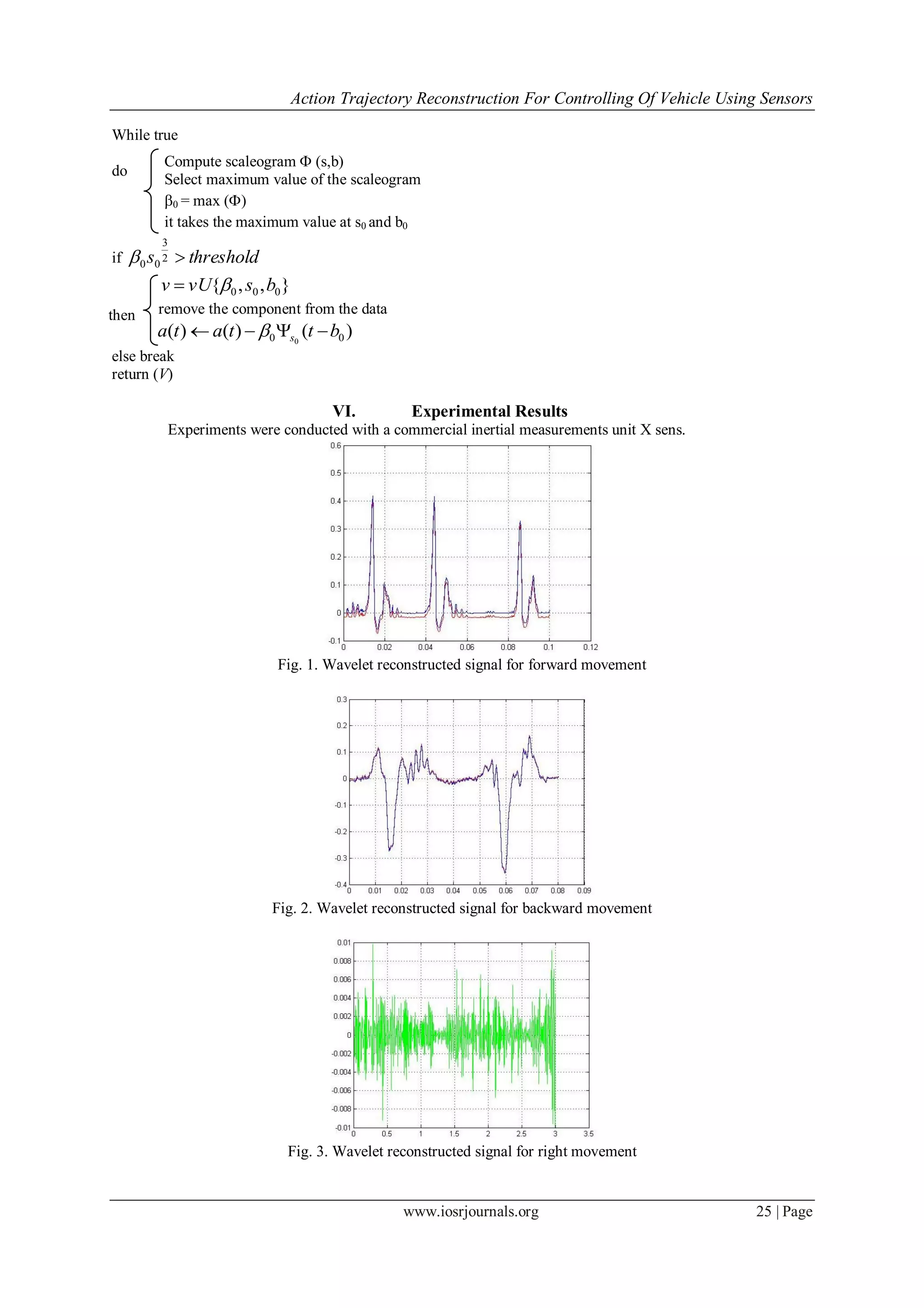
![Action Trajectory Reconstruction For Controlling Of Vehicle Using Sensors
www.iosrjournals.org 22 | Page
recognition. Unfortunately, computation of the arc length requires integration of the data and is therefore subject
to the issues of noise and bias as described above.
Satisfactory trajectories were obtained when IMU’s were complemented by GPS, infrared sensors, or
other position giving sensors [13, 14, 15]. For our application if GPS is used their large current consumption
will drain the battery’s power quickly, limiting the length of acquisition. Use of a larger battery would be
counter to the criteria of small size and unobtrusiveness. Optical sensors (as in the Wii remote) have an
extremely limited volume of space in which the patient can be monitored, and require the patient to remain
constantly within that limited space.
In [16] the periodic motion trajectory was computed using the parameterized model of periodic motion
and the parameters were estimated from acceleration data.
In our approach, the approximate acceleration is obtained in a basis of continuous wavelets. After that, velocity
and position are obtained through analytical integration.
In Section 2 we describe the problem and define action trajectories. In Section 3 we provide a brief
description of continuous wavelet transforms, and the justification for a particular choice of basis that we use.
Section 4 gives a brief description of the complementary tracking filter. Section 5 describes the
estimation algorithm for trajectory reconstruction. The data was collected using a low cost inertial measurement
unit attached to a patient’s wrist. The data was then processed using the algorithm described here. We present
the results in Section 6.
II. Statement of the Problem
The accelerometer measurements can be represented mathematically by the following equation
,)( aaG
T
L bgaRa (3)
Where R is a rotation matrix, representing transformation between local and global frames of reference,
aG is the acceleration vector in the global frame, g is the gravity vector regarded as constant in this context, ba is
an acceleration measurement bias and a is the zero-mean wide-band noise with variance
2
. The rotation
matrix is time dependent and has to be estimated using all measurements from the inertial sensor. We use the
complementary filter from [5] for tracking on the rotation group S0(3). It is defined as
13
)3(
RRRRSO T
(4)
The filter provides an estimation of the rotation matrix and has been realized, and gives a satisfactory
performance. Given R, an estimate of the acceleration aG is computed in a global frame, by the rotation of the
acceleration measurements
And the subtraction of the gravity vector. An action is defined to be a smooth space curve: :
3
21, Rtt such that
0)(:)( 21 tt (5)
0)(:)( 21 tt (6)
],[0)( 21 tttt (7)
That is, at the start time t1 and end time t2 the arm is completely static, and between those times the arm
is in motion. Between t1 and t2 an action curve lies on a manifold and is definable in terms of the constraints
imposed by the arm kinematics.
III. Theory of Continuous Wavelet Transform
In this section we describe the continuous wavelet transform (CWT). A CWT provides a redundant, but
finely detailed, representation of a signal in terms of both time and frequency. CWTs are often used in problems
involving signal identification and the detection of short duration elements of a signal, often hidden in noise.
The CWT is defined by a mother wavelet (t), which has to satisfy a few properties, such as being
absolutely and square integrable, having integral zero and a unit norm. In order to be invertible as a transform it
also has to satisfy the admissibility condition [17]. It is often useful to restrict (t) to be a continuous function
with a number M of vanishing moments such that for all integers m < M
0)( tt
R
m
(8)
This condition in particular allows the “filtering out” of all polynomials of degree < M from the
function f(t).
For a discrete signal f(t), the CWT is computed by correlation of the signal with functions s (t) defined by](https://image.slidesharecdn.com/d0712127-150319050837-conversion-gate01/75/Action-Trajectory-Reconstruction-for-Controlling-of-Vehicle-Using-Sensors-2-2048.jpg)
![Action Trajectory Reconstruction For Controlling Of Vehicle Using Sensors
www.iosrjournals.org 23 | Page
)(
1
)(
s
t
s
ts , (9)
where s > 0 is the scale parameter which deter-mines the width of the wavelet. That is
dt
s
bt
s
tfbs
R
*
1
)(),( (10)
Where * denotes complex conjugation. These correlations are computed for various scales and
assembled as rows of a matrix which is referred to as scaleograms. The scaleogram essentially provides a
measure of similarity between the signal f(t) and the wavelet (t) and its scaled shifted
versions.
IV. Complementary Tracker
Several algorithms are used to estimate the orientation of an IMU. The dead reckoning method
incorporates changes given by the gyroscope to an attitude at the previous epoch. Dead reckoning suffers the
most from the accumulation of errors [10]. Commonly found in current systems is another approach using
extended stochastic linear estimation techniques [6, 7, 8]. However, the Gaussian noise assumptions of such
filters do not apply well, and frequent re initialization is required. The complementary tracker [5] is designed for
tracking on the rotation group, defined in Eq. (4). It finds a mapping from the local frame of the IMU to the
global frame of reference in terms of a rotation Matrix R or equivalently a quaternion. The quaternion
representation of rotations is commonly used for the realization of algorithms on SO(3) because of its continuity
and efficiency in implementation. The set of quaternion's is denoted
1q:xRRs);(qQ 3
(11)
where v = [v1 v2 v3]T
and s are respectively the vectors and the scalar part of the quaternion. The identity
element of the quaternion's is [0 0 0 1]T
. In the methodology the following assumptions are used
ΩxR
dt
dR
hRm
eR
a
a
T
z
T
(12)
where a and m are respectively accelerometer and magnetometer measurements, ez is a unit vector in
the direction of the gravity vector g, i.e. downwards, h is the direction of the magnetic field unit vector and is
the rotation rate vector given by gyroscope measurements. It is assumed that the gravity and magnetic field
vectors are both constant over time. At each epoch the quaternion is initially computed using the accelerometer
and magnetometer measurements via maximum likelihood estimation techniques [18], i.e.
m
T
Rha
T
RgRR
minarg
, (13)
where the weights and represent the confidence in a particular measurement.
Innovation on the rotation group is then computed as follows
)),RR(
2
1
vex(ω
RRR
TΛ
(14)
where vex (W) denotes the inverse of the vector cross product operator, realized by a skew-symmetric
matrix W.
The final estimates for the rotation matrix and gyroscope bias are obtained using the filter innovation and
gyroscope measurements as follows.](https://image.slidesharecdn.com/d0712127-150319050837-conversion-gate01/75/Action-Trajectory-Reconstruction-for-Controlling-of-Vehicle-Using-Sensors-3-2048.jpg)
![Action Trajectory Reconstruction For Controlling Of Vehicle Using Sensors
www.iosrjournals.org 26 | Page
Fig. 4. Wavelet reconstructed signal for left movement
Fig. 5. Wavelet reconstructed signal to stop
Fig. 6. 3D plot for 3-axis MEMS accelerometer
VII. Conclusion
In this paper an algorithm to compute the trajectory of the action from acceleration measurements is
proposed. The problem is posed as an estimation problem and uses continuous wavelet transforms applied to the
data. The estimates are shown to be essentially bias-free, and provide sufficient grounds for subsequent action
recognition and classification. Preliminary experiments were conducted to demonstrate the effectiveness of the
algorithm. The experiments involved simple trajectories, and more experiments with more complex trajectories
are underway. In order to compute errors and statistics, further experiments are conducted and the results will be
reported.
References
[1] Kevin King, S.W. Yoon, N.C. Perkins, K. Najafi, “Wireless MEMS inertial sensor system for golf swing dynamics”, Sensors and
Actuators A: Physical, vol.141,2,2008.
[2] Tapus, Tapus, Mataric, “ Userrobot personality matching and assistive robot behavior adaptation for poststroke rehabilitation
therapy”, Intelligent Service Robotics, vol. 1, issue.2, 2008.
[3] Kelly, Saripalli, Sukhatme, “Combined Visual and Inertial Navigation for an Unmanned Aerial Vehicle,” Field and Service
Robotics, vol.42,2008 @](https://image.slidesharecdn.com/d0712127-150319050837-conversion-gate01/75/Action-Trajectory-Reconstruction-for-Controlling-of-Vehicle-Using-Sensors-6-2048.jpg)
![Action Trajectory Reconstruction For Controlling Of Vehicle Using Sensors
www.iosrjournals.org 27 | Page
[4] Cha, ByungRae. and Jung, YoungKee., “Gesture Recognition Based on Motion Inertial Sensors for Ubiquitous Interactive Game
Contents”, IETE Technical Review, vol. 27, n. 2, 2010
[5] Robert Mahony, Tarek Hamel, Jean-Michel Pflimlin, “Non-linear complementary filters on the special orthogonal group,” IEEE
Transactions on Automatic Control 53, 5, 2008
[6] Angelo M. Sabatini, “Quaternion-Based Extended Kalman Filter for Determining Orientation by Inertial and Magnetic Sensing”,
ieee transactions on biomedical engineering, vol. 53, NO. 7, July 2006.
[7] Zhang, S., Ang, M.H., Xiao, W., Tham, C.K. “Detection of activities for daily life surveillance: Eating and drinking, ” e-health
Networking, Applications and Services. HealthCom 2008. 10th
International Conference on, 2008
[8] Hassen Fourati, Noureddine Manamanni, Lissan Afilal, Yves Handrich, “A Nonlinear Filtering Approach for the Attitude and
Dynamic Body Acceleration Estimation Based on Inertial and Magnetic Sensors: Bio-Logging Application,” ieee sensors journal,
vol. 11,no. 1, Jan. 2011
[9] John H. Wall and David M. Bevly, “Characterization of Inertial Sensor Measurements for Navigation Performance Analysis,”
Proceedings of the 19th Interna-tional Technical Meeting of the Satellite Division of 993 The Institute of Navigation (ION GNSS
2006), Fort Worth, TX, Sep. 2006
[10] Oliver J. Woodman, “An introduction to inertial navigation,” Technical Report Number 696, University of Cambridge, 2007,
http://www.cl.cam.ac.uk/techreports/](https://image.slidesharecdn.com/d0712127-150319050837-conversion-gate01/75/Action-Trajectory-Reconstruction-for-Controlling-of-Vehicle-Using-Sensors-7-2048.jpg)

The paper presents an algorithm for reconstructing vehicle action trajectories using data from inertial sensors like accelerometers and gyroscopes, addressing issues of noise and bias in measurements. It employs a continuous wavelet transform for effective estimation of position and velocity, thus enabling reliable control of unmanned vehicles based on detected forearm movements. Experimental results demonstrate the algorithm's effectiveness in generating accurate action trajectories for various vehicle maneuvers.


![Sensor Fusion Study - Real World 2: GPS & INS Fusion [Stella Seoyeon Yang]](https://cdn.slidesharecdn.com/ss_thumbnails/gpsins-200817095309-thumbnail.jpg?width=640&height=640&fit=bounds)


