More Related Content
Similar to Presentation for the 21th EUROSTAR Users Conference - June 2013
Similar to Presentation for the 21th EUROSTAR Users Conference - June 2013 (20)
Presentation for the 21th EUROSTAR Users Conference - June 2013
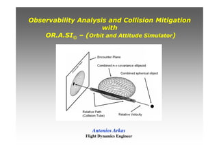
- 1. Observability Analysis and Collision Mitigation
with
OR.A.SI© – (Orbit and Attitude Simulator)
Antonios Arkas
Flight Dynamics Engineer
- 2. 1. Condition Number, Observability
and
Orbit Determination Error Variance
Observability Analysis and Collision Mitigation with
OR.A.SI© (Orbit and Attitude Simulator)
- 3. What is the most appropriate setup for orbit determination ?
(Setup ↔ Model : Specific combination of measurement types with solve-for parameters)
Criteria for Quality of Orbit Determination
1. Conditioning : Low sensitivity of the model to antenna noise and
bias uncertainties.
2. Observability : Uniqueness of estimation for all parameters of the state vector.
1,...mi =+= iii xHy ε
rrr
Model : Linearized observation-state relationship for usual least square method
- Observation parameter deviation vector
x
r
- Solve-for parameters deviation vector
m - Number of observations
- ith observation error
( )oi
i
i tt
X
G
H ,Φ⋅
∂
∂
=
( ) iiii tXGY ε
rrr
+= , Nonlinear observation-state expression and ( )oi tt ,Φ the transition matrix
iy
r
iε
r
1.1 Quality of Orbit Determination
Observability Analysis and Collision Mitigation with
OR.A.SI© (Orbit and Attitude Simulator)
- 4. 1.2 Conditioning and Observability (1/2)
Measurement Model Condition Number κp(Η)
Measure of relative sensitivity of the solve-for parameters x to relative errors in measurement
matrix H and measurement noise ε.
Facts
Sensitivity to measurement noise is proportional to κ2.
The higher the value of κ2 the more close to singularity is measurement
matrix H (Relevance to Theoretical Observability).
Number of significant digits lost during inversion of H is grosely log10(κ2(H))
(Relevance to Numerical Observability).
Observability Analysis and Collision Mitigation with
OR.A.SI© (Orbit and Attitude Simulator)
For l2-norm : and
si – singular values of H
and( )
p
p
p
p
p
y
H
x
x ε
κ
δ
⋅≤ ( )
p
p
p
p
p
H
H
H
x
x δ
κ
δ
⋅≤
∑=
=
n
i
ixx
1
2
2
2
2
1
2 max x
Ax
A
x
= =
- 5. 1.2 Conditioning and Observability (2/2)
Theoretical Observability of the Model y = Ηx + ε
Ability to apply the estimator to a particular system (measurement model) and obtain a unique
estimate for all solve-for parameters. This is equivalent to:
The rank of the m x n matrix H must be n (m > n).
H must have n nonzero singular values (Singular Value Decomposition).
The determinant of HTH must be greater than zero.
Measurement NoiseNumerical Error in forming
and inverting normal equations
(Numerical Observability)
Sources of error in the estimated state (Solution of the normal equations)
- Solution of normal equations
- Actual state
Numerical observability may be different from the theoretical one.
Any solution with loss of precision log10(κ2) greater than half the total
floating point precision digits (machine ε), should be highly suspect.
Observability Analysis and Collision Mitigation with
OR.A.SI© (Orbit and Attitude Simulator)
- 6. 1.2 Observability Analysis Module Characteristics (1/2)
Module Initialization (Orbit Determination Simulator)
Production of range, and tracking measurements with identically independently
distributed (iid) errors εi for whatever type of orbit and any number of Earth stations in
the relevant coverage.
Gaussian noise distribution εi with desired mean value E(εi) (systematic error) and
variance E(εΤ
i εi) = σ2
i.
Configuration of different measurement plan for each ground station with suitable
choice of the following parameters :
Type of acquired measurements.
Error variance.
Time offset of the first localization session.
Time offset between sessions.
Time offset between range and tracking measurements.
Number of sessions.
Antenna bias uncertainties for calculation of consider covariance.
Output epoch for propagation of covariance matrices.
Maneuver characteristics (Epoch , DV, relative error) following orbit determination, for
calculation of propagated covariance matrices.
Observability Analysis and Collision Mitigation with
OR.A.SI© (Orbit and Attitude Simulator)
- 7. 1.2 Observability Analysis Module Characteristics (2/2)
κ2 condition number and rank of HTR-1H normal equations matrix.
Warning for ill-conditioned matrices.
Propagated noise only and consider a posteriori covariance matrices of the Cartesian and
Keplerian state vector forms and the model parameters with respect to the ECI (Earth Centered
Inertial) reference frame.
Propagated noise only and consider a posteriori covariance matrices of the Cartesian state
vector form with respect to the local satellite reference frame RTN (R-Radial, T-Along Track, N-
Cross Track).
Confidence ellipsoid characteristics (semi axes lengths and orientation/Euler angles) with respect
to local satellite reference frame.
Module Output
κ2 condition number and rank of the scaled information matrix:
• R= E[εiεi
T ] - Matrix of the measurement covariance.
• R-1/2 - Square root of R = R-T/2 R-1/2
• D - State scaling diagonal nxn matrix with elements
the l2 norm of the corresponding column of
R-1/2 H, that is Di = ||(R-1/2 H):i||2
Observability Analysis and Collision Mitigation with
OR.A.SI© (Orbit and Attitude Simulator)
- 8. 1.3 Observability Dependence on Geometry & Orbit Determination Setup
Antenna Longitude [deg East] Latitude [deg] Range Noise (1-σ) [m] Azimuth Noise (1-σ) [deg] Elevation Noise (1-σ) [deg]
THP2 22.6859 38.8224 4 0.002 0.002
CYP 33.3843 34.8592 4 0.002 0.002
• Same type of measurements have the same noise for both antennas.
• Antenna biases for both antennas have no uncertainties.
• 24 Sessions with 2h between range measurements and 10 min between range and tracking measurements.
• Geosynchronous spacecraft at 390 East.
Noise Only Standard Deviations [m] Scaled Measurement Matrix
Case Setup of Measurements Solve-For Parameters R- 1σ T - 1σ N - 1σ Condition Rank
Single Antenna Measurements
1 THP2 (Rg+Az+El) THP2 (Az+El) + Cp 37.3 110.9 348.0 4.81e2 9
2 CYP (Rg+Az+El) CYP (Az+El) + Cp 36.6 704.75 352.4 3.27e3 9
Double Ranging
3 THP2 (Rg) + CYP (Rg) CYP (Rg) + Cp 18.9 80.67 177.1 5.25e2 8
4 THP2 (Rg) + CYP (Rg) THP2 (Rg) + Cp 18.9 265.5 177.1 1.76e3 8
Double Ranging and Tracking from One Antenna
5 THP2 (Rg+Az+El) + CYP (Rg) THP2 (Az+El) +CYP (Rg) + Cp 17.02 79.7 158.0 5.18e2 10
6 THP2 (Rg+Az+El) + CYP (Rg) THP2 (Rg+Az+El) + Cp 17.02 263.8 158.0 1.74e3 10
Range and Tracking from Both Antennas
7 THP2 (Rg+Az+El) + CYP (Rg+Az+El) CYP (Rg) + Cp 15.26 63.1 143.8 4.1e2 8
8 THP2 (Rg+Az+El) + CYP (Rg+Az+El) THP2 (Rg) + Cp 15.9 109.7 143.5 7.14e2 8
9 THP2 (Rg+Az+El) + CYP (Rg+Az+El) CYP (Rg) + THP2 (Az+El) + Cp 15.4 68.0 143.9 4.4e2 10
10 THP2 (Rg+Az+El) + CYP (Rg+Az+El) THP2 (Rg) + CYP (Az+El) + Cp 15.0 149.9 143.6 9.85e2 10
11 THP2 (Rg+Az+El) + CYP (Rg+Az+El) CYP (Rg+Az+El) + THP2 (Az+El) + Cp 15.6 78.4 144.2 5.12e2 12
12 THP2 (Rg+Az+El) + CYP (Rg+Az+El) CYP (Az+El) + THP2 (Rg+Az+El) + Cp 15.6 261.8 144.1 1.73e3 12
Observability Analysis and Collision Mitigation with
OR.A.SI© (Orbit and Attitude Simulator)
- 9. Along track standard deviation with respect to the condition number
0 500 1000 1500 2000 2500 3000 3500
0
100
200
300
400
500
600
700
800
AlongTrack1-σduetoMeasurementNoise[m]
Along Track Standard Deviation
Polynomial Fit with Second Order Polynomial
Condition of Scaled Measurement Matrix κ2
Observability Analysis and Collision Mitigation with
OR.A.SI© (Orbit and Attitude Simulator)
- 10. Along track standard deviation with respect to loss of significant digits
Singular Value Decomposition (SVD) precision based on log10(κ2) underestimates
the actual loss of precision as the matrix approaches singularity.
3 4 5 6
0
100
200
300
400
500
600
700
800
AlongTrack1-σduetoMeasurementNoise[m]
Along Track Standard Deviation
log10
(κ2
) (Loss of Significant Digits)
Actual loss of significance
SVD Precision
Underestimation
Observability Analysis and Collision Mitigation with
OR.A.SI© (Orbit and Attitude Simulator)
- 11. • 24 Sessions with 2h between range measurements and 10 min between range and tracking measurements.
• Geosynchronous spacecraft at 390 East.
1.4 Observability, Consider Covariance & Quality of Orbit Determination (1/2)
Antenna
Longitude
[deg East]
Latitude
[deg]
Range Noise
(1-σ) [m]
Azimuth Noise
(1-σ) [deg]
Elevation Noise
(1-σ) [deg]
Range Bias Uncertainty
(1-σ) [m]
Azimuth Bias Uncertainty
(1-σ) [deg]
Elevation Bias Uncertainty
(1-σ) [deg]
THP2 22.6859 38.8224 4.23 0.003 0.0017 11.4 0.0015 0.0015
CYP 33.3843 34.8592 3.4 0.0147 0.0112 5 0.0025 0.0025
Noise Only Standard Deviations [m] Consider Analysis Standard Deviations [m] Scaled Measurement Matrix
Case Setup of Measurements Solve-For Parameters R- 1σ T - 1σ N - 1σ R- 1σ T - 1σ N - 1σ Condition Rank
Single Antenna Measurements
1 THP2 (Rg+Az+El) THP2 (Az+El) + Cp 34.7 110.6 323.6 34.7 327.1 323.6 4.5e2 9
2 CYP (Rg+Az+El) CYP (Az+El) + Cp 198.6 743.8 2021.4 198.5 825.2 2021.5 3.7e3 9
Double Ranging
3 THP2 (Rg) + CYP (Rg) CYP (Rg) + Cp 18.1 81.5 169.4 18.1 318.4 169.4 5.7e2 8
4 THP2 (Rg) + CYP (Rg) THP2 (Rg) + Cp 18.1 268.5 169.4 18.1 449.4 169.4 1.9e3 8
Double Ranging and Tracking from One Antenna
5 THP2 (Rg+Az+El) + CYP (Rg) THP2 (Az+El) +CYP (Rg) + Cp 16.2 80.4 150.1 16.2 318.12 150.1 5.6e2 10
6 THP2 (Rg+Az+El) + CYP (Rg) THP2 (Rg+Az+El) + Cp 16.1 267.5 150.1 16.1 448.9 150.1 1.9e3 10
Range and Tracking from Both Antennas
7 THP2 (Rg+Az+El) + CYP (Rg+Az+El) CYP (Rg) + Cp 16.0 75.3 149.6 17 298.4 150.7 5.3e2 8
8 THP2 (Rg+Az+El) + CYP (Rg+Az+El) THP2 (Rg) + Cp 15.6 182.0 149.2 17.8 453.7 151.44 1.3e3 8
9 THP2 (Rg+Az+El) + CYP (Rg+Az+El) CYP (Rg) + THP2 (Az+El) + Cp 16.1 80.1 149.7 16.1 316.5 149.7 5.6e2 10
10 THP2 (Rg+Az+El) + CYP (Rg+Az+El) THP2 (Rg) + CYP (Az+El) + Cp 15.6 184.35 149.2 17.9 464.7 151.5 1.3e3 10
11 THP2 (Rg+Az+El) + CYP (Rg+Az+El) CYP (Rg+Az+El) + THP2 (Az+El) + Cp 16.1 80.4 149.7 16.1 318.1 149.7 5.7e2 12
12 THP2 (Rg+Az+El) + CYP (Rg+Az+El) CYP (Az+El) + THP2 (Rg+Az+El) + Cp 16.1 267.3 149.7 16.1 448.8 149.7 1.9e3 12
Observability Analysis and Collision Mitigation with
OR.A.SI© (Orbit and Attitude Simulator)
- 12. 1.4 Observability, Consider Covariance & Quality of Orbit Determination (2/2)
Observability primarily depends on the geometry of the Earth stations participating in
the localization campaign and the orbit determination setup.
Since observability is directly connected to the variance of the along track error, the
Flight Dynamics Engineer can detect the best possible orbit determination setup by
comparing the aforementioned variance corresponding to each different setup.
Observability can’t guarantee best orbit determination performance due to the
additional error dispersion introduced by the uncertainty of the consider parameters.
Conclusions
2,6 2,8 3,0 3,2 3,4 3,6 3,8 4,0 4,2 4,4 4,6 4,8 5,0
0
200
400
600
800
AlongTrack1-σduetoMeasurementNoise[m]
Actual loss of
significance
log10
(κ2
) (Loss of Significant Digits)
Along Track Standard Deviation
SVD Precision
Underestimation
0 500 1000 1500 2000 2500 3000 3500 4000
0
100
200
300
400
500
600
700
800
AlongTrack1-σduetoMeasurementNoise[m]
Condition of Scaled Measurement Matrix κ2
Along Track Standard Deviation
Second Order Polynomial Fit
Equation
y = Intercept +
B1*x^1 + B2*x^
2
Weight No Weighting
Residual Sum
of Squares
1641,0144
Adj. R-Square 0,99487
Value Standard Error
Along Track St Intercept 53,69291 11,0751
Along Track St B1 0,03935 0,01504
Along Track St B2 3,97067E-5 3,82244E-6
Observability Analysis and Collision Mitigation with
OR.A.SI© (Orbit and Attitude Simulator)
- 13. 1.5 Difference Between Theoretical and Numerical Observability
Even when the state vector x is theoretically observable from a given set of measurements,
numerical errors may cause observability tests to fail. Conversely, numerical errors may also
allow observability tests to pass when the system is theoretically unobservable.
Solution Flooding From Numerical Errors in an ill-conditioned setup
Scenario : Acquisition of 2 days range and tracking measurements from
single station THP2 and setting all antenna biases as solve-for
parameters along with the state vector.
- Solution of normal equations
- Actual state
Numerical Error in forming
and inverting normal equations
(Numerical Observability)
Along Track 1-σ : 25.5 km
Correction of Range Bias : 2 km
Radial 1-σ : 34.7 m Cross Track 1-σ : 324 m
Condition Number : 1.3e5
Observability Analysis and Collision Mitigation with
OR.A.SI© (Orbit and Attitude Simulator)
- 14. 1.6 Validation of Formal Consider Covariance with Monte Carlo (1/2)
Linearized observation-state relationship for consider covariance method
1,...mi =++= icxi cHxHy ii
ε
rr
c
r
- Consider parameter deviation vector
Let W the weighting matrix, P the covariance matrix of the usual least square method
and C the a priori covariance matrix of the consider parameter.
( )( )( )TT
x
T
cc
T
x
c
WPHCHHWPHPP +=Consider Covariance Matrix
Validation Scenario - Both Range and Tracking Measurements from Two Antennas
Antenna
Longitude
[deg East]
Latitude
[deg]
Range Noise
(1-σ) [m]
Azimuth Noise
(1-σ) [deg]
Elevation Noise
(1-σ) [deg]
Range Bias Uncertainty
(1-σ) [m]
Azimuth Bias Uncertainty
(1-σ) [deg]
Elevation Bias Uncertainty
(1-σ) [deg]
THP2 22.6859 38.8224 5.0 0.0023 0.00124 6.0 0.0015 0.0015
CYP 33.3843 34.8592 5.0 0.0129 0.0137 5.0 0.002 0.002
• Geosynchronous spacecraft at 390 East.
• Acquisition of range and tracking measurements from both stations.
• 24 sessions with 2h between range measurements and 10 min between range and tracking measurements.
• Solve-for parameters: State vector – Reflectivity Coefficient Cp – Range Bias for THP2 – Azimuth and
Elevation biases for both antennas.
Observability Analysis and Collision Mitigation with
OR.A.SI© (Orbit and Attitude Simulator)
- 15. 1.6 Validation of Formal Consider Covariance with Monte Carlo (2/2)
Solve-for Antenna Bias Standard Deviations
THP2 Antenna CYP Antenna
R- 1σ T - 1σ N - 1σ Range Bias Azimuth Bias Elevation Bias Azimuth Bias Elevation Bias
[m] [deg]
Formal Computation 17.649 486.787 161.495 16.16 0.001108 0.000363 0.002722 0.002611
Monte Carlo 17.869 487.866 162.529 16.17 0.001104 0.000357 0.002743 0.002598
Number of Monte Carlo Iterations: 3000
0 500 1000 1500 2000 2500 3000
14
16
18
20
22
24
26
Radial1-σ[m]
Number of Monte Carlo Iterations
Sigma DR
Convergence of Radial 1-σ
0 500 1000 1500 2000 2500 3000
450
500
550
600
650
700
750
800
AlongTrack1-σ[m]
Number of Monte Carlo Iterations
Sigma DT
Convergence of Along Track 1-σ
Consider covariance matrix is absolutely necessary not only for observability
analysis but also for the assessment of collision probability.
0 500 1000 1500 2000 2500 3000
150
160
170
180
190
200
CrossTrack1-σ[m]
Number of Monte Carlo Iterations
Sigma DN
Convergence of Cross Track 1-σ
Observability Analysis and Collision Mitigation with
OR.A.SI© (Orbit and Attitude Simulator)
- 16. 2. Close Approach Detection
Observability Analysis and Collision Mitigation with
OR.A.SI© (Orbit and Attitude Simulator)
- 17. Utilization as a standard propagator with either impulsive or continuous maneuver
execution.
Choice between three different integrators:
4th Order Runge-Kutta-Fehelberg RKF4(5) adaptive step size.
8th Order Runge-Kutta Dormant-Prince 853 adaptive step size.
mth Order Adams-Moulton fixed step size.
Ephemeris and orbital plots for each propagated spacecraft.
Inter-satellite ephemeris and orbital plots for each pair of propagated spacecrafts.
Inter-satellite calculations for collocated spacecrafts.
Inter-satellite distance evolution.
Eccentricity and inclination separation evolution.
Evolution of angle between eccentricity-inclination vectors.
Evolution of geocentric angle between spacecrafts.
Preliminary detection of close approach (accuracy depended on ephemeris step size)
Detection of multiple consecutive close approach encounters .
State vector of each spacecraft on close approach.
Relative position of the spacecrafts on close approach.
2.1 Multiple Satellite Propagation and Close Approach Module Characteristics
Observability Analysis and Collision Mitigation with
OR.A.SI© (Orbit and Attitude Simulator)
- 18. 2.2 Multiple Satellite Propagation and Close Approach Module Interface
Observability Analysis and Collision Mitigation with
OR.A.SI© (Orbit and Attitude Simulator)
- 19. Raduga 9 Incident: Detection of Intrusion Dates with Sub-Satellite Longitude Graphs
Observability Analysis and Collision Mitigation with
OR.A.SI© (Orbit and Attitude Simulator)
- 20. Raduga 9 Incident: Detection of Consecutive Close Encounters with Inter-satellite Distance Graphs
Observability Analysis and Collision Mitigation with
OR.A.SI© (Orbit and Attitude Simulator)
- 21. Raduga 9 Incident : Close Approach Details for 10 sec detection step
Observability Analysis and Collision Mitigation with
OR.A.SI© (Orbit and Attitude Simulator)
- 22. Observability Analysis and Collision Mitigation with
OR.A.SI© (Orbit and Attitude Simulator)
Raduga 9 Incident: Long Term Prediction of Next Close Approach
- 23. 3. Collision Mitigation for
High Relative Velocity Encounters
Observability Analysis and Collision Mitigation with
OR.A.SI© (Orbit and Attitude Simulator)
- 24. All figure were borrowed from AIAA Paper 05-308 COLLISION AVOIDANCE MANEUVER PLANNING TOOL
by SALVATORE ALFANO
3.1 Geometry and Mathematics of High Relative Velocity Close Encounters (1/2)
Assumptions
Small encounter time to
ensure constancy of the
individual covariance
matrices and the resulting
combined covariance
matrix.
High relative velocity to
allow the reduction of the
3D integral to a 2D one.
Observability Analysis and Collision Mitigation with
OR.A.SI© (Orbit and Attitude Simulator)
- 25. 3.1 Geometry and Mathematics of High Relative Velocity Close Encounters (2/2)
Maximum probability Pmax corresponds
to xm=0 and a specific minor semi axis of
combined covariance ellipse.
The probability dilution region is that
region where the standard deviation of
the combined covariance minor semi
axis σx exceeds that which yield Pmax.
If operating within the dilution region,
then the further into this region the
uncertainty progresses the more
unreasonable it becomes to associate low
probability with low risk.
Two-dimensional probability equation in the encounter plane: • OBJ - Combined object radius.
• σx - Projected covariance ellipse
minor semi axis.
• σy - Projected covariance ellipse
major semi axis.
• (xm ,ym) - Projection of miss distance
on covariance frame.
Observability Analysis and Collision Mitigation with
OR.A.SI© (Orbit and Attitude Simulator)
- 26. 3.2 Collision Mitigation Module Characteristics
Accurate calculation of close approach characteristics (depended on detection step size):
Miss distance on TCA (Time of Closest Approach).
Relative position and velocity of secondary object with respect to primary object
on TCA.
State vector details of both primary and secondary objects on TCA.
Collision probability assessment.
Collision probability based on combined covariance.
Maximum collision probability for unfavorable orientation and size of the
combined covariance ellipsoid.
Calculation of probability dilution region.
Characteristics of the combined error ellipsoid and its projection on the conjunction
plane (combined covariance ellipse)
Design and optimality testing of along track (East-West) avoidance maneuvers for a
desired range of DVs.
Collision probability following the execution of each avoidance maneuver .
Miss distance following the execution of each avoidance maneuver
Longitude window violation details corresponding to desired avoidance maneuver.
Monte Carlo simulation of spacecraft collision with or without avoidance maneuver.
Observability Analysis and Collision Mitigation with
OR.A.SI© (Orbit and Attitude Simulator)
- 27. 3.3 Collision Mitigation Module Interface
Observability Analysis and Collision Mitigation with
OR.A.SI© (Orbit and Attitude Simulator)
- 28. 3.4 Validation of Miss Distance and Relative Position -Velocity Calculations
Observability Analysis and Collision Mitigation with
OR.A.SI© (Orbit and Attitude Simulator)
- 30. Combined Covariance Ellipse Characteristics
Observability Analysis and Collision Mitigation with
OR.A.SI© (Orbit and Attitude Simulator)
- 31. 3.5 Why Probability Calculations are Much Safer than Miss Distance for
Collision Mitigation Decision Making (1/2)
Close Approach Scenario for Miss Distance 1.166 Km and P = 5E-08
Miss Distance – Relative Position – Relative Velocity – Collision Probability
Observability Analysis and Collision Mitigation with
OR.A.SI© (Orbit and Attitude Simulator)
- 32. 3.5 Why Probability Calculations are Much Safer than Miss Distance for
Collision Mitigation Decision Making (2/2)
Dependence of collision probability on relative position of spacecraft line of sight, on TCA, with respect to combined covariance ellipse
Observability Analysis and Collision Mitigation with
OR.A.SI© (Orbit and Attitude Simulator)
- 33. 3.6 Validation for Collision Probability P = 0.0164 in the Dilution Region (1/2)
Close Approach Scenario
Miss Distance – Relative Position – Relative Velocity – Collision Probability
Observability Analysis and Collision Mitigation with
OR.A.SI© (Orbit and Attitude Simulator)
- 34. 0 20000 40000 60000 80000 100000 120000
0,010
0,012
0,014
0,016
0,018
0,020
CollisionProbability
Number of Monte Carlo Iterations
Collision Probability
Monte Carlo Convergence of Collision Probability
• Theoretical : 0.01645
• Monte Carlo : 0.01639 (121846 iterations)
3.6 Validation for Collision Probability P = 0.0164 in the Dilution Region (2/2)
Observability Analysis and Collision Mitigation with
OR.A.SI© (Orbit and Attitude Simulator)
- 35. What is the latest time with respect to
TCA when a moderate (~ 0.04 m/s)
avoidance maneuver is able to
substantially decrease the collision
probability ?
Observability Analysis and Collision Mitigation with
OR.A.SI© (Orbit and Attitude Simulator)
- 36. 3.7 Avoidance Maneuver Calculation (1/2)
Close Approach Scenario for P = 1.925E-02 in Probability Dilution Region
Miss Distance – Relative Position – Relative Velocity – Collision Probability
Observability Analysis and Collision Mitigation with
OR.A.SI© (Orbit and Attitude Simulator)
- 37. Miss Distance versus Along Track DV and Centroid
Observability Analysis and Collision Mitigation with
OR.A.SI© (Orbit and Attitude Simulator)
- 38. Collision Probability versus Along Track DV and Centroid
Observability Analysis and Collision Mitigation with
OR.A.SI© (Orbit and Attitude Simulator)
- 39. 3.8 Validation of Collision Mitigation with an Avoidance Maneuver
Collision Probability without Avoidance Maneuver : 1.93E-02
• Theoretical : 1.95E-06 (Probability Dilution)
• Monte Carlo : 2.5E-06 (2 million iterations)
Collision Probability with a 0.04 m/s maneuver 2h prior to TCA
Observability Analysis and Collision Mitigation with
OR.A.SI© (Orbit and Attitude Simulator)
- 40. How much does the collision probability
depend on state covariance matrix
norm ?
or else
How strong does the collision probability
depend on observability ?
or else
Can a specific choice of orbit
determination setup reduce the
collision probability ?
Observability Analysis and Collision Mitigation with
OR.A.SI© (Orbit and Attitude Simulator)
- 41. 3.9 Collision Probability and Observability
Collision probability can be substantially decreased by selecting the orbit
determination setup characterized from the best observability with respect to all
the possible allowable setups.
Best case primary
object’s state
covariance
Worst case primary
object’s state
covariance
Best case state covariance (Best Observability)
Worst case state covariance (Worst Observability)
Observability Analysis and Collision Mitigation with
OR.A.SI© (Orbit and Attitude Simulator)
- 42. Best case state
covariance
Dependence of Combined Covariance Ellipsoid Size on Individual Covariance Ellipsoids
Miss Distance : 1.166 Km
Worst case state
covariance
Observability Analysis and Collision Mitigation with
OR.A.SI© (Orbit and Attitude Simulator)
- 43. 4. Run-Time for
Close Approach Calculations
Observability Analysis and Collision Mitigation with
OR.A.SI© (Orbit and Attitude Simulator)
- 44. Observability Analysis and Collision Mitigation with
OR.A.SI© (Orbit and Attitude Simulator)
4.1 Characteristic Run-Time for Close Approach Calculations
Machine Used for OR.A.SI© Execution : Laptop with Intel i7 Processor and 2GB RAM
Preliminary Detection of Close Approach with Multiple Satellite Propagation
and Close Approach Module
• Detection period : 20 days
• Ephemeris Time Step : 1 min
• Propagator : 8th order Adams-Moulton
Run-Time: 22 sec
Accurate Detection of Close Approach with Collision Mitigation Module
• Detection Time Step : 0.01 sec
• Propagator : 8th order Adams-Moulton
Run-Time: 6 sec
Avoidance Maneuver Calculation with Collision Mitigation Module
• Detection Time Step : 0.01 sec
• Number of Different Maneuver DV’s : 10
• Number of Centroids for Each DV : 20
• Total Avoidance Maneuver Number : 200
• Propagator : 8th order Adams-Moulton
Run-Time: 3 min 33sec
- 45. 5. Future Plans for Further
Investigations & Development
Observability Analysis and Collision Mitigation with
OR.A.SI© (Orbit and Attitude Simulator)
- 46. 5.1 Future Plans for Further Investigations & Development (1/2)
Theoretical investigation on the feasibility of incorporating consider parameter
uncertainties in the condition number of the scaled measurement matrix to reflect
their impact on observability.
Development of code for calculation of collision probability for nonlinear low velocity
relative motion, appropriate for encounters of collocated GEO spacecrafts.
Increase of the time span and accuracy of preliminary detection for close approach
events with utilization of adaptive detection step size.
Incorporation of cross track (North-South) avoidance maneuver calculation in
collision mitigation module.
More extensive validation of collision probability module computations with Monte
Carlo simulations.
Elaboration on the difference between the actual collision probability and the
theoretical one in cases of probability dilution.
Automatic collision avoidance maneuver calculation for collocated spacecrafts.
Observability Analysis and Collision Mitigation with
OR.A.SI© (Orbit and Attitude Simulator)
- 47. Addition of maneuver increments as sole-for parameters in orbit determination
module.
Computation of inclination control maneuvers with the optimized long term control
strategy.
Description of a realistic model for the atmosphere up to the height of 1000 Km in
order to take account the air drug perturbation for LEO calculations (Jacchia
model).
Orbit determination based on Kalman filter sequential estimator.
5.1 Future Plans for Further Investigations & Development (2/2)
Observability Analysis and Collision Mitigation with
OR.A.SI© (Orbit and Attitude Simulator)