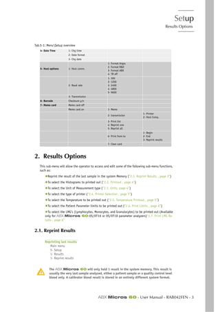
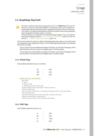
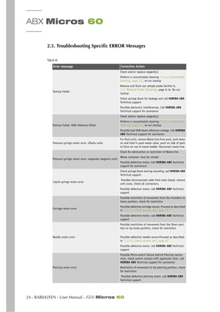
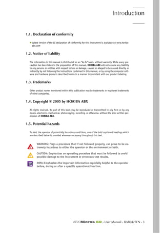
The ABX Micros 60 is a fully automated hematology analyzer that performs complete blood count (CBC) testing on whole blood samples. The main components and features include:
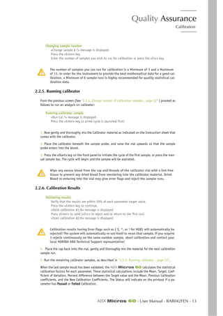
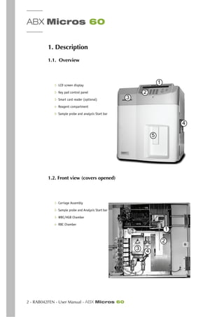
1. Electrical supply: Provides power to the instrument.
2. Electronic main board: Contains the microprocessor and electronics that control the operation of the instrument.
3. Dilution pneumatics: System that handles sample dilution and aspiration.
4. Control panel: Includes a keypad and LCD screen for operator input and output display.
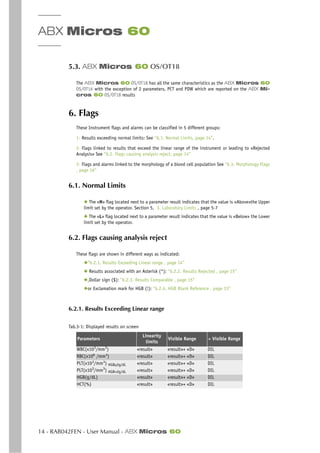
5. Reagent compartment: Houses reagents used in sample testing and analysis.
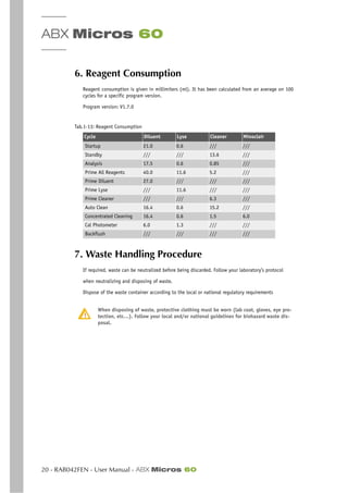
6. Printer: Prints out test results, distribution curves, and other output.
7. Optional
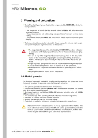
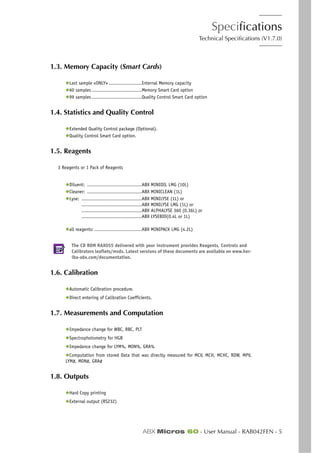
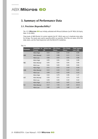
![Specifications
Limitations
ABX Micros 60 - User Manual - RAB042FEN - 15
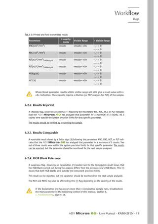
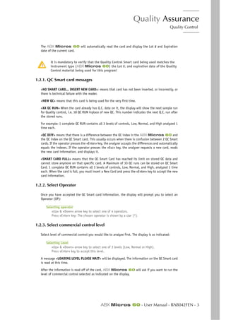
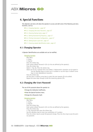
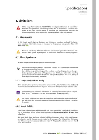
Agglutinated Red Blood cells - May cause a falsely low RBC count. Blood samples containing the
agglutinated Red blood cells may be identified by observing abnormal MCH and MCHC values, as well
as examination of a stained blood smear.
Cold Agglutinins - IgM Immunoglobulins which are elevated in Cold Agglutinins disease, may lower
RBC and PLT counts and increase the MCV.
4.3.3. WBC White Blood Cells (Leukocytes)
WBC results that exceed the linearity limits of the system will require a Dilution of the blood sample.
Re-assaying the diluted blood sample will help to obtain the correct assay value. As in some Leuke-
mia patients.
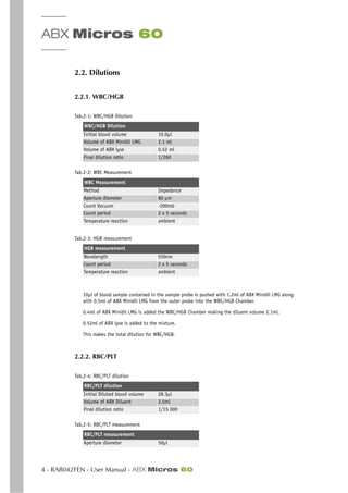
NRBC - Immature (Nucleated Red Blood Cells) will be counted in the WBC (White Blood Cell) param-
eter. If the number of Nucleated Red Blood cells is sufficient enough to activate an «L1 Alarm», such
interference will be detected. However, a Manual differential white blood cell count, performed on
a stained blood smear, will confirm the presence of NRBC’s.
When NRBC’s are present in the WBC count, the formula for correcting the WBC parameter is as
followed:
Corrected WBC = (Counted WBC’s x 100) / [100 + (# of NRBC’s/100 WBC)]
Non-lysed Red Cells - In particularly rare instances, the erythrocytes in the blood sample may not
completely lyse when lysing reagent is added in the WBC Chamber. These non-lysed Red blood cells
may be detected on the WBC Histogram with an «L1 Alarm» or as an elevated baseline on the (Left
leading edge) of the Lymphocytes population in the WBC Histogram. Non-lysed erythrocytes will also
cause a falsely elevated WBC count.
Following the Manual differential white blood cell count, the WBC assay value «Must be corrected to
subtract the NRBC’s from the total white blood cell count. This will give a true and correct count of
the actual WBC’s.
Multiple Myeloma - The precipitation of proteins in Multiple Myeloma patients may give elevated
WBC counts.
Hemolysis - Hemolyzed specimens contain Red cell Stroma which may elevate WBC counts.
Leukemia - A very low WBC count may result in this disease state because of possible increased
fragility of the leukocytes leading to some destruction of these cells during counting. These white
cell fragments will also interfere with the white cell partial differential parameters: LYM % and #,
MON % and #, GRA % and #. A suspiciously low WBC count may also be seen in patients with Lym-
phocytic Leukemias due to the presence of abnormally «Small» lymphocytes which may not be
counted by the instrument.
Chemotherapy - Cytotoxins and Immunosuppressive drugs may increase the fragility of the leuko-
cytes which may cause low WBC counts.
Cryoglobulins - Increased levels of Cryoglobulins that may be associated with Myeloma, Carcinoma,
Leukemia, Macroglobulineima, Lymphoproliferative disorders, Mestastic turmors, Auto-immune dis-
orders, Infections, Idiopathic disease, Aneurism, Pregnancy, Thromboembolic phenomena, Diabetes,
.......etc, which can elevate the WBC, RBC, and PLT counts along with the HGB value. The specimen
can be warmed up to 37O
C and re-analyzed immediately. If warming the specimen has no effect on
the count, a Manual WBC, RBC,and or PLT count can be performed.
Increased Turbidity - may also be seen in cases where the red blood cells are resistant to the lysing
action. This condition will cause a falsely elevated Hemoglobin result, but may be detected by ob-
serving the abnormal MCH and MCHC values, also the increased baseline on the (Left leading edge)
of the WBC histogram. Erroneous Hemoglobin results will also cause the results of the MCH and MCHC
to be erroneous as well.](https://image.slidesharecdn.com/abxmicros60-manual-150908155818-lva1-app6891/85/Abx-micros-60-manual-31-320.jpg)
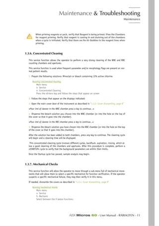
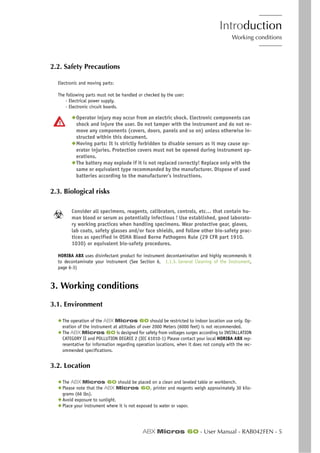
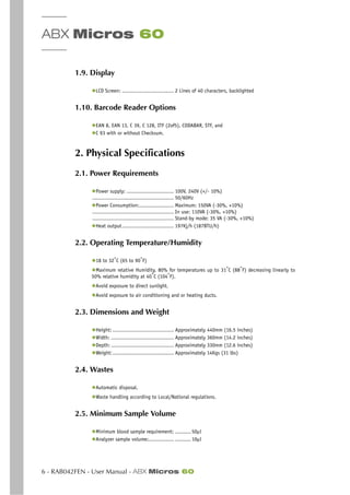
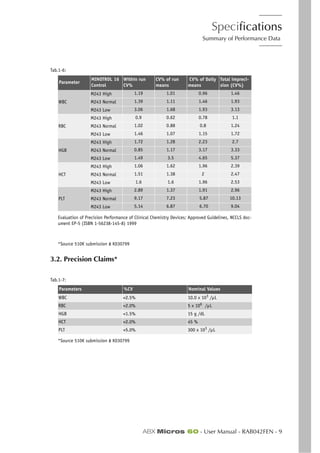
![Description & Technology
Technology
ABX Micros 60 - User Manual - RAB042FEN - 7
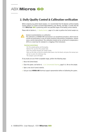
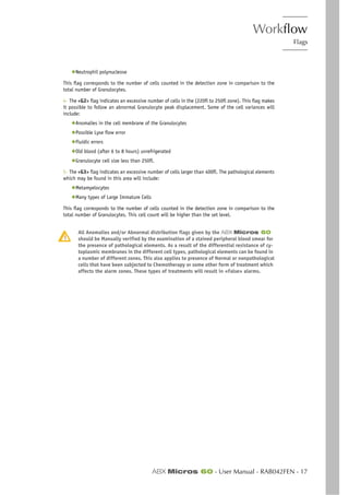
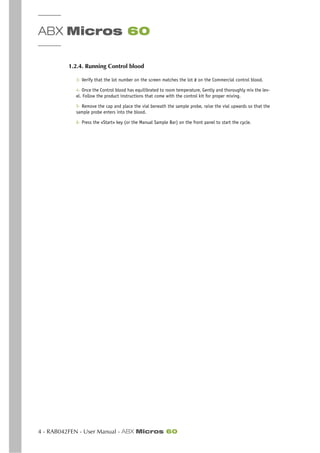
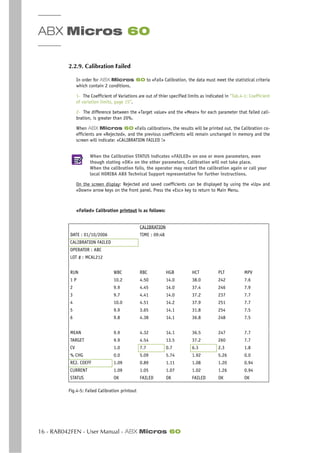
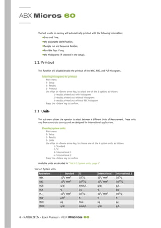
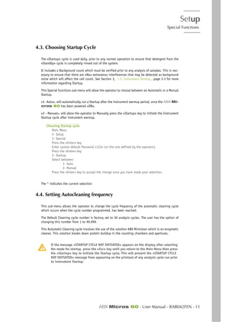
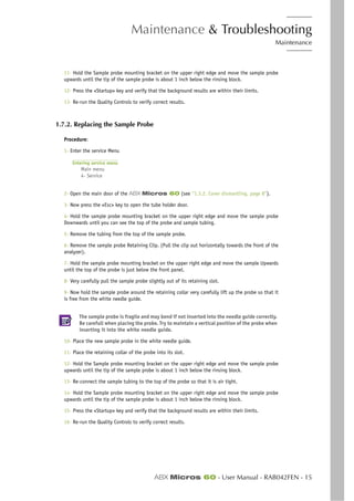
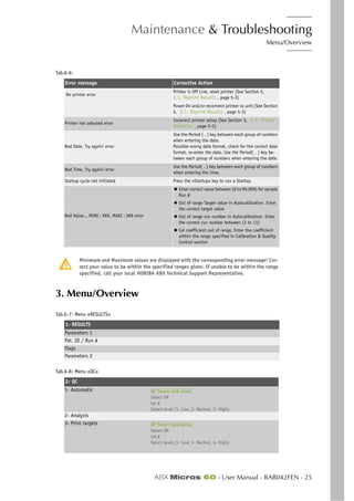
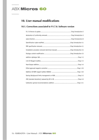
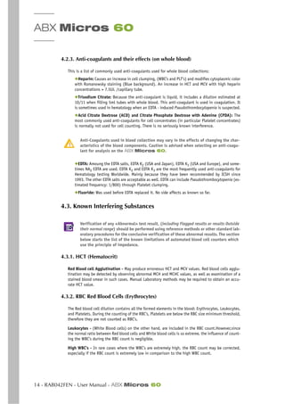
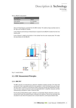
Fig.2-4: RBC Pulses electronically calculated and smoothed: RBC Distribution curve
Fig.2-5: PLT pulses electronically calculated and smoothed: PLT distribution curve
RBC Histogram: is an electronic Distribution and mathematical calculation of the RBC’s placed into
256 Channels of volumetric sizing from 30fl to 300fl.
PLT Histogram: is an electronic distribution and mathematical calculation of the PLT’s placed into
128 channels of volumetric sizing from 2fl to a mobile threshold between the high end platelets to
the Low end Red Blood Cell Thresholds.
(fl = fentaliters) A microscopic volumetric unit of measurement. This is a 3-dimentional measurement
used to determine the volume of Microscopic particles.
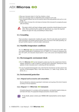
2.3.2. HGB
The Hemoglobin measurement is based on a Startup cycle. This cycle includes a Hemoglobin Blank
test sequence which includes 2 Hemoglobin blank measurements. Each analysis cycle run after Start-
up also has a Hgb Blank measurement which is compared to the initial Start-up Hgb Blank. Each
analysis cycle run thereafter compares the Hgb Blank reading to the previous cycle Hgb Blank read-
ing.
During the WBC analysis cycle, 0.52ml of Lyse Reagent is added to 2.05ml of diluted blood in the
WBC Chamber. The Lyse reagent contains potassium ferricyanide [Fe(Cn)]K, and potassium cyanide
[KCN]. This lysing reagent breaks down the RBC Cell membrane and releases the Hemoglobin within
the RBC.
The Hemoglobin then combines with the potassium cyanide to form a chromogenous cyanmethemo-
globin compound. This chemical compound is measured by Spectrophotometry, through the optical
pathway in the WBC chamber. The light wavelength of measurement is at 550nm.
HGB using ABX Lysebio : Reagent for erythrocyte lysis and cyanide-free determination of hemoglo-
bin. All the heme iron is oxidized and stabilized producing chromogenic species for quantitation by
spectrophotometry at a wavelength of 550nm.
Results, The Hgb results are given as such:
HGB = Log(blank value/Sample value) x the Calibration Coefficient.
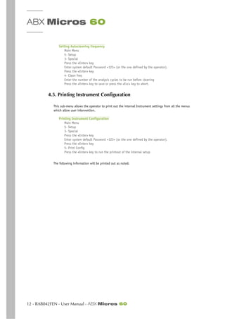
Number of cells
Cell size
Number of cells
Cell size](https://image.slidesharecdn.com/abxmicros60-manual-150908155818-lva1-app6891/85/Abx-micros-60-manual-43-320.jpg)