Download to read offline

![International Research Journal of Engineering and Technology (IRJET) e-ISSN: 2395 -0056
Volume: 03 Issue: 01 | Jan-2016 www.irjet.net p-ISSN: 2395-0072
© 2016, IRJET | Impact Factor value: 4.45 | ISO 9001:2008 Certified Journal | Page 1278
machine. Thus, by implementation of this model efficiency
is increased. Complete system is automatic. The accident
cases also reduce.
REFERENCES
[1] Kendesarin Pimraksa, Matthias Wilhelm and Michael
kochhberger,” A New Approach to the Production of
Bricks Made of 100% Fly Ash, International Ash
Utilization Symposium, University of Kentucky, 2001.
[2] Obada Kayali, “High Performance Bricks From Fly
Ash”lecture notes, Lexington, Kentucky,USA, 2005.
[3] Ankit H Parmar, Kinnarraj P Zala, Ankit R Patel,
“Modification of Foremost Element of Hydraulic Press
Machine”, IJASTR,vol. 3, june 2014.
[4] A. Sumathi, K. Saravana Raja Mohan, “Compressive
Strength of Fly Ash Brick with Addition of Lime,
Gypsum and Quarry Dust”, IJCRGG, Vol. 7, pp 28-36,
2014-2016.
[5] Cockrell, L. Sander, T.M. Holnan Inc., Dundee, MI.,”
Process control in cement industry”, IEEE
Transaction, vol-28, pp: 945 – 953, 2006.
[6] Prime, J.B. Valdes, J.G, “use of ladder diagram in
discrete system of PLC,” IEEE Transaction, vol. PAS-
100, pp- 143 – 153, January 1989.
[7] N.Gangadhar Reddy,” High Capacity Fly Ash Bricks &
Blocks Unit, “A project report, May 2014.
[8] Ravi Masand, Prof. S.P Shukla,” PLC and SCADA based
Fault Diagnosis of Induction Motor”, IJDACR, Vol. 2,
January 2001.
[9] A.K. Swain,August, “Material mix control in cement
plant automation”, IEEE, vol. 4, pp. 24-27, 2009.](https://image.slidesharecdn.com/irjet-v3i1222-171023061035/85/A-Review-Paper-on-PLC-Based-Automatic-Fly-Ash-Brick-Machine-5-320.jpg)

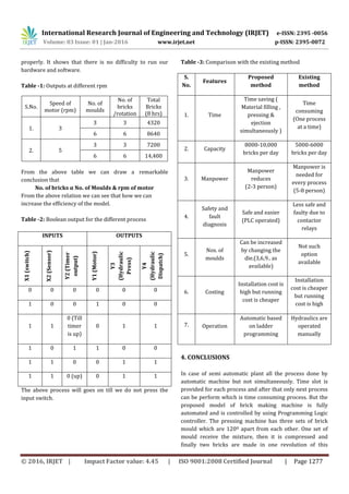
This document summarizes a research paper on developing an automatic fly ash brick machine using a programmable logic controller (PLC). The machine uses a hydraulic press mechanism to mold bricks from a fly ash mixture. Key aspects include: 1. The machine has a circular table with three molds spaced 120 degrees apart. As the table rotates, each mold receives mixture, is compressed into bricks by hydraulics, and the finished bricks are ejected. 2. An infrared sensor detects when a mold is in position to stop the table motor. A timer then activates the hydraulic press and ejector for a set duration to form each pair of bricks. 3. The process is fully automated through a PLC