This document reviews the increasing integration of grid-connected photovoltaic (GCPV) systems into the utility grid, highlighting advancements in inverter technology, standards for safe operation, and the challenges that arise from their proliferation, such as grid stress and management of variable generation. It discusses efficiency improvements through technologies like maximum power point tracking and ancillary services support by inverters, while also addressing market trends and future grid parity with conventional energy sources. Overall, the paper underscores the critical role of GCPVs in renewable energy strategies and the need for strategic solutions to ensure reliable grid performance.
![International Journal of Trend in Scientific Research and Development, Volume 1(4), ISSN: 2456-6470 www.ijtsrd.com
558
IJTSRD | May-Jun 2017
Available Online @www.ijtsrd.com
A Review on Grid-Connected PV System
Anjali
M.Tech Scholar, Electrical Engineering Department
R.P. Inderaprastha Institute of Technology, Karnal
Gourav Sharma
Assis Professor, Electrical Engineering Department
R.P. Inderaprastha Institute of Technology, Karnal
ABSTRACT
The concept of injecting photovoltaic power into the
utility grid has earned widespread acceptance in these
days of renewable energy generation & distribution.
Grid-connected inverters have evolved significantly
with high diversity. Efficiency, size, weight,
reliability etc. have all improved significantly with the
development of modern and innovative inverter
configurations and these factors have influenced the
cost of producing inverters.
This paper presents a literature review of the recent
technological developments and trends in the Grid-
Connected Photovoltaic Systems (GCPVS). In
countries with high penetration of Distributed
Generation (DG) resources, GCPVS have been shown
to cause unwanted stress on the electrical grid. A
review of the existing and future standards that
addresses the technical challenges associated with the
growing number of GCPVS is presented. Maximum
Power Point Tracking (MPPT), Solar Tracking (ST)
and the use of transform-less inverters can all lead to
high efficiency gains of Photovoltaic (PV) systems
while ensuring minimal interference with the grid.
Inverters that support ancillary services like reactive
power control, frequency regulation and energy
storage are critical for mitigating the challenges
caused by the growing adoption of GCPVS.
Keywords: Grid connected power system,
Photovoltaic System, Maximum Power Point
Tracking System, style, Solar Tracking, Totla
Harmonic Distortions
I. INTRODUCTION
Renewable energy is increasingly considered essential
for meeting current and future energy needs [1].
Photovoltaic (PV) power, as it is clean and unlimited
source of energy, is probably the best technology
amongst all renewable energy sources and therefore a
considerable amount of research has been conducted
recently in this field. To better utilize the PV power,
grid interconnection of PV system is needed. PV
power rendering to the utility grid has been the fastest
growing renewable energy technology by far since it
attracted the attention of policy makers [2].
It is generally accepted in the scientific community
that human activity is affecting climate change and
that a majority of this impact comes from fossil fuel
combustion caused by the electric utility industry. In
2012, 32% of the total greenhouse gas emissions in
the U.S. was from the electric power industry, the
highest of all sectors. Conventional fossil-fuel
generating facilities have in past met the majority of
global electrical energy demands. However,
environmental and climate change implications of
fossil fuel-based generation present serious challenges
to society and the environment. Distributed
Generation (DG), particularly Photovoltaic (PV)
systems, provides a means of mitigating these
challenges by generating electricity directly from
sunlight. Unlike off-grid PV systems, Grid-Connected
Photovoltaic Systems (GCPVS) operate in parallel
with the electric utility grid and as a result they
require no storage systems. Since GCPVS supply
power back to the grid when producing excess
electricity (i.e., when generated power is greater than
the local load demand), GCPVS help offset
greenhouse gas emissions by displacing the power
needed by the connected (local) load and providing
additional electricity to the grid. As such, during peak
solar hours (maximum solar irradiance), fewer
conventional generation plants are needed. In
addition, GCPVS reduce Transmission and
Distribution (T&D) losses. Although average T&D
losses amounted to 5.7% in the U.S. in 2010, losses
during peak hours are higher [3]. For example, the
estimated T&D losses for Southern California Edison
and Pacific Gas & Electric exceeded 10% in 2010 [4].](https://image.slidesharecdn.com/81areviewongrid-connectedpvsystem-180808041545/85/A-Review-on-Grid-Connected-PV-System-1-320.jpg)
![International Journal of Trend in Scientific Research and Development, Volume 1(4), ISSN: 2456-6470 www.ijtsrd.com
558
IJTSRD | May-Jun 2017
Available Online @www.ijtsrd.com
A Review on Grid-Connected PV System
Anjali
M.Tech Scholar, Electrical Engineering Department
R.P. Inderaprastha Institute of Technology, Karnal
Gourav Sharma
Assis Professor, Electrical Engineering Department
R.P. Inderaprastha Institute of Technology, Karnal
ABSTRACT
The concept of injecting photovoltaic power into the
utility grid has earned widespread acceptance in these
days of renewable energy generation & distribution.
Grid-connected inverters have evolved significantly
with high diversity. Efficiency, size, weight,
reliability etc. have all improved significantly with the
development of modern and innovative inverter
configurations and these factors have influenced the
cost of producing inverters.
This paper presents a literature review of the recent
technological developments and trends in the Grid-
Connected Photovoltaic Systems (GCPVS). In
countries with high penetration of Distributed
Generation (DG) resources, GCPVS have been shown
to cause unwanted stress on the electrical grid. A
review of the existing and future standards that
addresses the technical challenges associated with the
growing number of GCPVS is presented. Maximum
Power Point Tracking (MPPT), Solar Tracking (ST)
and the use of transform-less inverters can all lead to
high efficiency gains of Photovoltaic (PV) systems
while ensuring minimal interference with the grid.
Inverters that support ancillary services like reactive
power control, frequency regulation and energy
storage are critical for mitigating the challenges
caused by the growing adoption of GCPVS.
Keywords: Grid connected power system,
Photovoltaic System, Maximum Power Point
Tracking System, style, Solar Tracking, Totla
Harmonic Distortions
I. INTRODUCTION
Renewable energy is increasingly considered essential
for meeting current and future energy needs [1].
Photovoltaic (PV) power, as it is clean and unlimited
source of energy, is probably the best technology
amongst all renewable energy sources and therefore a
considerable amount of research has been conducted
recently in this field. To better utilize the PV power,
grid interconnection of PV system is needed. PV
power rendering to the utility grid has been the fastest
growing renewable energy technology by far since it
attracted the attention of policy makers [2].
It is generally accepted in the scientific community
that human activity is affecting climate change and
that a majority of this impact comes from fossil fuel
combustion caused by the electric utility industry. In
2012, 32% of the total greenhouse gas emissions in
the U.S. was from the electric power industry, the
highest of all sectors. Conventional fossil-fuel
generating facilities have in past met the majority of
global electrical energy demands. However,
environmental and climate change implications of
fossil fuel-based generation present serious challenges
to society and the environment. Distributed
Generation (DG), particularly Photovoltaic (PV)
systems, provides a means of mitigating these
challenges by generating electricity directly from
sunlight. Unlike off-grid PV systems, Grid-Connected
Photovoltaic Systems (GCPVS) operate in parallel
with the electric utility grid and as a result they
require no storage systems. Since GCPVS supply
power back to the grid when producing excess
electricity (i.e., when generated power is greater than
the local load demand), GCPVS help offset
greenhouse gas emissions by displacing the power
needed by the connected (local) load and providing
additional electricity to the grid. As such, during peak
solar hours (maximum solar irradiance), fewer
conventional generation plants are needed. In
addition, GCPVS reduce Transmission and
Distribution (T&D) losses. Although average T&D
losses amounted to 5.7% in the U.S. in 2010, losses
during peak hours are higher [3]. For example, the
estimated T&D losses for Southern California Edison
and Pacific Gas & Electric exceeded 10% in 2010 [4].](https://image.slidesharecdn.com/81areviewongrid-connectedpvsystem-180808041545/75/A-Review-on-Grid-Connected-PV-System-1-2048.jpg)
![International Journal of Trend in Scientific Research and Development, Volume 1(4), ISSN: 2456-6470 www.ijtsrd.com
559
IJTSRD | May-Jun 2017
Available Online @www.ijtsrd.com
Locating DG assets close to loads can help to partially
mitigate these losses.
In this paper, we focus our attention on the growing
adoption of GCPVS and the technical challenges
posed by the mass proliferation of these DG systems
on the overall performance and reliability of the
electric grid. A review of the standards governing the
safe installation, operation and maintenance of
GCPVS, and the known methods of improving
efficiency of PV systems are presented. Some
transformer-less topologies based on half-bridge, full-
bridge configuration and multilevel concept, and
some soft-switching inverter topologies are remarked
as desirable for grid-connected single-phase PV
inverters with respect to high efficiency, low cost, and
compact structure. We also focus on the role of the
inverter as an active grid participant. Inverters
designed with the ability to support electric grid
ancillary services will become the norm in the
foreseeable future, especially in light of the growing
number of small and large-scale GCPVS that are
being brought on-line.
II. STANDARDS AND SPECIFICATIONS
OF GRID-CONNECTED PV INVERTER
The Distribution Network Operators are responsible
for providing safe, reliable and good quality electric
power to its customers. The PV industry needs to be
aware of the issues related to safety and power quality
and assist in setting standards as this would ultimately
lead to an increased acceptance of the grid-connected
PV inverter technology by users and the electricity
utility industry. And for the system to be operated
safely and reliably, these standards must be adopted,
which will cater to build electricity consumer's trust,
reduce costs and further flourish grid-connected PV
inverter development. There are several standards on
the market dealing with the interconnection of PV
energy sources with the utility grid like International
Electro technical Commission (IEC), Institute of
Electrical and Electronics Engineers (IEEE) and
National Electrical Code (NEC).
These standards fix the limits for the inverter voltage
changes, its operating frequency changes, power
factor, harmonics in the current injected into grid,
injection of DC current into the grid to avoid
distribution transformers saturation [5] and also
address grounding issue. These also contain
information regarding islanding of PV systems when
the utility grid is not connected to control voltage and
frequency of the inverter, as well as techniques to
avoid islanding of PV energy sources. In islanding
state, the utility grid has been removed from the
inverter, which then only supplies power to local
loads. In addition to these standards, there are a few
more among which the IEEE 1373 standard
recommends practice for field test methods and
procedures for grid-connected PV system, IEC 62116
standard recommends test procedure of islanding
prevention measures for grid-connected PV inverters,
IEC 61173 standard gives guidance on overvoltage
protection for PV power generating system, IEC
61683 recommends the procedure for measuring
efficiency of the PV system.
III. THE GROWING TRENDS OF GRID-
CONNECTED PV SYSTEMS
The PV industry is expected to continue to grow due
to several factors like the falling prices of silicon and
PV modules, technological advancements in large
scale manufacturing, many governmental incentives,
maturation and proliferation of favorable
interconnection agreements and continued
technological improvement of power converter
technologies. For example, the cost of manufacturing
PV modules has reduced dramatically, from over 100
per watt in the 1970s to less than 1.00 per watt in
2014 [6]. In fact, large-scale wholesale orders can
result in prices below $0.60 per watt [7].
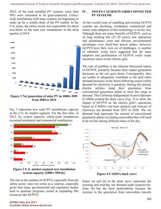
Fig. 1 shows the amount of net generation of solar PV
in the U.S. from 2004 to 2014. This figure backs the
claims that the growing popularity of Solar PV is a
trend that will continue to rise. Although our survey
yielded mixed reports as to when PV solar will be at
grid parity with traditional generation sources, a
common underlying theme among many researchers
is that this will likely happen sooner than later. The
Rocky Mountain Institute recently released a report
that suggests that grid parity will be achievable by
2030 [8]. Scientists at the Argonne National Lab in
Illinois have argued that this may happen by 2025
while the National Renewable Energy Laboratory
(NREL) have publicly suggested that due to the rapid
growth of GCPVS, grid parity may even happen as
early as 2017 [9].In a survey of select International
Energy Agency (IEA) member countries released in](https://image.slidesharecdn.com/81areviewongrid-connectedpvsystem-180808041545/85/A-Review-on-Grid-Connected-PV-System-2-320.jpg)
![International Journal of Trend in Scientific Research and Development, Volume 1(4), ISSN: 2456-6470 www.ijtsrd.com
562
IJTSRD | May-Jun 2017
Available Online @www.ijtsrd.com
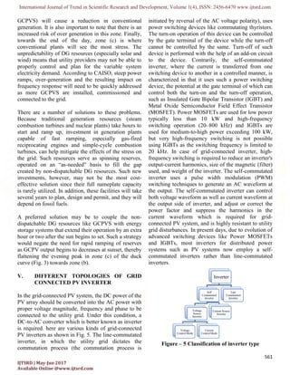
In the self-commutated inverters may be voltage
source inverter (VSI) or current source inverter (CSI)
based on voltage or current waveforms at their input
DC side. In VSI, the input side is a DC voltage
source, the input voltage holds the same polarity, the
average power flow direction through the inverter is
determined by the polarity of the input DC current,
and at the output side, an AC voltage waveform of the
constant amplitude and variable width can be
obtained. To limit current flow from the inverter to
the utility grid a tie line inductor is used along with
VSI. The input DC side terminals of a VSI are
typically connected in parallel with a relatively large
capacitor that resembles a voltage source.
Parameter Voltage Source Inverter (VSI) Current Source Inverter (CSI)
Power Source The input of VSI is a DC voltage
source having small or negligible
impedance.
The input of a CSI is changeable current from a
DC voltage source having high impedance.
Inpt parameter The input voltage is maintained
constant. The input DC side
terminals of a VSI are connected
in parallel with a capacitor and DC
capacitor is small, cheap and
efficient energy storage.
The input current is constant but adjustable. The
input DC side of a CSI is connected in series
with an inductor, and DC inductor is bulky,
expensive and contributes more losses.
Load dependency The amplitude of output voltage
does not depend on the load.
Contrarily, the waveform of the
output current as well as its
magnitude depends upon the
nature of load impedance.
The amplitude of output current does not depend
on the load. Contrarily, the waveform of output
voltage as well as its magnitude depends upon
the nature of the load impedance.
Associated losses High switching loss but low
conduction loss. Thus total power
loss is low.
Low switching loss but high conduction loss.
Thus, the total power loss is high.
TABLE I. DIFFERENCE BETWEEN VSI AND CSI [10]
In CSI, the input side is a DC current source, the input
current holds the same polarity, and therefore the
average power flow direction through the inverter is
determined by the polarity of the input voltage and at
the output side, an AC current waveform of the
constant amplitude and variable width can be
obtained. The input DC side of the CSI is typically
connected in series with a relatively large inductor
that maintains the current continuity. A VSI can be
operated in voltage control mode as well as in current-
control mode and in many times, VSI with current
control mode is preferred for grid-connected PV
system. In Table 1, some basic differences between a
VSI and a CSI are presented.
Figure 2(A) Line-commutated Figure 2(B) Self Commutated
Fig. 2(A), Fig. 2(B) shows configurations of line-
commutated CSI and self-commutated VSI.
For the inverter of stand-alone PV system without any
grid connection, voltage control mode should be used.
However, both voltage control mode and current
control mode can be used for the inverter of grid-
connected PV system. In grid-connected PV system,
inverter with the current control mode is extensively](https://image.slidesharecdn.com/81areviewongrid-connectedpvsystem-180808041545/85/A-Review-on-Grid-Connected-PV-System-5-320.jpg)
![International Journal of Trend in Scientific Research and Development, Volume 1(4), ISSN: 2456-6470 www.ijtsrd.com
563
IJTSRD | May-Jun 2017
Available Online @www.ijtsrd.com
used because a high power factor can be obtained by a
simple control circuit, and also suppression of
transient current is possible when any grid
disturbances occur.
VI. CONCLUSIONS
Although the solar PV market has experienced
astronomical levels of growth and cost reductions in
recent years, there are many technical challenges and
economic realities that need to be reconciled in order
for DG resources like GCPVS to be at parity with
conventional generation. For successful mass
adoption of GCPVs, new technologies must be
developed that will allow the inverter to do more than
just provide DC/AC conversions. Modern grid-
interactive inverters will need to provide Volt/VAR
control (power factor and voltage stabilization),
frequency regulation, enable storage and utilize
modern communications protocols, all at a reasonable
cost. This new generation of inverters has been rightly
termed “smart inverters”.
Future GCPVS design will require inverters to
monitor, react to and adjust their output based on
instantaneous feedback from the grid. The inverter
will also be able to save and share data with the
facility management system for trending, predictive,
preventative and corrective maintenance. These new
breed of smart inverters will be able to log several
data like available battery storage hours and capacity
information, alarm on external events and provide day
to day power management information. Rethinking
the role and capability of the inverters can foster the
mass adaption of GCPVS and equally help to create
and support a more reliable grid.
REFERENCES
[1] G. Ishikawa T, “Grid-connected photovoltaic
power systems: survey of inverter and related
protection equipments”. Report IEA (International
Energy Agency) PVPS T5-05; 2002.
[2] Trends in Photovoltaic Applications. Survey
report of selected IEA countries between 1992 and
2013. Photovoltaic. Power Systems Program, Report
IEA-PVPS T1-13; 2014; 2014.
[3] U.S. Energy Information Agency. United States
electricity profile. Summary statistics for supply and
disposition of electricity, 1990–2012; 2012.
[4] Wong L. “A review of transmission losses in
planning studies”. Technical report. Electricity
Analysis Office, Electricity Supply Analysis Division,
California Energy Commission; August 2011.
[5] Verhoeven B. “Utility Aspects of Grid Connected
Photovoltaic Power Systems. International Energy
Agency Photovoltaic Power Systems”, IEA PVPS T5-
01: 1998. [Online]. Available: www.iea-pvps.org et
al.. 1998.
[6] Feldman G, Barbose D, Margolis R, Wiser R,
Darghouth N, Goodrich A. “Photovoltaic (PV) pricing
trends: historical, recent, and near-term projections”.
Technical report. National Renewable Energy
Laboratory (NREL); [November 1, 2012], Issue:
DOE/GO-102012-3839.
[7] Mehta S. Analyst alert: solar PV pricing on the
rise. Greentech Media; 2013.
[8] Peter Bronski, Jon Creyts, Leia Guccione, Maite
Madrazo, James Mandel, Bodhi Rader, et al.”The
economics of grid defection when and where
distributed solar generation plus storage competes
with traditional utility service”, Rocky Mountain
Institute, Boulder, CO (2014).
[9] Koerth-Baker M. Shining light on the cost of solar
energy. National Geographic; 2010.
[10] Azmi SA; Dept. of Electron. & Electr. Eng.,
Univ. of Strathclyde, Glasgow, UK; K. H. Ahmed; S.
J. Finney; B. W. Williams, “Comparative analysis
between voltage and current source inverters in grid-
connected application”. In: Proceedings of IET
Conference on Renewable Power Generation (RPG
2011); 6-8 Sept. 2011. P. 1–6.](https://image.slidesharecdn.com/81areviewongrid-connectedpvsystem-180808041545/85/A-Review-on-Grid-Connected-PV-System-6-320.jpg)