Downloaded 17 times
![IJRET: International Journal of Research in Engineering and Technology eISSN: 2319-1163 | pISSN: 2321-7308
__________________________________________________________________________________________________
Volume: 03 Issue: 05 | May-2014, Available @ http://www.ijret.org 401
A FUZZY BASED PV FED BRUSHLESS DC MOTOR
Vinay P1
, Manju Ann Mathew2
1
M.Tech Scholar, Department of EEE, Mar Baselios College of Engineering & Technology, Kerala, India
2
Assistant Professor, Department of EEE, Mar Baselios College of Engineering & Technology, Kerala, India
Abstract
Renewable energy sources have now become common much more owing to its necessity rather than effectiveness. Of the various
renewable energy sources, Solar Photovoltaic is one among the cheapest and widely used. Maximum Power Point Techniques are
used to extract the maximum power from a PV module and the fuzzy based MPPT technique has been found to provide better results
for randomly varying atmospheric conditions as compared to other methods. Induction Motors have been in use for years and now
are being replaced by Brushless DC Motors owing to their advantages. The main advantages being a higher efficiency and noiseless
operation. For the effective regulation of MPPT, we make use of DC – DC converters. Sepic converters has found to extract more
power as compared to other buck – boost converters such as Cuk or fly back. In this work, a Fuzzy based MPPT uses a Sepic
converter which drives a BLDC motor.
Keywords: Solar PV, Maximum Power Point Tracking, Sepic Converter, Brushless DC Motor
-----------------------------------------------------------------------***-------------------------------------------------------------------
1. INTRODUCTION
Solar Photovoltaic have gained prominence over the years
since it is pollution free, world wide availability etc. But the
fact is that it is required to meet the needs of the current power
requirements. The modelling of PV modules have been done
in various literatures [1]. For extracting the power from a PV
module, we make use of Maximum Power Point Tracking
algorithms. The heart of any MPPT technique is a DC – DC
converter which regulates the source impedance which varies
with atmospheric conditions and the converter duty ratio is
changed to match the load impedance so that maximum power
transfer occurs [2]. Of the various available Buck boost
configurations, a Single Ended Primary Inductor Converter
(SEPIC) has found to possess several advantages over other
configurations such as Cuk, Flyback, and Zeta etc. The main
and notable advantage being that of a non-inverted output.
The advancement of power electronics and evolution of
control techniques enabled the use of Induction motors for
most of the Industrial applications. But now, Induction motors
are being replaced by BLDC motors which have a higher
efficiency as compared to Induction motors, high Speed –
Torque characteristics and reduced size of machine etc. A
BLDC motor can infact be considered as a DC motor which
runs on AC power. In order to drive BLDC motors, we have to
use an inverter whose gate pulse are generally created from
the hall voltage of the motor extracted with Hall Effect
sensors.
In this work, a PV system with varying environmental
conditions are considered and for such conditions we require
MPPT techniques. A Fuzzy based MPPT system has proven to
extract much more power with low settling time and little
dynamic response. In fact a sepic converter can a little more
power as compared to Cuk converter. A BLDC motor is
driven through an inverter interface. The overall block
diagram is shown in figure 1.
PV
Module
SEPIC
CONVERTER
FUZZY BASED
MPPT
VOLTAGE SOURCE
INVERTER
BRUSHLESS DC
MOTOR
CONTROL
SIGNAL
Duty
Cycle
V & I Hall Voltage
Fig -1: Block Diagram of the Overall System
The hall sensor provides the required control strategy for
driving the inverter. The speed is fed back to the inverter to
make it a constant speed variable load motor.
The first part of the paper deals with the modelling and
simulation of PV module. The modelling of the system based
on MatlabSimulink has been proposed in many papers. The
next is the modelling of the Fuzzy based MPPT and is
followed by the sepic converter fed BLDC motor simulation
and analysis of the motor parameters are done.
2. MODELLING OF PV MODULE
A photovoltaic cell is one which converts incoming sunlight
into electric current by means of photoelectric effect. It is
basically a p-n junction fabricated in a wafer. The output of a
PV cell is very low and hence these cells are connected in
series and parallel to increase the voltage and current levels.](https://image.slidesharecdn.com/afuzzybasedpvfedbrushlessdcmotor-140813054820-phpapp01/75/A-fuzzy-based-pv-fed-brushless-dc-motor-1-2048.jpg)
![IJRET: International Journal of Research in Engineering and Technology eISSN: 2319-1163 | pISSN: 2321-7308
__________________________________________________________________________________________________
Volume: 03 Issue: 05 | May-2014, Available @ http://www.ijret.org 402
Since a PV cell exhibits nonlinear relation between voltage
and current for varying levels of temperature and Irradiance
levels. A solar cell can be modelled by using a one diode
model, which is the most widely used method. We can also a
two diode model or a three diode model for modelling a PV
cell. In this work, a single diode mode is considered. In a sone
diode model, a PV cell is modelled as a variable current
source in anti-parallel with a diode, also a series and shunt
resistance (RS & RP) [4].
The one diode model is shown in figure 2.
Iph
RS
Rp
+
-
Vpv
Ipv
ID
Fig -2: One Diode Equivalent circuit of PV cell
The output of PV cell is given by
𝐼 = 𝑁p 𝐼ph – 𝑁p 𝐼o 𝑒𝑥𝑝
q V/Ns + IRs/Np
AkT
− 1 –
𝑉 + 𝐼𝑅s
𝑅p
where, I is the current, V is the voltage of the PV module, Iph
is the photo-current, I0 is the reverse saturation current, Np is
the number of cells connected in parallel, Ns is the number of
cells connected in series, q is the charge of an electron
(1.6*10-19
C), k is Boltzmann’s constant (1.38*10-23J/K), A is
p-n junction ideality factor, (1 < a < 2, a = 1 being the ideal
value), and T is the PV module temperature.
For a solar cell, the only generated current is by means of a
photo current which is directly dependent on temperature as
well as irradiance level given by
𝐼ph = 𝐼sc + 𝑘1 𝑇 − 𝑇ref 𝐺
where Isc is the short circuit current of the PV cell, K1 is the
short-circuit current/temperature coefficient T is the present
atmospheric temperature and Tref is the temperature at nominal
condition (250o
C and 1000W/m2
), G is the present irradiance
level.
The P-V and I-V characteristics of a PV cell are shown in
figure 3. The maximum power is attained when the cell
operates at Imp and Vmp.
Fig -3: Current-voltage and power-voltage characteristics of a
solar cell
The PV module considered for simulation was Tata TP 250
Series with specifications at Nominal Operating Cell
Temperature (NOCT – 20o
C & 800 W/m2
) was considered
rather than Standard Test Condition (STC – 25o
C &
1000W/m2
).
The electrical parameters of the TP 250 series PV module is as
shown in Table 1.
Table -1: PV Module Parameters
Electrical Parameters Value
Maximum Power (Pmax) 180
Voltage at Pmax (Vmp) 26.7
Current at Pmax (Imp) 6.74
Open Circuit Voltage (Voc) 32.8
Short Circuit Current (Isc) 7.35
Number of Series Cells (Ns) 60
Number of Parallel Cells (Np) 1
The simulated PV module is shown in figure 3.
Fig -4: PV module model
(1)
(2)](https://image.slidesharecdn.com/afuzzybasedpvfedbrushlessdcmotor-140813054820-phpapp01/75/A-fuzzy-based-pv-fed-brushless-dc-motor-2-2048.jpg)
![IJRET: International Journal of Research in Engineering and Technology eISSN: 2319-1163 | pISSN: 2321-7308
__________________________________________________________________________________________________
Volume: 03 Issue: 05 | May-2014, Available @ http://www.ijret.org 403
3. FUZZY BASED MPPT TECHNIQUE
Maximum Power Point Tracking algorithms are used to find
the optimum point of voltage and current at which the
maximum power can be extracted from a PV module. There
are several MPPT techniques ranging from simple to complex
and very complex. The simple MPPT techniques includes the
Perturb and Observe method (P&O) and Incremental
Conductance Method (ICM) [3]. The Fuzzy based MPPT
technique has become common due to the advent of DSP,
FPGA etc. Also, the fuzzy based system have found to extract
much more power compared some of the commonly used
techniques. The main advantages of a fuzzy based system is
that it offers a better performance, robust and also it doesn’t
require the knowledge of the exact system to act upon. The
Fuzzy Logic Control consist of Fuzzification, Inference (Rule
Base) and Defuzzification as shown in figure 5.
FUZZIFICATION INFERENCE DEFUZZIFICATION
RULE BASE
ΔPPV
ΔVPV
ΔD
Fig -5: Fuzzy Logic Controller
During the Fuzzification process, the input variables are
transformed into a linguistic variable based on crisp sets of
membership function. The number of membership functions
used depends on the accuracy of the controller, but it usually
varies between 5 and 7. The seven fuzzy levels used are
namely - NB (Negative Big), NM (Negative Medium), NS
(Negative Small), NZ (Negative Zero), ZE (Zero), PZ
(Positive Zero), PS (Positive Small), PM (Positive Medium)
and PB (Positive Big) [5]. In most of the works, the fuzzy
based MPPT has two inputs and one output. The two inputs
being Error and change in error given by
𝐸 𝑘 =
𝛥𝐼
𝛥𝑉
+
𝐼
𝑉
𝛥𝐸 𝑘 = 𝐸 𝑘 – 𝐸 𝑘 − 1
where, I is output current from PV array; V is output voltage
from array, 𝛥𝐼 = 𝐼 𝑘 − 𝐼 𝑘 − 1 , and 𝛥𝑉 = 𝑉(𝑘) −
𝑉(𝑘 − 1).
The Membership Functions used are shown in figure 6.
(a)
(b)
(c)
Fig -6 Fuzzy Membership Function
(a) Input – Error (b) Input – Error Change (c) Output- Delta D
The output of the fuzzy logic converter is usually a change in
the duty ratio of the power converter, ΔD, or a change in the
reference voltage of the DC-link, ΔV. The rule base, also
known as rule base lookup table or fuzzy rule algorithm,
associates the fuzzy output to the fuzzy inputs based on the
power converter used. The advantages of these controllers,
besides dealing with imprecise inputs, not needing an accurate
mathematical model and handling nonlinearity, are fast
convergence and minimal oscillations around the MPP.
Furthermore, they have been shown to perform well under
step changes in the irradiation.
Next comes the inference part, which can be carried out using
many of the available methods – Mamdani’s method is the
most widely used technique. The Final stage is the
defuzzification, which is done using the centroid method
produces the Output which is the required duty cycle.
(3)
(4)](https://image.slidesharecdn.com/afuzzybasedpvfedbrushlessdcmotor-140813054820-phpapp01/75/A-fuzzy-based-pv-fed-brushless-dc-motor-3-2048.jpg)
![IJRET: International Journal of Research in Engineering and Technology eISSN: 2319-1163 | pISSN: 2321-7308
__________________________________________________________________________________________________
Volume: 03 Issue: 05 | May-2014, Available @ http://www.ijret.org 404
4. SEPIC CONVERTER
The heart of any MPPT system is a DC – DC converter, it is
because it is the converter duty ratio that matches the varying
source impedence of PV panel in order to attain the maximum
power. Almost any DC – DC converter can be used, for this
work a SEPIC converter is being used. A Sepic converter has
been found to extract somewhat more power compared to
other methods. Also the input current ripple while used for
MPPT applications have been found low for a Sepic converter.
A Sepic converter driving a constant load is shown in figure 7.
L1 C1
L2
C2
D
T
+
-
VIN RL
Fig -7 SEPIC Converter
The output voltage and current are given by
𝑉O
𝑉i
=
𝐷
1 − 𝐷
𝐼O
𝐼S
=
1 − 𝐷
𝐷
The design equations are given by
𝐿1 , 𝐿2 =
𝑉dc 𝐷
𝛥𝐼1 𝑓
𝐶1 =
𝐼O 𝐷
𝛥𝑉C1 𝑓
𝐶2 =
𝐼O 𝐷
0.5 𝛥𝑉C2 𝑓
5. BRUSHLESS DC MOTOR
Brushless DC motors have higher power density due to lack of
copper losses as they do not require mechanical commutation
mechanisms which results in compact and robust structures. A
BLDC motor is a synchronous motor that uses a rotor position
sensor and inverter to control the armature currents. Usually
BLDC motors are used where efficiency is a cause of concern
or where the spikes created by commutators re to be avoided.
There are mainly two types of BLDC motors – Trapezoidal
type and Sinusoidal type. For Trapezoidal type, the back emf
is trapezoidal in shape and their phases are supplied with quasi
square wave for ripple free torque operation. On the other
hand, the sinusoidal type requires a sinusoidal phase currents.
The commutation process of a BLDC motor are performed by
an inverter and a rotor position sensor [6].
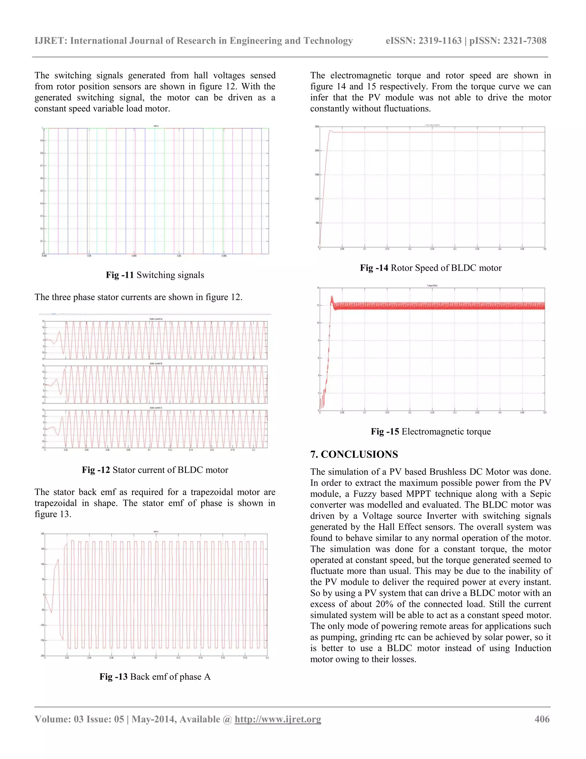
The electronic commutator generates the switching pulse for
the voltage source inverter. The rotor position are sensed by
the hall effect sensor and emf signals are generated. These emf
signals are decoded to get the respective switching signals as
shown in Table 1 [7].
Table -1: Switching Signals based on Hall Effect sensor
Hall Signals Switching Signals
Ha Hb Hc S1 S2 S3 S4 S5 S6
0 0 0 0 0 0 0 0 0
0 0 1 0 0 0 1 1 0
0 1 0 0 1 1 0 0 0
0 1 1 0 1 0 0 1 0
1 0 0 1 0 0 0 0 1
1 0 1 1 0 0 1 0 0
1 1 0 0 0 1 0 0 1
1 1 1 0 0 0 0 0 0
A BLDC motor can be analysed by using the following
𝑉a
𝑉b
𝑉c
=
𝑅 0 0
0 𝑅 0
0 0 𝑅
𝑖a
𝑖b
𝑖c
+
𝐿 − 𝑀 0 0
0 𝐿 − 𝑀 0
0 0 𝐿 − 𝑀
𝑝
𝑖a
𝑖b
𝑖c
+
𝑒a
𝑒b
𝑒c
where L is the self-inductance of each phase, M is the mutual
inductance between any two phases Va,Vb,Vc are the phase
voltages, ia, ib, ic are the phase currents ea, eb, ec are the back
emf signals of BLDC motor and p is the differential operator.
The dynamic equations for mutual inductance
𝑉a = 𝑅𝑖a + 𝐿
𝑑
𝑑𝑡
(𝑖a) + 𝑒a
𝑉b = 𝑅𝑖b + 𝐿
𝑑
𝑑𝑡
(𝑖b) + 𝑒b
𝑉c = 𝑅𝑖c + 𝐿
𝑑
𝑑𝑡
(𝑖c) + 𝑒c
The electromagnetic torque is given by
𝑇e =
1
𝜔
𝑒a 𝑖a + 𝑒b 𝑖b + 𝑒c 𝑖c
The mechanical torque is given by
𝑇m = 𝐽
𝑑𝜔
𝑑𝑡
+ 𝐵𝜔 + 𝑇L
(5)
(6)
(7)
(8)
(9)
(10)
(11)
(13)
(12)
(15)
(14)](https://image.slidesharecdn.com/afuzzybasedpvfedbrushlessdcmotor-140813054820-phpapp01/75/A-fuzzy-based-pv-fed-brushless-dc-motor-4-2048.jpg)
![IJRET: International Journal of Research in Engineering and Technology eISSN: 2319-1163 | pISSN: 2321-7308
__________________________________________________________________________________________________
Volume: 03 Issue: 05 | May-2014, Available @ http://www.ijret.org 405
Where J is the moment of inertia of drive, B is the damping
constant, TL is the load torque and ω is the rotor speed.
The relation between torque and speed is given by
𝑇L ∝ 𝜔2
The three phase BLDC motor is primarily operated on a two
phase basis, i.e.: the two phases which has the highest torque
sensed by the rotor position are operated. The signals from the
rotor position sensor generate a three digit number which
varies for a 60o
as shown in figure 8. It also features ideal
current and back emf waveforms. Each time interval starts
when stator and rotor field lines are 120o
apart and end when
they are 60o
apart [8].
Fig -8 Back-emf’s, phase currents and position sensor signals
The electrical motor parameters are shown in table 2.
Table -2: Motor Specifications
Parameter Value
Armature Inductance (La) 8.5 mH
Armature Resistance (Ra) 2.875 Ω
Rotor Inertia (J) 0.8 e-3 Kgm2
Damping constant (B) 1 e-3 N.m.s/rad
Back EMF constant (kb) 0.175 V.Sec
6. MODELLING AND SIMULATION
The simulations were carried out in Matlab™/Simulink™.
The temperature and Irradiance level are provided on the basis
of historically available data and hence it is a variable
environmental condition [9]. The simulation of the fuzzy logic
controller is shown in figure 9.
Fig -9 Simulation of FLC
The fuzzy based MPPT technique was found to possess much
more efficiency for the provided Irradiance and Temperature
levels. Also a Sepic converter was effective during
comparison with an ordinary Buck-Boost converter and a Cuk
converter. The Simulation diagram of a Sepic converter is
shown in figure 10. The overall circuit simulation is featured
in figure 11.
Fig -10 Sepic Converter
The converter simulation was done for an initial duty ratio of
0.5. The fuzzy based system was able to extract about 230W
from a 250 W PV panel which was used for the motor drive.
Fig -11 Overall Simulation Diagram](https://image.slidesharecdn.com/afuzzybasedpvfedbrushlessdcmotor-140813054820-phpapp01/75/A-fuzzy-based-pv-fed-brushless-dc-motor-5-2048.jpg)
![IJRET: International Journal of Research in Engineering and Technology eISSN: 2319-1163 | pISSN: 2321-7308
__________________________________________________________________________________________________
Volume: 03 Issue: 05 | May-2014, Available @ http://www.ijret.org 407
REFERENCES
[1] Marcelo G, Gazoli J. and Filho E., “Comprehensive
Approach to Modeling and Simulation of Photovoltaic
Arrays”, IEEE Transactions on Power Electronics,
Vol. 24, No. 5, May 2009, pp. 1198-1208.
[2] Esram T. and Chapman P., “Comparison of
Photovoltaic Array Maximum Power Point Tracking
Techniques”, IEEE Transactions on Energy
Conversion, Vol. 22, No. 2, June 2007, pp. 439-449.
[3] Subudhi B. and Pradhan R., “A comparative study on
maximum powerpoint tracking techniques for
photovoltaic power systems”, IEEE Transactions on
Sustainable Energy, vol. 4, no. 1, January 2013, pp. 89-
98.
[4] Gow, J.A. and Manning, C.D. “Development of a
photovoltaic array model for use in power-electronics
simulation studies,” IEEE Proceedings on Electric
Power Applications, Volume:146 , Issue: 2, pp. 193 –
200, March 1999.
[5] Ahmed M. Othman, Mahdi M.M. El-arini, Ahmed
Ghitas, Ahmed Fathy, “Realworld maximum power
point tracking simulation of PV system based on Fuzzy
Logic control,” NRIAG Journal of Astronomy and
Geophysics, January 2014, 186–194.
[6] R. Feyzi, S. A. KH. Mozaffari Niapour, S. Danyali, M.
Shafiei, “Supplying a Brushless DC Motor by Z-Source
PV Power Inverter with FLC-IC MPPT by DTC Drive”
Proceedings of the IEEE International Conference on
Electrical Machines and Systems, October,2010,pp.694
-699
[7] Sreedevi S Nair, Mini Rajeev “Design and Simulation
of PV Powered PMBLDC Motor for Water Pumping”
Proceedings of Third Biennial National Conference,
NCNTE, February, 2012.pp.65-70
[8] S. A. K. Mozafari Niapoor, S. Danyali, M. B. B.
Sharifian, “PV Power System Based MPPT Z-Source
Inverter to Supply a Sensorless BLDC Motor,” IEEE
Power Electronics & Drive Systems & Technologies
Conference (PEDSTC), February, 2010,pp.111-116.
[9] Neena Sugathan, V. Biju, G Renuka, “Solar Activity and
regional climate over short tome scales at
Thiruvananthapuram, South Kerala, India,” Indian
Journal of Radio & Space Physics, Vol 42, April 2013,
pp 69-72.
BIOGRAPHIES
Vinay was born in Kerala in 1990. He
completed his Bachelor Degree from
University of Kerala. He is currently
pursuing his Master’s Degree in Power
Control and Drives from University of
Kerala. His area of interest includes Power
Electronics, Drives and Renewable energy Sources.](https://image.slidesharecdn.com/afuzzybasedpvfedbrushlessdcmotor-140813054820-phpapp01/75/A-fuzzy-based-pv-fed-brushless-dc-motor-7-2048.jpg)

The document discusses a fuzzy-based maximum power point tracking (MPPT) system for solar photovoltaic (PV) fed brushless DC motors, emphasizing the advantages of MPPT techniques using SEPIC converters over traditional methods. It highlights the superiority of fuzzy logic controllers in power extraction under varying environmental conditions, leading to higher efficiency compared to standard buck-boost converters. The study includes simulations demonstrating the effectiveness of the proposed system in optimizing power extraction and motor performance.