Downloaded 24 times
![ENCLOSURES
Explosion Proof Electrical Equipment
Ex Enclosures
EJB
EJB
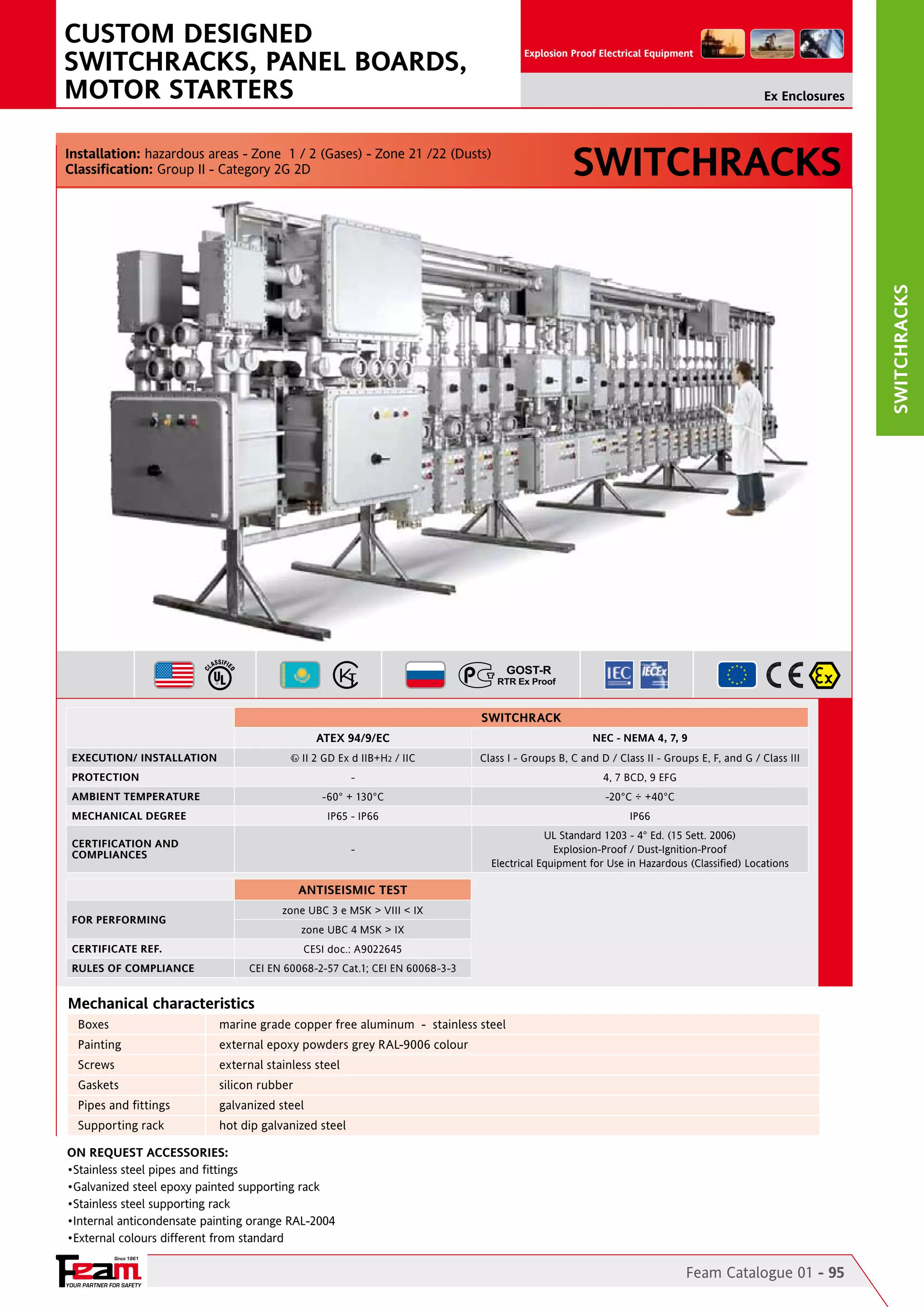
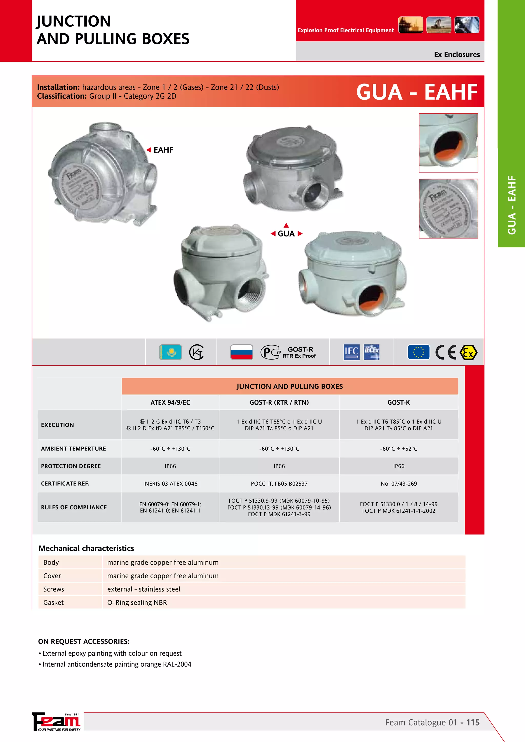
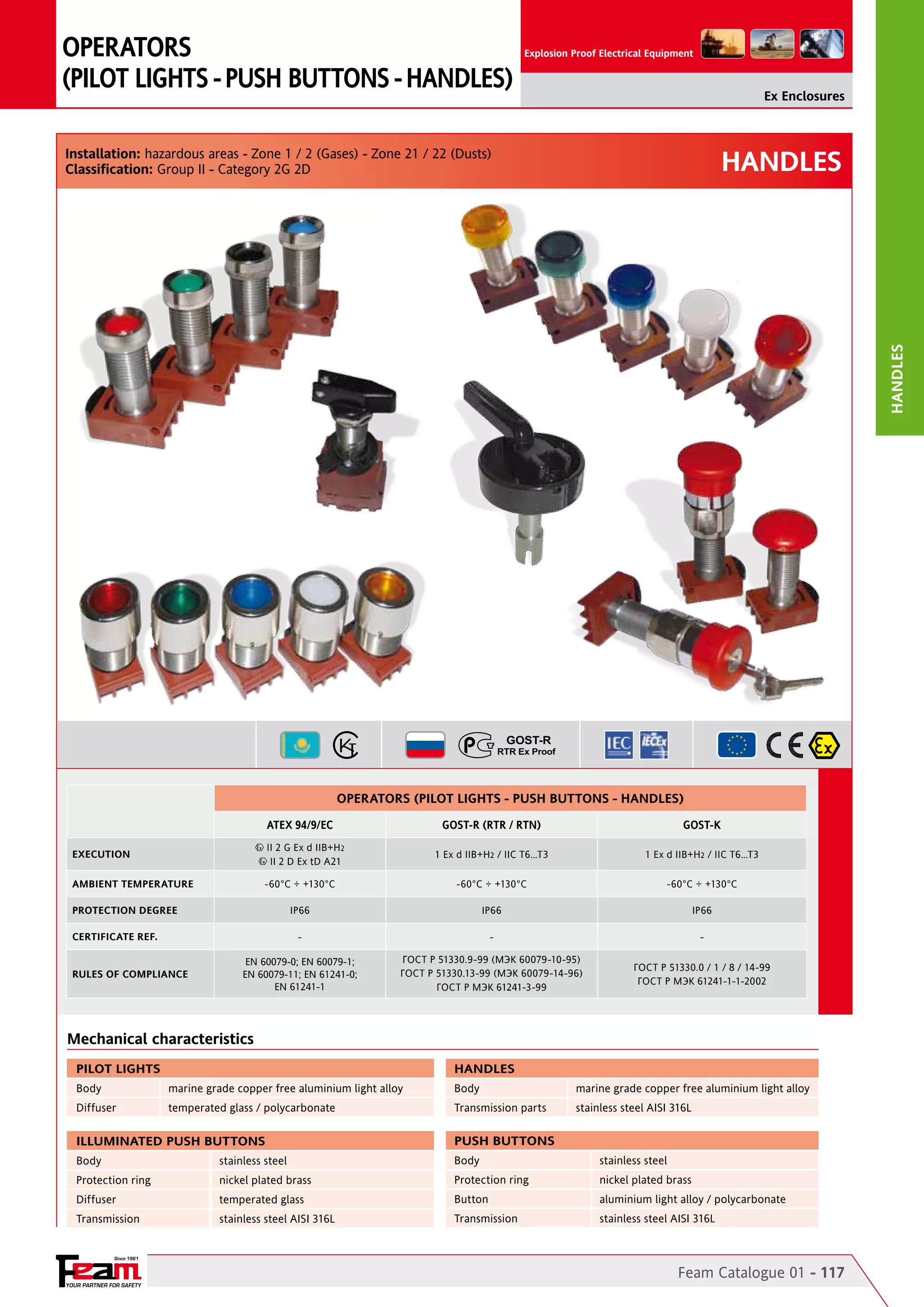
Installation: hazardous areas - Zone 1 / 2 (Gases) - Zone 21 / 22 (Dusts)
Classification: Group II - Category 2G 2D
TERMINAL BOARD
Modular terminal strip / power distribution bars
ATEX 94/9/EC
IEC Ex
GOST-R (RTR / RTN)
GOST-K
II 2 G Ex d IIB+H2 T6
II 2 G Ex d [ia/ib] IIB+H2 T6
II 2 D Ex tD A21 T85°C
1 Ex d IIB+H2 T6
1 Ex d [ia/ib] IIB+H2 T6
A21 TA85°C
1 Ex d IIB+H2 T6
1 Ex d [ia/ib] IIB+H2 T6
A21 TA85°C
-60°C ÷ +130°C
-60°C ÷ +130°C
-60°C ÷ +130°C
-60°C ÷ +130°C
IP66
IP66
IP66
IP66
BKI 08 ATEX 019
IECEx BKI 09.0005
POCC IT. ГБ05.B02537
No. 07/43-269
EN 60079-0; EN 60079-1;
EN 60079-11; EN 61241-0;
EN 61241-1
EN 60079-0; EN 60079-1;
EN 60079-11; EN 61241-0;
EN 61241-1
ГОСТ Р 51330.9-99 (МЭК 60079-10-95)
ГОСТ Р 51330.13-99 (МЭК 60079-14-96)
ГОСТ Р МЭК 61241-3-99
ГОСТ Р 51330.0 / 1 / 8 / 14-99
ГОСТ Р МЭК 61241-1-1-2002
II 2 G Ex d IIB+H2 T6
II 2 G Ex d [ia/ib] IIB+H2 T6
II 2 D Ex tD A21 T85°C
EXECUTION
AMBIENT TEMPERATURE
PROTECTION DEGREE
CERTIFICATE REF.
RULES OF COMPLIANCE
POWER UNITS
Current and voltage transformers / power supplies / rectifiers
ATEX 94/9/EC
IEC Ex
GOST-R (RTR / RTN)
GOST-K
II 2 G Ex d IIB+H2 T6…T3
II 2 D Ex tD A21 T85°C…150°C
1 Ex d IIB+H2 T6…T3
A21 TA85°C…150°C
1 Ex d IIB+H2 T6…T3
A21 TA85°C…150°C
-60°C ÷ +130°C
-60°C ÷ +130°C
-60°C ÷ +130°C
-60°C ÷ +130°C
IP66
IP66
IP66
IP66
II 2 G Ex d IIB+H2 T6…T3
II 2 D Ex tD A21 T85°C…150°C
EXECUTION
AMBIENT TEMPERATURE
PROTECTION DEGREE
CERTIFICATE REF.
BKI 08 ATEX 019
RULES OF COMPLIANCE
IECEx BKI 09.0005
POCC IT. ГБ05.B02537
No. 07/43-269
EN 60079-0; EN 60079-1;
EN 60079-11; EN 61241-0;
EN 61241-1
EN 60079-0; EN 60079-1;
EN 60079-11; EN 61241-0;
EN 61241-1
ГОСТ Р 51330.9-99 (МЭК 60079-10-95)
ГОСТ Р 51330.13-99 (МЭК 60079-14-96)
ГОСТ Р МЭК 61241-3-99
ГОСТ Р 51330.0 / 1 / 8 / 14-99
ГОСТ Р МЭК 61241-1-1-2002
CONTROL AND SIGNALLING UNITS
Lighting, power and receptacles distribution panelboards / switchracks / dol and dy motor starters / control and signalling panelboards
IEC Ex
GOST-R (RTR / RTN)
GOST-K
II 2 G Ex d IIB+H2 T6…T3
II 2 (1) G Ex d [ia] IIB+H2 T6…T3
II 2 (2) G Ex d [ib] IIB+H2 T6…T3
II 2 D Ex tD A21 T85°C…150°C
1 Ex d IIB+H2 T6…T3
1 Ex d [ia] IIB+H2 T6…T3
1 Ex d [ib] IIB+H2 T6…T3
A21 TA85°C…150°C
1 Ex d IIB+H2 T6…T3
1 Ex d [ia] IIB+H2 T6…T3
1 Ex d [ib] IIB+H2 T6…T3
A21 TA85°C…150°C
-60°C ÷ +130°C
-60°C ÷ +130°C
-60°C ÷ +130°C
-60°C ÷ +130°C
IP66
IP66
IP66
IP66
BKI 08 ATEX 019
IECEx BKI 09.0005
POCC IT. ГБ05.B02537
No. 07/43-269
EN 60079-0; EN 60079-1;
EN 60079-11; EN 61241-0;
EN 61241-1
EN 60079-0; EN 60079-1;
EN 60079-11; EN 61241-0;
EN 61241-1
ГОСТ Р 51330.9-99 (МЭК 60079-10-95)
ГОСТ Р 51330.13-99 (МЭК 60079-14-96)
ГОСТ Р МЭК 61241-3-99
ГОСТ Р 51330.0 / 1 / 8 / 14-99
ГОСТ Р МЭК 61241-1-1-2002
ATEX 94/9/EC
EXECUTION
II 2 G Ex d IIB+H2 T6…T3
II 2 (1) G Ex d [ia] IIB+H2 T6…T3
II 2 (2) G Ex d [ib] IIB+H2 T6…T3
II 2 D Ex tD A21 T85°C…150°C
AMBIENT TEMPERATURE
PROTECTION DEGREE
CERTIFICATE REF.
RULES OF COMPLIANCE
Mechanical characteristics
Body/cover
Screws
Internal mounting plate
Fixing
Hinges
marine grade copper free aluminium light alloy
stainless steel
hot dip galvanized steel / aluminum
fixing lugs AL UNI EN 1706:1999 - galvanized steel stirrups sp. 10mm (EJB71 AND EJB91 ONLY)
On the long side - cast on enclosure body and cover
On Request Accessories:
•External epoxy painting with colour on request
•Internal anticondensate painting orange RAL-2004
•O-Ring gaskets on cover
•Glass windows on cover
•Drain and breather valves
Since 1961
YOUR PARTNER FOR SAFETY
Feam Catalogue 01 - 97](https://image.slidesharecdn.com/a-131107095443-phpapp01/75/FEAM-Enclosures-Hazardous-Area-Explosion-Proof-Enclosures-ATEX-IECEx-Inmetro-GOST-R-GOST-K-NEC505-3-2048.jpg)
![Ex Enclosures
EJB Technical features
A
[mm]
B
[mm]
C
[mm]
D
[mm]
E
[mm]
F
[mm]
G
[mm]
EJB-11
175
175
-
125
78
165
EJB-21
285
245
267
169
160
EJB-22
300
200
222
177
EJB-30
415
315
340
168
CODE
H
[mm]
L
[mm]
INT. PLATE
X - Y [mm]
WEIGHT
[Kg]
DETAIL
90
115
115
95 - 95
3,60
A
276
122
217
175
180 - 140
10,50
A
195
221
130
240
140
235 - 135
12,50
A
280
306
120
340
245
325 - 225
18,50
A
EJB-31
415
315
340
250
280
306
200
340
245
325 - 225
20,50
A
EJB-51
568
365
388
257
360
376
203
495
295
460 - 260
36,50
A
EJB-61
670
470
490
360
500
470
310
595
395
560 - 360
57,00
A
EJB-63
670
470
490
235
500
470
184
595
395
560 - 360
47,00
A
742
542
572
425
500
456
360
645
445
590 - 390
110,00
A
960
660
700
460
700
526
370
830
530
758 - 448
202,00
A
EJB-2
365
255
340
193
325
300
152
327
218
300 - 190
17,00
B
EJB-3
468
310
395
210
432
355
168
440
282
400 - 240
23,00
B
EJB-4
492
380
470
270
450
430
217
458
346
410 - 300
33,00
B
EJB-6
610
415
510
327
560
455
260
564
184
525 - 325
65,00
B
Reference details
A
A
E
HxL
C
B
S.r.l.
CUSTODIA tipo
ENCLOSURE type
Via M. Pagano, 3
I-20090 Trezzano s/N
ITALY
www.feam-ex.com
0722
II2 GD
year s/n
BKI 08 ATEX 019
V
Hz
Ex d IIB+H
Ta
A
2
T
Ex tD A21 IP66 T
W
VA
°C
NON APRIRE SOTTO TENSIONE
DO NOT OPEN WHILE ENERGIZED
Ad ogni apertura del coperchio
ripristinare il grasso ai siliconi.
accertarsi che le valvole di respirazione
e drenaggio siano sempre chiuse
Renew silicone grease every tyme
cover is opened. and make sure
that the drain and breather valves
are always closed.
11.00.88
D
G
F
B
C
B
A
E
HxL
G
D
EJB
EJB-71
EJB-91
F
Since 1961
98 - Feam Catalogue 01
YOUR PARTNER FOR SAFETY](https://image.slidesharecdn.com/a-131107095443-phpapp01/75/FEAM-Enclosures-Hazardous-Area-Explosion-Proof-Enclosures-ATEX-IECEx-Inmetro-GOST-R-GOST-K-NEC505-4-2048.jpg)
![Ex Enclosures
EJB Glass Windows on Cover
ENCLOSURE CODE
DIMENSIONS
WINDOW
CODE
EJB-11
EJB-21
EJB-22
EJB-30/31
EJB-51
EJB-61/63
EJB-71
EJB-91
A [mm]
B [mm]
F1
X
X
X
X
X
X
X
X
60
60
C
F2
X
X
-
X
X
X
X
X
75
75
C
F3
-
X
X
X
X
X
X
X
110
75
C
F4
-
X
-
X
X
X
-
-
150
75
C
F5
-
-
-
X
X
X
-
-
150
150
C
F6
-
-
-
X
X
X
-
-
300
75
C
F7
-
-
-
X
X
X
-
-
300
150
C
F8
-
-
-
-
-
X
-
-
300
300
C
F9
-
-
-
-
-
X
-
-
450
300
C
Reference details
C
plate
B
PLATE X-Y
S.r.l.
CUSTODIA tipo
ENCLOSURE type
Via M. Pagano, 3
I-20090 Trezzano s/N
ITALY
www.feam-ex.com
0722
year s/n
BKI 08 ATEX 019
V
II2 GD
Ex d IIB+H
Hz
Ta
A
2
T
Ex tD A21 IP66 T
W
VA
°C
NON APRIRE SOTTO TENSIONE
DO NOT OPEN WHILE ENERGIZED
Ad ogni apertura del coperchio
ripristinare il grasso ai siliconi.
accertarsi che le valvole di respirazione
e drenaggio siano sempre chiuse
Renew silicone grease every tyme
cover is opened. and make sure
that the drain and breather valves
are always closed.
11.00.88
A
EJB Indicative quantity of terminals and relevant section
CODE
SECT. 2,5
[mm/sq]
SECT. 6,0
[mm/sq]
SECT. 10,0
[mm/sq]
SECT. 16,0
[mm/sq]
SECT. 35,0
[mm/sq]
SECT. 50,0
[mm/sq]
SECT. 70,0
[mm/sq]
SECT. 240,0 INT. PLATE X - Y
[mm/sq]
[mm]
EJB-11
12 x 1
8 x 1
6 x 1
4 x 1
2 x 1
-
-
-
95 - 95
EJB-21
30 x 1
20 x 1
14 x 1
12 x 1
8 x 1
6 x 1
2 x 1
1 x 1
180 - 140
EJB-22
44 x 1
30 x 1
20 x 1
18 x 1
12 x 1
10 x 1
4 x 1
2 x 1
235 - 135
EJB-30
52 x 2
32 x 2
24 x 2
20 x 2
14 x 2
12 x 1
8 x 1
4 x 1
325 - 225
EJB-31
52 x 2
32 x 2
24 x 2
20 x 2
14 x 2
12 x 1
8 x 1
4 x 1
325 - 225
EJB-51
80 x 2
46 x 2
36 x 2
30 x 2
22 x 2
18 x 2
16 x 1
6 x 1
460 - 260
EJB-61
92 x 3
58 x 3
46 x 3
38 x 3
28 x 3
26 x 2
22 x 2
12 x 1
560 - 360
EJB-63
92 x 3
58 x 3
46 x 3
38 x 3
28 x 3
26 x 2
22 x 2
12 x 1
560 - 360
EJB-71
110 x 3
70 x 3
56 x 3
46 x 3
34 x 3
28 x 2
24 x 2
12 x 1
590 - 390
EJB-91
140 x 3
90 x 3
70 x 3
60 x 3
44 x 3
36 x 3
32 x 2
14 x 2
758 - 448
EJB-2
54 x 1
34 x 1
26 x 1
22 x 1
16 x 1
12 x 1
6 x 1
2 x 1
300 - 190
EJB-3
70 x 2
46 x 2
36 x 2
30 x 2
22 x 2
18 x 1
10 x 1
4 x 1
400 - 240
EJB-4
70 X 2
40 x 2
32 x 2
26 x 2
20 x 2
14 x 2
10 x 1
4 x 1
410 - 300
EJB-6
80 x 3
50 x 3
36 x 3
28 x 3
18 x 3
16 x 2
12 x 2
6 x 1
525 - 325
Since 1961
YOUR PARTNER FOR SAFETY
Feam Catalogue 01 - 99
EJB
Reference details
DETAIL](https://image.slidesharecdn.com/a-131107095443-phpapp01/75/FEAM-Enclosures-Hazardous-Area-Explosion-Proof-Enclosures-ATEX-IECEx-Inmetro-GOST-R-GOST-K-NEC505-5-2048.jpg)
![Ex Enclosures
EJB Body and Cover Enclosures Drilling Layout
QUANTITY ALLOWED ENTRIES FOR
size (from 1 to size 8)
QUANTITY ALLOWED ENTRIES FOR
size (from 1 to size 8)
ENCLOSURE
CODE
DRILLING
AREA A-B
[mm]
1
2
3
4
5
6
7
8
1
2
3
4
5
6
7
8
EJB-11
125x60
4
2
2
1
1
-
-
-
125x60
4
2
2
1
1
-
-
-
EJB-21
200x90
10
7
5
3
2
2
1
-
160x90
8
5
4
3
2
1
1
-
EJB-22
215x130
15 11
8
6
6
3
2
1
110x130
9
5
5
4
2
1
1
1
EJB-30
320x65
13
5
5
4
3
-
-
225x65
9
5
4
3
3
2
-
-
7
DRILLING AREA
C-D [mm]
EJB-31
320x150
28 18
14
11
8
6
3
2
225x150
20
12
9
8
6
5
2
1
EJB-51
460x155
44 27
24
20
12 10
6
3
255x155
24
15
12 11
6
6
3
2
550x250
72 50
36
32
21 21
14
8
350x250
48 30
24 20
12
12
8
6
550x130
36 29
18
16
14
5
4
350x130
24
17
12 10
8
4
3
3
EJB-71
600x270
78 55
50
36
32 21
18
10
400x270
48 35
35 24
20
15 12
6
EJB-91
745x290
112 84 65
55
40 28
23
14
440x290
70
42
35 35
24
18 13
8
EJB-1
175x115
12
6
6
5
3
2
1
1
175x115
12
6
6
5
3
2
1
1
EJB-2
310x105
17 12
10
9
5
4
3
2
200x105
11
8
6
5
3
2
2
1
EJB-3
425x115
30 17
14
12
9
5
4
3
270x115
18
11
8
8
6
3
2
2
EJB-C237
200x60
6
3
2
2
-
-
-
130x60
4
2
2
2
1
-
-
-
4
7
Reference details
EJB Threads comparation table
wall DRILLING AREA
size
UNI 6125
ISO 228/1
ASA B2.1
ISO 965/I
1
GK 1/2”
G 1/2”
1/2” NPT
M20
2
GK 3/4”
G 3/4”
3/4” NPT
M25
3
GK 1”
G 1”
1” NPT
M32
4
GK 1-1/4”
G 1-1/4”
1-1/4” NPT
M40
5
GK 1-1/2”
G 1-1/2” 1-1/2” NPT
M50
6
GK 2”
7
GK 2-1/2”
8
A
GK 3”
B
C
D
ENCLOSURE
CODE
DRILLING AREA E-F
[mm]
MAX OPERATORS
PERMITTED
EJB-11
120x120
6
EJB-21
200x155
12
EJB-22
240x120
305x205
305x205
465x265
575x370
G 3”
3” NPT
M75
M85
Reference details
Cover DRILLING AREA
F
54
EJB-61
G 2-1/2” 2-1/2” NPT
30
EJB-51
M63
30
EJB-31
2” NPT
15
EJB-30
G 2”
56
EJB-63
575x370
56
EJB-71
590x390
48
EJB-91
800x500
54
EJB-2
290x180
24
EJB-3
380x220
40
EJB-4
390x280
47
EJB-6
500x310
55
E
EJB
EJB-61
EJB-63
REMARK: Due to the development of the national and international specifications and of the technology, the above technical characteristics
showed on this bulletin can be considered as binding on our confirmation only.
Since 1961
100 - Feam Catalogue 01
YOUR PARTNER FOR SAFETY](https://image.slidesharecdn.com/a-131107095443-phpapp01/75/FEAM-Enclosures-Hazardous-Area-Explosion-Proof-Enclosures-ATEX-IECEx-Inmetro-GOST-R-GOST-K-NEC505-6-2048.jpg)
![ENCLOSURES
Explosion Proof Electrical Equipment
Ex Enclosures
EJB INX
EJB inx
Installation: hazardous areas - Zone 1 / 2 (Gases) - Zone 21 / 22 (Dusts)
Classification: Group II - Category 2G 2D
TERMINAL BOARD
Modular terminal strip / power distribution bars
ATEX 94/9/EC
IEC Ex
GOST-R (RTR / RTN)
GOST-K
II 2 G Ex d IIB+H2 T6
II 2 G Ex d [ia/ib] IIB+H2 T6
II 2 D Ex tD A21 T85°C
1 Ex d IIB+H2 T6
1 Ex d [ia/ib] IIB+H2 T6
A21 TA85°C
1 Ex d IIB+H2 T6
1 Ex d [ia/ib] IIB+H2 T6
A21 TA85°C
-60°C ÷ +130°C
-60°C ÷ +130°C
-60°C ÷ +130°C
-60°C ÷ +130°C
IP66
IP66
IP66
IP66
BKI 08 ATEX 019
IECEx BKI 09.0005
POCC IT. ГБ05.B02537
No. 07/43-269
EN 60079-0; EN 60079-1;
EN 60079-11; EN 61241-0;
EN 61241-1
EN 60079-0; EN 60079-1;
EN 60079-11; EN 61241-0
EN 61241-1
ГОСТ Р 51330.9-99 (МЭК 60079-10-95)
ГОСТ Р 51330.13-99 (МЭК 60079-14-96)
ГОСТ Р МЭК 61241-3-99
ГОСТ Р 51330.0 / 1 / 8 / 14-99
ГОСТ Р МЭК 61241-1-1-2002
II 2 G Ex d IIB+H2 T6
II 2 G Ex d [ia/ib] IIB+H2 T6
II 2 D Ex tD A21 T85°C
EXECUTION
AMBIENT TEMPERATURE
PROTECTION DEGREE
CERTIFICATE REF.
RULES OF COMPLIANCE
POWER UNITS
Current and voltage transformers / power supplies / rectifier
ATEX 94/9/EC
IEC Ex
GOST-R (RTR / RTN)
GOST-K
II 2 G Ex d IIB+H2 T6…T3
II 2 D Ex tD A21 T85°C…150°C
1 Ex d IIB+H2 T6…T3
A21 TA85°C…150°C
1 Ex d IIB+H2 T6…T3
A21 TA85°C…150°C
-60°C ÷ +130°C
-60°C ÷ +130°C
-60°C ÷ +130°C
-60°C ÷ +130°C
IP66
IP66
IP66
IP66
BKI 08 ATEX 019
IECEx BKI 09.0005
POCC IT. ГБ05.B02537
No. 07/43-269
EN 60079-0; EN 60079-1;
EN 60079-11; EN 61241-0;
EN 61241-1
EN 60079-0; EN 60079-1;
EN 60079-11; EN 61241-0
EN 61241-1
ГОСТ Р 51330.9-99 (МЭК 60079-10-95)
ГОСТ Р 51330.13-99 (МЭК 60079-14-96)
ГОСТ Р МЭК 61241-3-99
ГОСТ Р 51330.0 / 1 / 8 / 14-99
ГОСТ Р МЭК 61241-1-1-2002
II 2 G Ex d IIB+H2 T6…T3
II 2 D Ex tD A21 T85°C…150°C
EXECUTION
AMBIENT TEMPERATURE
PROTECTION DEGREE
CERTIFICATE REF.
RULES OF COMPLIANCE
CONTROL AND SIGNALLING UNITS
Lighting, power and receptacles distribution panelboards / switchracks / dol and dy motor starters / control and signalling panelboards
IEC Ex
GOST-R (RTR / RTN)
GOST-K
II 2 G Ex d IIB+H2 T6…T3
II 2 (1) G Ex d [ia] IIB+H2 T6…T3
II 2 (2) G Ex d [ib] IIB+H2 T6…T3
II 2 D Ex tD A21 T85°C…150°C
1 Ex d IIB+H2 T6…T3
1 Ex d [ia] IIB+H2 T6…T3
1 Ex d [ib] IIB+H2 T6…T3
A21 TA85°C…150°C
1 Ex d IIB+H2 T6…T3
1 Ex d [ia] IIB+H2 T6…T3
1 Ex d [ib] IIB+H2 T6…T3
A21 TA85°C…150°C
-60°C ÷ +130°C
-60°C ÷ +130°C
-60°C ÷ +130°C
-60°C ÷ +130°C
IP66
IP66
IP66
IP66
BKI 08 ATEX 019
IECEx BKI 09.0005
POCC IT. ГБ05.B02537
No. 07/43-269
EN 60079-0; EN 60079-1;
EN 60079-11; EN 61241-0;
EN 61241-1
EN 60079-0; EN 60079-1;
EN 60079-11; EN 61241-0
EN 61241-1
ГОСТ Р 51330.9-99 (МЭК 60079-10-95)
ГОСТ Р 51330.13-99 (МЭК 60079-14-96)
ГОСТ Р МЭК 61241-3-99
ГОСТ Р 51330.0 / 1 / 8 / 14-99
ГОСТ Р МЭК 61241-1-1-2002
ATEX 94/9/EC
EXECUTION
II 2 G Ex d IIB+H2 T6…T3
II 2 (1) G Ex d [ia] IIB+H2 T6…T3
II 2 (2) G Ex d [ib] IIB+H2 T6…T3
II 2 D Ex tD A21 T85°C…150°C
AMBIENT TEMPERATURE
PROTECTION DEGREE
CERTIFICATE REF.
RULES OF COMPLIANCE
Mechanical characteristics
Body & cover
Screws
Internal mounting plate
Fixing
Hinges
Opening handle
stainless steel AISI-316 L
stainless steel
stainless steel / aluminum
fixing lugs stainless steel AISI-316 L - stainless steel stirrups sp.10mm (EJB71 AND EJB91 ONLY)
applied
insulating material fixed on cover by stainless steel screws
On Request Accessories:
•External epoxy painting (any colours)
•Internal anticondensate painting orange RAL-2004
•O-Ring gaskets on cover
•Glass windows on cover
Since 1961
YOUR PARTNER FOR SAFETY
Feam Catalogue 01 - 101](https://image.slidesharecdn.com/a-131107095443-phpapp01/75/FEAM-Enclosures-Hazardous-Area-Explosion-Proof-Enclosures-ATEX-IECEx-Inmetro-GOST-R-GOST-K-NEC505-7-2048.jpg)
![Ex Enclosures
EJB INX Technical features
A
[mm]
B
[mm]
C
[mm]
D
[mm]
E
[mm]
F
[mm]
G
[mm]
H
[mm]
L
[mm]
INT. PLATE
X - Y [mm]
WEIGHT
[Kg]
EJB-21 INX
285
245
260
194
160
230
122
215
175
180 - 140
32,00
A
EJB-22 INX
300
200
215
218
195
188
177
230
130
235 - 135
38,00
A
EJB-30 INX
415
315
330
158
294
290
117
335
235
325 - 225
53,00
A
EJB-31 INX
415
315
330
223
294
290
180
335
235
325 - 225
62,00
A
EJB-51 INX
565
365
400
233
360
335
190
480
280
460 - 260
110,00
A
EJB-61 INX
670
470
485
344
500
437
290
590
390
560 - 360
152,00
A
EJB63 INX
670
470
485
229
500
437
180
590
390
560 - 360
140,00
A
EJB-71 INX
742
542
557
400
500
456
360
645
445
590 - 390
280,00
A
EJB-91 INX
960
660
678
431
600
640
364
843
543
758 - 448
618,00
A
DETAIL
Reference details
A
C
E
A
B
HxL
S.r.l.
CUSTODIA tipo
ENCLOSURE type
Via M. Pagano, 3
I-20090 Trezzano s/N
ITALY
www.feam-ex.com
0722
II2 GD
year s/n
BKI 08 ATEX 019
V
Ex d IIB+H
Hz
Ta
A
2
T
W
Ex tD A21 IP66 T
VA
°C
NON APRIRE SOTTO TENSIONE
DO NOT OPEN WHILE ENERGIZED
Ad ogni apertura del coperchio
ripristinare il grasso ai siliconi.
accertarsi che le valvole di respirazione
e drenaggio siano sempre chiuse
Renew silicone grease every tyme
cover is opened. and make sure
that the drain and breather valves
are always closed.
11.00.88
G
D
EJB inx
CODE
F
EJB Indicative quantity of terminals and relevant section
CODE
SECT. 2,5
[mm/sq]
SECT. 6,0
[mm/sq]
SECT. 10,0
[mm/sq]
SECT. 16,0
[mm/sq]
SECT. 35,0
[mm/sq]
SECT. 50,0
[mm/sq]
SECT. 70,0
[mm/sq]
SECT. 240,0
[mm/sq]
INT. PLATE X - Y
[mm]
EJB-21 INX
30 x 1
20 x 1
14 x 1
12 x 1
8 x 1
6 x 1
2 x 1
1 x 1
180 - 140
EJB-22 INX
44 x 1
30 x 1
20 x 1
18 x 1
12 x 1
10 x 1
4 x 1
2 x 1
235 - 135
EJB-30 INX
52 x 2
32 x 2
24 x 2
20 x 2
14 x 2
12 x 1
8 x 1
4 x 1
325 - 225
EJB-31 INX
52 x 2
32 x 2
24 x 2
20 x 2
14 x 2
12 x 1
8 x 1
4 x 1
325 - 225
EJB-51 INX
80 x 2
46 x 2
36 x 2
30 x 2
22 x 2
18 x 2
16 x 1
6 x 1
460 - 260
EJB-61 INX
92 x 3
58 x 3
46 x 3
38 x 3
28 x 3
26 x 2
22 x 2
12 x 1
560 - 360
EJB-63 INX
92 x 3
58 x 3
46 x 3
38 x 3
28 x 3
26 x 2
22 x 2
12 x 1
560 - 360
EJB-71 INX
110 x 3
70 x 3
56 x 3
46 x 3
34 x 3
28 x 2
24 x 2
12 x 1
590 - 390
EJB-91 INX
140 x 3
90 x 3
70 x 3
60 x 3
44 x 3
36 x 3
32 x 2
14 x 2
758 - 448
Since 1961
102 - Feam Catalogue 01
YOUR PARTNER FOR SAFETY](https://image.slidesharecdn.com/a-131107095443-phpapp01/75/FEAM-Enclosures-Hazardous-Area-Explosion-Proof-Enclosures-ATEX-IECEx-Inmetro-GOST-R-GOST-K-NEC505-8-2048.jpg)
![Ex Enclosures
EJB INX Glass Windows on Cover
WINDOW
CODE
ENCLOSURE CODE
EJB-51
INX
DIMENSIONS
DETAIL
EJB-21
INX
EJB-22
INX
EJB-30/31
INX
EJB-61/63
INX
EJB-71
INX
EJB-91
INX
F1
X
X
X
X
X
X
X
F2
X
-
F3
X
X
X
X
X
X
X
75
75
C
X
X
X
X
X
110
75
C
F4
X
-
X
X
X
-
-
150
75
C
F5
-
-
X
X
X
-
-
150
150
C
A [mm]
B [mm]
60
60
C
F6
-
-
X
X
X
-
-
300
75
C
F7
-
-
X
X
X
-
-
300
150
C
-
-
-
-
X
-
-
300
300
C
-
-
-
-
X
-
-
450
300
C
Reference details
EJB inx
F8
F9
Reference details
plate
B
C
A
S.r.l.
CUSTODIA tipo
ENCLOSURE type
Via M. Pagano, 3
I-20090 Trezzano s/N
ITALY
www.feam-ex.com
0722
II2 GD
year s/n
BKI 08 ATEX 019 Ta
V
Ex d IIB+H
Hz
A
2
T
Ex tD A21 IP66 T
W
VA
°C
NON APRIRE SOTTO TENSIONE
DO NOT OPEN WHILE ENERGIZED
Ad ogni apertura del coperchio
ripristinare il grasso ai siliconi.
accertarsi che le valvole di respirazione
e drenaggio siano sempre chiuse
Renew silicone grease every tyme
cover is opened. and make sure
that the drain and breather valves
are always closed.
11.00.88
PLATE X-Y
EJB INX Body and Cover Enclosures Drilling Layout
QUANTITY ALLOWED ENTRIES FOR
size (from 1 to size 8)
1
2
3
4
5
6
7
8
DRILLING AREA
C-D [mm]
QUANTITY ALLOWED ENTRIES FOR
size (from 1 to size 8)
1
2
3
4
5
6
7
8
ENCLOSURE
CODE
DRILLING AREA
A-B [mm]
EJB-21 INX
200x90
10
7
5
3
2
2
1
-
160x90
8
5
4
3
2
1
1
-
EJB-22 INX
215x130
15 11
8
6
6
3
2
1
110x130
9
5
5
4
2
1
1
1
EJB-30 INX
320x65
13
7
5
5
4
3
-
-
225x65
9
5
4
3
3
2
-
-
14
11
8
225x150
20
12
9
8
6
5
2
1
15
EJB-31 INX
320x150
28 18
6
3
2
EJB-51 INX
460x155
44 27 24 20
12 10
6
3
255x155
24
12 11
6
6
3
2
EJB-61 INX
550x250
72 50 36 32
21 21
14
8
350x250
48 30 24 20
12
12
8
6
EJB-63 INX
550x130
36 29
18
16
14
7
5
4
350x130
24
17
12 10
8
4
3
3
EJB-71 INX
600x270
78 55
50
36
32 21
18
10
400x270
48 35
35 24
20
15 12
6
EJB-91 INX
745x290
112 84 65
55 40 28 23
14
440x290
70 42 35 35
24
18 13
8
Reference details
wall DRILLING AREA
C
D
B
A
Since 1961
YOUR PARTNER FOR SAFETY
Feam Catalogue 01 - 103](https://image.slidesharecdn.com/a-131107095443-phpapp01/75/FEAM-Enclosures-Hazardous-Area-Explosion-Proof-Enclosures-ATEX-IECEx-Inmetro-GOST-R-GOST-K-NEC505-9-2048.jpg)
![Ex Enclosures
EJB INX Body and Cover Enclosures Drilling Layout
Reference details
ENCLOSURE
CODE
DRILLING AREA
E-F [mm]
200x155
12
EJB-22 INX
240x120
15
EJB-30 INX
305x205
30
EJB-31 INX
305x205
30
EJB-51 INX
465x265
54
EJB-61 INX
575x370
56
EJB-63 INX
575x370
56
EJB-71 INX
590x390
48
EJB-91 INX
800x500
F
54
E
EJB-21 INX
EJB inx
Cover DRILLING AREA
MAX OPERATORS
PERMITTED
EJB INX Threads comparation table
size
UNI 6125
ISO 228/1
ASA B2.1
ISO 965/I
1
GK 1/2”
G 1/2”
1/2” NPT
M20
2
GK 3/4”
G 3/4”
3/4” NPT
M25
3
GK 1”
G 1”
1” NPT
M32
4
GK 1-1/4”
G 1-1/4”
1-1/4” NPT
M40
5
GK 1-1/2”
G 1-1/2”
1-1/2” NPT
M50
6
GK 2”
G 2”
2” NPT
M63
7
GK 2-1/2”
G 2-1/2”
2-1/2” NPT
M75
8
GK 3”
G 3”
3” NPT
M85
REMARK:
Due to the development of the national and international specifications and of the technology, the above technical characteristics showed
on this bulletin can be considered as binding on our confirmation only.
Since 1961
104 - Feam Catalogue 01
YOUR PARTNER FOR SAFETY](https://image.slidesharecdn.com/a-131107095443-phpapp01/75/FEAM-Enclosures-Hazardous-Area-Explosion-Proof-Enclosures-ATEX-IECEx-Inmetro-GOST-R-GOST-K-NEC505-10-2048.jpg)
![Ex Enclosures
EJB UL Technical features
A
[mm]
B
[mm]
D
[mm]
E
[mm]
F
[mm]
G
[mm]
H
[mm]
L
[mm]
INT. PLATE
X-Y [mm]
WEIGHT
[Kg]
DETAIL
EJB-21UL
320
280
182
180
250
123
220
180
180 - 140
13,50
A
EJB-31UL
450
350
253
294
335
187
350
250
325 - 225
27,00
A
EJB-51UL
600
400
240
360
385
195
490
290
460 - 260
52,50
A
EJB-61UL
710
500
384
500
470
295
580
370
560 - 360
114,00
A
EJB-63UL
710
500
200
500
470
165
580
370
560 - 360
92,00
A
[inch.]
[inch.]
[inch.]
[inch.]
[inch.]
[inch.]
[inch.]
[inch.]
L
INT. PLATE
X - Y [inch.]
WEIGHT
[lbs]
DETAIL
EJB-21UL
12,60
11,10
7,20
7,10
9,90
4,90
8,70
7,10
7.10 - 5.60
31,00
A
EJB-31UL
17,80
13,80
10,00
11,60
13,20
7,40
13,80
9,90
12.80 - 8.90
62,00
A
EJB-51UL
23,70
15,80
9,50
14,20
15,20
7,70
19,30
11,50
18.20 - 10.30
121,00
A
EJB-61UL
28,00
19,70
15,20
19,70
18,60
11,70
22,90
14,60
22.10 - 14.20
262,00
A
EJB-63UL
28,00
19,70
7,90
19,70
18,60
6,50
22,90
14,60
22.10 - 14.20
212,00
A
B
A
CODE
D
E
F
G
H
Reference details
A
D
E
A
B
HxL
EJB ul
CODE
G
F
EJB UL Body Enclosures Drilling Layout
ENCLOSURE
CODE
AREA FOR ENTRY INSTALLATION (LONG WALL SIDES)
AREA FOR ENTRY INSTALLATION (SHORT WALL SIDES)
B
[inch.]
C
[mm]
D
[mm]
C
[inch.]
D
[inch.]
7,50
3,20
150
80
6,00
3,20
140
12,60
5,60
230
140
9,10
5,60
450
120
17,80
4,80
250
120
9,90
4,80
EJB-61 UL
550
260
21,70
10,30
350
260
13,80
10,30
EJB-63 UL
550
150
21,70
6,00
350
150
13,80
6,00
A
[mm]
B
[mm]
EJB-21 UL
190
80
EJB-31 UL
320
EJB-51 UL
A
[inch.]
Since 1961
106 - Feam Catalogue 01
YOUR PARTNER FOR SAFETY](https://image.slidesharecdn.com/a-131107095443-phpapp01/75/FEAM-Enclosures-Hazardous-Area-Explosion-Proof-Enclosures-ATEX-IECEx-Inmetro-GOST-R-GOST-K-NEC505-12-2048.jpg)
![Ex Enclosures
EJB UL Body Enclosures Drilling Layout
MINIMUM DISTANCE BETWEEN WAAL ENTRIES (CENTER TO CENTER)
1st ROW [mm] - 2nd ROW [inch.]
4”
-
-
-
-
-
-
-
-
3”
-
-
-
-
-
-
M90
139
(5.47)
115
(4.53)
126
(4.96)
101
(3.98)
108
(4.25)
120
(4.72)
88
(3.46)
94
(3.70)
102
(4.02)
112
(4.41)
2”
-
-
-
-
M63
1 1/2”
-
-
-
M50
75
(2.95)
82
(3.23)
88
(3.46)
95
(3.74)
106
(4.17)
1 1/4”
-
-
M40
67
(2.64)
70
(2.76)
77
(3.03)
84
(3.31)
91
(3.58)
103
(4.06)
1”
-
M32
58
(2.28)
63
(2.48)
66
(2.60)
73
(2.87)
80
(3.15)
86
(3.39)
99
(3.90)
3/4”
M25
52
(2.05)
55
(2.17)
59
(2.32)
63
(2.48)
69
(2.72)
79
(2.99)
83
(3.27)
95
(3.74)
1/2”
M20
46
(1.81)
49
(1.93)
52
(2.05)
57
(2.24)
60
(2.36)
67
(2.64)
73
(2.87)
80
(3.15)
93
(3.66)
1/2”
M20
3/4”
M25
1”
M32
1 1/4”
M40
1 1/2”
M50
2”
M63
2 1/2”
M75
3”
M90
4”
-
NPT
Metric
Reference details
WALL DRILLING AREA
C
B
D
A
EJB UL Cover Enclosures Drilling Layout
ENCLOSURE
CODE
AREA FOR OPERATORS
INSTALLATION ENCLOSURE COVER
MINUMUM DISTANCE
BETWEEN OPENINGS
(CENTER TO CENTER)
F
[mm]
E
[inch.]
F
[inch.]
[mm]
[inch.]
EJB-21 UL
200
150
7,90
6,00
50
2,00
EJB-31 UL
300
200
11,90
7,90
50
2,00
EJB-51 UL
460
260
18,20
10,30
50
2,00
EJB-61 UL
570
370
22,50
14,60
50
2,00
EJB-63 UL
570
370
22,50
14,60
50
F
2,00
E
E
[mm]
Cover DRILLING AREA
Since 1961
YOUR PARTNER FOR SAFETY
Feam Catalogue 01 - 107
EJB ul
2 1/2”
-
-
-
-
-
M75](https://image.slidesharecdn.com/a-131107095443-phpapp01/75/FEAM-Enclosures-Hazardous-Area-Explosion-Proof-Enclosures-ATEX-IECEx-Inmetro-GOST-R-GOST-K-NEC505-13-2048.jpg)
![Ex Enclosures
EJB UL Indicative quantity of terminals and relevant section
SECT.6,0
[mm/sq]
SECT. 10,0 SECT. 16,0 SECT. 35,0
[mm/sq]
[mm/sq]
[mm/sq]
SECT. 50,0
[mm/sq]
[mm]
[inch.]
2 x 1
1 x 1
180 - 140
7.10 - 5.60
12 x 1
8 x 1
4 x 1
325 - 225
12.80 - 8.90
22 x 2
18 x 2
16 x 1
6 x 1
460 - 260
18.20 - 10.30
38 x 3
28 x 3
26 x 2
22 x 2
12 x 1
560 - 360 22.10 - 14.20
38 x 3
28 x 3
26 x 2
22 x 2
12 x 1
560 - 360
EJB-21 UL
30 x 1
20 x 1
14 x 1
12 x 1
8 x 1
6 x 1
EJB-31UL
52 x 2
32 x 2
24 x 2
20 x 2
14 x 2
EJB-51 UL
80 x 2
46 x 2
36 x 2
30 x 2
EJB-61 UL
92 x 3
58 x 3
46 x 3
EJB-63 UL
EJB ul
SECT. 2,5
[mm/sq]
92 x 3
58 x 3
46 x 3
SECT. 70,0
[mm/sq]
INT. PLATE X - Y
SECT. 240,0
[mm/sq]
CODE
22.10 - 14.20
EJB UL Additional Technical features
PRODUCT COVERED
Explosion-proof enclosures for use in Hazardous Locations, Class I, Groups B, C, and D; Class II, Groups E, F, and G; Class III.
These enclosures are Classified as to explosion and fire hazards only in according to Standard UL1203 4° ed.
The explosion-proof enclosures are suitable for Class I, Group B Hazardous Locations only when provided with from M20 to M90, 1/2 in. to 3 in., supply
connection openings. If other supply connection openings are provided, then the enclosures are suitable for Class I, Groups C & D Hazardous Locations only.
The 1/2 in. NPSM operator openings are only suitable for enclosures marked for Class I, Groups B, C & D Hazardous Locations
The enclosures covered by this Certification may have electrical components installed inside. The installation of electrical components shall not reduce the
mechanical integrity of the enclosures.
The enclosures may or may not be provided with hinges for service of the enclosures only.
PROTECTION AGAINST CORROSION
All ferrous-metal other than stainless steel shall be protected against corrosion, except at joint surfaces and conduit threads There shall be no materials
applied to joint surfaces.
GROUNDING
Internal Ground Screw – Hexagon head screw M6 x 10 with a stainless steel flat and lock washer provided on the base of the enclosure body.
External Ground – Terminal colored green, marked with the letter or word “G”, “GROUND”, or marked with a grounding symbol.
SUPPLY CONNECTIONS
NPT and Metric Supply Connections - The side walls of the enclosure are provided with conduit openings or none may be supplied, in which case field drilling
and tapping instructions are provided with each enclosure. The entry is drilled and tapped completely through the enclosure wall, and the inside edge is
smoothed and well-rounded such that the conductor insulation will not be damaged when installed. All unused openings are closed with plated steel, plated
cast iron or aluminum close-up plugs which are threaded to match the opening. Closer-up Plugs have to be Listed for the same Class, Group and Division as
marked on Enclosure nameplate.
OPERATOR OPENINGS
The cover of the enclosure may be provided with operator openings in the cover only and located only as given in drilling and tapping instructions provided
with each Classified enclosure. All unused openings are closed with plated steel, plated cast iron or aluminum close-up plugs which are threaded to match the
opening. Closer-up Plugs have to be Listed for the same Class, Group and Division as marked on Enclosure nameplate.
REMARK:
Due to the development of the national and international specifications and of the technology, the above technical characteristics showed
on this bulletin can be considered as binding on our confirmation only.
Since 1961
108 - Feam Catalogue 01
YOUR PARTNER FOR SAFETY](https://image.slidesharecdn.com/a-131107095443-phpapp01/75/FEAM-Enclosures-Hazardous-Area-Explosion-Proof-Enclosures-ATEX-IECEx-Inmetro-GOST-R-GOST-K-NEC505-14-2048.jpg)
![ENCLOSURES
Explosion Proof Electrical Equipment
Ex Enclosures
GUB
GUB
Installation: hazardous areas - Zone 1 / 2 (Gases) - Zone 21 / 22 (Dusts)
Classification: Group II - Category 2G 2D
POWER UNIT / CONTROL AND SIGNALLING UNITS / TERMINAL BOARD
ATEX 94/9/EC
IEC Ex
GOST-R (RTR / RTN)
GOST-K
II 2 G Ex d IIC T3…T6
II 2(1) GD Ex d [ia/ib] IIC T6
II 2 D Ex tD A21 T85°C...T200°C
II 2 D Ex tD[iaD/ibD] A21 T85°C
1 Ex d IIC T6, T5,T4X
1 Ex d [ia/ib] IIC T6X
DIP A21 TA (85°C,100°C-135°C)
1 Ex d IIC T6, T5,T4X
1 Ex d [ia/ib] IIC T6X
DIP A21 TA (85°C,100°C-135°C)
-60°C ÷ +130°C
-60°C ÷ +130°C
-60°C ÷ +130°C
-60°C ÷ +130°C
IP66
IP66
IP66
IP66
BKI 08 ATEX 048
IECEx BKI 09.0004
POCC IT. ГБ05.B02537
No. 07/43-269
EN 60079-0; EN 60079-1;
EN 60079-11; EN 61241-0;
EN 61241-1; EN 61241-11
EN 60079-0; EN 60079-1;
EN 60079-11; EN 61241-0;
EN 61241-1
ГОСТ Р 51330.9-99 (МЭК 60079-10-95)
ГОСТ Р 51330.13-99 (МЭК 60079-14-96)
ГОСТ Р МЭК 61241-3-99
ГОСТ Р 51330.0 / 1 / 8 / 14-99
ГОСТ Р МЭК 61241-1-1-2002
II 2 G Ex d IIC T3…T6
II 2(1) GD Ex d [ia/ib] IIC T6
II 2 D Ex tD A21 T85°C...T200°C
II 2 D Ex tD [iaD/ibD] A21 T85°C
EXECUTION
AMBIENT TEMPERATURE
PROTECTION DEGREE
CERTIFICATE REF.
RULES OF COMPLIANCE
Mechanical characteristics
Body
marine grade copper free aluminium light alloy
Cover
marine grade copper free aluminium light alloy
Screws
stainless sttel
Internal plate
hot dip galvanized steel / aluminium
Fixing
fixing lugs AL UNI 4514 casting on enclosure body
On Request Accessories:
• External epoxy painting with colour on request
• Internal anticondensate painting orange RAL-2004
• O-Ring gaskets on cover
• Glass windows on cover
• Drain and breather valves
Since 1961
YOUR PARTNER FOR SAFETY
Feam Catalogue 01 - 109](https://image.slidesharecdn.com/a-131107095443-phpapp01/75/FEAM-Enclosures-Hazardous-Area-Explosion-Proof-Enclosures-ATEX-IECEx-Inmetro-GOST-R-GOST-K-NEC505-15-2048.jpg)
![Ex Enclosures
GUB Technical features
INT.PLATE
WEIGHT
X-Y
[Kg]
[mm]
A
[mm]
B
[mm]
C
[mm]
D
[mm]
E
[mm]
F
[mm]
ØG
[mm]
H
[mm]
I
[mm]
L
[mm]
ØM
[mm]
GUE1
135
135
108
93
151
115
100
45
110
110
-
Ø90
2,00
A
GUB0
168
168
140
123
190
140
154
80
140
140
-
110 - 110
3,50
A
GUB1
198
198
150
132
200
200
176
90
170
170
-
150 - 150
5,00
A
GUB02
235
280
173
150
260
240
210
100
207
252
-
200 - 150
8,00
A
GUB03
280
305
225
198
308
207
275
125
248
273
-
220 - 200
10,50
A
GUB23
270
310
180
150
315
275
244
102
243
280
-
180 - 180
10,50
A
GUB4
420
420
284
230
460
380
400
150
390
390
-
280 - 280
30,00
A
GUB5
600
600
334
310
630
550
580
210
550
550
-
490 - 490
77,00
A
GUBW11
180
180
146
130
210
146
160
77
152
152
80
145 - 130
6,50
B
GUBW02
235
280
167
150
260
240
210
100
207
252
120
200 - 150
11,00
B
GUBW03
280
305
235
298
308
270
275
125
248
273
195
220 - 200
18,00
B
DETAIL
Reference details
D
A
W H IL e
OP
E N
G
E R
E N
IZ
n
E
T
A
O
www.feam-ex.com
MATR.-ANNO
B
E
ØG
I-L
D
O
D
S.r.l.
GU
S. Nr.-YEAR
II 2G Ex d[ ] IIC T
II 2D Ex tD [ ]A21 IP66 T °C
Ta
0722
V
BKI 08 ATEX 048
Hz
W
A
NON APRIRE SOTTO TENSIONE /DO NOT OPEN WHILE ENERGIZED
AD OGNI APERTURA DEL COPERCHIO RIPRISTINARE IL GRASSO
AL SILICONE ACCERTARSI CHE LE VALVOLE DI RESPIRAZIONE
E DRENAGGIO SIANO SEMPRE CHIUSE
RENEW SILICONE GREASE EVERY TIME COVER IS OPENED
AND MAKE SURE THAT THE DRAIN AND
BREATHER VALVES ARE ALWAYS CLOSED
11.10.93
N
N O
H
A
P
C
R
IR
E
S O
T T O
IO
T E N S
N E
F
A
ØM
E
B
D
I-L
B
ØG
GUB
CODE
H
C
F
Since 1961
110 - Feam Catalogue 01
YOUR PARTNER FOR SAFETY](https://image.slidesharecdn.com/a-131107095443-phpapp01/75/FEAM-Enclosures-Hazardous-Area-Explosion-Proof-Enclosures-ATEX-IECEx-Inmetro-GOST-R-GOST-K-NEC505-16-2048.jpg)
![Ex Enclosures
GUB Body Enclosures Drilling Layout
QUANTITY ALLOWED ENTRIES FOR
size (from 1 to size 8)
ENCLOSURE
CODE
DRILLING
AREA A-B
[mm]
1
2
3
4
5
6
7
8
GUE1
102x50
2
1
1
1
/
/
/
/
GUB0
128x80
6
3
2
2
1
1
1
/
GUB1
148x87
6
3
3
2
2
1
1
GUB02
235x82
11
6
5
4
3
3
GUB03
263x120
15 11
9
8
6
GUB23
270x97
11 10
8
6
GUB4
350x140
23 18
14
GUB5
550x195
45 36
GUBW11
150x77
6
GUBW02
235x82
11
GUBW03
263x120
DRILLING AREA
C-D [mm]
QUANTITY ALLOWED ENTRIES FOR
size (from 1 to size 8)
2
3
4
5
6
7
8
102x50
2
1
1
1
/
/
/
/
128x80
6
3
2
2
1
1
1
/
/
148x87
6
3
3
2
2
1
1
/
2
/
190x82
8
5
4
3
2
2
2
/
4
2
2
238x120
12
9
8
6
6
3
2
2
4
3
2
/
230x97
9
8
8
5
3
3
2
/
11
10
7
4
3
350x140
23
18
14 11
10
7
4
3
27
24
18 12
6
3
550x195
45
36
27 24
18
12
6
3
4
3
2
2
1
/
/
150x77
6
4
3
2
2
1
/
/
6
5
4
3
3
2
/
190x82
8
5
4
3
2
2
2
/
15 11
9
8
6
4
2
2
238x120
12
9
8
6
6
3
2
2
Reference details
Reference details
wall DRILLING AREA
plate
A
B
PLATE
X-Y
C
D
PLATE
X-Y
Since 1961
YOUR PARTNER FOR SAFETY
Feam Catalogue 01 - 111
GUB
1](https://image.slidesharecdn.com/a-131107095443-phpapp01/75/FEAM-Enclosures-Hazardous-Area-Explosion-Proof-Enclosures-ATEX-IECEx-Inmetro-GOST-R-GOST-K-NEC505-17-2048.jpg)
![Ex Enclosures
Gub Sindicative quantity of terminals and relevant section
CODE
ENCLOSURE
SECT. 2,5
[mm/sq]
SECT. 6,0
[mm/sq]
SECT. 10,0
[mm/sq]
SECT. 16,0
[mm/sq]
SECT. 35,0
[mm/sq]
SECT. 50,0
[mm/sq]
SECT. 70,0 SECT. 240,0
[mm/sq]
[mm/sq]
INT.PLATE X - Y
[mm]
8x1
4x1
4x1
2x1
2x1
/
/
/
Ø90
GUB0
12x1
6x1
6x1
4x1
4x1
2x1
1x1
/
110 - 110
GUB1
20x1
10x1
10x1
6x1
6x1
4x1
2x1
1x1
150 - 150
GUB02
32x1
18x1
16x1
12x1
8x1
6x1
4x1
2x1
200 - 150
GUB03
34x1
20x1
18x1
14x1
10x1
8x1
6x1
4x1
220 - 200
GUB23
26x1
16x1
14x1
12x1
8x1
6x1
4x1
1x1
180 - 180
GUB4
GUB
GUE1
48x2
28x2
24x2
20x2
12x2
10x2
8x1
4x1
280 - 280
GUB5
64x3
20x3
36x3
30x3
11x3
16x3
16x1
6x2
490 - 490
GUBW11
16x1
10x1
8x1
8x1
6x1
4x1
2x1
/
140 - 130
GUBW2
32x1
18x1
16x1
12x1
8x1
6x1
4x1
2x1
200 - 150
GUBW3
34x1
20x1
18x1
14x1
10x1
8x1
6x1
4x1
220 - 200
GUB Threads comparation table
SIZE
UNI 6125
ISO 228/1
ASA B2.1
ISO 965/I
1
GK 1/2”
G 1/2”
1/2” NPT
M20
2
GK 3/4”
G 3/4”
3/4” NPT
M25
3
GK 1”
G 1”
1” NPT
M32
4
GK 1-1/4”
G 1-1/4”
1-1/4” NPT
M40
5
GK 1-1/2”
G 1-1/2”
1-1/2” NPT
M50
6
GK 2”
G 2”
2” NPT
M63
7
GK 2-1/2”
G 2-1/2”
2-1/2” NPT
M75
8
GK 3”
G 3”
3” NPT
M85
REMARK:
Due to the development of the national and international specifications and of the technology, the above technical characteristics showed
on this bulletin can be considered as binding on our confirmation only.
Since 1961
112 - Feam Catalogue 01
YOUR PARTNER FOR SAFETY](https://image.slidesharecdn.com/a-131107095443-phpapp01/75/FEAM-Enclosures-Hazardous-Area-Explosion-Proof-Enclosures-ATEX-IECEx-Inmetro-GOST-R-GOST-K-NEC505-18-2048.jpg)
![Ex Enclosures
EMH9 Technical features
CODE
A
[mm]
B
[mm]
C
[mm]
D
[mm]
E
[mm]
F
[mm]
G
[mm]
ØH
[mm]
WEIGHT
[Kg]
THREADED
ENTRY
DRAIN
VALVE
DETAIL
EMH9.2
126
125
140
152
/
22
81
90
1,50
1 x 3/4”
NO
A
EMH9.22
126
125
140
152
164
22
81
90
1,50
2 x 3/4”
NO
A
EMH9.2V
126
125
140
152
/
22
81
90
1,50
1 x 3/4”
YES
A
EMH9.22V
126
125
140
152
164
22
81
90
1,50
2 x 3/4”
YES
A
Reference details
A
EMH9
E
A
B
GK3/4”
C
D
G
F
GK3/4”
ØH
REMARK:
Due to the development of the national and international specifications and of the technology, the above technical characteristics showed
on this bulletin can be considered as binding on our confirmation only.
Since 1961
114 - Feam Catalogue 01
YOUR PARTNER FOR SAFETY](https://image.slidesharecdn.com/a-131107095443-phpapp01/75/FEAM-Enclosures-Hazardous-Area-Explosion-Proof-Enclosures-ATEX-IECEx-Inmetro-GOST-R-GOST-K-NEC505-20-2048.jpg)
![Ex Enclosures
GUA - EAHF Technical features
CODE
ØA
[mm]
ØB
[mm]
C
[mm]
D
[mm]
E
[mm]
F
[mm]
G
[mm]
H
[mm]
WEIGHT [Kg]
DETAIL
GUA…16
87
77
100
75
40
70
70
7
0,60
A
GUA…17
113
100
130
79
50
95
82
9
0,90
A
A
GUA…26
87
77
100
75
40
70
70
7
0,60
GUA…27
113
100
130
79
50
95
82
9
0,90
A
87
77
100
75
40
GUA…37
113
100
130
79
50
95
82
9
0,90
A
GUA…59
154
135
169
110
75
100
130
7,5
1,20
A
GUA…69
154
135
169
110
75
100
EAHF26
87
77
110
79
61
GUA - Reference details
A
FIGURA
A
0,60
POSIZIONE IMBOCCHI
130
7,5
POSIZIONE IMBOCCHI
30
85
7
1,20
0,50
FIGURA
A
1B
FIGURA
EAHF - Reference details
B
C
ØA
G
E
H
C
G
ØB
F
1
E
1
2
95
WH I L E E N
2
H
F
ER
ZED
DO N O
T
EN
GI
2
OP
GUA - EAHF
GUA…36
POSIZIONE IMBOCCHI
70
70
7
3
D
ØB
D
ØA
GUA - EAHF Hubs arrangement
POSIZIONE IMBOCCHI
POSIZIONE IMBOCCHI
REFERENCE DETAILS
Detail A
COMPLETE
CODE
FIGURA
HUBS
FIGURA
GUAB16
2 x 1/2"
3
REFERENCE DETAILS
2 x 1/2"
GUAB17
GUAB26
2 x 3/4"
GUAB27
2 x 1"
GUAB37
COMPLETE
CODE
GUAX16
Detail E
2 x 3/4"
GUAB36
3
GUAX17
4
HUBS
4 x 1/2"
4
4 x 1/2"
GUAX26
2 x 1"
4 x 3/4"
GUAX27
11
4 x 3/4"
4
5
GUAB59
Detail B
2 x 1-1/2"
GUAX36
4 x 1"
GUAB69
2 x 2"
GUAX37
4 x 1"
GUAL16
2 x 1/2"
GUAL17
2 x 1/2"
GUAX59
4 x 1-1/2"
GUAX69
4 x 2"
GUAL26
2 x 3/4"
GUAL27
2 x 3/4"
GUAL36
2 x 1"
GUAL37
22
2 x 1"
5
GUAW16
4 x 1/2"
GUAW26
4 x 3/4"
GUAW27
Detail F
4 x 1/2"
GUAW17
4 x 3/4"
5
6
GUAL59
2 x 2"
GUAC16
2 x 1/2"
GUAC17
2 x 1/2"
GUAW36
GUAC26
2 x 3/4"
GUAW37
4 x 1"
GUAC27
2 x 3/4"
GUAC36
Detail C
2 x 1-1/2"
GUAL69
2 x 1"
GUAW59
4 x 1-1/2"
GUAW69
4 x 2"
GUAC37
33
2 x 1"
GUAC59
GUAC69
2 x 2"
GUAT16
3 x 1/2"
GUAT17
3 x 1/2"
GUAT26
3 x 3/4"
GUAT27
Detail D
2 x 1-1/2"
3 x 3/4"
GUAT36
GUAT37
GUAT59
44
3 x 1"
3 x 1"
3 x 1-1/2"
GUAT69
3 x 2"
EAHF26
3 x 3/4"
6
4 x 1"
6
7
GUAD16
Detail G
3 x 1/2"
GUAD17
3 x 1/2"
GUAD26
7
3 x 3/4"
GUAD27
3 x 3/4"
GUAD36
7
GUAD37
3 x 1"
3 x 1"
GUAD59
3 x 1-1/2"
GUAD69
3 x 2"
Since 1961
116 - Feam Catalogue 01
5
5
YOUR PARTNER FOR SAFETY](https://image.slidesharecdn.com/a-131107095443-phpapp01/75/FEAM-Enclosures-Hazardous-Area-Explosion-Proof-Enclosures-ATEX-IECEx-Inmetro-GOST-R-GOST-K-NEC505-22-2048.jpg)
![JUNCTION BOXES
Explosion Proof Electrical Equipment
Ex Enclosures
ESA
ESA
Installation: hazardous areas - Zone 1 / 2 (Gases) - Zone 21 /22 (Dusts)
Classification: Group II - Category 2G 2D
JUNCTION BOX
ATEX 94/9/EC
GOST-R (RTR / RTN)
GOST-K
2Ex e II T5 X, 0Ex ia IIB/IIC T4…T6 X,
2Ex e [ia] IIB/IIC T4, T5 X
DIP A21 TA 100°C
2Ex e II T5 X, 0Ex ia IIB/IIC T4…T6 X,
2Ex e [ia] IIB/IIC T4, T5 X
DIP A21 TA 100°C
-50°C ÷ +175°C
-50°C ÷ +175°C
-50°C ÷ +175°C
IP66
IP66
IP66
INERIS 02 ATEX 0067X
POCC IT. ГБ05.B02537
No. 07/43-269
EN 60079-0; EN 60079-7;
EN 60079-11; 61241-1
ГОСТ Р 51330.9-99 (МЭК 60079-10-95)
ГОСТ Р 51330.13-99 (МЭК 60079-14-96)
ГОСТ Р МЭК 61241-3-99
ГОСТ Р 51330.0 / 1 / 8 / 14-99
ГОСТ Р МЭК 61241-1-1-2002
II 2 G Ex e II T5
II 2 G Ex e [ia] IIB/IIC T5
II 2 D Ex tD A21 T100°C
EXECUTION
AMBIENT TEMPERATURE
PROTECTION DEGREE
CERTIFICATE REF.
RULES OF COMPLIANCE
Mechanical characteristics
Body
marine grade copper free aluminium light alloy
Cover
marine grade copper free aluminium light alloy
Screws
stainless steel AISI 316L
Internal plate
hot dip galvanized steel
Gasket
silicon rubber
On Request Accessories:
• External epoxy painting with colour on request
• Internal anticondensate painting orange RAL-2004
• Drain and breather valves
Since 1961
YOUR PARTNER FOR SAFETY
Feam Catalogue 01 - 119](https://image.slidesharecdn.com/a-131107095443-phpapp01/75/FEAM-Enclosures-Hazardous-Area-Explosion-Proof-Enclosures-ATEX-IECEx-Inmetro-GOST-R-GOST-K-NEC505-25-2048.jpg)
![Ex Enclosures
ESA Technical features
CODE
A
[mm]
B
[mm]
C
[mm]
D
[mm]
E
[mm]
F
[mm]
G
[mm]
H
[mm]
INT. PLATE
X - Y [mm]
WEIGHT
[Kg]
DETAIL
ESA1313
130
130
85
115
115
71
114
114
112 - 70
1,20
A
ESA1717
170
170
95
155
155
81
154
154
150 - 150
1,50
A
ESA2216
220
160
95
205
145
81
204
144
200 - 100
3,80
A
ESA2222
220
220
110
205
205
97
204
204
200 - 160
4,40
A
ESA3322
330
220
120
312
202
103
316
206
294 - 154
6,40
A
ESA3333
330
330
130
312
312
114
316
316
290 - 290
8,80
A
ESA4433
440
330
150
420
310
155
426
316
400 - 290
11,40
A
520
420
180
496
396
165
506
406
460 - 370
20,20
A
ESA6348
630
480
180
610
460
165
598
466
550 - 400
21,30
A
Reference details
Reference details
A
wall DRILLING AREA
C
B
A
plate X-Y
A
DxE
B
GxH
F
D
ESA
ESA5242
C
ESA Body Enclosures Drilling Layout
ENCLOSURE
CODE
DRILLING AREA
A-B [mm]
QUANTITY ALLOWED ENTRIES FOR
SIZE (from 1 to size 8)
QUANTITY ALLOWED ENTRIES FOR
SIZE (from 1 to size 8)
DRILLING AREA
A-B [mm]
88 x55
1
2
2
1
3
1
4
1
5
/
6
/
7
/
8
/
88 x55
1
2
2
1
3
1
4
1
5
/
6
/
7
/
8
/
ESA1717
150 x 70
5
3
2
2
2
1
/
/
150 x 70
5
3
2
2
2
1
/
/
ESA2216
200 x 70
6
3
3
3
2
2
/
/
120 x 70
4
2
2
2
1
1
/
/
ESA2222
200 x 85
8
5
3
3
3
2
2
/
200 x 85
8
5
3
3
3
2
2
/
ESA3322
285 x 90
12
7
6
5
4
3
3
/
200 x 90
8
5
4
4
3
2
2
/
ESA1313
ESA3333
275 x 90
12
7
6
5
4
3
2
/
275 x 90
12
7
6
5
4
3
2
/
ESA4433
370 x 110
20 14
12
12
6
5
3
/
265 x 110
14
10
8
8
4
3
2
/
ESA5242
420 x 145
30 18
16
12
12
8
4
2
360 x 145
28
18
14 11
10
7
4
3
ESA6348
500 x 140
36 24
18
16
12 10
6
4
400 x 140
30
21
15 12
10
8
4
3
ESA Indicative quantity of terminals and relevant section
CODE
ENCLOSURE
SECT. 2,5
[mm/sq]
SECT. 6,0
[mm/sq]
SECT. 10,0
[mm/sq]
SEZ. 16,0
[mm/sq]
SEZ. 35,0
[mm/sq]
SECT. 50,0
[mm/sq]
SECT. 70,0
[mm/sq]
SECT. 240,0
[mm/sq]
INT.PLATE X - Y
[mm]
ESA1313
10 x 1
5x1
4 x 1
4 x 1
3 x 1
2 x 1
1 x 1
/
112 - 70
ESA1717
20 x 1
10 x 1
8 x 1
8 x 1
6 x 1
3 x 1
2 x 1
1 x 1
150 - 150
ESA2216
30 x 1
18 x 1
14 x 1
10 x 1
8 x 1
3 x 1
2 x 1
1 x 1
200 - 200
ESA2222
26 x 1
16 x 1
12 x 1
10 x 1
8 x 1
4 x 1
2 x 1
2 x 1
200 - 160
ESA3322
46 x 1
26 x 1
22 x 1
18 x 1
14 x 1
10 x 1
6 x 1
2 x 1
294 - 154
ESA3333
46 x 2
24 x 2
22 x 2
16 x 2
14 x 2
10 x 1
8 x 1
3 x 1
290 - 290
ESA4433
70 x 2
40 x 2
32 x 2
26 x 2
20 x 2
14 x 2
10 x 1
4 x 1
400 - 290
ESA5242
70 x 3
44 x 3
34 x 3
30 x 3
22 x 3
18 x 2
14 x 1
6 x 1
460 - 370
ESA6348
90 x 3
56 x 3
44 x 3
40 x 3
28 x 3
24 x 2
20 x 1
10 x 1
550 - 400
REMARK: Due to the development of the national and international specifications and of the technology, the above technical characteristics
showed on this bulletin can be considered as binding on our confirmation only.
Since 1961
120 - Feam Catalogue 01
YOUR PARTNER FOR SAFETY](https://image.slidesharecdn.com/a-131107095443-phpapp01/75/FEAM-Enclosures-Hazardous-Area-Explosion-Proof-Enclosures-ATEX-IECEx-Inmetro-GOST-R-GOST-K-NEC505-26-2048.jpg)
![JUNCTION BOXES
Explosion Proof Electrical Equipment
Ex Enclosures
ESX
ESX
Installation: hazardous areas - Zone 1 / 2 (Gases) - Zone 21 / 22 (Dusts)
Classification: Group II - Category 2G 2D
JUNCTION BOX
ATEX 94/9/EC
GOST-R (RTR / RTN)
GOST-K
2Ex e II T5 X, 0Ex ia IIB/IIC T4…T6 X,
2Ex e [ia] IIB/IIC T4, T5 X
DIP A21 TA 100°C
2Ex e II T5 X, 0Ex ia IIB/IIC T4…T6 X,
2Ex e [ia] IIB/IIC T4, T5 X
DIP A21 TA 100°C
-50°C ÷ +175°C
-50°C ÷ +175°C
-50°C ÷ +175°C
IP66
IP66
IP66
INERIS 02 ATEX 0067X
POCC IT. ГБ05.B02537
No. 07/43-269
EN 60079-0; EN 60079-7;
EN 60079-11; 61241-1
ГОСТ Р 51330.9-99 (МЭК 60079-10-95)
ГОСТ Р 51330.13-99 (МЭК 60079-14-96)
ГОСТ Р МЭК 61241-3-99
ГОСТ Р 51330.0 / 1 / 8 / 14-99
ГОСТ Р МЭК 61241-1-1-2002
II 2 G Ex e II T5
II 2 G Ex e [ia] IIB/IIC T5
II 2 D Ex tD A21 T100°C
EXECUTION
AMBIENT TEMPERATURE
PROTECTION DEGREE
CERTIFICATE REF.
RULES OF COMPLIANCE
Mechanical characteristics
Body
stainless steel AISI-316L - th. 1,5mm
Cover
stainless steel AISI-316L - th. 1,5mm
Screws
stainless steel AISI 316L
Internal plate
stainless steel AISI-316L - th. 1,5mm
Gasket
silicon rubber
On Request Accessories:
• External epoxy painting with colour on request
• Internal anticondensate painting orange RAL-2004
• Drain and breather valves
• Removable flanges on side walls (see identification table)
Since 1961
YOUR PARTNER FOR SAFETY
Feam Catalogue 01 - 121](https://image.slidesharecdn.com/a-131107095443-phpapp01/75/FEAM-Enclosures-Hazardous-Area-Explosion-Proof-Enclosures-ATEX-IECEx-Inmetro-GOST-R-GOST-K-NEC505-27-2048.jpg)
![Ex Enclosures
ESX Technical Features
A
[mm]
B
[mm]
C
[mm]
D
[mm]
D1
[mm]
E
[mm]
F
[mm]
G
[mm]
*G1
[mm]
H
[mm]
I
[mm]
INT.PLATE
X-Y [mm]
WEIGHT
[Kg]
DETAIL
ESX-1313
130
130
205
-
88
180
53
-
53
127
127
80-80
1,00
A
ESX-1717
170
170
245
-
88
220
90
-
53
167
167
128-128
2,00
A
ESX-2212
220
120
295
-
88
270
50
-
53
217
117
178-78
2,50
A
ESX-2216(1)
220
165
295
148
88
270
85
113
53
217
162
178-118
3,00
A
ESX-2222(1)
220
220
295
148
88
270
140
113
53
217
217
170-170
4,00
A
ESX-3322(1)
330
220
405
148
108
380
140
113
73
327
217
280-170
5,00
A
ESX-3333(1)
330
330
405
148
108
380
250
113
73
327
327
280-280
6,80
A
ESX-4422
440
220
515
148
-
490
140
113
-
437
217
398-178
7,00
A
ESX-4433
440
330
515
148
-
490
250
113
-
437
327
390-290
8,50
A
ESX-4936
490
360
560
148
-
534
280
113
-
487
357
440-315
9,50
A
ESX-5242(1)
520
420
595
242
148
570
340
206
113
517
417
470-370
12,00
A
ESX-6348
630
480
705
-
148
680
400
113
-
627
477
580-430
16,00
A
ESX-7440(1)
745
400
820
227
148
795
320
191
113
742
397
695-350
18,00
A
(1) ENCLOSURE DEEP: A = HIGH (see column D) - B = LOW (see column D1)
SAMPLE: ESX-2222A = ENCLOSURE DIM. 220x220x148 mm / ESX-2216B = ENCLOSURE DIM. 220x165x88 mm
Reference Details
A
C
A
F
B
D
G
D1
HxI
ESX
CODE
G1
E
ESX Flanges (gland plates) identification table
Standard availability in stock for enclosures without flanges
Please refer to below diagram to define quntity and position of side walls flanges
FC = flange on short side enclosure FL = Flange On Long Side Enclosure
Number 1 or 2 placed before sentence FC or FL define flange quantities. ATTENTION: on each enclosure side wall is allowed one single flange only
Example:
ESX-3322A-1FC-2FL= Enclosure Dim. 330x220x148mm with 1 flange only on 1 short side + 2 flanges one on each long side
ESX-5242A-2FC-2FL= enclosure Dim. 520x420x242mm with 2 flanges one on each short side + 2 flanges one on each long side
Since 1961
122 - Feam Catalogue 01
YOUR PARTNER FOR SAFETY](https://image.slidesharecdn.com/a-131107095443-phpapp01/75/FEAM-Enclosures-Hazardous-Area-Explosion-Proof-Enclosures-ATEX-IECEx-Inmetro-GOST-R-GOST-K-NEC505-28-2048.jpg)
![Ex Enclosures
ESX Removable flanges drilling layout
ENCLOSURE
CODE
DRILLING
AREA
A-B [mm]
QUANTITY ALLOWED ENTRIES FOR
SIZE (from 1 to size 8)
1
2
3
4
5
6
7
DRILLING
AREA
C-D [mm]
8
QUANTITY ALLOWED ENTRIES FOR
SIZE (from 1 to size 8)
1
2
3
4
5
6
7
8
ESX-2216A
180 - 85
8
5
4
3
2
2
1
/
125 - 85
6
3
2
2
1
1
1
/
ESX-2222A
180 - 85
8
5
4
3
2
2
1
/
180 - 85
8
5
4
3
2
2
1
/
ESX-3322A
290 - 85
12
8
7
4
4
3
3
/
180 - 85
8
5
4
3
2
2
1
/
ESX-3333A
290 - 85
12
8
7
4
4
3
3
/
290 - 85
12
8
7
4
4
3
3
/
ESX-4422
400 - 85
16
11
9
7
6
5
4
/
290 - 85
12
8
7
4
4
3
3
/
ESX-4433
400 - 85
16
11
9
7
6
5
4
/
290 - 85
12
8
7
4
4
3
3
/
ESX-4936
450 - 85
18
13
11
8
6
5
4
/
320 - 85
14
9
7
5
4
3
3
/
480 - 85
20
14
11
8
7
6
4
/
380 - 85
16
11
9
7
5
4
3
/
ESX-5242A
480 - 178
40
28
22
16
14
12
8
4
380 - 178
32
22
18
14
10
8
6
3
ESX-6348
590 - 85
24
17
14
10
9
7
5
/
440 - 85
18
13
10
8
6
5
4
/
ESX-7440B
705 - 85
30
21
17
13
10
8
6
/
360 - 85
14
10
8
6
5
4
3
/
ESX-7440A
705 - 163
53
38
34
26
20
14
9
6
360 163
25
18
16
12
10
8
4
3
C
D
A
B
flanges DRILLING AREA
ESX Removable flanges dimensions
E [mm]
F [mm]
G [mm]
G1 [mm]
ESX-2216
214
159
/
119
ESX-2222
214
214
/
119
ESX-3322
324
214
/
119
ESX-3333
324
324
/
119
ESX-4422
434
214
/
Reference Details
119
434
324
/
359
/
119
ESX-5242(1)
514
414
212,5
119
ESX-6348
624
474
/
119
ESX-7440(1)
739
394
197,5
F
119
484
E
119
G
G1
ESX-4433
ESX-4936
flangeS
G
G1
CODE
(1) ENCLOSURE DEEP: A = HIGH (see column C) - B = LOW (see column C1) / SAMPLE: ESX-5242A = ENCLOSURE DIM. 520x420x242 mm
ESX Indicative quantity of terminals and relevant section
CODE
TIPO
ENCLOSURE
CUSTODIA
SECT. 2,5
SEZ.
[mm/sq]
SECT. 6,0
SEZ.
[mm/sq]
SECT. 10,0
SEZ.
[mm/sq]
SECT. 16,0
SEZ.
[mm/sq]
SECT. 35,0
SEZ.
[mm/sq]
SECT. 50,0
SEZ.
[mm/sq]
SECT. 70,0
SEZ.
[mm/sq]
SECT. 240,0
SEZ. 240,0
[mm/sq]
INT.PLATE
ВНУТР.
X - Y [mm]
ПЛАСТИНА
ESX-1313
3x1
3x1
2x1
2x1
2x1
1x1
1x1
/
80 - 80
ESX-1717
20 x 1
10 x 1
10 x 1
6x1
6x1
4x1
2x1
1x1
128 - 128
ESX-2212
28 x 1
16 x 1
12 x 1
10 x 1
8x1
6x1
4x1
/
178 - 78
ESX-2216(1)
30 x1
18 x 1
14 x 1
10 x 1
8x1
3x1
2x1
1x1
178 - 118
ESX-2222(1)
20 x 1
14 x 1
10 x 1
8x1
6x1
6x1
4x1
2x1
170 - 170
ESX-3322(1)
46 x 1
26 x 1
22 x 1
18 x 1
14 x 1
10 x 1
6x1
2x1
280 - 170
ESX-3333(1)
48 x 2
28 x 2
24 x 2
20 x 2
12 x 2
10 x 2
8x1
4x1
280 - 280
ESX-4422
70 x 1
44 x 1
34 x 1
30 x 1
22 x 1
18 x 1
14 x 1
6x1
398 - 178
ESX-4433
60 x 2
40 x 2
32 x 2
26 x 2
20 x 2
14 x 2
10 x 1
4x1
390 - 290
70 x 2
44 x 2
36 x 2
30 x 2
22 x 2
18 x 2
14 x 1
8x1
ESX-4936
ESX-4936
NOTE:
ESX-5242(1)
Per tenere conto
70 x 3
44 x 3
dell’evoluzione della
34 x nazionale ed internazionale
30 x 3
22 x 3
normativa13
scheda tecnica possono ritenersi60 x 3
impegnative50 x 3dopo nostra3conferma.x 3
solo
ESX-6348
100 x 3
40 x
30
ESX-7440(1)
120 x 3
76 x 3
60 x 3
50 x 3
34 x 3
e
18 2
14 x caratteristiche
6x1
della xtecnologia, le 1
440 - 315
470 - questa
riportate in370
26 x 3
20 x 2
10 x 1
580 - 430
30 x 2
24 x 1
12 x 1
695 - 350
(1) ENCLOSURE DEEP: A = HIGH - B = LOW (see Technical Feature table)
Since 1961
YOUR PARTNER FOR SAFETY
Feam Catalogue 01 - 123
ESX
ESX-5242B](https://image.slidesharecdn.com/a-131107095443-phpapp01/75/FEAM-Enclosures-Hazardous-Area-Explosion-Proof-Enclosures-ATEX-IECEx-Inmetro-GOST-R-GOST-K-NEC505-29-2048.jpg)
![Ex Enclosures
ESX Body Enclosures Drilling Layout
ENCLOSURE
CODE
DRILLING
AREA A-B
[mm]
QUANTITY ALLOWED ENTRIES FOR
SIZE (from 1 to size 8)
1
2
3
4
5
6
7
8
DRILLING
AREA C-D
[mm]
QUANTITY ALLOWED ENTRIES FOR
SIZE (from 1 to size 8)
1
2
3
4
5
6
7
8
ESX-1313
117 - 44
2
2
/
/
/
/
/
/
117 - 44
2
2
/
/
/
/
/
/
ESX-1717
160 - 44
3
3
/
/
/
/
/
/
160 - 44
3
3
/
/
/
/
/
/
ESX-2212
210 - 44
4
4
/
/
/
/
/
/
110 - 44
2
2
/
/
/
/
/
/
ESX-2216B
210 - 44
4
4
/
/
/
/
/
/
155 - 44
3
3
/
/
/
/
/
/
ESX-2216A
210 - 100
8
8
6
5
3
2
2
1
155 - 100
6
6
4
3
2
2
1
1
ESX-2222B
210 - 44
4
4
/
/
/
/
/
/
210 - 44
4
4
/
/
/
/
/
/
ESX-2222A
210 - 100
8
8
6
5
3
2
2
1
210 - 100
8
8
6
5
3
2
2
1
ESX-3322B
320 - 64
9
6
5
5
4
/
/
/
210 - 64
6
4
3
3
2
/
/
/
8
8
6
5
3
2
2
1
320 - 100
12
12
10
8
4
4
3
2
ESX-3333B
320 - 64
9
6
5
5
4
/
/
/
320 - 64
9
6
5
5
4
/
/
/
ESX-3333A
320 - 100
12
12
10
8
4
4
3
2
320 - 100
12
12
10
8
4
4
3
2
ESX-4422
430 - 100
16
16
14
11
7
5
4
3
210 - 100
8
8
6
5
3
2
2
1
ESX-4433
430 - 100
16
16
14
11
7
5
4
3
320 - 100
12
12
10
8
4
4
3
2
14
14
10
8
5
4
3
3
ESX-4936
480 - 100
20
18
15
12
8
6
4
4
350 - 100
ESX-5242B
510 - 100
22
18
16
13
8
6
5
4
410 - 100
18
14
13
10
7
5
4
3
36
21
18
15
12
11
8
4
21
16
15
12
7
5
4
3
ESX-5242A
510 - 195
44
27
24
21
16
14
10
5
410 - 195
ESX-6348
620 - 100
29
22
20
16
10
7
6
5
470 - 100
ESX-7440B
735 - 100
33
26
24
18
12
9
7
5
390 - 100
18
14
12
9
6
4
3
3
ESX-7440A
735 - 180
55
43
38
33
20
18
14
7
390 - 180
30
23
20
15
9
8
6
3
ESX Threads comparation table
SIZE
UNI 6125
ISO 228/1
ASA B2.1
ISO 965/I
1
GK 1/2”
G 1/2”
1/2” NPT
M20
2
GK 3/4”
G 3/4”
3/4” NPT
M25
3
GK 1”
G 1”
1” NPT
M32
4
GK 1-1/4”
G 1-1/4”
1-1/4” NPT
M40
5
GK 1-1/2”
G 1-1/2”
1-1/2” NPT
M50
6
GK 2”
G 2”
2” NPT
M63
7
GK 2-1/2”
G 2-1/2”
2-1/2” NPT
M75
8
GK 3”
G 3”
3” NPT
M85
Reference Details
Reference Details
body DRILLING AREA
plate
B
A
PLATE
X-Y
C
D
ESX
ESX-3322A
210 - 100
REMARK: Due to the development of the national and international specifications and of the technology, the above technical characteristics
showed on this bulletin can be considered as binding on our confirmation only.
Since 1961
124 - Feam Catalogue 01
YOUR PARTNER FOR SAFETY](https://image.slidesharecdn.com/a-131107095443-phpapp01/75/FEAM-Enclosures-Hazardous-Area-Explosion-Proof-Enclosures-ATEX-IECEx-Inmetro-GOST-R-GOST-K-NEC505-30-2048.jpg)
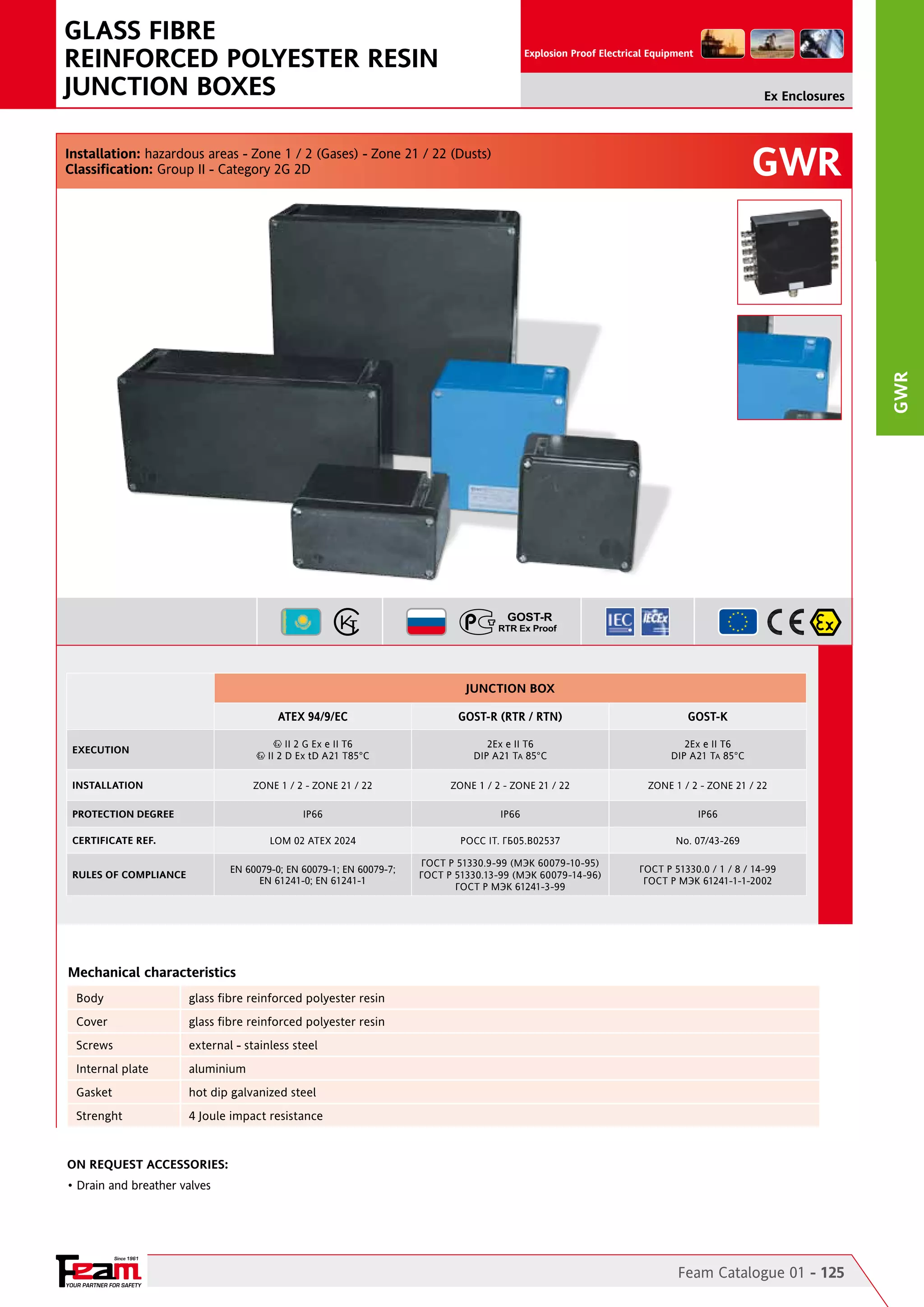
![Ex Enclosures
GWR Technical Features
CODE
A
[mm]
B
[mm]
C
[mm]
GWR11N
110
110
GWR14N
140
GWR21(1)
175
GWR22(1)
175
175
120
GWR42(1)
360
175
120
GWR44(1)
360
360
120
GWR84(1)
730
360
D
[mm]
166
E
[mm]
F
[mm]
G
[mm]
INT. PLATE
X - Y [mm]
102
53
H
[mm]
102
-
84
96
96
140
84
124
124
53
132
132
87,5
120
123
72
88
165
77,5
162
123
88
165
165
308
162
88
352
165
346
308
88
352
352
670
340
120
720
350
WEIGHT
[Kg]
DETAIL
0,30
A
-
0,40
A
-
0,88
A
135 - 135
1,25
A
320 - 135
2,50
A
320 - 320
3,40
A
670 - 310
8,00
A
(1) ENCLOSURE’S COLOUR: N = DARK GREY RAL7021 - B = LIGHT BLUE RAL5015 / EXAMPLE: GWR14N = COLOUR DARK GREY RAL 7021 GWR42B = COLOUR LIGHT BLUE RAL5015
A
Reference Details
wall DRILLING AREA
B
B
A
C
C
D
F
D
PLATE
X-Y
NON APRIRE SOTTO TENSIONE - DO NOT OPEN WHILE ENERGIZED
A
GxH
GWR
Reference Details
E
GWR Body Enclosures Drilling Layout
GWR11
64 x 52
QUANTITY ALLOWED ENTRIES FOR
SIZE (from 1 to size 8)
1
2
3
4
5
6
7
8
1 1
1
1
- -
-
-
64 x 52
QUANTITY ALLOWED ENTRIES FOR
SIZE (from 1 to size 8)
1
2
3
4
5
6
7
8
1
1
1 1
-
-
-
-
GWR14
90 X 52
2
1
1
1
-
-
-
-
90 X 52
2
GWR21
108 - 85
4
2
2
2
1
1
1
-
37 - 85
2
-
-
-
-
GWR22
108 - 85
4
2
2
2
1
1
1
-
108 - 85
4
2
2
2
1
GWR42
278 - 85
12
7
5
5
4
3
2
-
125 - 85
5
3
2
2
1
GWR44
310 - 85
12
8
7
5
4
4
3
-
125 - 85
5
3
2
2
1
GWR84
640 - 115
35 23
20
17
13
9
7
5
310 - 115
17
11
9
8
6
ENCLOSURE
CODE
DRILLING AREA
A-B [mm]
DRILLING AREA
A-B [mm]
1
1
1
-
-
-
-
-
-
-
1
1
-
1
1
-
1
1
-
4
3
2
gwr Indicative quantity of terminals and relevant section
CODE
ENCLOSURE
SECT. 2,5
[mm/sq]
SECT. 6,0
[mm/sq]
SECT. 10,0
[mm/sq]
SECT. 16,0
[mm/sq]
SECT. 35,0
[mm/sq]
SECT. 50,0
[mm/sq]
SECT. 70,0
[mm/sq]
SECT.240,0
[mm/sq]
INT.PLATE X - Y
[mm]
GWR11
12 x 1
8x1
6x1
5x1
3x1
3x1
1x1
1x1
-
GWR14
18 x 1
10 x 1
8x1
7x1
5x1
4x1
2x1
1x1
-
GWR21
18 x 1
10 x 1
8x1
7x1
5x1
4x1
2x1
1x1
-
GWR22
20 x 1
10 x 1
10 x 1
6x1
6x1
4x1
2x1
1x1
135 - 135
GWR42
48 x 1
28 x 1
24 x 1
20 x 1
12 x 1
10 x 1
4x1
2x1
320 - 135
GWR44
48 x 2
28 x 2
24 x 2
20 x 2
12 x 2
10 x 2
8x1
4x1
320 - 320
GWR84
120 x 2
70 x 2
60 x 2
50 x 2
44 x 2
30 x 2
20 x 1
14 x 1
670 - 310
REMARK: Due to the development of the national and international specifications and of the technology, the above technical characteristics
showed on this bulletin can be considered as binding on our confirmation only.
Since 1961
126 - Feam Catalogue 01
YOUR PARTNER FOR SAFETY](https://image.slidesharecdn.com/a-131107095443-phpapp01/75/FEAM-Enclosures-Hazardous-Area-Explosion-Proof-Enclosures-ATEX-IECEx-Inmetro-GOST-R-GOST-K-NEC505-32-2048.jpg)
![GRP and STAINLESS STEEL
Ex-de PUSH BUTTON STATIONS
Explosion Proof Electrical Equipment
Ex Enclosures
GWRCS - ESX
GWRCS - ESX
Installation: hazardous areas - Zone 1 / 2 (Gases) - Zone 21 / 22 (Dusts)
Classification: Group II - Category 2G 2D
JUNCTION BOX FOR CONTROL. SWITCHGEAR and SIGNALLING - GWRCS
ATEX 94/9/EC
GOST-R (RTR / RTN)
GOST-K
2Ex ed IIC T6
DIP A21 TA 85°C
2Ex ed IIC T6
DIP A21 TA 85°C
ZONE 1 / 2 - ZONE 21 / 22
ZONE 1 / 2 - ZONE 21 / 22
ZONE 1 / 2 - ZONE 21 / 22
IP66
IP66
IP66
LOM 02 ATEX 2024
POCC IT. ГБ05.B02537
No. 07/43-269
EN 60079-0; EN 60079-1;
EN 60079-7; EN 61241-0;
EN 61241-1
ГОСТ Р 51330.9-99 (МЭК 60079-10-95)
ГОСТ Р 51330.13-99 (МЭК 60079-14-96)
ГОСТ Р МЭК 61241-3-99
ГОСТ Р 51330.0 / 1 / 8 / 14-99
ГОСТ Р МЭК 61241-1-1-2002
II 2 G Ex ed IIC T6
II 2 D Ex tD A21 T85°C
EXECUTION
INSTALLATION
PROTECTION DEGREE
CERTIFICATE REF.
RULES OF COMPLIANCE
JUNCTION BOX FOR CONTROL. SWITCHGEAR and SIGNALLING - ESX
ATEX 94/9/EC
GOST-R (RTR / RTN)
GOST-K
2Ex e II T5 X, 0Ex ia IIB/IIC T4…T6 X,
2Ex e [ia] IIB/IIC T4, T5 X
DIP A21 TA 100°C
2Ex e II T5 X, 0Ex ia IIB/IIC T4…T6 X,
2Ex e [ia] IIB/IIC T4, T5 X
DIP A21 TA 100°C
-50°C ÷ +175°C
-50°C ÷ +175°C
-50°C ÷ +175°C
IP66
IP66
IP66
INERIS 02 ATEX 0067X
POCC IT. ГБ05.B02537
No. 07/43-269
EN 60079-0; EN 60079-7;
EN 60079-11; 61241-1
ГОСТ Р 51330.9-99 (МЭК 60079-10-95)
ГОСТ Р 51330.13-99 (МЭК 60079-14-96)
ГОСТ Р МЭК 61241-3-99
ГОСТ Р 51330.0 / 1 / 8 / 14-99
ГОСТ Р МЭК 61241-1-1-2002
II 2 G Ex e II T5
II 2 G Ex e [ia] IIB/IIC T5
II 2 D Ex tD A21 T100°C
EXECUTION
AMBIENT TEMPERATURE
PROTECTION DEGREE
CERTIFICATE REF.
RULES OF COMPLIANCE
Mechanical characteristics - GWRCS
Mechanical characteristics - ESX
Body
glass fibre reinforced polyester resin color dark grey RAL 7021
Body
stainless steel AISI 316l sp. 1,5mm
Cover
glass fibre reinforced polyester resin color dark grey RAL 7021
Cover
stainless steel AISI 316l sp. 1,5mm
Screws
stainless steel
Screws
stainless steel AISI 316L
Internal plate
stainless steel - aluminium
Internal plate
stainless steel AISI 316L
Gasket
silicon
Gasket
silicon
Strenght
4 Joule impact resistance
Strenght
4 Joule di resistenza all'urto
On Request Accessories:
• External epoxy painting with colour on request
• Internal anticondensate painting orange RAL 2004 (ESX)
• Drain and breather valves
• Removable flanges (only stainless steel enclosures)
Since 1961
YOUR PARTNER FOR SAFETY
Feam Catalogue 01 - 127](https://image.slidesharecdn.com/a-131107095443-phpapp01/75/FEAM-Enclosures-Hazardous-Area-Explosion-Proof-Enclosures-ATEX-IECEx-Inmetro-GOST-R-GOST-K-NEC505-33-2048.jpg)
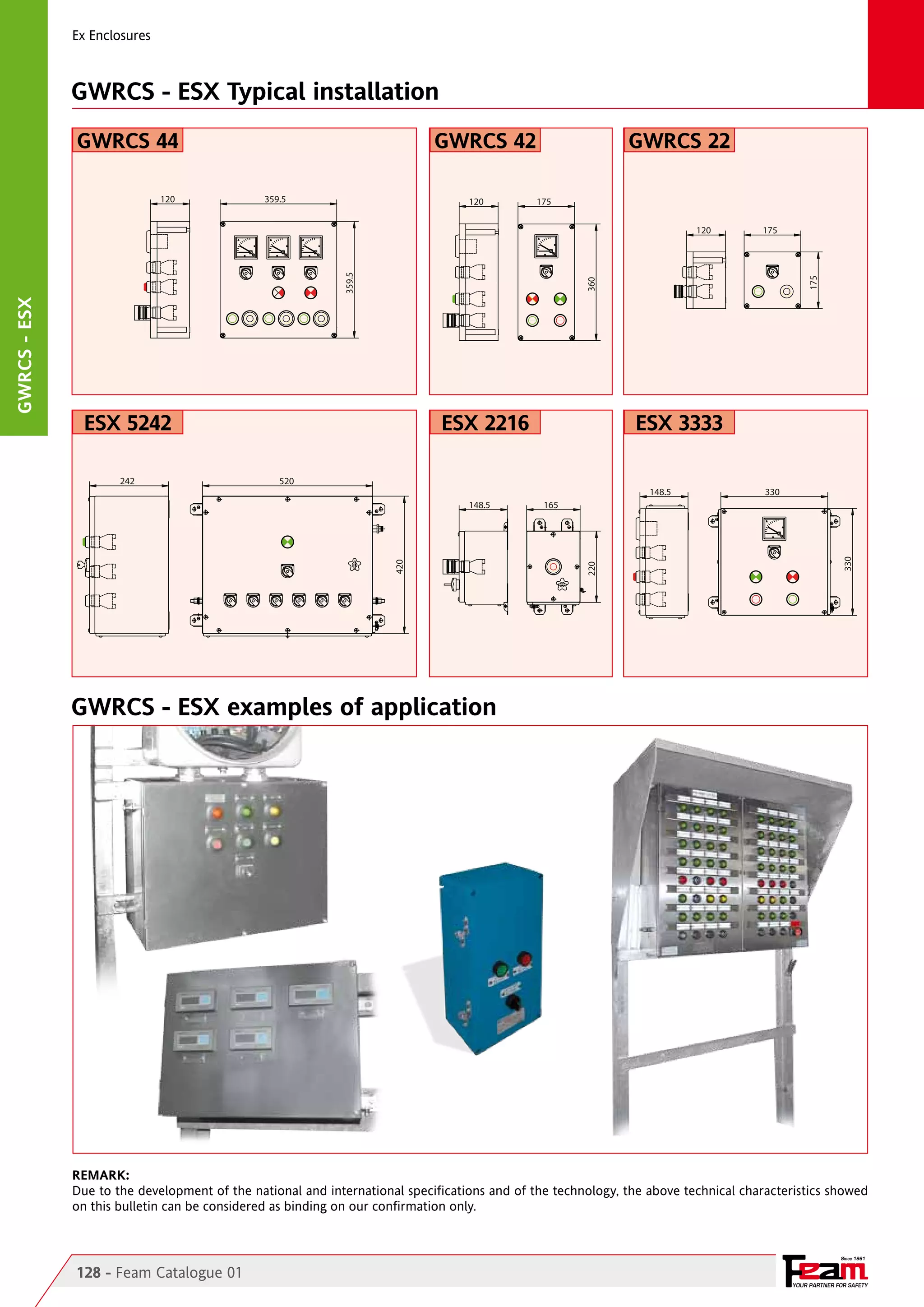
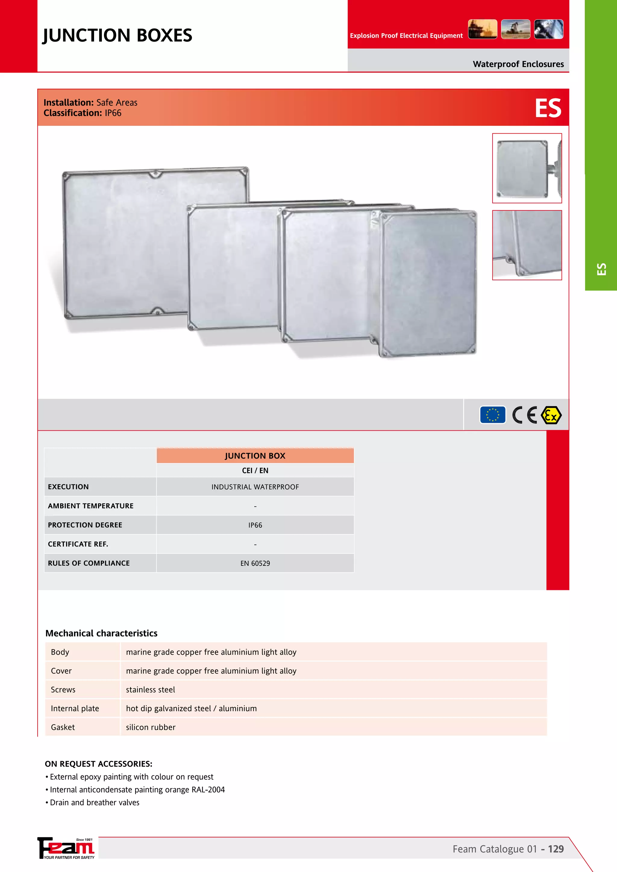
![Waterproof Enclosures
ES Technical Features
A
[mm]
B
[mm]
ES1313
130
130
85
ES1717
170
170
95
ES2216
220
160
95
205
ES2222
220
220
110
205
ES3322
330
220
120
312
ES3333
330
330
130
310
ES4433
440
330
150
420
CODE
C
[mm]
D
[mm]
E
[mm]
F
[mm]
G
[mm]
H
[mm]
INT.PLATE
X - Y [mm]
WEIGHT
[Kg]
DETAIL
115
115
71
114
155
155
81
154
114
112 - 70
1,20
A
154
150 - 150
1,50
A
145
81
204
144
205
97
204
204
200 - 100
3,80
A
200 - 160
4,40
A
202
103
316
310
114
316
206
294 - 154
6,40
A
316
290 - 290
8,80
A
310
155
426
316
400 - 290
11,40
A
ES5242
520
420
180
496
396
165
506
406
460 - 370
20,20
A
ES6348
630
480
180
610
460
165
598
466
550 - 400
21,30
A
Reference Details
A
wall DRILLING AREA
C
B
A
PLATE X-Y
A
DxE
B
GxH
F
D
ES
Reference Details
C
ES Body Enclosures Drilling Layout
ENCLOSURE
CODE
DRILLING AREA
A-B [mm]
QUANTITY ALLOWED ENTRIES FOR
SIZE (from 1 to size 8)
1
2
3
4
5
6
7
8
2
1
1
1
/
/
/
/
DRILLING AREA
C-D [mm]
QUANTITY ALLOWED ENTRIES FOR
SIZE (from 1 to size 8)
1
2
3
4
5
6
7
8
2
1
1 1
/
/
/
/
ES1313
88 x55
88 x55
ES1717
150 x 70
5
3
2
2
2
1
/
/
150 x 70
5
3
2
2
2
1
/
/
ES2216
200 x 70
6
3
3
3
2
2
/
/
120 x 70
4
2
2
2
1
1
/
/
ES2222
200 x 85
8
5
3
3
3
2
2
/
200 x 85
8
5
3
3
3
2
2
/
ES3322
285 x 90
12
7
6
5
4
3
3
/
200 x 90
8
5
4
4
3
2
2
/
ES3333
275 x 90
12
7
6
5
4
3
2
/
275 x 90
12
7
6
5
4
3
2
/
ES4433
370 x 110
20
14
12
12
6
5
3
/
265 x 110
14
10
8
8
4
3
2
/
ES5242
420 x 145
30
18
16
12
12
8
4
2
360 x 145
28
18
14 11
10
7
4
3
ES6348
500 x 140
36
24
18
16
12
10
6
4
400 x 140
30
21
15 12
10
8
4
3
ES Indicative quantity of terminals and relevant section
CODE
ENCLOSURE
SECT. 2,5
[mm/sq]
SECT. 6,0
[mm/sq]
SECT. 10,0
[mm/sq]
SECT. 16,0
[mm/sq]
SECT. 35,0
[mm/sq]
SECT. 50,0
[mm/sq]
SECT. 70,0
[mm/sq]
SECT. 240,0
[mm/sq]
INT.PLATE X - Y
[mm]
ES1313
10 x 1
5x1
4x1
4x1
3x1
2x1
1x1
/
112 - 70
ES1717
20 x 1
10 x 1
8x1
8x1
6x1
3x1
2x1
1x1
150 - 150
ES2216
30 x 1
18 x 1
14 x 1
10 x 1
8x1
3x1
2x1
1x1
200 - 200
ES2222
26 x 1
16 x 1
12 x 1
10 x 1
8x1
4x1
2x1
2x1
200 - 160
ES3322
46 x 1
26 x 1
22 x 1
18 x 1
14 x 1
10 x 1
6x1
2x1
294 - 154
ES3333
46 x 2
24 x 2
22 x 2
16 x 2
14 x 2
10 x 1
8x1
3x1
290 - 290
ES4433
70 x 2
40 x 2
32 x 2
26 x 2
20 x 2
14 x 2
10 x 1
4x1
400 - 290
ES5242
70 x 3
44 x 3
34 x 3
30 x 3
22 x 3
18 x 2
14 x 1
6x1
460 - 370
ES6348
120 x 3
76 x 3
60 x 3
50 x 3
34 x 3
30 x 2
24 x 1
12 x 1
685 - 340
REMARK: Due to the development of the national and international specifications and of the technology, the above technical characteristics
showed on this bulletin can be considered as binding on our confirmation only.
Since 1961
130 - Feam Catalogue 01
YOUR PARTNER FOR SAFETY](https://image.slidesharecdn.com/a-131107095443-phpapp01/75/FEAM-Enclosures-Hazardous-Area-Explosion-Proof-Enclosures-ATEX-IECEx-Inmetro-GOST-R-GOST-K-NEC505-36-2048.jpg)

The document details the specifications and features of custom-designed switchracks and electrical equipment suitable for hazardous areas, complying with various international standards. It outlines the installation requirements, technical characteristics, and various configurations available for switchracks and enclosures, including inspection and testing protocols. Additionally, it highlights the long-standing experience of the manufacturer, FEAM, in providing safety equipment since 1961.


![Coded Agents – with UiPath SDK + LangGraph [Virtual Hands-on Workshop]](https://cdn.slidesharecdn.com/ss_thumbnails/codedagentsdeck-251215155422-5497c599-thumbnail.jpg?width=640&height=640&fit=bounds)


