Downloaded 50 times


![ELASTIMOLD
®
CATALOG 2001x
Issue Date: 01/98
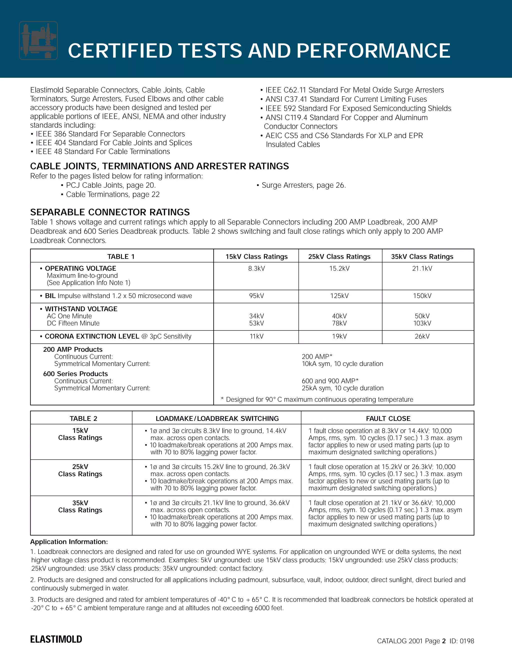
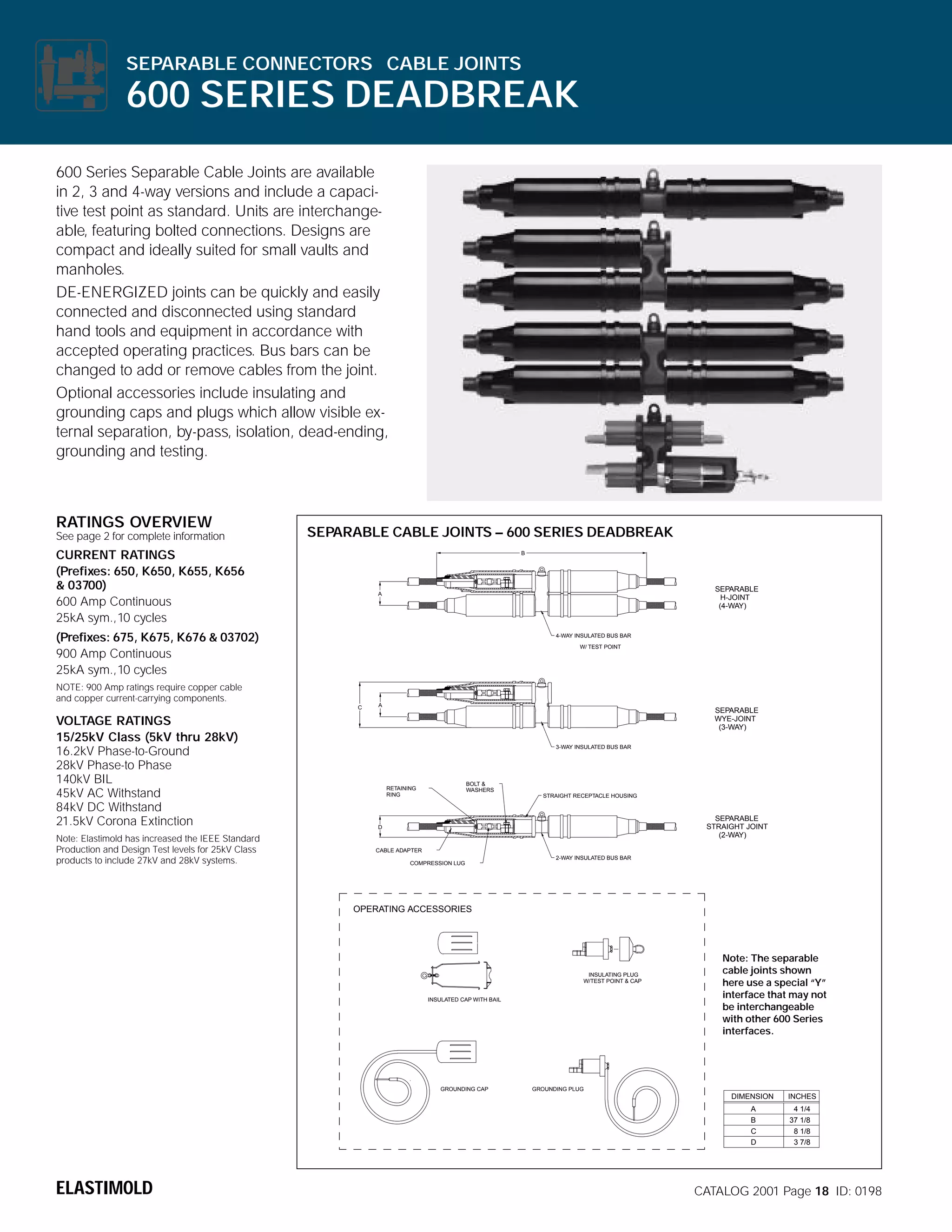
SEPARABLE CONNECTORS
•
CABLE JOINTS
]
TERMINATIONS
SURGE ARRESTERS
FUSES
LOADBREAK SWITCHES
For 5kV-35kV Distribution Systems](https://image.slidesharecdn.com/elastimold-140130102426-phpapp02/75/Elastimold-Connectors-Loadbreak-Deadbreak-Elbow-Bolted-Tee-Connectors-HV-MV-700-Series-37-2048.jpg)

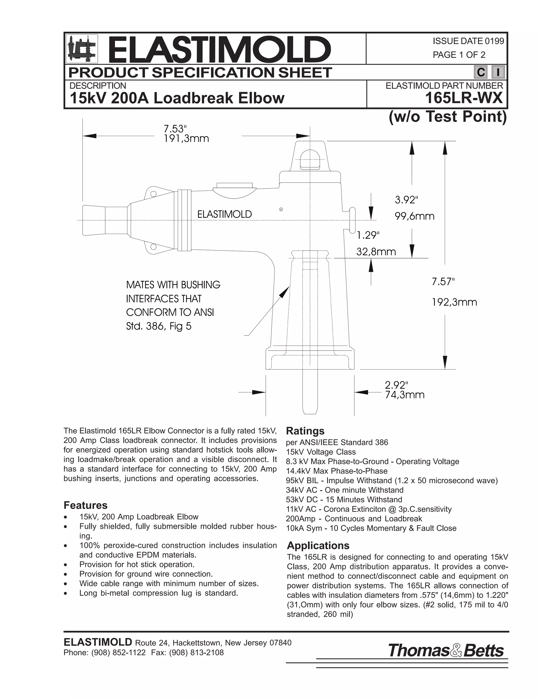


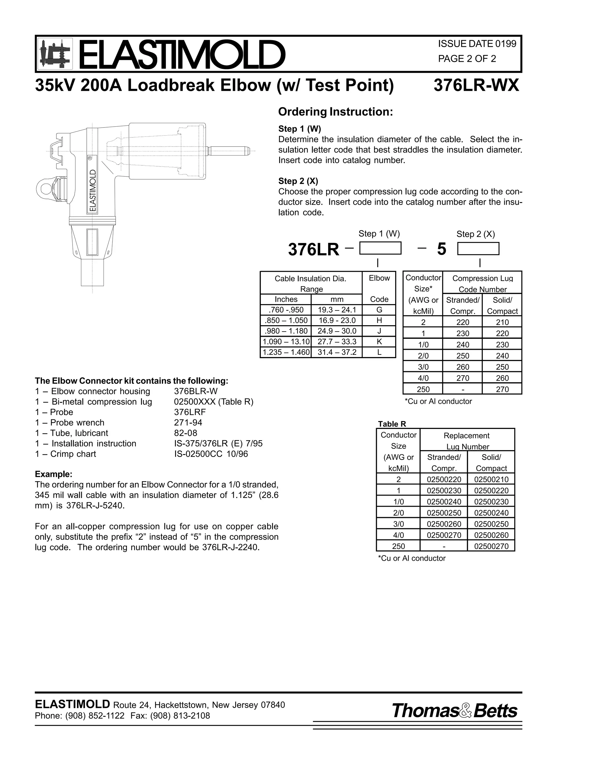

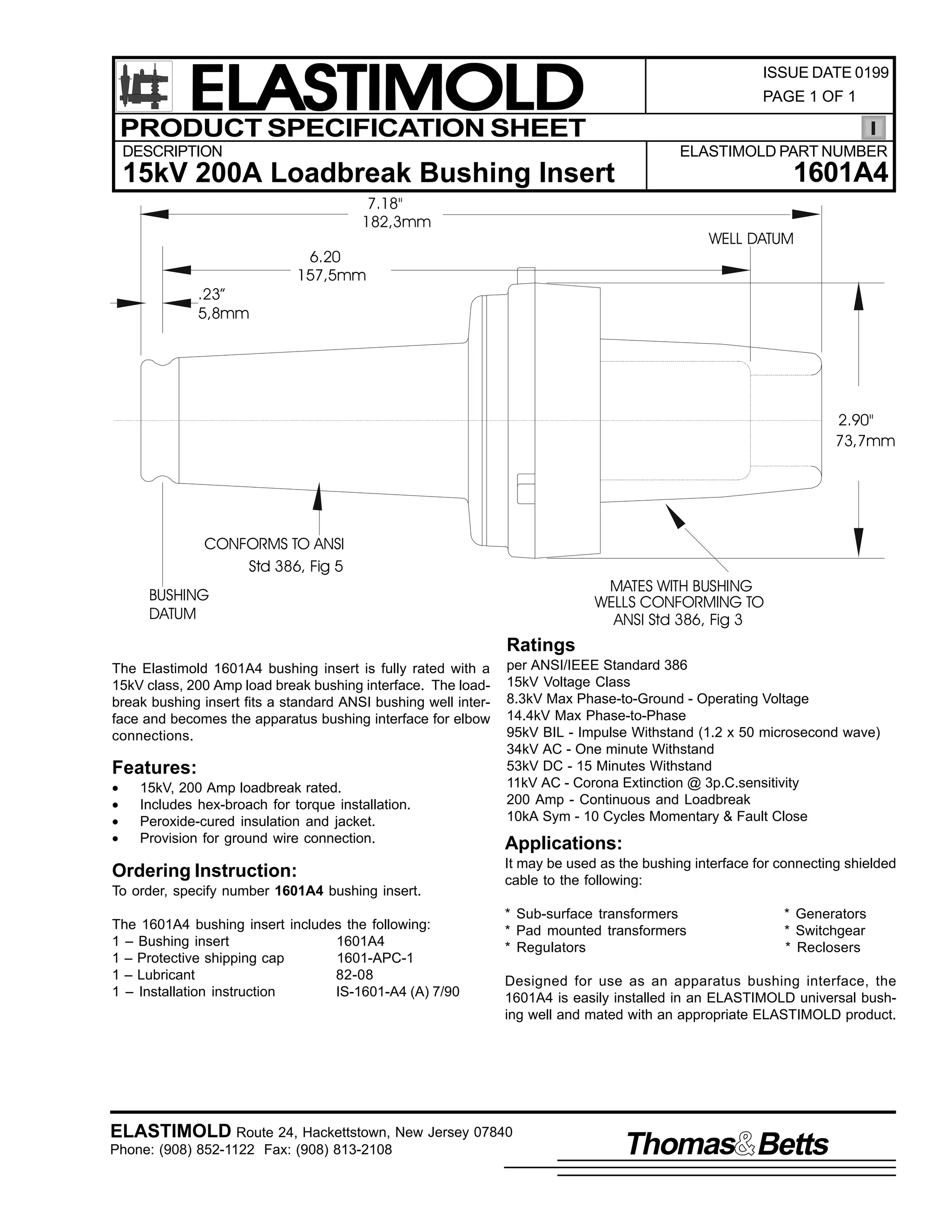
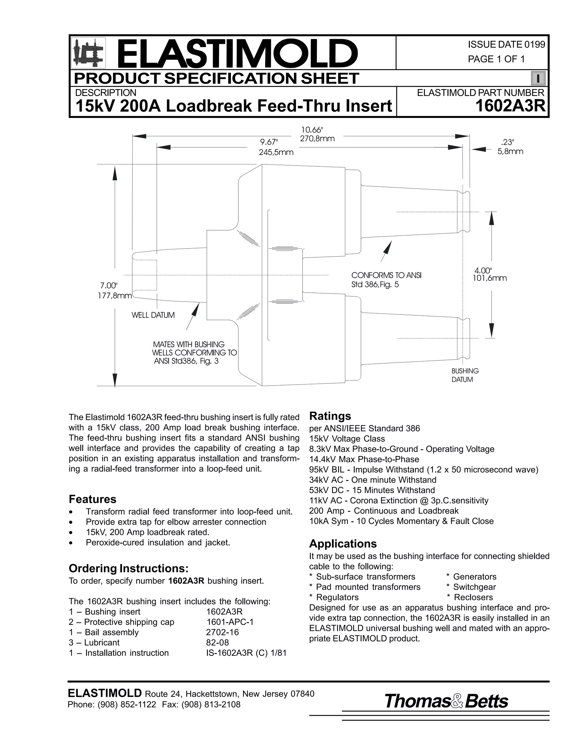
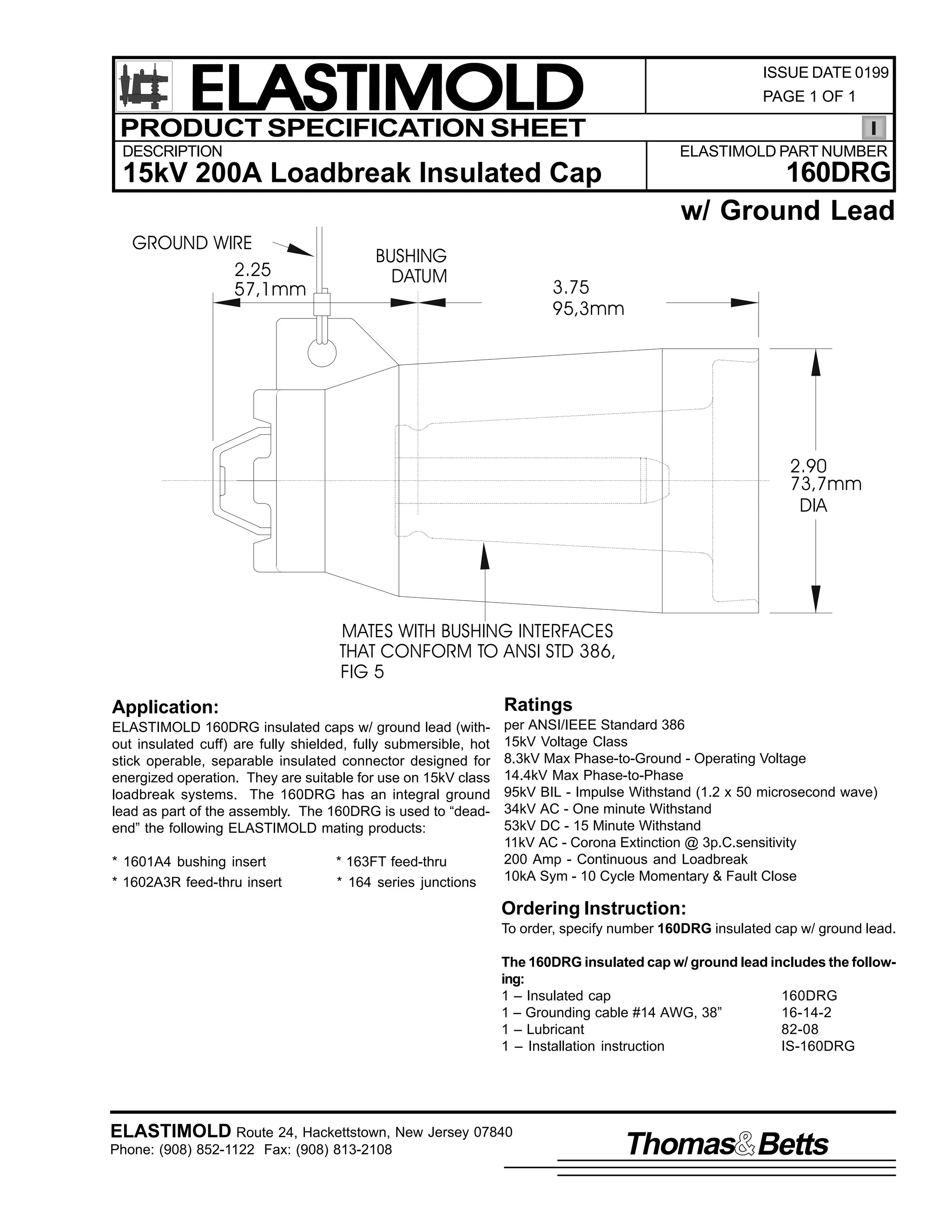
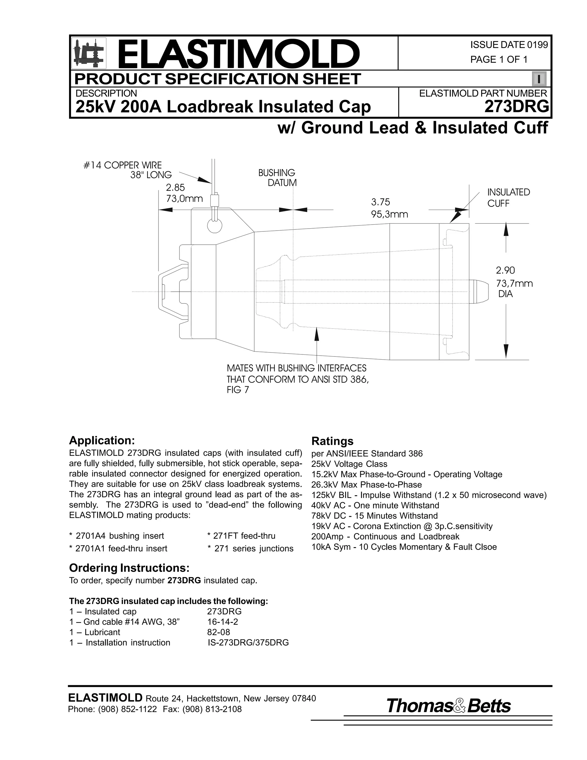
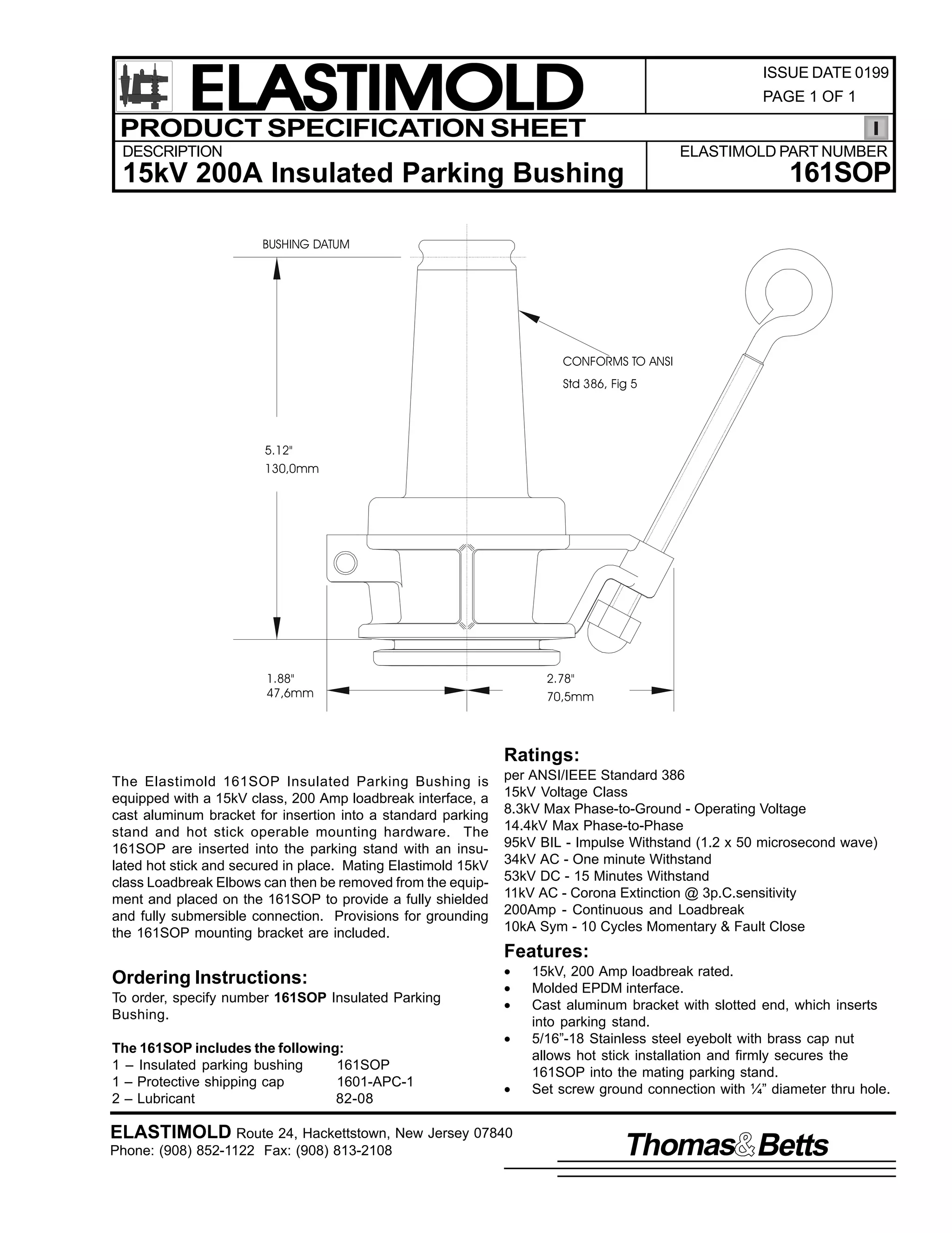
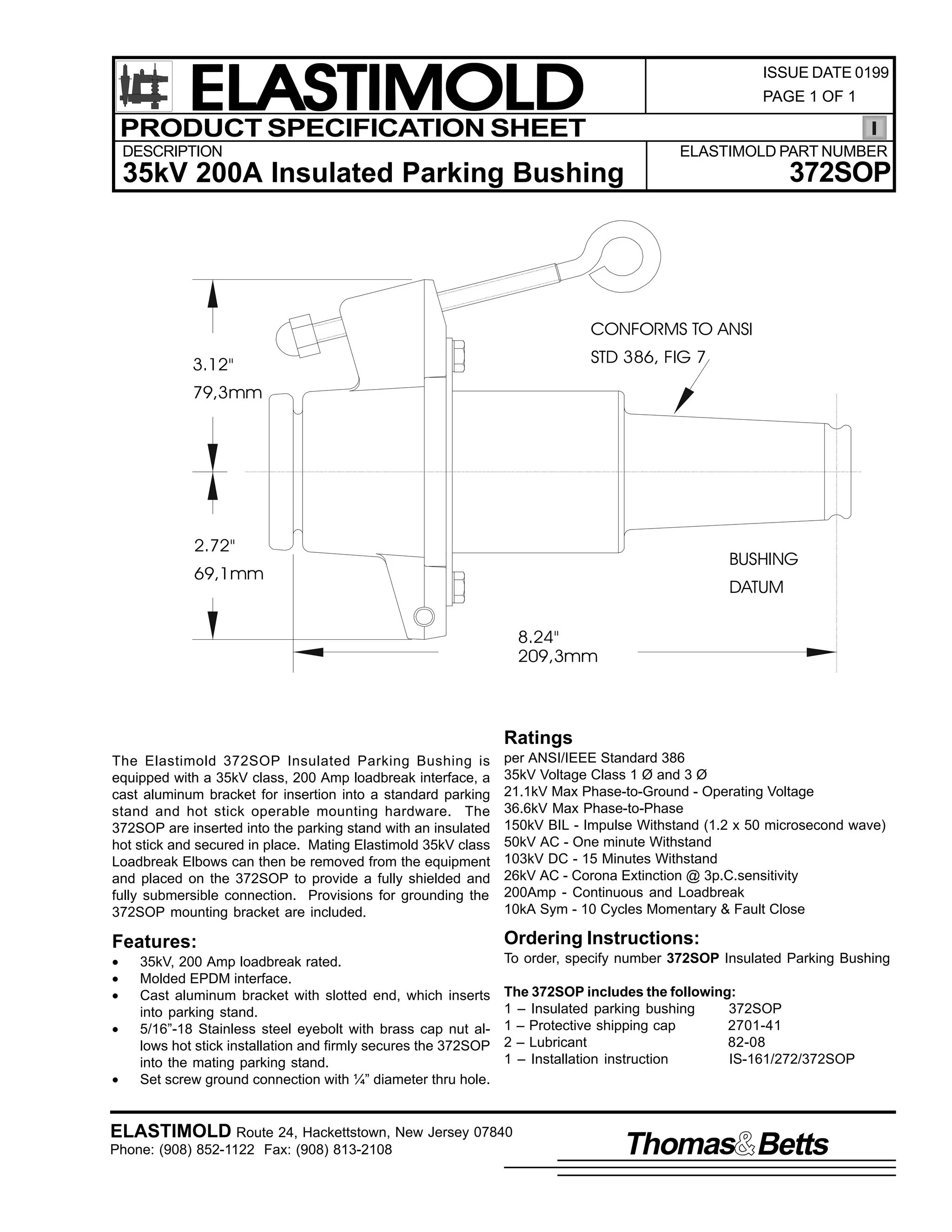
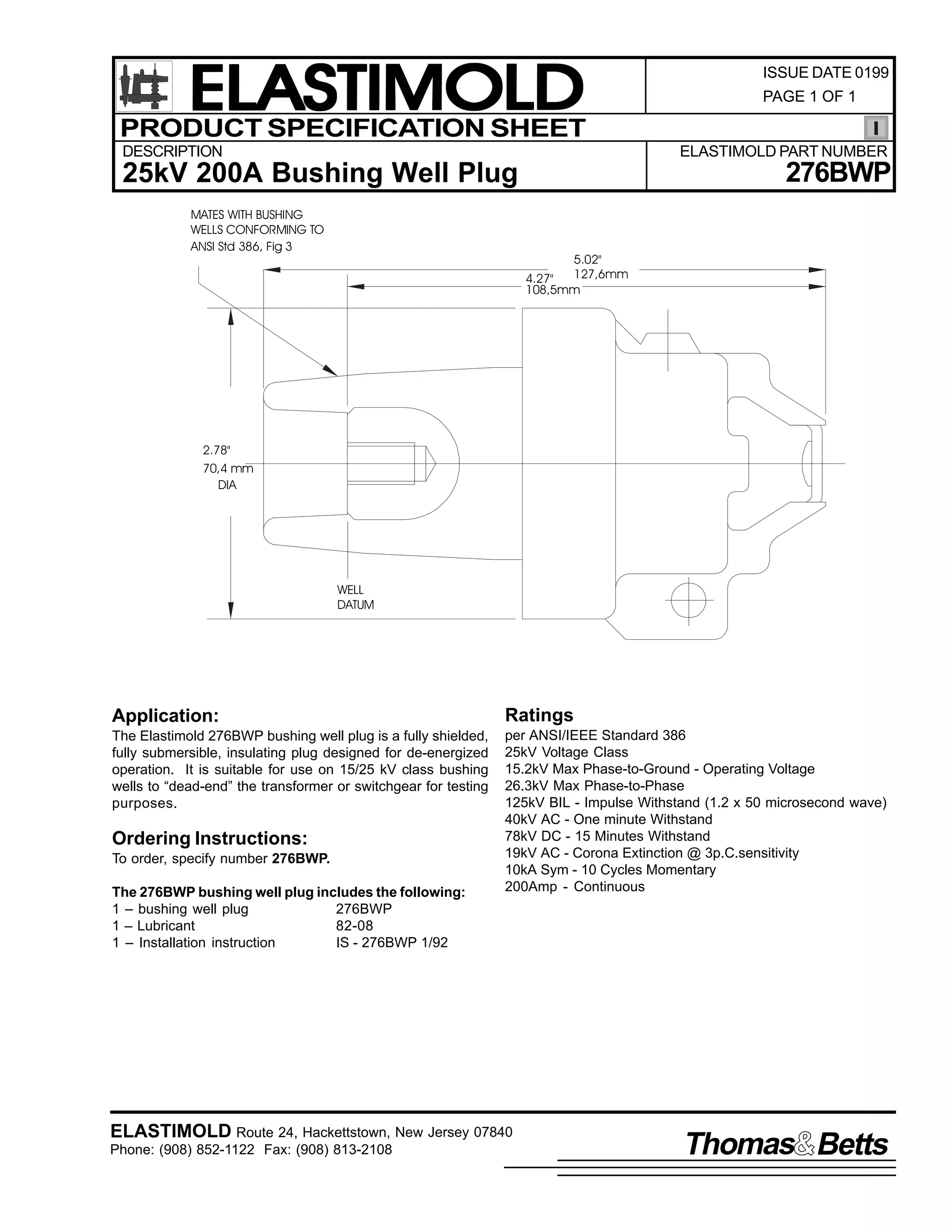
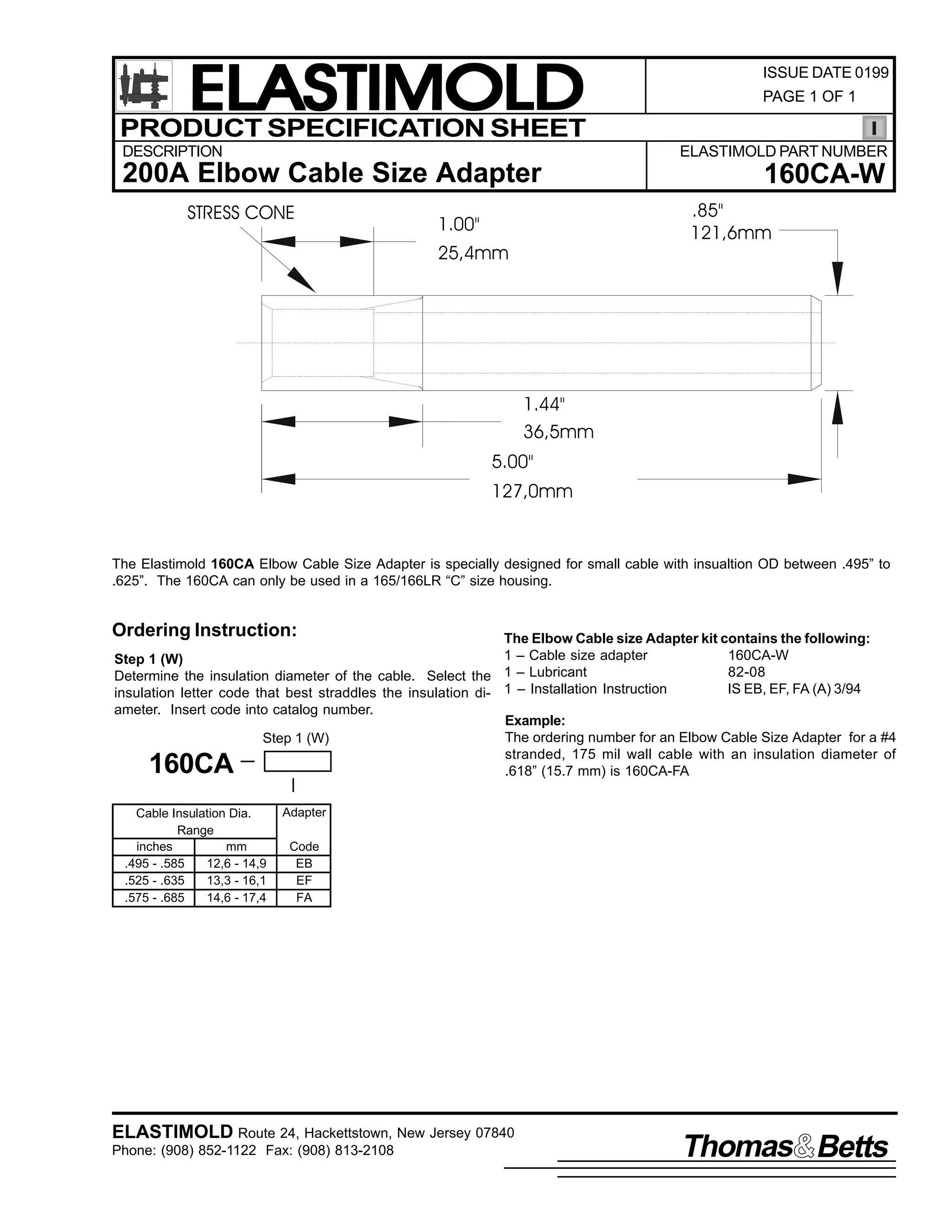
![ELASTIMOLD
PRODUCT SPECIFICATION SHEET
ISSUE DATE 0199
PAGE 1 OF 2
C
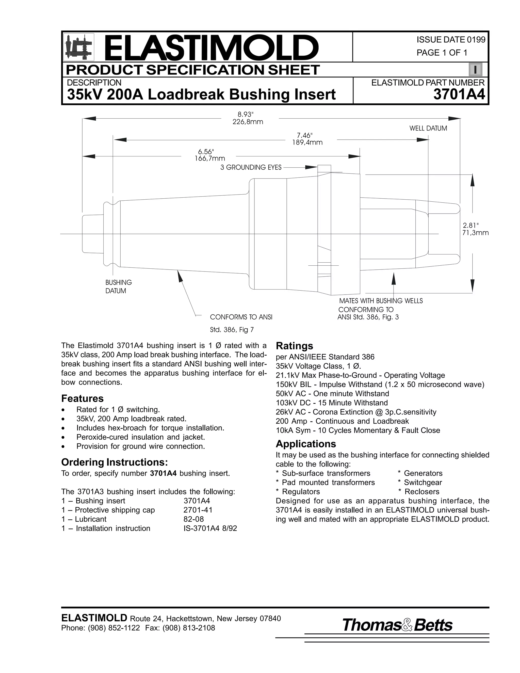
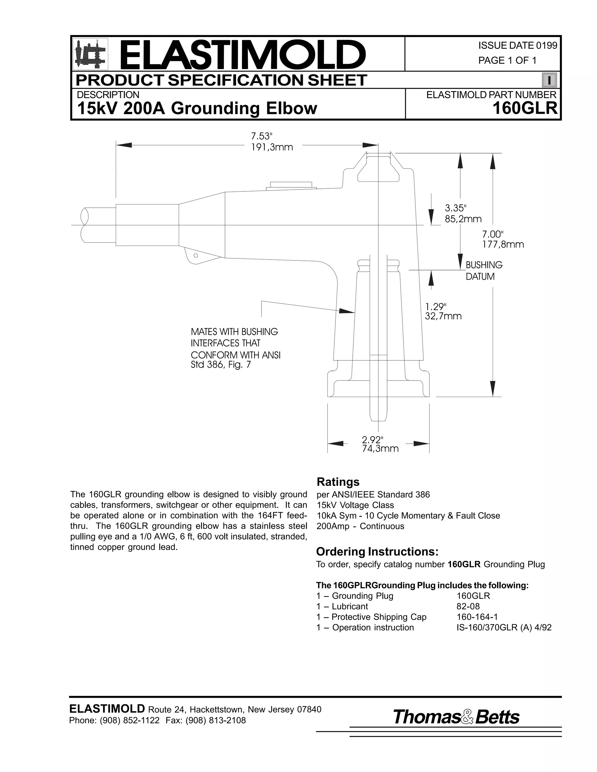
DESCRIPTION
ELASTIMOLD PART NUMBER
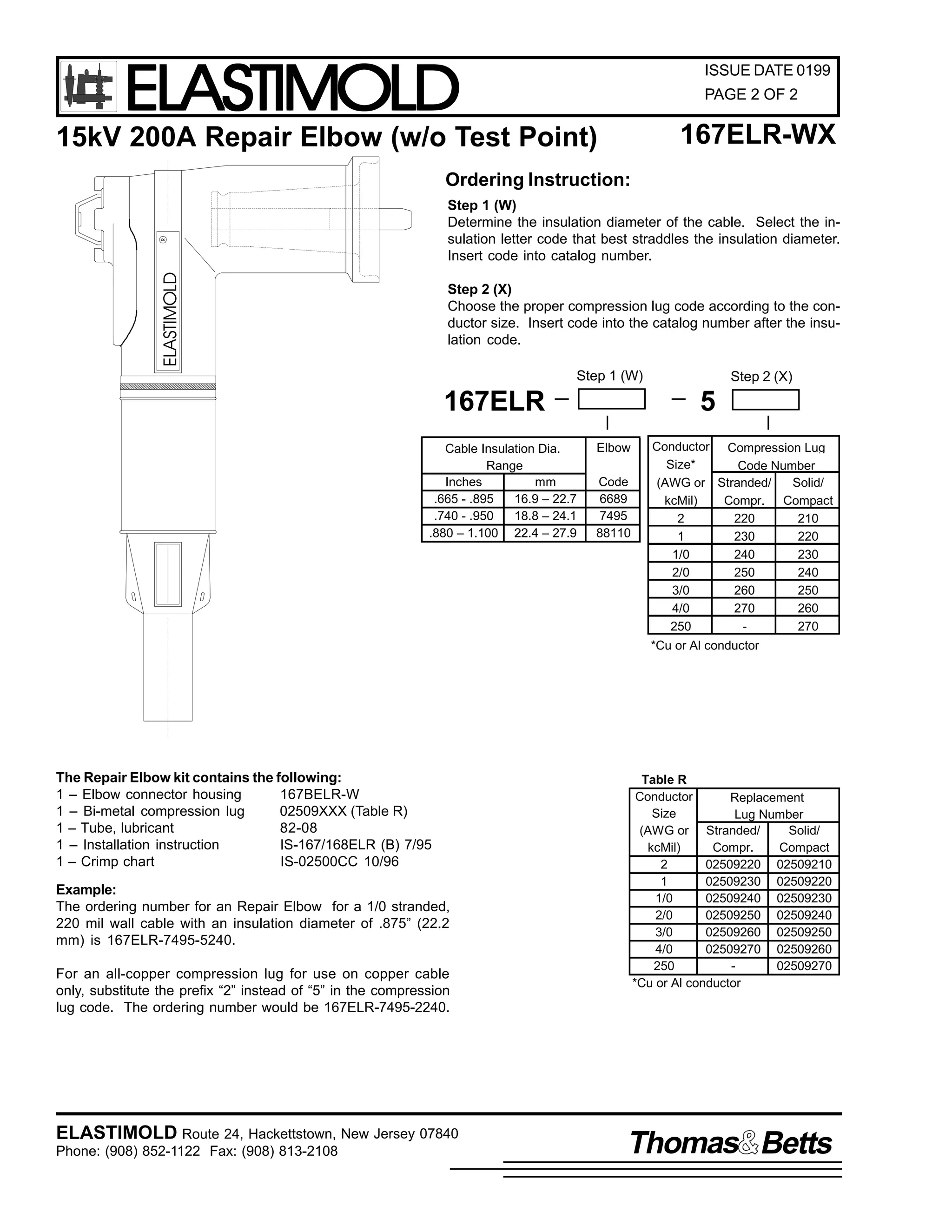
167ELR-WX
(w/o Test Point)
15kV 200A Repair Elbow
11.71"
297,0mm
ELASTIMOLD
R
3.56"
90,4mm
1.31"
33,3mm
MATES WITH BUSHING
INTERFACES THAT
CONFORM TO ANSI
Std 386, Fig 5
7.10"
180,0mm
2.93"
74,2mm
Ratings
The Elastimold 167ELR Repair Elbow is a fully rated 15kV
Class loadbreak elbow connector with a lengthened compression lug and housing. The Repair Elbow accommodates
cables that are too short to be connected to a standard elbow.
Features
•
•
•
•
Extended length housing and compression lug
[ + 3-1/4" (82,6mm)].
15kV, 200A Loadbreak Elbow Connector.
Fully shielded, fully submersible molded rubber housing.
Peroxide-cured insulation, insert and jacket.
NOTE: For housing extension greater than 3-1/4" (82,6mm),
refer to Elastimold Part number 167RLR.
per ANSI/IEEE Standard 386
15kV Voltage Class
8.3 kV Max Phase-to-Ground - Operating Voltage
14.4kV Max Phase-to-Phase
95kV BIL - Impulse Withstand (1.2 x 50 microsecond wave)
34kV AC - One minute Withstand
53kV DC - 15 Minutes Withstand
11kV AC - Corona Extinciton @ 3p.C.sensitivity
200Amp - Continuous and Loadbreak
10kA Sym - 10 Cycles Momentary & Fault Clsoe
Applications
The 167ELR is designed for connecting to and operating 15kV
Class, 95kV BIL distribution apparatus. Typical uses for the
special characteristics of the 167ELR Repair Elbow includes
the following:
•
Repair of a failed elbow connection where the cable must
be stripped back and a new compression lug applied.
•
To gain extra length when cables have been accidentally
trimmed too short or to connect new apparatus to existing
cables.
ELASTIMOLD Route 24, Hackettstown, New Jersey 07840
Phone: (908) 852-1122 Fax: (908) 813-2108
Thomas Betts](https://image.slidesharecdn.com/elastimold-140130102426-phpapp02/75/Elastimold-Connectors-Loadbreak-Deadbreak-Elbow-Bolted-Tee-Connectors-HV-MV-700-Series-65-2048.jpg)
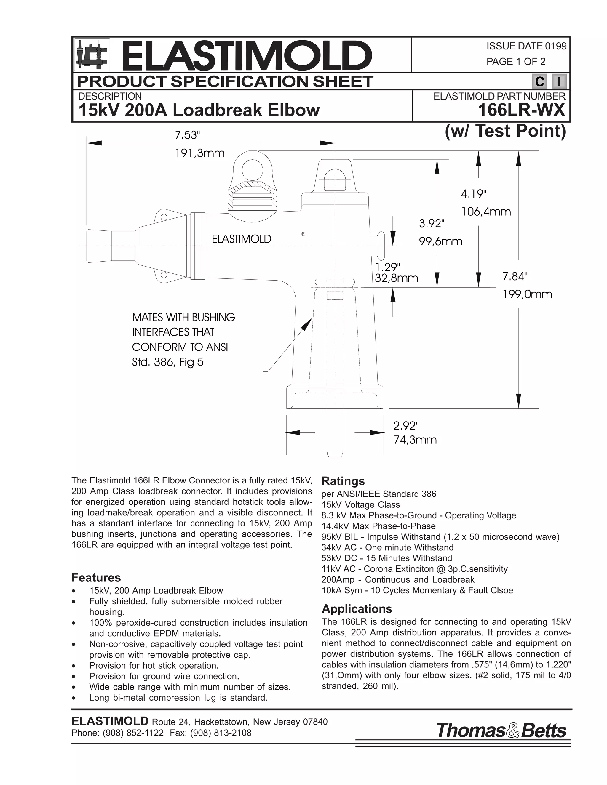
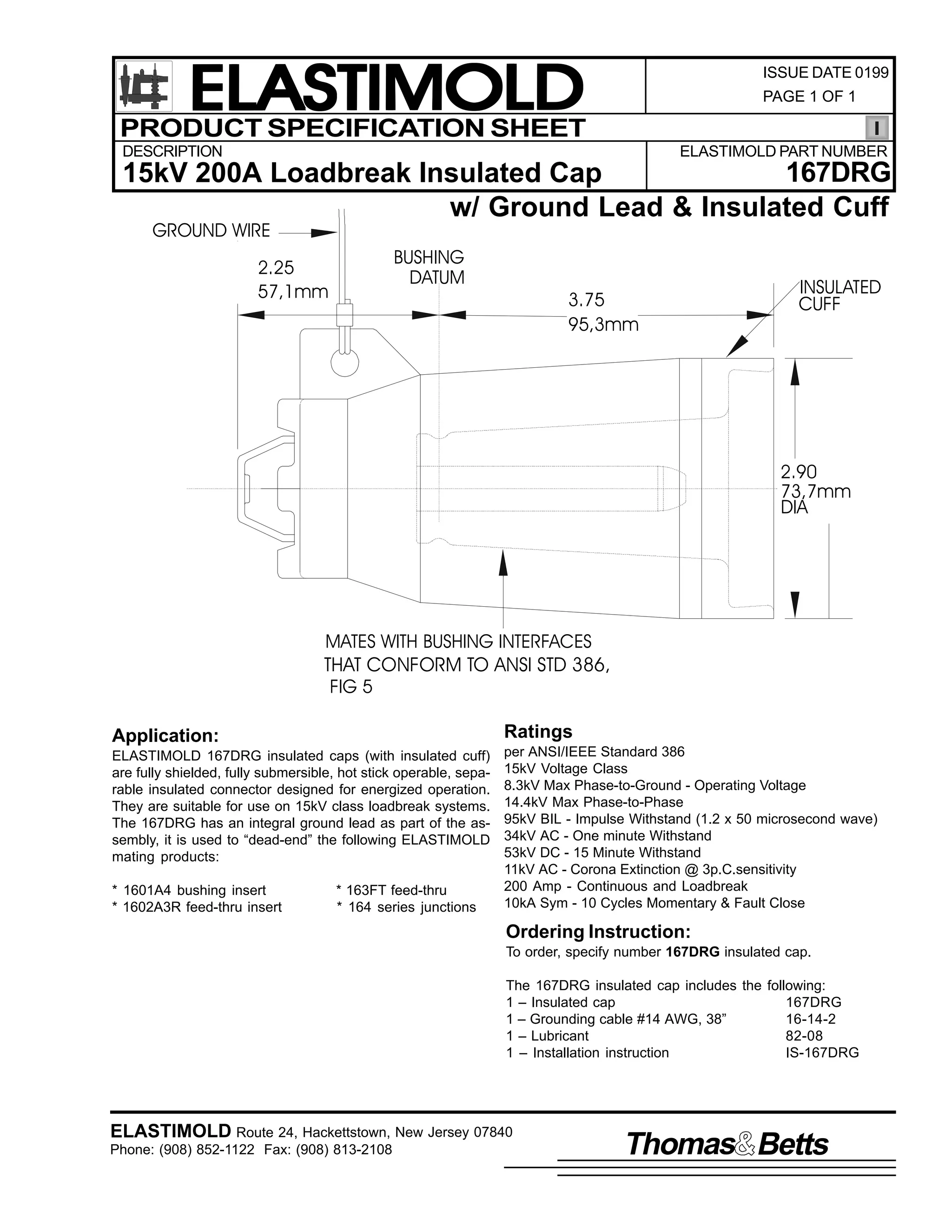
![ELASTIMOLD
PRODUCT SPECIFICATION SHEET
ISSUE DATE 0199
PAGE 1 OF 2
C
DESCRIPTION
ELASTIMOLD PART NUMBER
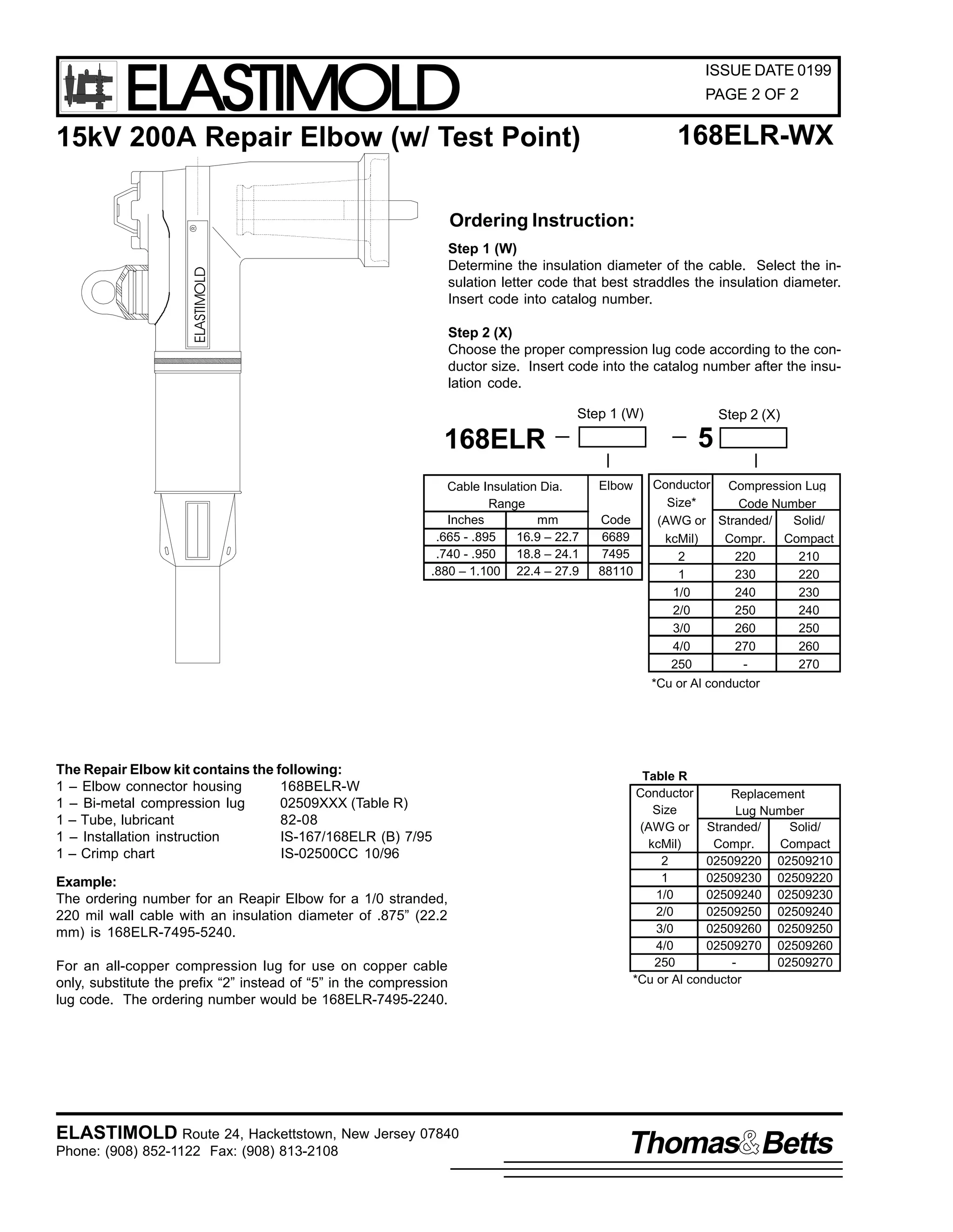
168ELR-WX
(w/ Test Point)
15kV 200A Repair Elbow
11.71"
297,0mm
ELASTIMOLD
3.56"
90,4mm
R
1.31"
33,3mm
4.30"
109,0mm
7.95"
202,0mm
MATES WITH BUSHING
INTERFACES THAT
CONFORM TO ANSI
Std 386, Fig 5
2.92"
74,3mm
Ratings
The Elastimold 168ELR Repair Elbow is a fully rated 15kV
Class loadbreak elbow connector with a lengthened compression lug and housing. The Repair Elbow accommodates
cables that are too short to be connected to a standard elbow.
Features
•
•
•
•
Extended length housing and compression lug
[ + 3-1/4" (82,6mm)].
15kV, 200A Loadbreak Elbow Connector.
Fully shielded, fully submersible molded rubber housing.
Peroxide-cured insulation, insert and jacket.
NOTE: For housing extension greater than 3-1/4" (82,6mm),
refer to Elastimold Part number 168RLR.
per ANSI/IEEE Standard 386
15kV Voltage Class
8.3 kV Max Phase-to-Ground - Operating Voltage
14.4kV Max Phase-to-Phase
95kV BIL - Impulse Withstand (1.2 x 50 microsecond wave)
34kV AC - One minute Withstand
53kV DC - 15 Minutes Withstand
11kV AC - Corona Extinciton @ 3p.C.sensitivity
200Amp - Continuous and Loadbreak
10kA Sym - 10 Cycles Momentary & Fault Clsoe
Applications
The 167ELR is designed for connecting to and operating 15kV
Class, 95kV BIL distribution apparatus. Typical uses for the
special characteristics of the 168ELR Repair Elbow includes
the following:
•
Repair of a failed elbow connection where the cable must
be stripped back and a new compression lug applied.
•
To gain extra length when cables have been accidentally
trimmed too short or to connect new apparatus to existing
cables.
ELASTIMOLD Route 24, Hackettstown, New Jersey 07840
Phone: (908) 852-1122 Fax: (908) 813-2108
Thomas Betts](https://image.slidesharecdn.com/elastimold-140130102426-phpapp02/75/Elastimold-Connectors-Loadbreak-Deadbreak-Elbow-Bolted-Tee-Connectors-HV-MV-700-Series-67-2048.jpg)

![ELASTIMOLD
PRODUCT SPECIFICATION SHEET
ISSUE DATE 0199
PAGE 1 OF 2
C
DESCRIPTION
ELASTIMOLD PART NUMBER
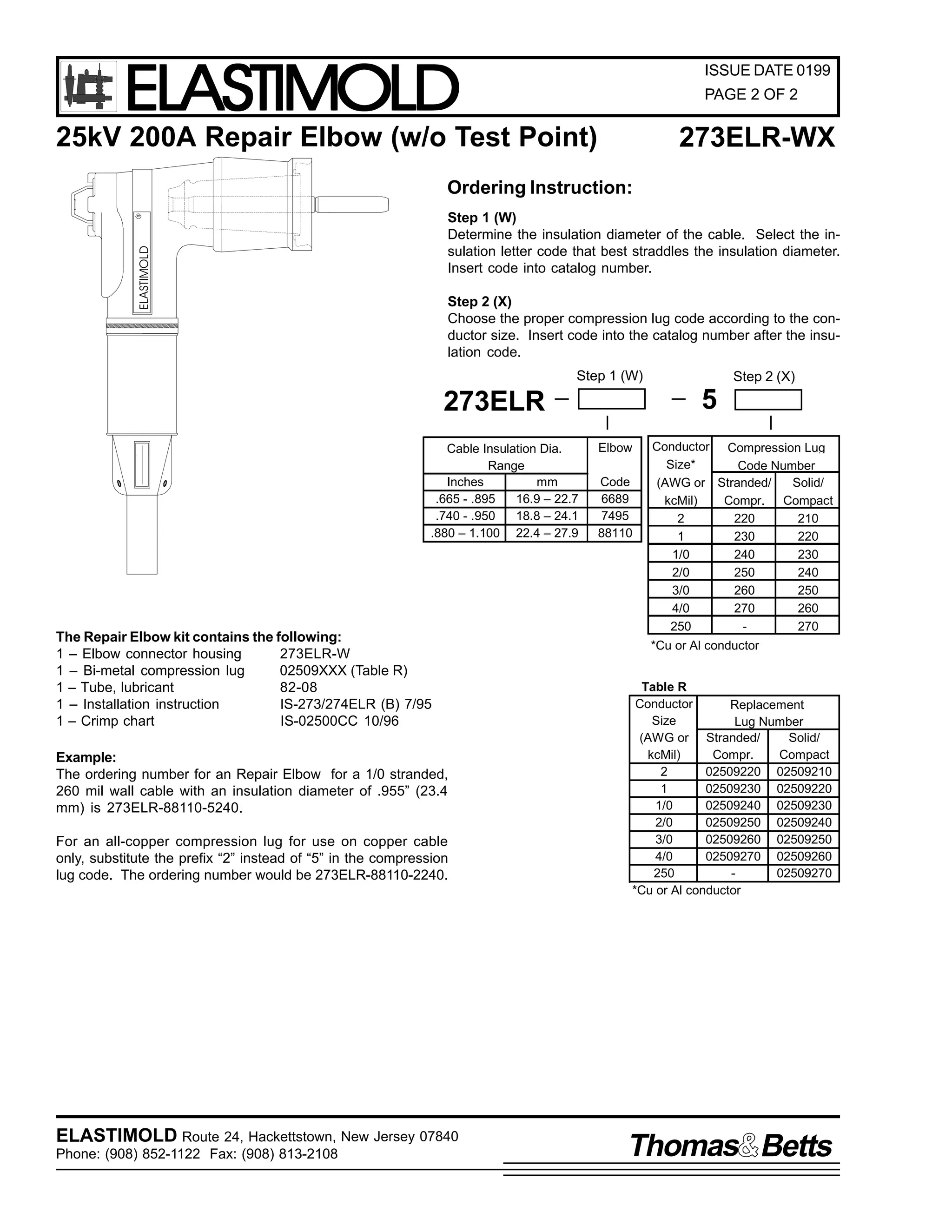
273ELR-WX
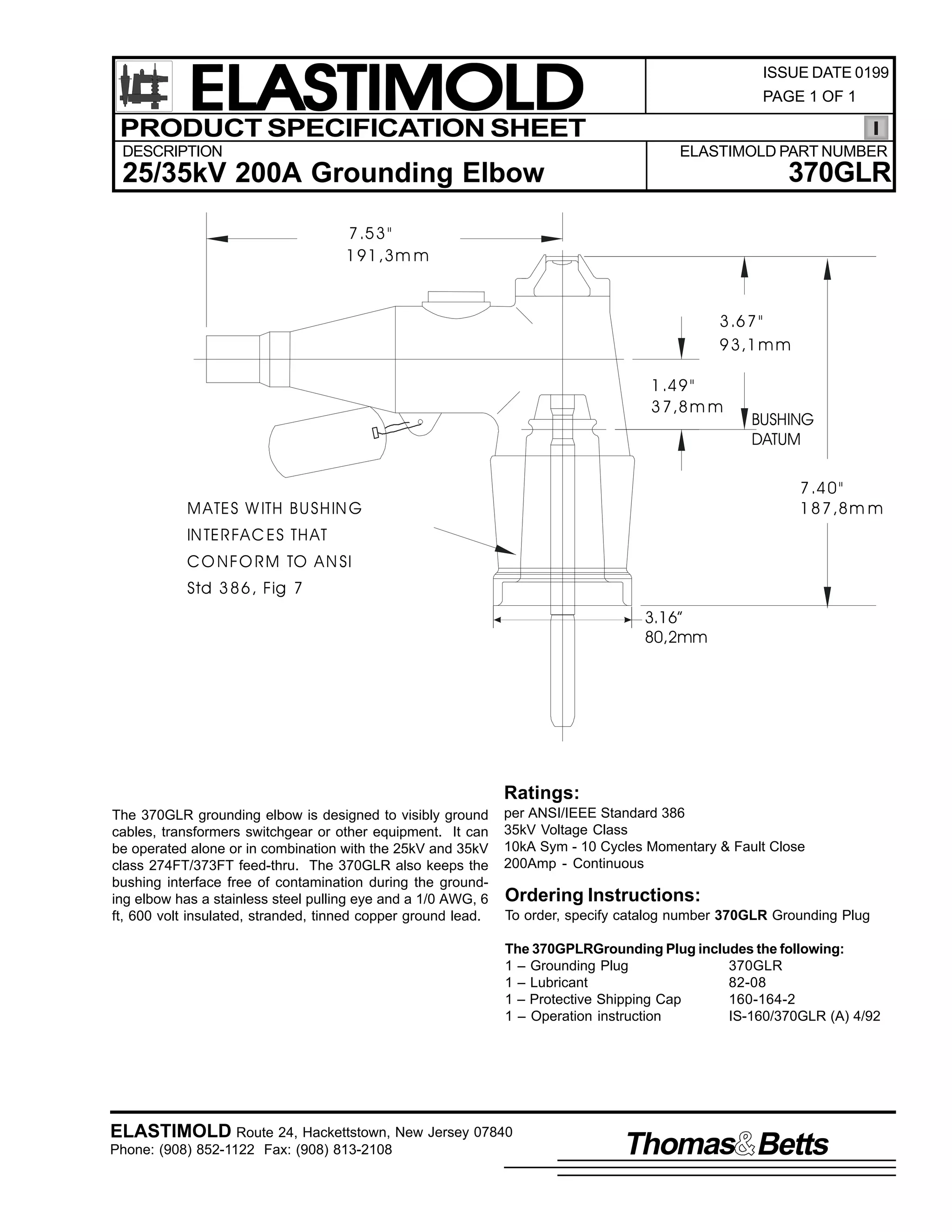
25kV 200A Repair Elbow
(w/o Test Point)
11.71"
297,0mm
ELASTIMOLD
R
3.87"
98,3mm
1.62"
41,1mm
MATES WITH BUSHING
INTERFACES THAT
CONFORM TO ANSI
Std 386, Fig 7
7.63"
194,0mm
2.88"
73,2mm
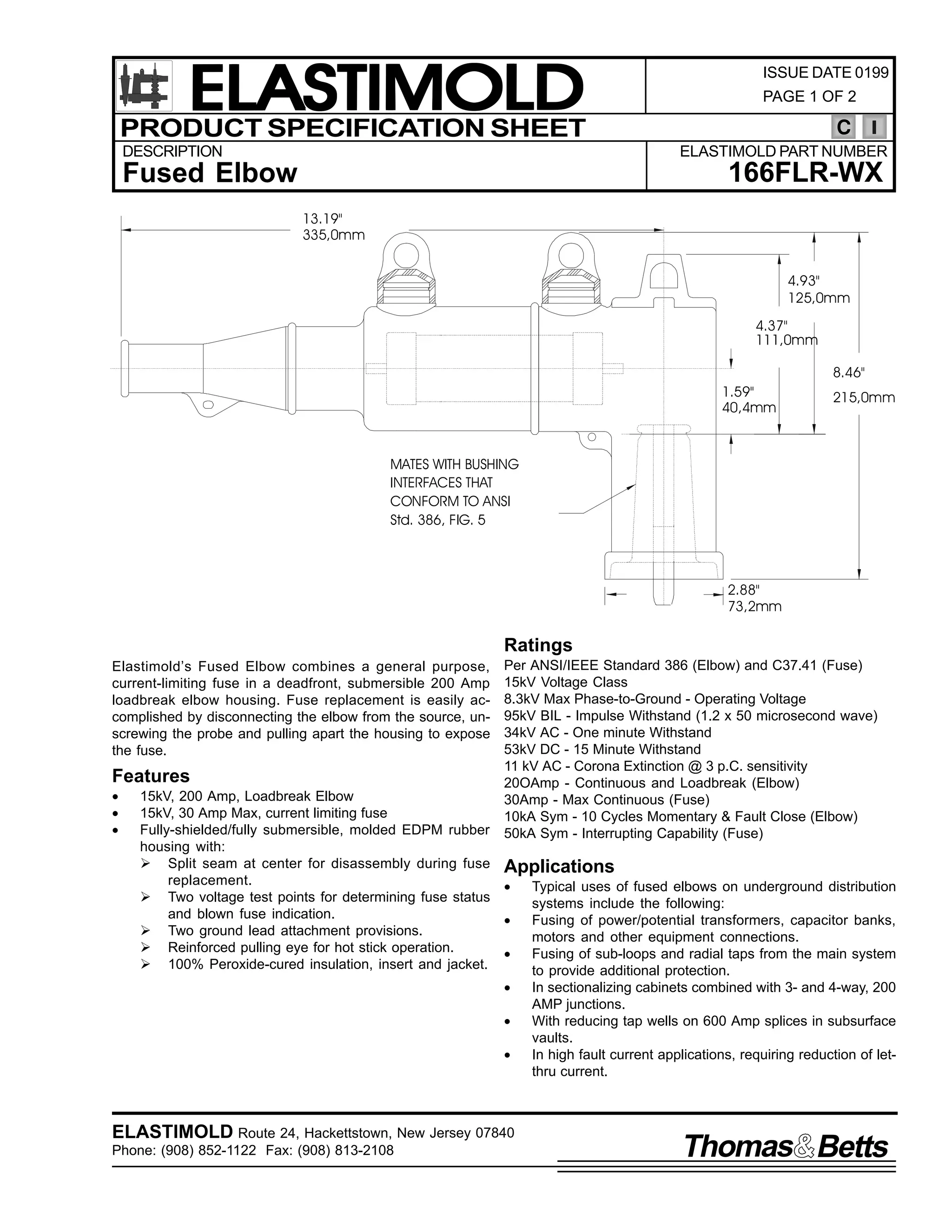
Ratings
The Elastimold 273ELR Repair Elbow is a fully rated 25kV
Class loadbreak elbow connector with a lengthened compression lug and housing. The Repair Elbow accommodates
cables that are too short to be connected to a standard elbow.
Features
•
•
•
•
Extended length housing and compression lug
[ + 3-1/4" (82,6mm)].
15kV, 200A Loadbreak Elbow Connector.
Fully shielded, fully submersible molded rubber housing.
Peroxide-cured insulation, insert and jacket.
NOTE: For housing extension greater than 3-1/4" (82,6mm),
refer to Elastimold Part number 273RLR.
per ANSI/IEEE Standard 386
25kV Voltage Class
15.2kV Max Phase-to-Ground - Operating Voltage
26.3kV Max Phase-to-Phase
125kV BIL - Impulse Withstand (1.2 x 50 microsecond wave)
40kV AC - One minute Withstand
78kV DC - 15 Minutes Withstand
19kV AC - Corona Extinction @ 3p.C.sensitivity
200 Amp - Continuous and Loadbreak
10kA Sym - 10 Cycles Momentary & Fault Close
Applications
The 273ELR is designed for connecting to and operating 25kV
Class, 125kV BIL distribution apparatus. Typical uses for the
special characteristics of the 273ELR Repair Elbow includes
the following:
•
Repair of a failed elbow connection where the cable must
be stripped back and a new compression lug applied.
•
To gain extra length when cables have been accidentally
trimmed too short or to connect new apparatus to existing
cables.
ELASTIMOLD Route 24, Hackettstown, New Jersey 07840
Phone: (908) 852-1122 Fax: (908) 813-2108
Thomas Betts](https://image.slidesharecdn.com/elastimold-140130102426-phpapp02/75/Elastimold-Connectors-Loadbreak-Deadbreak-Elbow-Bolted-Tee-Connectors-HV-MV-700-Series-74-2048.jpg)
![ELASTIMOLD
PRODUCT SPECIFICATION SHEET
ISSUE DATE 0199
PAGE 1 OF 2
C
DESCRIPTION
ELASTIMOLD PART NUMBER
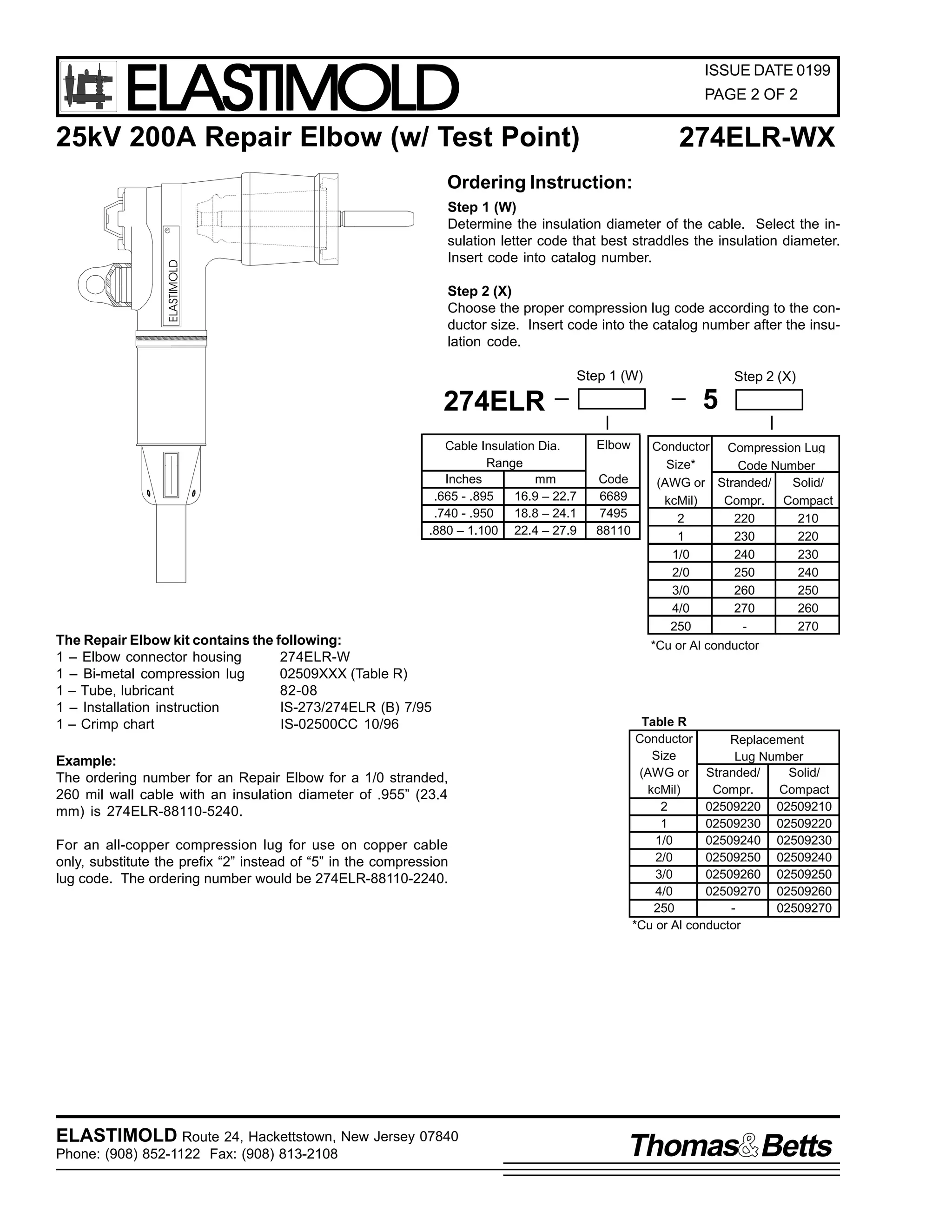
274ELR-WX
(w/ Test Point)
25kV 200A Repair Elbow
11.71"
297,0mm
4.70"
119,4mm
ELASTIMOLD
R
3.87"
98,3mm
1.62"
41,1mm
MATES WITH BUSHING
INTERFACES THAT
CONFORM TO ANSI
Std 386, Fig 7
8.40"
213,0mm
2.88"
73,2mm
Ratings
The Elastimold 274ELR Repair Elbow is a fully rated 25kV
Class loadbreak elbow connector with a lengthened compression lug and housing. The Repair Elbow accommodates
cables that are too short to be connected to a standard elbow.
Features
•
•
•
•
Extended length housing and compression lug
[ + 3-1/4" (82,6mm)].
15kV, 200A Loadbreak Elbow Connector.
Fully shielded, fully submersible molded rubber housing.
Peroxide-cured insulation, insert and jacket.
NOTE: For housing extension greater than 3-1/4" (82,6mm),
refer to Elastimold Part number 274RLR.
per ANSI/IEEE Standard 386
25kV Voltage Class
15.2kV Max Phase-to-Ground - Operating Voltage
26.3kV Max Phase-to-Phase
125kV BIL - Impulse Withstand (1.2 x 50 microsecond wave)
40kV AC - One minute Withstand
78kV DC - 15 Minutes Withstand
19kV AC - Corona Extinction @ 3p.C.sensitivity
200 Amp - Continuous and Loadbreak
10kA Sym - 10 Cycles Momentary & Fault Close
Applications
The 274ELR is designed for connecting to and operating 25kV
Class, 125kV BIL distribution apparatus. Typical uses for the
special characteristics of the 274ELR Repair Elbow includes
the following:
•
Repair of a failed elbow connection where the cable must
be stripped back and a new compression lug applied.
•
To gain extra length when cables have been accidentally
trimmed too short or to connect new apparatus to existing
cables.
ELASTIMOLD Route 24, Hackettstown, New Jersey 07840
Phone: (908) 852-1122 Fax: (908) 813-2108
Thomas Betts](https://image.slidesharecdn.com/elastimold-140130102426-phpapp02/75/Elastimold-Connectors-Loadbreak-Deadbreak-Elbow-Bolted-Tee-Connectors-HV-MV-700-Series-76-2048.jpg)
![ELASTIMOLD
PRODUCT SPECIFICATION SHEET
DESCRIPTION
ISSUE DATE 0199
PAGE 1 OF 2
C
ELASTIMOLD PART NUMBER
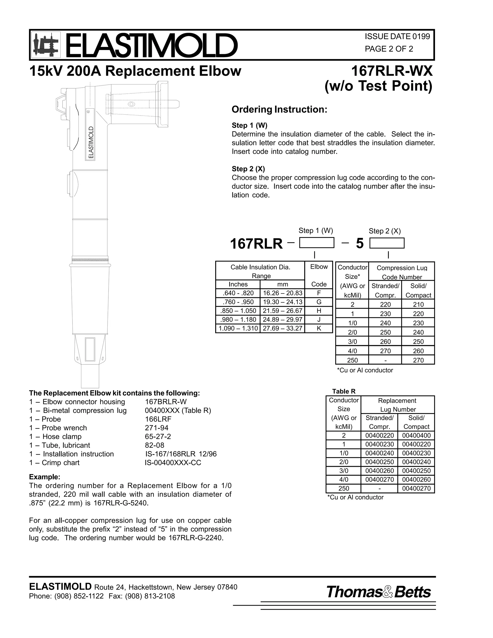
167RLR-WX
15kV 200A Replacement Elbow
(w/o Test Point)
18.00"
457,2mm
ELASTIMOLD
R
3.56"
90,4mm
1.31"
33,3mm
7.10"
180,0mm
MATES WITH BUSHING
INTERFACES THAT CONFORM
TO ANSI Std. 386, Fig. 5
2.93"
74,42mm
Ratings
The Elastimold 167RLR Replacement Elbow is a fully rated
15kV Class loadbreak elbow connector with a lengthened
compression lug and housing. The Replacement Elbow accommodates cables that are too short to be connected to a
standard elbow.
Features
•
•
•
•
Extended length housing and compression lug
[ + 10 ½ “ (266,7mm)].
15kV, 200A Loadbreak Elbow Connector.
Fully shielded, fully submersible molded rubber housing.
Peroxide-cured insulation, insert and jacket.
per ANSI/IEEE Standard 386
15kV Voltage Class
8.3 kV Max Phase-to-Ground - Operating Voltage
14.4kV Max Phase-to-Phase
95kV BIL - Impulse Withstand (1.2 x 50 microsecond wave)
34kV AC - One minute Withstand
53kV DC - 15 Minutes Withstand
11kV AC - Corona Extinciton @ 3p.C.sensitivity
200Amp - Continuous and Loadbreak
10kA Sym - 10 Cycles Momentary & Fault Clsoe
Applications
The 167RLR is designed for connecting to and operating 15kV
Class, 95kV BIL distribution apparatus. Typical uses for the
special characteristics of the 167RLR Replacement Elbow includes the following:
•
Repair of a failed elbow connection where the cable must
be stripped back and a new compression lug applied.
•
To gain extra length when cables have been accidentally
trimmed too short or to connect new apparatus to existing
cables.
•
Convert equipment connections from live front to dead front
without changing cable.
ELASTIMOLD Route 24, Hackettstown, New Jersey 07840
Phone: (908) 852-1122 Fax: (908) 813-2108
Thomas Betts](https://image.slidesharecdn.com/elastimold-140130102426-phpapp02/75/Elastimold-Connectors-Loadbreak-Deadbreak-Elbow-Bolted-Tee-Connectors-HV-MV-700-Series-83-2048.jpg)
![ELASTIMOLD
PRODUCT SPECIFICATION SHEET
ISSUE DATE 0199
PAGE 1 OF 2
C
DESCRIPTION
ELASTIMOLD PART NUMBER
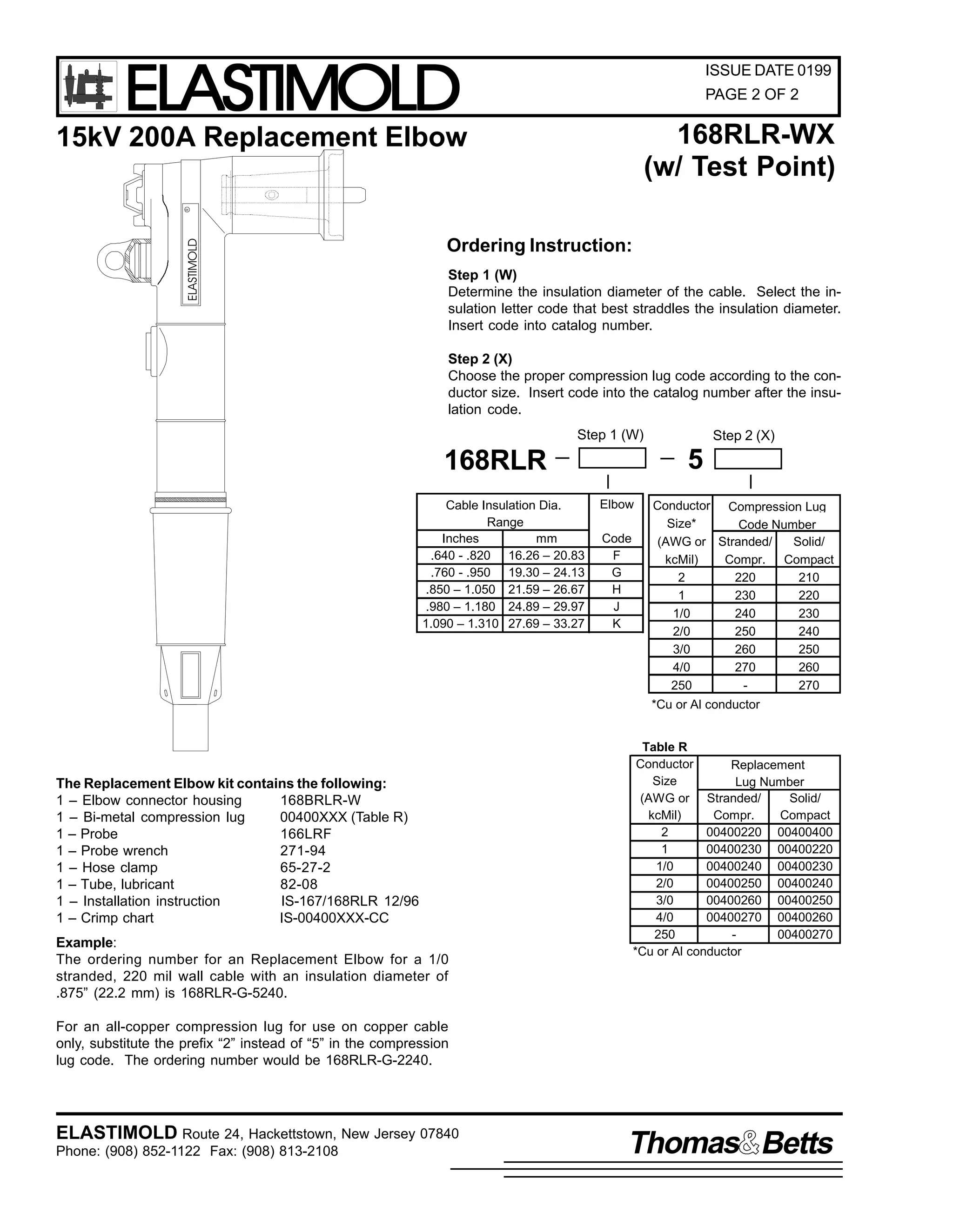
168RLR-WX
15kV 200A Replacement Elbow
(w/ Test Point)
18.00"
457,2mm
ELASTIMOLD
R
4.30"
3.56"
109,2mm
90,4mm
1.31"
33,3mm
MATES WITH BUSHING
INTERFACES THAT CONFORM
TO ANSI Std. 386, Fig. 5
7.95"
201,9mm
2.93"
74,42mm
Ratings
The Elastimold 168RLR Replacement Elbow is a fully rated
15kV Class loadbreak elbow connector with a lengthened
compression lug and housing. The Replacement Elbow accommodates cables that are too short to be connected to a
standard elbow.
Features
•
•
•
•
Extended length housing and compression lug
[ + 10 ½ “ (266,7mm)].
15kV, 200A Loadbreak Elbow Connector.
Fully shielded, fully submersible molded rubber housing.
Peroxide-cured insulation, insert and jacket.
per ANSI/IEEE Standard 386
15kV Voltage Class
8.3 kV Max Phase-to-Ground - Operating Voltage
14.4kV Max Phase-to-Phase
95kV BIL - Impulse Withstand (1.2 x 50 microsecond wave)
34kV AC - One minute Withstand
53kV DC - 15 Minutes Withstand
11kV AC - Corona Extinciton @ 3p.C.sensitivity
200Amp - Continuous and Loadbreak
10kA Sym - 10 Cycles Momentary & Fault Clsoe
Applications
The 168RLR is designed for connecting to and operating 15kV
Class, 95kV BIL distribution apparatus. Typical uses for the
special characteristics of the 168RLR Replacement Elbow includes the following:
•
Repair of a failed elbow connection where the cable must
be stripped back and a new compression lug applied.
•
To gain extra length when cables have been accidentally
trimmed too short or to connect new apparatus to existing
cables.
•
Convert equipment connections from live front to dead front
without changing cable.
ELASTIMOLD Route 24, Hackettstown, New Jersey 07840
Phone: (908) 852-1122 Fax: (908) 813-2108
Thomas Betts](https://image.slidesharecdn.com/elastimold-140130102426-phpapp02/75/Elastimold-Connectors-Loadbreak-Deadbreak-Elbow-Bolted-Tee-Connectors-HV-MV-700-Series-85-2048.jpg)

![ELASTIMOLD
PRODUCT SPECIFICATION SHEET
ISSUE DATE 0199
PAGE 1 OF 2
C
DESCRIPTION
ELASTIMOLD PART NUMBER
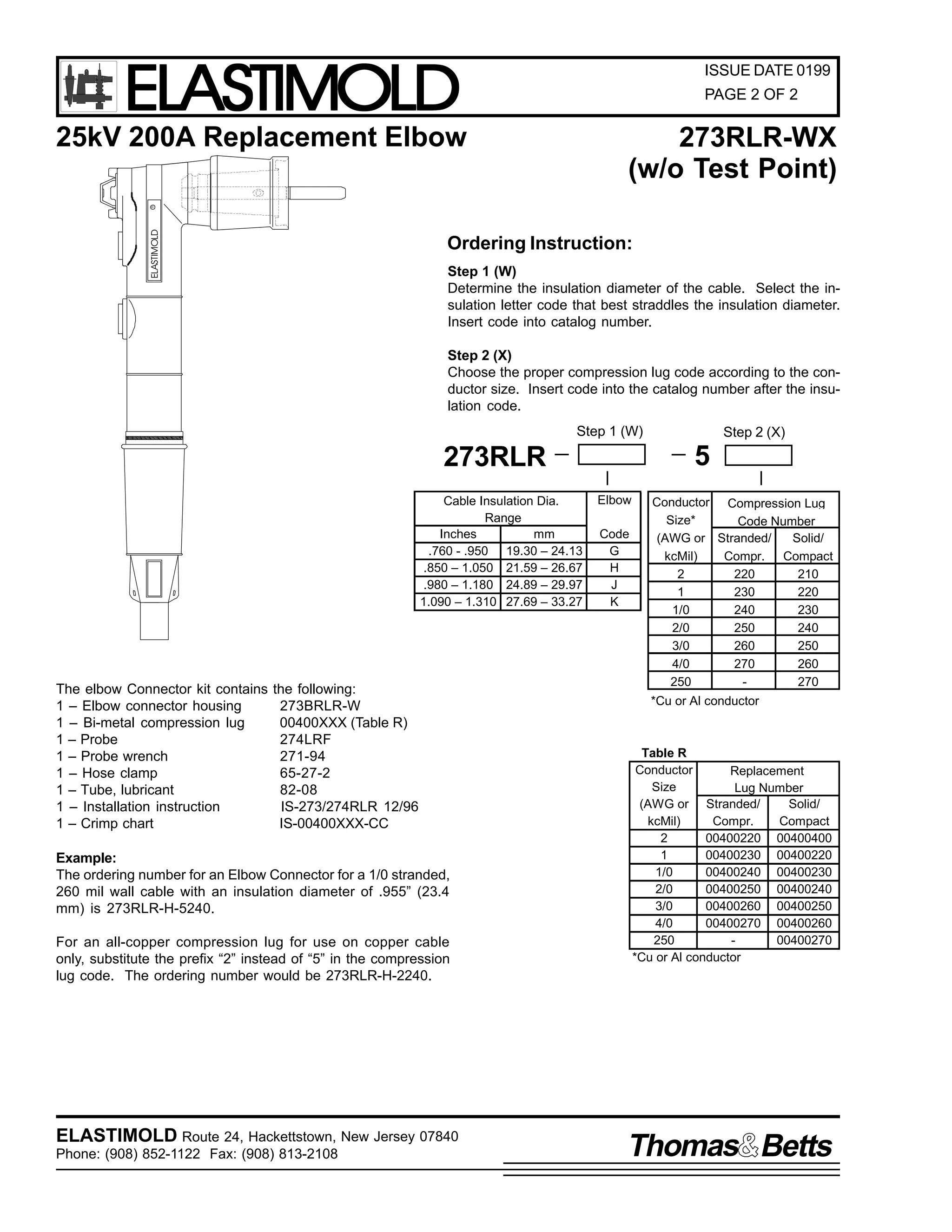
273RLR-WX
25kV 200A Replacement Elbow
(w/o Test Point)
18.00"
457,2mm
ELASTIMOLD
R
1.62"
41,1mm
3.87"
98,3mm
7.63"
194,0mm
MATES WITH BUSHING
INTERFACES THAT CONFORM
TO ANSI Std. 386, Fig. 7
2.93"
74,4mm
Ratings
The Elastimold 273RLR Replacement Elbow is a fully rated
25kV Class loadbreak elbow connector with a lengthened
compression lug and housing. The Replacement Elbow accommodates cables that are too short to be connected to a
standard elbow.
Features
•
•
•
•
Extended length housing and compression lug
[ + 10 ½ “ (266,7mm)].
25kV, 200A Loadbreak Elbow Connector.
Fully shielded, fully submersible molded rubber housing.
Peroxide-cured insulation, insert and jacket.
per ANSI/IEEE Standard 386
25kV Voltage Class
15.2kV Max Phase-to-Ground - Operating Voltage
26.3kV Max Phase-to-Phase
125kV BIL - Impulse Withstand (1.2 x 50 microsecond wave)
40kV AC - One minute Withstand
78kV DC - 15 Minutes Withstand
19kV AC - Corona Extinction @ 3p.C.sensitivity
200 Amp - Continuous and Loadbreak
10kA Sym - 10 Cycles Momentary & Fault Close
Applications
The 273RLR is designed for connecting to and operating 25kV
Class, 125kV BIL distribution apparatus. Typical uses for the
special characteristics of the 273RLR Replacement Elbow includes the following:
•
Repair of a failed elbow connection where the cable must
be stripped back and a new compression lug applied.
•
To gain extra length when cables have been accidentally
trimmed too short or to connect new apparatus to existing
cables.
•
Convert equipment connections from live front to dead front
without changing cable.
ELASTIMOLD Route 24, Hackettstown, New Jersey 07840
Phone: (908) 852-1122 Fax: (908) 813-2108
Thomas Betts](https://image.slidesharecdn.com/elastimold-140130102426-phpapp02/75/Elastimold-Connectors-Loadbreak-Deadbreak-Elbow-Bolted-Tee-Connectors-HV-MV-700-Series-91-2048.jpg)
![ELASTIMOLD
PRODUCT SPECIFICATION SHEET
ISSUE DATE 0199
PAGE 1 OF 2
C
DESCRIPTION
ELASTIMOLD PART NUMBER
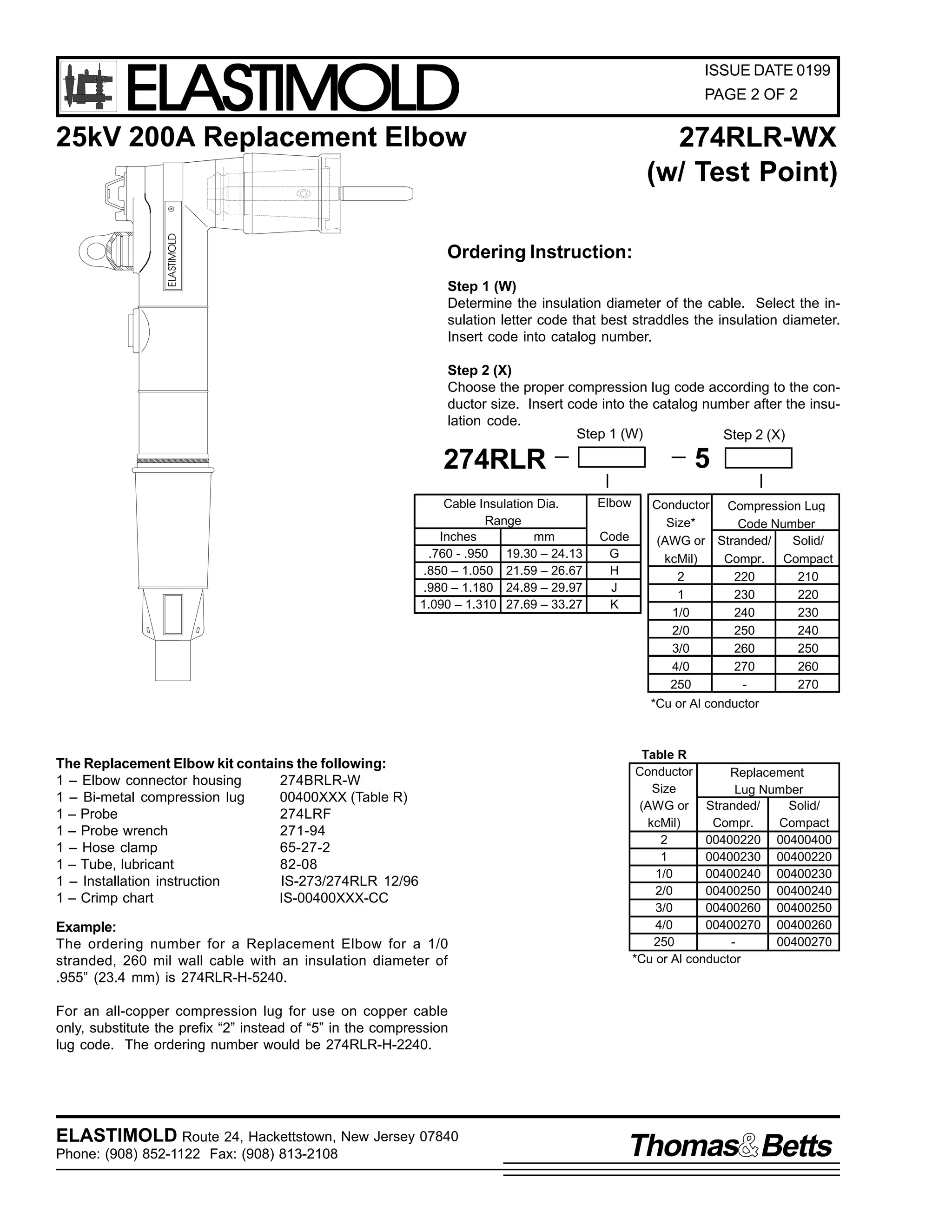
274RLR-WX
25kV 200A Replacement Elbow
(W/ Test Point)
18.00"
457,2mm
ELASTIMOLD
MATES WITH BUSHING
INTERFACES THAT CONFORM
R
4.70"
3.87"
119,4mm
98,3mm
1.62"
41,1mm
8.40"
213,4mm
2.93"
74,4mm
Ratings
The Elastimold 274RLR Replacement Elbow is a fully rated
25kV Class loadbreak elbow connector with a lengthened
compression lug and housing. The Replacement Elbow accommodates cables that are too short to be connected to a
standard elbow.
Features
•
•
•
•
Extended length housing and compression lug
[ + 10 ½ “ (266,7mm)].
25kV, 200A Loadbreak Elbow Connector.
Fully shielded, fully submersible molded rubber housing.
Peroxide-cured insulation, insert and jacket.
per ANSI/IEEE Standard 386
25kV Voltage Class
15.2kV Max Phase-to-Ground - Operating Voltage
26.3kV Max Phase-to-Phase
125kV BIL - Impulse Withstand (1.2 x 50 microsecond wave)
40kV AC - One minute Withstand
78kV DC - 15 Minutes Withstand
19kV AC - Corona Extinction @ 3p.C.sensitivity
200 Amp - Continuous and Loadbreak
10kA Sym - 10 Cycles Momentary & Fault Close
Applications
The 274RLR is designed for connecting to and operating 25kV
Class, 125kV BIL distribution apparatus. Typical uses for the
special characteristics of the 274RLR Replacement Elbow includes the following:
•
Repair of a failed elbow connection where the cable must
be stripped back and a new compression lug applied.
•
To gain extra length when cables have been accidentally
trimmed too short or to connect new apparatus to existing
cables.
•
Convert equipment connections from live front to dead front
without changing cable.
ELASTIMOLD Route 24, Hackettstown, New Jersey 07840
Phone: (908) 852-1122 Fax: (908) 813-2108
Thomas Betts](https://image.slidesharecdn.com/elastimold-140130102426-phpapp02/75/Elastimold-Connectors-Loadbreak-Deadbreak-Elbow-Bolted-Tee-Connectors-HV-MV-700-Series-93-2048.jpg)
![9
,60 05:625:75/5
'HFHPEHU 4<<9
3DJH 4 RI 7
,QVWDOODWLRQ ) 2SHUDWLQJ ,QVWUXFWLRQV
5:65/5 +ZLWKRXW 7HVW 3RLQW,
5:75/5 +ZLWK 7HVW 3RLQW,
/RDGEUHDN 5HSODFHPHQW (OERZ &RQQHFWRUV
&217(176=
5HSODFHPHQW (OERZ &RQQHFWRU +RXVLQJ/ &RPSUHVVLRQ /XJ/ 3UREH/ 3UREH :UHQFK/ /XEULFDQW/ +'R 1RW
6XEVWLWXWH,/ +RVH &ODPS/ ,QVWDOODWLRQ22SHUDWLQJ ,QVWUXFWLRQV1
7KH 5:65/5 +ZLWKRXW 7HVW 3RLQW, 5:75/5 +ZLWK 7HVW 3RLQW, LV GHVLJQHG WR FRQYHUW D OLYHIURQW WHUPLQDWLRQ WR GHDGIURQW IRU 8' FDEOH
KDYLQJ FRQFHQWULF QHXWUDO DQG H[WUXGHG LQVXODWLRQ VKLHOGLQJ1 7KH HOERZ SURYLGHV DQ RSHUDWLQJ LQWHUIDFH IRU FRQQHFWLQJ WR DQ
(ODVWLPROG 58N9 FODVV +4815N9 SKDVH0 0WR0 0JURXQG DQG 5916N9 SKDVH0 0WR0 0SKDVH, 533 DPSHUH ORDGEUHDN EXVKLQJ RU DFFHVVRU
GHYLFH ZLWK IDXOW FORVH UDWLQJV RI 43/333 DPSHUHV 506/ VPPHWULFDO1 :KHQ RWKHU WSHV RI 8' FDEOH DUH WR EH WHUPLQDWHG DQ
DSSURSULDWH (ODVWLPROG FDEOH VKLHOG RU JURXQGLQJ GHYLFH PXVW EH XVHG1
'$1*(5
$OO DSSDUDWXV PXVW EH GH0 0HQHUJL]HG GXULQJ LQVWDOODWLRQ
RU UHPRYDO RI SDUW+V,1
'R QRW WRXFK RU PRYH HQHUJL]HG SURGXFWV E KDQG1
([FHVV GLVWRUWLRQ RI WKH DVVHPEOHG SURGXFW PD UHVXOW LQ
LWV IDLOXUH1
,QVSHFW SDUWV IRU GDPDJH/ UDWLQJ DQG FRPSDWLELOLW ZLWK
PDWLQJ SDUWV1
7KLV SURGXFW VKRXOG EH LQVWDOOHG RQO E FRPSHWHQW
SHUVRQQHO WUDLQHG LQ JRRG VDIHW SUDFWLFHV LQYROYLQJ KLJK
YROWDJH HOHFWULFDO HTXLSPHQW1 7KHVH LQVWUXFWLRQV DUH QRW
LQWHQGHG DV D VXEVWLWXWH IRU DGHTXDWH WUDLQLQJ RU
H[SHULHQFH LQ VXFK VDIHW SUDFWLFHV1
7KHVH LQVWUXFWLRQV GR QRW DWWHPSW WR SURYLGH IRU HYHU
SRVVLEOH FRQWLQJHQF1
)DLOXUH WR IROORZ WKHVH LQVWUXFWLRQV ZLOO UHVXOW LQ GDPDJH
WR WKH SURGXFW DQG VHULRXV RU IDWDO LQMXU1
)25 025( ,1)250$7,21 21 3$576/ ,167$//$7,21 5$7,1*6 $1' &203$7,%,/,7</ &$// 7+( 1($5(67 (/$67,02/' 2)),&(1
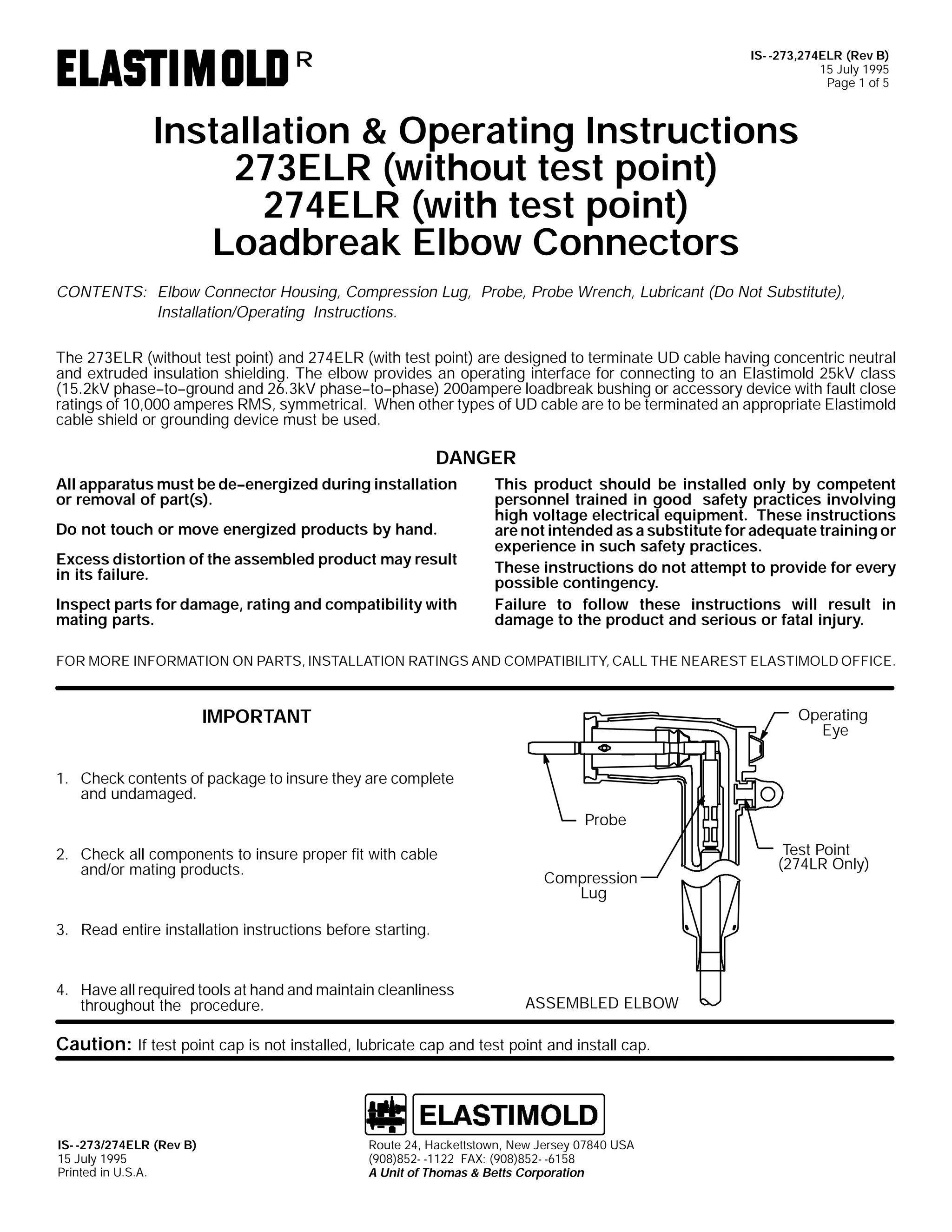
,03257$17
41 &KHFN FRQWHQWV RI SDFNDJH WR LQVXUH WKH DUH FRPSOHWH
DQG XQGDPDJHG1
2SHUDWLQJ
(H
3UREH
51 &KHFN DOO FRPSRQHQWV WR LQVXUH SURSHU ILW ZLWK FDEOH
DQG2RU PDWLQJ SURGXFWV1
7HVW 3RLQW
+5:75/5 21/<,
61 5HDG HQWLUH LQVWDOODWLRQ LQVWUXFWLRQV EHIRUH VWDUWLQJ1
71 +DYH DOO UHTXLUHG WRROV DW KDQG DQG PDLQWDLQ FOHDQOLQHVV
WKURXJKRXW WKH SURFHGXUH1
&RPSUHVVLRQ
/XJ
+RVH &ODPS
*URXQG
:LUH
$66(0%/(' (/%2:
&$87,21= ,I WHVW SRLQW FDS LV QRW LQVWDOOHG/ OXEULFDWH FDS DQG WHVW SRLQW DQG LQVWDOO FDS1
,60 05:625:75/5
'HFHPEHU 4<<9
3ULQWHG LQ 8161$1
(VQD 3DUN 'ULYH/ +DFNHWWVWRZQ/ 1HZ -HUVH 3:;73 86$
+<3;,;850 04455 )$;= +<3;,;460 0547:
$ 8QLW RI 7KRPDV ) %HWWV &RUSRUDWLRQ](https://image.slidesharecdn.com/elastimold-140130102426-phpapp02/75/Elastimold-Connectors-Loadbreak-Deadbreak-Elbow-Bolted-Tee-Connectors-HV-MV-700-Series-95-2048.jpg)
![,60 05:625:75/5
'HFHPEHU 4<<9
3DJH 7 RI 7
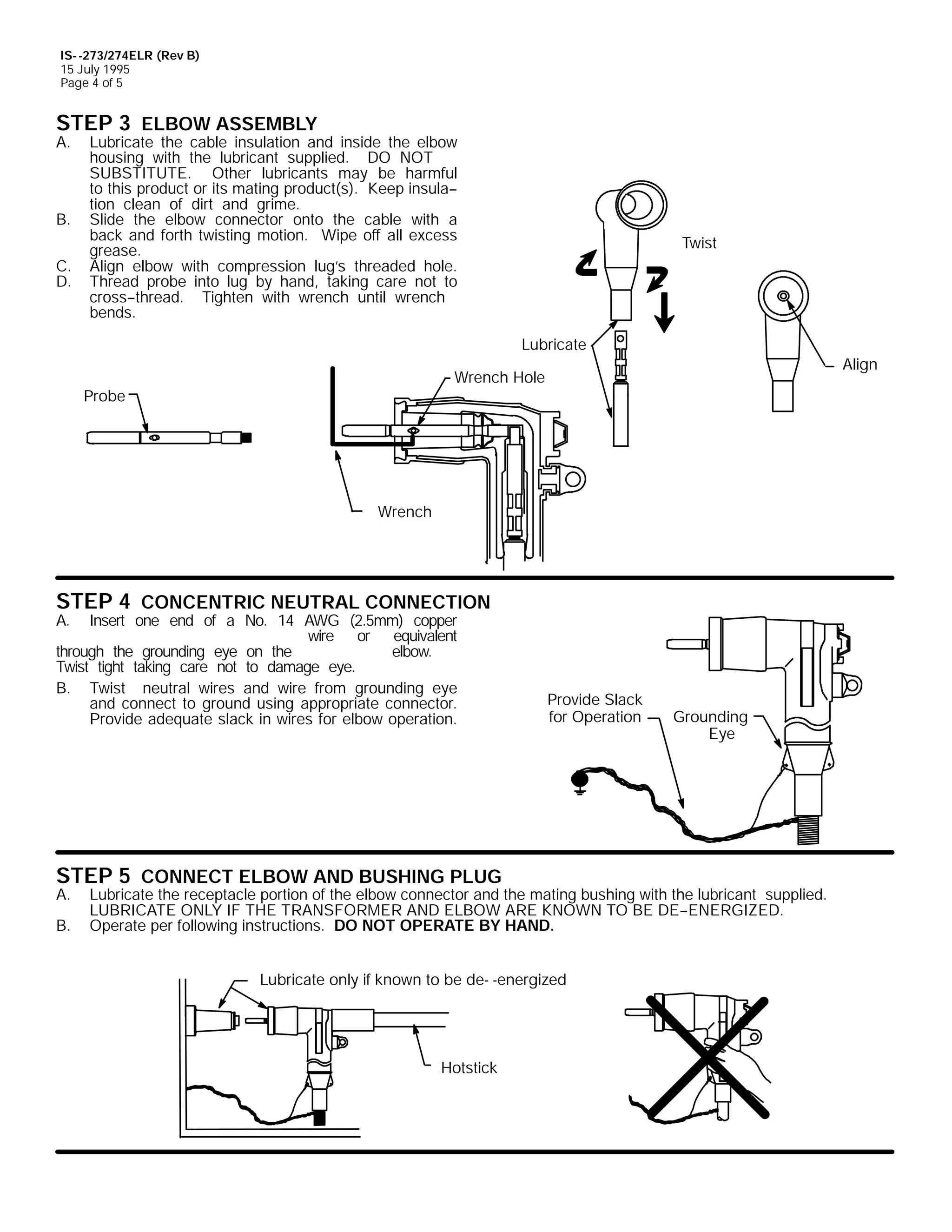
67(3 9 &211(&7 (/%2: $1' %86+,1* 3/8*
$1 /XEULFDWH WKH UHFHSWDFOH SRUWLRQ RI WKH HOERZ FRQQHFWRU DQG WKH PDWLQJ EXVKLQJ ZLWK WKH OXEULFDQW VXSSOLHG1 /8%5,&$7(
21/< ,) 7+( 75$16)250(5 $1' (/%2: $5( .12:1 72 %( '(0 0(1(5*,=('1
%1 2SHUDWH SHU IROORZLQJ LQVWUXFWLRQV1 '2 127 23(5$7( %< +$1'1
/XEULFDWH RQO LI NQRZQ WR EH GH0 0HQHUJL]HG
+RWVWLFN
23(5$7,1* ,16758&7,216
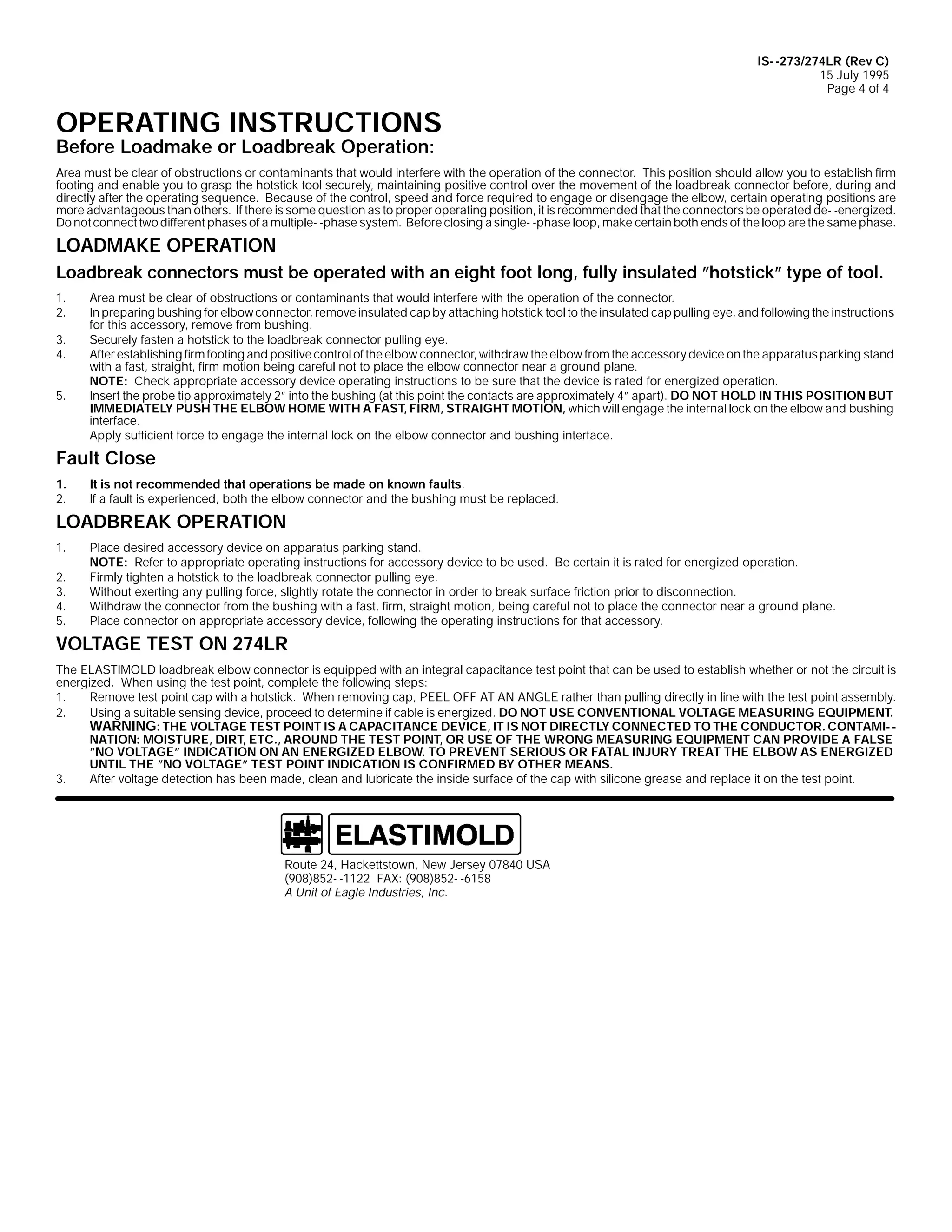
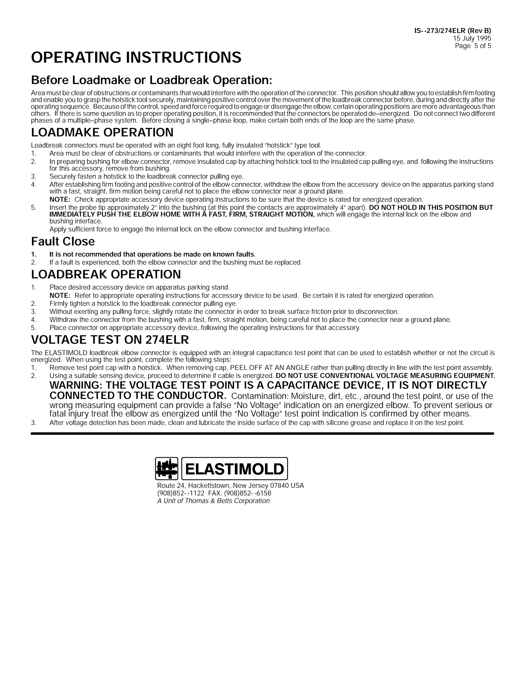
%HIRUH /RDGPDNH RU /RDGEUHDN 2SHUDWLRQ=
/RDGEUHDN FRQQHFWRUV PXVW EH RSHUDWHG ZLWK DQ HLJKW IRRW ORQJ/ IXOO LQVXODWHG lKRWVWLFNl WSH RI WRRO1
$UHD PXVW EH FOHDU RI REVWUXFWLRQV RU FRQWDPLQDQWV WKDW ZRXOG LQWHUIHUH ZLWK WKH RSHUDWLRQ RI WKH FRQQHFWRU1 7KLV SRVLWLRQ VKRXOG DOORZ RX WR HVWDEOLVK ILUP IRRWLQJ
DQG HQDEOH RX WR JUDVS WKH KRWVWLFN WRRO VHFXUHO/ PDLQWDLQLQJ SRVLWLYH FRQWURO RYHU WKH PRYHPHQW RI WKH ORDGEUHDN FRQQHFWRU EHIRUH/ GXULQJ DQG GLUHFWO DIWHU WKH
RSHUDWLQJ VHTXHQFH1 %HFDXVH RI WKH FRQWURO/ VSHHG DQG IRUFH UHTXLUHG WR HQJDJH RU GLVHQJDJH WKH HOERZ/ FHUWDLQ RSHUDWLQJ SRVLWLRQV DUH PRUH DGYDQWDJHRXV WKDQ
RWKHUV1 ,I WKHUH LV VRPH TXHVWLRQ DV WR SURSHU RSHUDWLQJ SRVLWLRQ/ LW LV UHFRPPHQGHG WKDW WKH FRQQHFWRUV EH RSHUDWHG GH0 0HQHUJL]HG1 'R QRW FRQQHFW WZR GLIIHUHQW
SKDVHV RI D PXOWLSOH0 0SKDVH VVWHP1 %HIRUH FORVLQJ D VLQJOH0 0SKDVH ORRS/ PDNH FHUWDLQ ERWK HQGV RI WKH ORRS DUH WKH VDPH SKDVH1
/2$'0$.( 23(5$7,21
&$87,21= &KHFN DSSURSULDWH DFFHVVRU GHYLFH RSHUDWLQJ LQVWUXFWLRQV WR EH VXUH WKDW WKH GHYLFH LV UDWHG IRU HQHUJL]HG RSHUDWLRQ1
41
51
61
71
81
$UHD PXVW EH FOHDU RI REVWUXFWLRQV RU FRQWDPLQDQWV WKDW ZRXOG LQWHUIHUH ZLWK WKH RSHUDWLRQ RI WKH FRQQHFWRU1
,Q SUHSDULQJ EXVKLQJ IRU HOERZ FRQQHFWRU/ UHPRYH LQVXODWHG FDS E DWWDFKLQJ KRWVWLFN WRRO WR WKH LQVXODWHG FDS SXOOLQJ HH/ DQG IROORZLQJ WKH LQVWUXFWLRQV IRU
WKLV DFFHVVRU/ UHPRYH IURP EXVKLQJ1
6HFXUHO IDVWHQ D KRWVWLFN WR WKH ORDGEUHDN FRQQHFWRU SXOOLQJ HH1
$IWHU HVWDEOLVKLQJ ILUP IRRWLQJ DQG SRVLWLYH FRQWURO RI WKH HOERZ FRQQHFWRU/ ZLWKGUDZ WKH HOERZ IURP WKH DFFHVVRU GHYLFH RQ WKH DSSDUDWXV SDUNLQJ VWDQG
ZLWK D IDVW/ VWUDLJKW/ ILUP PRWLRQ EHLQJ FDUHIXO QRW WR SODFH WKH HOERZ FRQQHFWRU QHDU D JURXQG SODQH1
3ODFH WKH HOERZ FRQQHFWRU UHFHSWDFOH DUHD RYHU WKH EXVKLQJ SOXJ/ LQVHUWLQJ WKH HOERZ PDOH FRQWDFW +DUF IROORZHU SRUWLRQ, LQWR WKH EXVKLQJ XQWLO WKH ILUVW VOLJKW
UHVLVWDQFH LV IHOW1 5HVLVWDQFH LV IHOW ZKHQ WKH DUF IROORZHU SRUWLRQ RI WKH PDOH FRQWDFW ILUVW PHHWV WKH IHPDOH FRQWDFW RI WKH EXVKLQJ +DW WKLV SRLQW WKH FRQWDFWV DUH
DSSUR[LPDWHO 5l DSDUW,1
&$87,21= 'R QRW KROG LQ WKLV SRVLWLRQ EXW LPPHGLDWHO SXVK WKH HOERZ KRPH ZLWK D IDVW/ ILUP/ VWUDLJKW PRWLRQ/ ZKLFK ZLOO HQJDJH WKH LQWHUQDO ORFN RQ WKH
HOERZ DQG EXVKLQJ LQWHUIDFH1
$SSO VXIILFLHQW IRUFH WR HQJDJH WKH LQWHUQDO ORFN RQ WKH HOERZ FRQQHFWRU DQG EXVKLQJ LQWHUIDFH1
)DXOW &ORVH
41
51
,W LV QRW UHFRPPHQGHG WKDW RSHUDWLRQV EH PDGH RQ NQRZQ IDXOWV1
,I D IDXOW LV H[SHULHQFHG/ ERWK WKH HOERZ FRQQHFWRU DQG WKH EXVKLQJ PXVW EH UHSODFHG1
/2$'%5($. 23(5$7,21
41
51
61
71
81
3ODFH GHVLUHG DFFHVVRU GHYLFH RQ DSSDUDWXV SDUNLQJ VWDQG1
&$87,21= 5HIHU WR DSSURSULDWH RSHUDWLQJ LQVWUXFWLRQV IRU DFFHVVRU GHYLFH WR EH XVHG1 %H FHUWDLQ LW LV UDWHG IRU HQHUJL]HG RSHUDWLRQ1
)LUPO WLJKWHQ D KRWVWLFN WR WKH ORDGEUHDN FRQQHFWRU SXOOLQJ HH1
:LWKRXW H[HUWLQJ DQ SXOOLQJ IRUFH/ VOLJKWO URWDWH WKH FRQQHFWRU LQ RUGHU WR EUHDN VXUIDFH IULFWLRQ SULRU WR GLVFRQQHFWLRQ1
:LWKGUDZ WKH FRQQHFWRU IURP WKH EXVKLQJ ZLWK D IDVW/ ILUP/ VWUDLJKW PRWLRQ/ EHLQJ FDUHIXO QRW WR SODFH WKH FRQQHFWRU QHDU D JURXQG SODQH1
3ODFH FRQQHFWRU RQ DSSURSULDWH DFFHVVRU GHYLFH/ IROORZLQJ WKH RSHUDWLQJ LQVWUXFWLRQV IRU WKDW DFFHVVRU1
92/7$*( 7(67 21 5:75/5
7KH (/$67,02/' ORDGEUHDN HOERZ FRQQHFWRU LV HTXLSSHG ZLWK DQ LQWHJUDO FDSDFLWDQFH WHVW SRLQW WKDW FDQ EH XVHG WR HVWDEOLVK ZKHWKHU RU QRW WKH FLUFXLW LV
HQHUJL]HG1 :KHQ XVLQJ WKH WHVW SRLQW/ FRPSOHWH WKH IROORZLQJ VWHSV=
41
5HPRYH WHVW SRLQW FDS ZLWK D KRWVWLFN1 :KHQ UHPRYLQJ FDS/ 3((/ 2)) $7 $1 $1*/( UDWKHU WKDQ SXOOLQJ GLUHFWO LQ OLQH ZLWK WKH WHVW SRLQW DVVHPEO1
51
8VLQJ D VXLWDEOH VHQVLQJ GHYLFH/ SURFHHG WR GHWHUPLQH LI FDEOH LV HQHUJL]HG1 '2 127 86( &219(17,21$/ 92/7$*( 0($685,1* (48,30(171
:$51,1*= 7+( 92/7$*( 7(67 32,17 ,6 $ &$3$&,7$1&( '(9,&(/ ,7 ,6 127 ',5(&7/< &211(&7(' 72 7+(
&21'8&7251 &RQWDPLQDWLRQ= PRLVWXUH/ GLUW/ HWF1 DURXQG WKH WHVW SRLQW/ RU XVH RI WKH ZURQJ PHDVXULQJ HTXLSPHQW FD SURYLGH D IDOVH k12 92/7$*(l
61
LQGLFDWLRQ RQ DQ HQHUJL]HG HOERZ1 7R SUHYHQW VHULRXV RU IDWDO LQMXU WUHDW WKH HOERZ DV HQHUJL]HG XQWLO WKH k1R 9ROWDJHl WHVW SRLQW LQGLFDWLRQ LV FRQILUPHG E
RWKHU PHDQV1
$IWHU YROWDJH GHWHFWLRQ KDV EHHQ PDGH/ FOHDQ DQG OXEULFDWH WKH LQVLGH VXUIDFH RI WKH FDS ZLWK VLOLFRQH JUHDVH DQG UHSODFH LW RQ WKH WHVW SRLQW1](https://image.slidesharecdn.com/elastimold-140130102426-phpapp02/75/Elastimold-Connectors-Loadbreak-Deadbreak-Elbow-Bolted-Tee-Connectors-HV-MV-700-Series-98-2048.jpg)

![9
,QVWDOODWLRQ ,QVWUXFWLRQV
4934$7
/RDGEUHDN %XVKLQJ ,QVHUW
,60 04934$7 +5HY $,
4 -XO 4<<3
3DJH 4
&217(176= 40 0/RDGEUHDN %XVKLQJ ,QVHUW/ /XEULFDQW +'2 127 68%67,787(,/ 40 0,QVWDOODWLRQ ,QVWUXFWLRQ
7KH 4934$7 LV GHVLJQHG WR SURYLGH WKH DSSDUDWXV LQWHUIDFH IRU (ODVWLPROG 48N9 FODVV +;16N9 SKDVH0 0WR0 0JURXQG DQG 4717N9
SKDVH0 0WR0 0SKDVH, ORDGEUHDN FRQQHFWLRQV1
'$1*(5
$OO DSSDUDWXV PXVW EH GH0 0HQHUJL]HG GXULQJ LQVWDOODWLRQ
RU UHPRYDO RI SDUW+V,1
'R QRW WRXFK RU PRYH HQHUJL]HG FDEOHV DQG2RU SURGXFWV
E KDQG1
([FHVV GLVWRUWLRQ RI WKH DVVHPEOHG SURGXFW PD UHVXOW
LQ LWV IDLOXUH1
,QVSHFW SDUWV IRU GDPDJH/ UDWLQJ DQG FRPSDWLELOLW ZLWK
PDWLQJ SDUWV1
7KLV SURGXFW VKRXOG EH LQVWDOOHG RQO E FRPSHWHQW
SHUVRQQHO WUDLQHG LQ JRRG VDIHW SUDFWLFHV LQYROYLQJ
KLJK YROWDJH HOHFWULFDO HTXLSPHQW1 7KHVH LQVWUXFWLRQV
DUH QRW LQWHQGHG DV D VXEVWLWXWH IRU DGHTXDWH WUDLQLQJ RU
H[SHULHQFH LQ VXFK VDIHW SUDFWLFHV1
7KHVH LQVWUXFWLRQV GR QRW DWWHPSW WR SURYLGH IRU HYHU
SRVVLEOH FRQWLQJHQF1
)DLOXUH WR IROORZ WKHVH LQVWUXFWLRQV FRXOG UHVXOW LQ
GDPDJH WR WKH SURGXFW DQG VHULRXV RU IDWDO LQMXU1
7KLV SURGXFW LV VXSSOLHG ZLWK D SURWHFWLYH VKLSSLQJ FDS1
5HPRYH WKLV VKLSSLQJ FDS DQG UHSODFH ZLWK WKH
DSSURSULDWH +9 LQVXODWHG2VKLHOGHG GHDGHQG FDS RU
FRQQHFWRU EHIRUH VXEPHUJLQJ RU HQHUJL]LQJ WKH FLUFXLW1
)25 025( ,1)250$7,21 21 3$576/ ,167$//$7,21 5$7,1*6 $1' &203$7,%,/,7</ &$// 7+( 1($5(67 (/$67,02/' 2)),&(1
,03257$17
41 &KHFN FRQWHQWV RI SDFNDJH WR LQVXUH WKH DUH FRPSOHWH
DQG XQGDPDJHG1
51 &KHFN DOO FRPSRQHQWV WR LQVXUH SURSHU ILW ZLWK FDEOH
DQG2RU PDWLQJ SURGXFWV1
61 5HDG HQWLUH LQVWDOODWLRQ LQVWUXFWLRQV EHIRUH VWDUWLQJ1
71 +DYH DOO UHTXLUHG WRROV DW KDQG DQG PDLQWDLQ FOHDQOLQHVV
WKURXJKRXW WKH SURFHGXUH1
67(3 4
67(3 5
,QVSHFW WKH DSSDUDWXV EXVKLQJ ZHOO WR HQVXUH LW LV GU DQG
IUHH IURP DOO FRQWDPLQDQWV1
5HPRYH WKH SURWHFWLYH
VKLSSLQJ FDS IURP WKH EXVKLQJ LQVHUW1 /XEULFDWH WKH
EXVKLQJ ZHOO LQWHUIDFH DUHD RI WKH EXVKLQJ LQVHUW ZLWK WKH
VXSSOLHG OXEULFDQW RU (/$67,02/' DSSURYHG OXEULFDQWV1
'2 127 68%67,787(1 2WKHU OXEULFDQWV PD EH KDUPIXO WR
WKLV SURGXFW DQG LWV PDWLQJ SURGXFWV1
/XEULFDWH
3ODFH WKH OXEULFDWHG SRUWLRQ RI WKH EXVKLQJ LQVHUW LQ WKH
DSSDUDWXV EXVKLQJ ZHOO1 +DQG WLJKWHQ WKH EXVKLQJ LQVHUW LQ
D FORFNZLVH GLUHFWLRQ XQWLO LW ERWWRPV1
5(029(
$SSDUDWXV
/XEULFDWH
%XVKLQJ :HOO ODPSHG
&
+RU :HOGHG 7SH,
6KLSSLQJ &DS
7(3 5 0 0 $/7(51$7(
ODFH WKH OXEULFDWHG SRUWLRQ RI WKH EXVKLQJ LQVHUW LQ WKH
SSDUDWXV EXVKLQJ ZHOO1 ,QVHUW 533$7 DVVHPEO WRRO LQ
RUH RI EXVKLQJ LQVHUW XQWLO IXOO VHDWHG1 ,QVHUW VXLWDEOH
RG WKURXJK WKH HH RI WKH WRRO DQG WXUQ LQ D FORFNZLVH
LUHFWLRQ1 &RQWLQXH WR URWDWH WKH HH RI WKH 533$7 XQWLO LW
HJLQV WR UDWFKHW VLJQLILQJ WKH SURSHU DVVHPEO WRUTXH
DV EHHQ UHDFKHG1 5HPRYH 533$7 IURP EXVKLQJ LQVHUW1
,60 04934$7 +5HY $,
4 -XO 4<<3
3ULQWHG LQ 8161$1
(VQD 3DUN 'ULYH/ +DFNHWWVWRZQ/ 1HZ -HUVH 3:;73 86$
+<3;,;85004455 )$;= +<3;,;4600547:
$ 8QLW RI 7KRPDV ) %HWWV &RUSRUDWLRQ
533$7
+$VVHPEO 7RRO,
&OHDQ 7RRO
%HIRUH ,QVHUWLRQ](https://image.slidesharecdn.com/elastimold-140130102426-phpapp02/75/Elastimold-Connectors-Loadbreak-Deadbreak-Elbow-Bolted-Tee-Connectors-HV-MV-700-Series-107-2048.jpg)
![,60 04934$7 +5HY $,
4 -XO 4<<3
3DJH 5
67(3 6
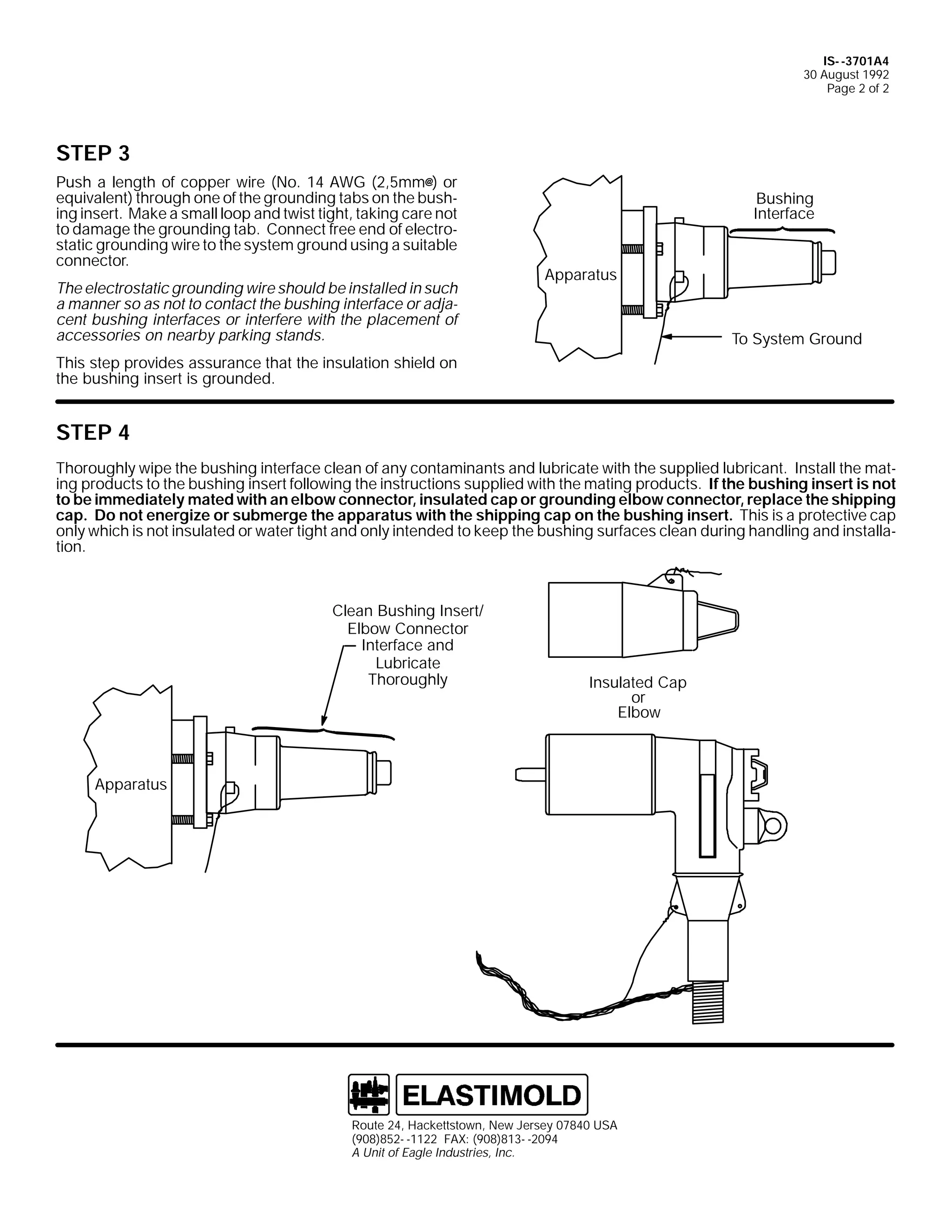
3XVK D OHQJWK RI FRSSHU ZLUH +1R1 47 $:* +5/8PP), RU
HTXLYDOHQW, WKURXJK RQH RI WKH JURXQGLQJ WDEV RQ WKH
EXVKLQJ LQVHUW1 0DNH D VPDOO ORRS DQG WZLVW WLJKW/ WDNLQJ
FDUH QRW WR GDPDJH WKH JURXQGLQJ WDE1 &RQQHFW IUHH HQG RI
HOHFWURVWDWLF JURXQGLQJ ZLUH WR WKH VVWHP JURXQG XVLQJ D
VXLWDEOH FRQQHFWRU1
7KH HOHFWURVWDWLF JURXQGLQJ ZLUH VKRXOG EH LQVWDOOHG LQ VXFK
D PDQQHU VR DV QRW WR FRQWDFW WKH EXVKLQJ LQWHUIDFH RU
DGMDFHQW EXVKLQJ LQWHUIDFHV RU LQWHUIHUH ZLWK WKH SODFHPHQW
RI DFFHVVRULHV RQ QHDUE SDUNLQJ VWDQGV1
%XVKLQJ
,QWHUIDFH
$SSDUDWXV
7R 6VWHP *URXQG
7KLV VWHS SURYLGHV DVVXUDQFH WKDW WKH LQVXODWLRQ VKLHOG RQ
WKH EXVKLQJ LQVHUW LV JURXQGHG1
67(3 7
7KRURXJKO ZLSH WKH EXVKLQJ LQWHUIDFH FOHDQ RI DQ
FRQWDPLQDQWV DQG OXEULFDWH ZLWK WKH VXSSOLHG OXEULFDQW1
,QVWDOO WKH PDWLQJ SURGXFWV WR WKH EXVKLQJ LQVHUW IROORZLQJ
WKH LQVWUXFWLRQV VXSSOLHG ZLWK WKH PDWLQJ SURGXFWV1 ,I WKH
EXVKLQJ LQVHUW LV QRW WR EH LPPHGLDWHO PDWHG ZLWK DQ
HOERZ FRQQHFWRU/ LQVXODWHG FDS RU JURXQGLQJ HOERZ
&OHDQ %XVKLQJ ,QVHUW2
(OERZ &RQQHFWRU
,QWHUIDFH DQG
/XEULFDWH
7KRURXJKO
FRQQHFWRU/ UHSODFH WKH VKLSSLQJ FDS1 'R QRW HQHUJL]H RU
VXEPHUJH WKH DSSDUDWXV ZLWK WKH VKLSSLQJ FDS RQ WKH
EXVKLQJ LQVHUW1 7KLV LV D SURWHFWLYH FDS RQO ZKLFK LV QRW
LQVXODWHG RU ZDWHU WLJKW DQG RQO LQWHQGHG WR NHHS WKH
EXVKLQJ VXUIDFHV FOHDQ GXULQJ KDQGOLQJ DQG LQVWDOODWLRQ1
,QVXODWHG &DS
RU
(OERZ
$SSDUDWXV
(VQD 3DUN 'ULYH/ +DFNHWWVWRZQ/ 1HZ -HUVH 3:;73 86$
+<3;,;85004455 )$;= +<3;,;4600547:
$ 8QLW RI 7KRPDV ) %HWWV &RUSRUDWLRQ](https://image.slidesharecdn.com/elastimold-140130102426-phpapp02/75/Elastimold-Connectors-Loadbreak-Deadbreak-Elbow-Bolted-Tee-Connectors-HV-MV-700-Series-108-2048.jpg)

![9
,6B5:34$7
48 -XQH 4<<4
3DJH 4
,QVWDOODWLRQ ,QVWUXFWLRQV
5:34$7
/RDGEUHDN %XVKLQJ ,QVHUW
&217(176= 40 0/RDGEUHDN %XVKLQJ ,QVHUW/ 40 0/XEULFDQW/ 40 0,QVWDOODWLRQ ,QVWUXFWLRQ
7KH 5:34$7 LV GHVLJQHG WR SURYLGH WKH DSSDUDWXV LQWHUIDFH IRU (ODVWLPROG 58N9 FODVV +4815N9 SKDVH0 0WR0 0JURXQG DQG 5916N9
SKDVH0 0WR0 0SKDVH, ORDGEUHDN FRQQHFWLRQV1
'$1*(5
$OO DSSDUDWXV PXVW EH GH0 0HQHUJL]HG GXULQJ LQVWDOODWLRQ
RU UHPRYDO RI SDUW+V,1
'R QRW WRXFK RU PRYH HQHUJL]HG FDEOHV DQG2RU SURGXFWV
E KDQG1
([FHVV GLVWRUWLRQ RI WKH DVVHPEOHG SURGXFW PD UHVXOW
LQ LWV IDLOXUH1
,QVSHFW SDUWV IRU GDPDJH/ UDWLQJ DQG FRPSDWLELOLW ZLWK
PDWLQJ SDUWV1
7KLV SURGXFW VKRXOG EH LQVWDOOHG RQO E FRPSHWHQW
SHUVRQQHO WUDLQHG LQ JRRG VDIHW SUDFWLFHV LQYROYLQJ
KLJK YROWDJH HOHFWULFDO HTXLSPHQW1 7KHVH LQVWUXFWLRQV
DUH QRW LQWHQGHG DV D VXEVWLWXWH IRU DGHTXDWH WUDLQLQJ RU
H[SHULHQFH LQ VXFK VDIHW SUDFWLFHV1
7KHVH LQVWUXFWLRQV GR QRW DWWHPSW WR SURYLGH IRU HYHU
SRVVLEOH FRQWLQJHQF1
)DLOXUH WR IROORZ WKHVH LQVWUXFWLRQV FRXOG UHVXOW LQ GDP0
DJH WR WKH SURGXFW DQG VHULRXV RU IDWDO LQMXU1
)25 025( ,1)250$7,21 21 3$576/ ,167$//$7,21 5$7,1*6 $1' &203$7,%,/,7</ &$// 7+( 1($5(67 (/$67,02/' 2)),&(1
,03257$17
41 &KHFN FRQWHQWV RI SDFNDJH WR LQVXUH WKH DUH FRPSOHWH
61 5HDG HQWLUH LQVWDOODWLRQ LQVWUXFWLRQV EHIRUH VWDUWLQJ1
DQG XQGDPDJHG1
51 &KHFN DOO FRPSRQHQWV WR LQVXUH SURSHU ILW ZLWK FDEOH
71 +DYH DOO UHTXLUHG WRROV DW KDQG DQG PDLQWDLQ FOHDQOLQHVV
DQG2RU PDWLQJ SURGXFWV1
WKURXJKRXW WKH SURFHGXUH1
67(3 4
,QVSHFW WKH DSSDUDWXV EXVKLQJ ZHOO WR HQVXUH LW LV GU DQG
IUHH IURP DOO FRQWDPLQDQWV1 5HPRYH WKH SURWHFWLYH VKLS0
SLQJ FDS IURP WKH EXVKLQJ LQVHUW1 /XEULFDWH WKH EXVKLQJ
ZHOO LQWHUIDFH DUHD RI WKH EXVKLQJ LQVHUW ZLWK WKH VXSSOLHG
OXEULFDQW RU (/$67,02/' DSSURYHG OXEULFDQWV1 '2 127
68%67,787(1 2WKHU OXEULFDQWV PD EH KDUPIXO WR WKLV
SURGXFW DQG LWV PDWLQJ SURGXFWV1
3ODFH WKH OXEULFDWHG SRUWLRQ RI WKH EXVKLQJ LQVHUW LQ WKH DS0
SDUDWXV EXVKLQJ ZHOO1 +DQG WLJKWHQ WKH EXVKLQJ LQVHUW LQ D
FORFNZLVH GLUHFWLRQ XQWLO LW ERWWRPV1
5(029(
/XEULFDWH
/XEULFDWH
67(3 5
$SSDUDWXV
%XVKLQJ :HOO
&ODPSHG
+RU :HOGHG 7SH,
6KLSSLQJ &DS
67(3 5 0 0 $/7(51$7(
3ODFH WKH OXEULFDWHG SRUWLRQ RI WKH EXVKLQJ LQVHUW LQ WKH
DSSDUDWXV EXVKLQJ ZHOO1 ,QVHUW 533$7 DVVHPEO WRRO LQ
ERUH RI EXVKLQJ LQVHUW XQWLO IXOO VHDWHG1 ,QVHUW VXLWDEOH
URG WKURXJK WKH HH RI WKH WRRO DQG WXUQ LQ D FORFNZLVH
GLUHFWLRQ1 &RQWLQXH WR URWDWH WKH HH RI WKH 533$7 XQWLO LW
EHJLQV WR UDWFKHW VLJQLILQJ WKH SURSHU DVVHPEO WRUTXH
KDV EHHQ UHDFKHG1 5HPRYH 533$7 IURP EXVKLQJ LQVHUW1
,60 05:34$7
4 -XO 4<<3
3ULQWHG LQ 8161$1
(VQD 3DUN 'ULYH/ +DFNHWWVWRZQ/ 1HZ -HUVH 3:;73 86$
+<3;,;85004455 )$;= +<3;,;4600547:
$ 8QLW RI 7KRPDV ) %HWWV &RUSRUDWLRQ
533$7
+$VVHPEO 7RRO,
&OHDQ 7RRO
%HIRUH ,QVHUWLRQ](https://image.slidesharecdn.com/elastimold-140130102426-phpapp02/75/Elastimold-Connectors-Loadbreak-Deadbreak-Elbow-Bolted-Tee-Connectors-HV-MV-700-Series-113-2048.jpg)
![('30 0,0 05:34$7
48 -XQH 4<<4
3DJH 5
67(3 6
3XVK D OHQJWK RI FRSSHU ZLUH +1R1 47 $:* +5/8PP), RU
HTXLYDOHQW, WKURXJK RQH RI WKH JURXQGLQJ WDEV RQ WKH EXVK0
LQJ LQVHUW1 0DNH D VPDOO ORRS DQG WZLVW WLJKW/ WDNLQJ FDUH QRW
WR GDPDJH WKH JURXQGLQJ WDE1 &RQQHFW IUHH HQG RI HOHFWUR0
VWDWLF JURXQGLQJ ZLUH WR WKH VVWHP JURXQG XVLQJ D VXLWDEOH
FRQQHFWRU1
%XVKLQJ
,QWHUIDFH
$SSDUDWXV
7KH HOHFWURVWDWLF JURXQGLQJ ZLUH VKRXOG EH LQVWDOOHG LQ VXFK
D PDQQHU VR DV QRW WR FRQWDFW WKH EXVKLQJ LQWHUIDFH RU DGMD0
FHQW EXVKLQJ LQWHUIDFHV RU LQWHUIHUH ZLWK WKH SODFHPHQW RI
DFFHVVRULHV RQ QHDUE SDUNLQJ VWDQGV1
7R 6VWHP *URXQG
7KLV VWHS SURYLGHV DVVXUDQFH WKDW WKH LQVXODWLRQ VKLHOG RQ
WKH EXVKLQJ LQVHUW LV JURXQGHG1
67(3 7
7KRURXJKO ZLSH WKH EXVKLQJ LQWHUIDFH FOHDQ RI DQ FRQ0
WDPLQDQWV DQG OXEULFDWH ZLWK WKH VXSSOLHG OXEULFDQW1 ,QVWDOO
WKH PDWLQJ SURGXFWV WR WKH EXVKLQJ LQVHUW IROORZLQJ WKH LQ0
VWUXFWLRQV VXSSOLHG ZLWK WKH PDWLQJ SURGXFWV1 ,I WKH EXVK0
LQJ LQVHUW LV QRW WR EH LPPHGLDWHO PDWHG ZLWK DQ HOERZ
FRQQHFWRU/ LQVXODWHG FDS RU JURXQGLQJ HOERZ FRQQHF0
WRU/ UHSODFH WKH VKLSSLQJ FDS1 'R QRW HQHUJL]H RU VXE0
PHUJH WKH DSSDUDWXV ZLWK WKH VKLSSLQJ FDS RQ WKH EXVK0
LQJ LQVHUW1 7KLV LV D SURWHFWLYH FDS RQO ZKLFK LV QRW LQVX0
ODWHG RU ZDWHU WLJKW DQG RQO LQWHQGHG WR NHHS WKH EXVKLQJ
VXUIDFHV FOHDQ GXULQJ KDQGOLQJ DQG LQVWDOODWLRQ1
&OHDQ %XVKLQJ ,QVHUW2
(OERZ &RQQHFWRU
,QWHUIDFH DQG
/XEULFDWH
7KRURXJKO
,QVXODWHG &DS
RU
(OERZ
$SSDUDWXV
(VQD 3DUN 'ULYH/ +DFNHWWVWRZQ/ 1HZ -HUVH 3:;73 86$
+<3;,;85004455 )$;= +<3;,;4600547:
$ 8QLW RI 7KRPDV ) %HWWV &RUSRUDWLRQ](https://image.slidesharecdn.com/elastimold-140130102426-phpapp02/75/Elastimold-Connectors-Loadbreak-Deadbreak-Elbow-Bolted-Tee-Connectors-HV-MV-700-Series-114-2048.jpg)

![9
,60 06:34$6
-XQH 4<<9
3DJH 4 RI 5
,QVWDOODWLRQ ,QVWUXFWLRQV
6:34$6
/RDGEUHDN %XVKLQJ ,QVHUW
&217(176= /RDGEUHDN %XVKLQJ ,QVHUW/ /XEULFDQW +'R 1RW 6XEVWLWXWH,/ ,QVWDOODWLRQ ,QVWUXFWLRQV1
7KH 6:34$6 LV GHVLJQHG WR SURYLGH WKH DSSDUDWXV LQWHUIDFH IRU (ODVWLPROG 68.9 FODVV +5414N9 SKDVH00WR00JURXQG DQG 6919N9
SKDVH00WR00SKDVH, ORDGEUHDN FRQQHFWRUV1
'$1*(5
$OO DSSDUDWXV PXVW EH GH00HQHUJL]HG GXULQJ LQVWDOODWLRQ
RU UHPRYDO RI SDUW+V,1
'R QRW WRXFK RU PRYH HQHUJL]HG SURGXFWV E KDQG1
([FHVV GLVWRUWLRQ RI WKH DVVHPEOHG SURGXFW PD UHVXOW
LQ LWV IDLOXUH1
,QVSHFW SDUWV IRU GDPDJH/ UDWLQJ DQG FRPSDWLELOLW ZLWK
PDWLQJ SDUWV1
7KLV SURGXFW VKRXOG EH LQVWDOOHG RQO E FRPSHWHQW
SHUVRQQHO WUDLQHG LQ JRRG VDIHW SUDFWLFHV LQYROYLQJ
KLJK YROWDJH HOHFWULFDO HTXLSPHQW1 7KHVH LQVWUXFWLRQV
DUH QRW LQWHQGHG DV D VXEVWLWXWH IRU DGHTXDWH WUDLQLQJ RU
H[SHULHQFH LQ VXFK VDIHW SUDFWLFHV1
7KHVH LQVWUXFWLRQV GR QRW DWWHPSW WR SURYLGH IRU HYHU
SRVVLEOH FRQWLQJHQF1
)DLOXUH WR IROORZ WKHVH LQVWUXFWLRQV ZLOO UHVXOW LQ
GDPDJH WR WKH SURGXFW DQG VHULRXV RU IDWDO LQMXU1
)25 025( ,1)250$7,21 21 3$576/ ,167$//$7,21 5$7,1*6 $1' &203$7,%,/,7</ &$// 7+( 1($5(67 (/$67,02/' 2)),&(1
,03257$17
41 &KHFN FRQWHQWV RI SDFNDJH WR LQVXUH WKH DUH FRPSOHWH
DQG XQGDPDJHG1
61 5HDG HQWLUH LQVWDOODWLRQ LQVWUXFWLRQV EHIRUH VWDUWLQJ1
51 &KHFN DOO FRPSRQHQWV WR LQVXUH SURSHU ILW ZLWK FDEOH
DQG2RU PDWLQJ SURGXFWV1
71 +DYH DOO UHTXLUHG WRROV DW KDQG DQG PDLQWDLQ FOHDQOLQHVV
WKURXJKRXW WKH SURFHGXUH1
67(3 4
,QVSHFW WKH DSSDUDWXV EXVKLQJ ZHOO WR HQVXUH LW LV GU DQG IUHH IURP DOO FRQWDPLQDQWV1 5HPRYH WKH SURWHFWLYH VKLSSLQJ FDS IURP
WKH EXVKLQJ LQVHUW1 /XEULFDWH WKH EXVKLQJ ZHOO LQWHUIDFH DUHD RI WKH EXVKLQJ LQVHUW ZLWK WKH VXSSOLHG OXEULFDQW RU (/$67,02/'
DSSURYHG OXEULFDQW1 '2 127 68%67,787(1 2WKHU OXEULFDQWV PD EH KDUPIXO WR WKLV SURGXFW DQG LWV PDWLQJ SURGXFWV1
/XEULFDWH
5(029(
/XEULFDWH
6KLSSLQJ &RYHU
,60 06:34$6
-XQH 4<<9
3ULQWHG LQ 8161$1
(VQD 3DUN 'ULYH/ +DFNHWWVWRZQ/ 1HZ -HUVH 3:;73 86$
+<3;,;850 04455 )$;= +<3;,;460 0547:
$ 8QLW RI 7KRPDV ) %HWWV &RUSRUDWLRQ](https://image.slidesharecdn.com/elastimold-140130102426-phpapp02/75/Elastimold-Connectors-Loadbreak-Deadbreak-Elbow-Bolted-Tee-Connectors-HV-MV-700-Series-119-2048.jpg)
![,60 06:34$6
-XQH 4<<9
3DJH 5 RI 5
67(3 5
3ODFH WKH OXEULFDWHG SRUWLRQ RI WKH EXVKLQJ LQVHUW LQ WKH
DSSDUDWXV EXVKLQJ ZHOO1 +DQG WLJKWHQ WKH EXVKLQJ LQVHUW LQ D
FORFNZLVH GLUHFWLRQ XQWLO LW ERWWRPV1
$SSDUDWXV
%XVKLQJ :HOO
+FODPSHG RU ZHOGHG WSH,
67(3 6
3XVK D OHQJWK RI FRSSHU ZLUH/ 1R1 47 $:* +5/8PP), RU
HTXLYDOHQW/ WKURXJK RQH RI WKH JURXQGLQJ WDEV RQ WKH
EXVKLQJ LQVHUW1 0DNH D VPDOO ORRS DQG WZLVW WLJKW/ WDNLQJ FDUH
QRW WR GDPDJH WKH JURXQGLQJ WDE1 &RQQHFW IUHH HQG RI
HOHFWURVWDWLF JURXQGLQJ ZLUH WR WKH VVWHP JURXQG XVLQJ D
VXLWDEOH FRQQHFWRU1
7KH HOHFWURVWDWLF JURXQGLQJ ZLUH VKRXOG EH LQVWDOOHG LQ
VXFK D PDQQHU VR DV QRW WR FRQWDFW WKH EXVKLQJ LQWHUIDFH
RU DGMDFHQW EXVKLQJ LQWHUIDFHV RU LQWHUIHUH ZLWK WKH
SODFHPHQW RI DFFHVVRULHV RQ QHDUE SDUNLQJ VWDQGV1
7KLV VWHS SURYLGHV DVVXUDQFH WKDW WKH LQVXODWLRQ VKLHOG RQ
WKH EXVKLQJ LQVHUW LV JURXQGHG1
$SSDUDWXV
7R 6VWHP *URXQG
67(3 7
7KRURXJKO ZLSH WKH EXVKLQJ LQWHUIDFH FOHDQ RI DQ FRQWDPLQDQWV DQG OXEULFDWH ZLWK WKH VXSSOLHG OXEULFDQW1 ,QVWDOO WKH PDWLQJ
SURGXFWV WR WKH EXVKLQJ LQVHUW IROORZLQJ WKH LQVWUXFWLRQV VXSSOLHG ZLWK WKH PDWLQJ SURGXFWV1 &RPSOHWH DVVHPEO RI DQ HOERZ
LV LQGLFDWHG E DOLJQPHQW RI WKH HQG RI WKH HOERZ FXII ZLWK WKH JURXQG WDE RI WKH EXVKLQJ LQVHUW1 ,I WKH EXVKLQJ LQVHUW
LV QRW WR EH LPPHGLDWHO PDWHG ZLWK DQ HOERZ FRQQHFWRU/ LQVXODWHG FDS RU JURXQGLQJ HOERZ FRQQHFWRU/ UHSODFH WKH
VKLSSLQJ FRYHU1 'R QRW HQHUJL]H RU VXEPHUJH WKH DSSDUDWXV ZLWK WKH VKLSSLQJ FDS RQ WKH EXVKLQJ LQVHUW1 7KLV LV D
SURWHFWLYH FDS RQO ZKLFK LV QRW LQVXODWHG RU ZDWHU WLJKW DQG RQO LQWHQGHG WR NHHS WKH EXVKLQJ VXUIDFHV FOHDQ GXULQJ KDQGOLQJ
DQG LQVWDOODWLRQ1
&OHDQ %XVKLQJ ,QVHUW 2 (OERZ
&RQQHFWRU ,QWHUIDFH DQG
/XEULFDWH 7KRURXJKO1
,QVXODWHG &DS
RU (OERZ
$OLJQ &XII ZLWK
*URXQGLQJ 7DEV](https://image.slidesharecdn.com/elastimold-140130102426-phpapp02/75/Elastimold-Connectors-Loadbreak-Deadbreak-Elbow-Bolted-Tee-Connectors-HV-MV-700-Series-120-2048.jpg)
![9
,60 05:34($7
64 2FWREHU 4<<6
3DJH 4 RI 5
,QVWDOODWLRQ ,QVWUXFWLRQV
5:34($7
/RDGEUHDN %XVKLQJ ,QVHUW
&217(176=
/RDGEUHDN %XVKLQJ ,QVHUW/ 7XEH/ /XEULFDQW +'2 127 68%67,787(,/ ,QVWDOODWLRQ ,QVWUXFWLRQV1
7KH 5:34($7 LV GHVLJQHG WR SURYLGH WKH DSSDUDWXV LQWHUIDFH IRU (ODVWLPROG 58N9 FODVV +4815N9 SKDVH0 0WR0 0JURXQG DQG
5916N9 SKDVH0 0WR0 0SKDVH, ORDGEUHDN FRQQHFWLRQV1
'$1*(5
$OO DSSDUDWXV PXVW EH GH0 0HQHUJL]HG GXULQJ LQVWDOODWLRQ
RU UHPRYDO RI SDUW+V,1
'R QRW WRXFK RU PRYH HQHUJL]HG SURGXFWV E KDQG1
([FHVV GLVWRUWLRQ RI WKH DVVHPEOHG SURGXFW PD UHVXOW
LQ LWV IDLOXUH1
,QVSHFW SDUWV IRU GDPDJH/ UDWLQJ DQG FRPSDWLELOLW ZLWK
PDWLQJ SDUWV1
7KLV SURGXFW VKRXOG EH LQVWDOOHG RQO E FRPSHWHQW
SHUVRQQHO WUDLQHG LQ JRRG VDIHW SUDFWLFHV LQYROYLQJ
KLJK YROWDJH HOHFWULFDO HTXLSPHQW1 7KHVH LQVWUXFWLRQV
DUH QRW LQWHQGHG DV D VXEVWLWXWH IRU DGHTXDWH WUDLQLQJ RU
H[SHULHQFH LQ VXFK VDIHW SUDFWLFHV1
7KHVH LQVWUXFWLRQV GR QRW DWWHPSW WR SURYLGH IRU HYHU
SRVVLEOH FRQWLQJHQF1
)DLOXUH WR IROORZ WKHVH LQVWUXFWLRQV FRXOG UHVXOW LQ GDP0
DJH WR WKH SURGXFW DQG VHULRXV RU IDWDO LQMXU1
7KLV SURGXFW LV VXSSOLHG ZLWK D SURWHFWLYH VKLSSLQJ FRY0
HU1 5HPRYH WKH VKLSSLQJ FRYHU DQG UHSODFH ZLWK WKH DS0
SURSULDWH +9 LQVXODWHG FDS RU FRQQHFWRU EHIRUH VXE0
PHUJLQJ RU HQHUJL]LQJ WKH FLUFXLW1
)25 025( ,1)250$7,21 21 3$576/ ,167$//$7,21 5$7,1*6 $1' &203$7,%,/,7</ &$// 7+( 1($5(67 (/$67,02/' 2)),&(1
,03257$17
41 &KHFN FRQWHQWV RI SDFNDJH WR LQVXUH WKH DUH FRP0 0
SOHWH DQG XQGDPDJHG1
51 &KHFN DOO FRPSRQHQWV WR LQVXUH SURSHU ILW ZLWK FDEOH
DQG2RU PDWLQJ SURGXFWV1
61 5HDG HQWLUH LQVWDOODWLRQ LQVWUXFWLRQV EHIRUH VWDUWLQJ1
71 +DYH DOO UHTXLUHG WRROV DW KDQG DQG PDLQWDLQ FOHDQOL0 0
QHVV WKURXJKRXW WKH SURFHGXUH1
67(3 4
,QVSHFW WKH DSSDUDWXV EXVKLQJ ZHOO WR HQVXUH LW LV GU DQG
IUHH IURP DOO FRQWDPLQDQWV1 5HPRYH WKH SURWHFWLYH VKLS0
SLQJ FDS IURP WKH EXVKLQJ LQVHUW1 /XEULFDWH WKH EXVKLQJ
ZHOO LQWHUIDFH DUHD RI WKH EXVKLQJ LQVHUW ZLWK WKH VXSSOLHG
OXEULFDQW RU (/$67,02/' DSSURYHG OXEULFDQWV1 '2 127
68%67,787(1 2WKHU OXEULFDQWV PD EH KDUPIXO WR WKLV
SURGXFW DQG LWV PDWLQJ SURGXFWV1
/XEULFDWH
5(029(
/XEULFDWH
6KLSSLQJ
&RYHU
67(3 5
3ODFH WKH OXEULFDWHG SRUWLRQ RI WKH EXVKLQJ LQVHUW LQ WKH DS0
SDUDWXV EXVKLQJ ZHOO1 +DQG WLJKWHQ WKH EXVKLQJ LQVHUW LQ D
FORFNZLVH GLUHFWLRQ XQWLO LW ERWWRPV1
$SSDUDWXV
&ODPSHG
+RU :HOGHG 7SH,
,60 05:34($7
64 2FWREHU 4<<6
3ULQWHG LQ 8161$1
5RXWH 57/ +DFNHWWVWRZQ/ 1HZ -HUVH 3:;73 86$
+<3;,;850 04455 )$;= +<3;,;460 053<7
$ 8QLW RI (DJOH ,QGXVWULHV/ ,QF1](https://image.slidesharecdn.com/elastimold-140130102426-phpapp02/75/Elastimold-Connectors-Loadbreak-Deadbreak-Elbow-Bolted-Tee-Connectors-HV-MV-700-Series-122-2048.jpg)
![,60 05:34($7
64 2FWREHU 4<<6
3DJH 5 RI 5
67(3 5 $/7(51$7(
3ODFH WKH OXEULFDWHG SRUWLRQ RI WKH EXVKLQJ LQVHUW LQ WKH DS0
SDUDWXV EXVKLQJ ZHOO1 ,QVHUW 533$7 DVVHPEO WRRO LQ ERUH RI
EXVKLQJ LQVHUW XQWLO IXOO VHDWHG1 ,QVHUW VXLWDEOH URG WKURXJK
WKH HH RI WKH WRRO DQG WXUQ LQ D FORFNZLVH GLUHFWLRQ1 &RQWLQ0
XH WR URWDWH WKH HH RI WKH 533$7 XQWLO LW EHJLQV WR UDWFKHW
VLJQLILQJ WKH SURSHU DVVHPEO WRUTXH KDV EHHQ UHDFKHG1
5HPRYH 533$7 IURP EXVKLQJ LQVHUW1
533$7
+$VVHPEO 7RRO,
&OHDQ 7RRO
%HIRUH ,QVHUWLRQ
67(3 6
3XVK D OHQJWK RI FRSSHU ZLUH +1R1 47 $:* +5/8PP), RU
HTXLYDOHQW, WKURXJK RQH RI WKH JURXQGLQJ WDEV RQ WKH EXVK0
LQJ LQVHUW1 0DNH D VPDOO ORRS DQG WZLVW WLJKW/ WDNLQJ FDUH QRW
WR GDPDJH WKH JURXQGLQJ WDE1 &RQQHFW IUHH HQG RI HOHFWUR0
VWDWLF JURXQGLQJ ZLUH WR WKH VVWHP JURXQG XVLQJ D VXLWDEOH
FRQQHFWRU1
7KH HOHFWURVWDWLF JURXQGLQJ ZLUH VKRXOG EH LQVWDOOHG LQ VXFK
D PDQQHU VR DV QRW WR FRQWDFW WKH EXVKLQJ LQWHUIDFH RU DGMD0
FHQW EXVKLQJ LQWHUIDFHV RU LQWHUIHUH ZLWK WKH SODFHPHQW RI
DFFHVVRULHV RQ QHDUE SDUNLQJ VWDQGV1
7KLV VWHS SURYLGHV DVVXUDQFH WKDW WKH LQVXODWLRQ VKLHOG RQ
WKH EXVKLQJ LQVHUW LV JURXQGHG1
%XVKLQJ
,QWHUIDFH
$SSDUDWXV
7R 6VWHP *URXQG
67(3 7
7KRURXJKO ZLSH WKH EXVKLQJ LQWHUIDFH FOHDQ RI DQ FRQWDPLQDQWV DQG OXEULFDWH ZLWK WKH VXSSOLHG OXEULFDQW1 ,QVWDOO WKH
PDWLQJ SURGXFWV WR WKH EXVKLQJ LQVHUW IROORZLQJ WKH LQVWUXFWLRQV VXSSOLHG ZLWK WKH PDWLQJ SURGXFWV1 ,I WKH EXVKLQJ LQVHUW
LV QRW WR EH LPPHGLDWHO PDWHG ZLWK DQ HOERZ FRQQHFWRU/ LQVXODWHG FDS RU JURXQGLQJ HOERZ FRQQHFWRU/ UHSODFH WKH
VKLSSLQJ FDS1 'R QRW HQHUJL]H RU VXEPHUJH WKH DSSDUDWXV ZLWK WKH VKLSSLQJ FDS RQ WKH EXVKLQJ LQVHUW1 7KLV LV D
SURWHFWLYH FDS RQO ZKLFK LV QRW LQVXODWHG RU ZDWHU WLJKW DQG RQO LQWHQGHG WR NHHS WKH EXVKLQJ VXUIDFHV FOHDQ GXULQJ
KDQGOLQJ DQG LQVWDOODWLRQ1
&OHDQ %XVKLQJ ,QVHUW2(OERZ &RQQHFWRU
,QWHUIDFH DQG /XEULFDWH 7KRURXJKO
,QVXODWHG &DS
RU
(OERZ
$SSDUDWXV
5RXWH 57/ +DFNHWWVWRZQ/ 1HZ -HUVH 3:;73 86$
+<3;,;850 04455 )$;= +<3;,;850 0948;
$ 8QLW RI (DJOH ,QGXVWULHV/ ,QF1](https://image.slidesharecdn.com/elastimold-140130102426-phpapp02/75/Elastimold-Connectors-Loadbreak-Deadbreak-Elbow-Bolted-Tee-Connectors-HV-MV-700-Series-123-2048.jpg)

![9
,60 049;'5*
63 $SULO 4<<5
3DJH 4
2SHUDWLQJ ,QVWUXFWLRQV
49;'5*
,QVXODWHG &DS ZLWK 7HVW 3RLQW ) *URXQG /HDG
&217(176= ,QVXODWHG &DS ZLWK WHVW SRLQW/ *URXQG /HDG/ /XEULFDQW/ 2SHUDWLQJ ,QVWUXFWLRQV
7KH 49;'5* LV GHVLJQHG IRU LQVXODWLQJ/ VKLHOGLQJ DQG ZDWHUVHDOLQJ DQ (/$67,02/' 48N9 FODVV +;16N9 SKDVH0 0WR0 0JURXQG
DQG 4717N9 SKDVH0 0WR0 0SKDVH, ORDGEUHDN EXVKLQJ LQWHUIDFH1
'$1*(5
$OO DSSDUDWXV PXVW EH GH0 0HQHUJL]HG GXULQJ LQVWDOODWLRQ
RU UHPRYDO RI SDUW+V,1
SHUVRQQHO WUDLQHG LQ JRRG VDIHW SUDFWLFHV LQYROYLQJ
KLJK YROWDJH HOHFWULFDO HTXLSPHQW1 7KHVH LQVWUXFWLRQV
DUH QRW LQWHQGHG DV D VXEVWLWXWH IRU DGHTXDWH WUDLQLQJ RU
H[SHULHQFH LQ VXFK VDIHW SUDFWLFHV1
'R QRW WRXFK RU PRYH HQHUJL]HG SURGXFWV E KDQG1
7KHVH LQVWUXFWLRQV GR QRW DWWHPSW WR SURYLGH IRU HYHU
SRVVLEOH FRQWLQJHQF1
([FHVV GLVWRUWLRQ RI WKH DVVHPEOHG SURGXFW PD UHVXOW
LQ LWV IDLOXUH1
)DLOXUH WR IROORZ WKHVH LQVWUXFWLRQV FRXOG UHVXOW LQ GDP0
DJH WR WKH SURGXFW DQG VHULRXV RU IDWDO LQMXU1
,QVSHFW SDUWV IRU GDPDJH/ UDWLQJ DQG FRPSDWLELOLW ZLWK
7KLV SURGXFW LV VXSSOLHG ZLWK D SURWHFWLYH VKLSSLQJ FRY0
PDWLQJ SDUWV1
HU1 5HPRYH WKLV VKLSSLQJ FRYHU SULRU WR LQVWDOOLQJ RQ WKH
DSSURSULDWH +9 LQVXODWHG FRQQHFWRU EHIRUH VXEPHUJ0
LQJ RU HQHUJL]LQJ WKH FLUFXLW1
7KLV SURGXFW VKRXOG EH LQVWDOOHG RQO E FRPSHWHQW
)25 025( ,1)250$7,21 21 3$576/ ,167$//$7,21 5$7,1*6 $1' &203$7,%,/,7</ &$// 7+( 1($5(67 (/$60
7,02/' 2)),&(1
,03257$17
41 &KHFN FRQWHQWV RI SDFNDJH WR LQVXUH WKH DUH FRP0 0
SOHWH DQG XQGDPDJHG1
51 &KHFN DOO FRPSRQHQWV WR LQVXUH SURSHU ILW ZLWK FDEOH
DQG2RU PDWLQJ SURGXFWV1
61 5HDG HQWLUH LQVWDOODWLRQ LQVWUXFWLRQV EHIRUH VWDUWLQJ1
71 +DYH DOO UHTXLUHG WRROV DW KDQG DQG PDLQWDLQ FOHDQOL0 0
QHVV WKURXJKRXW WKH SURFHGXUH1
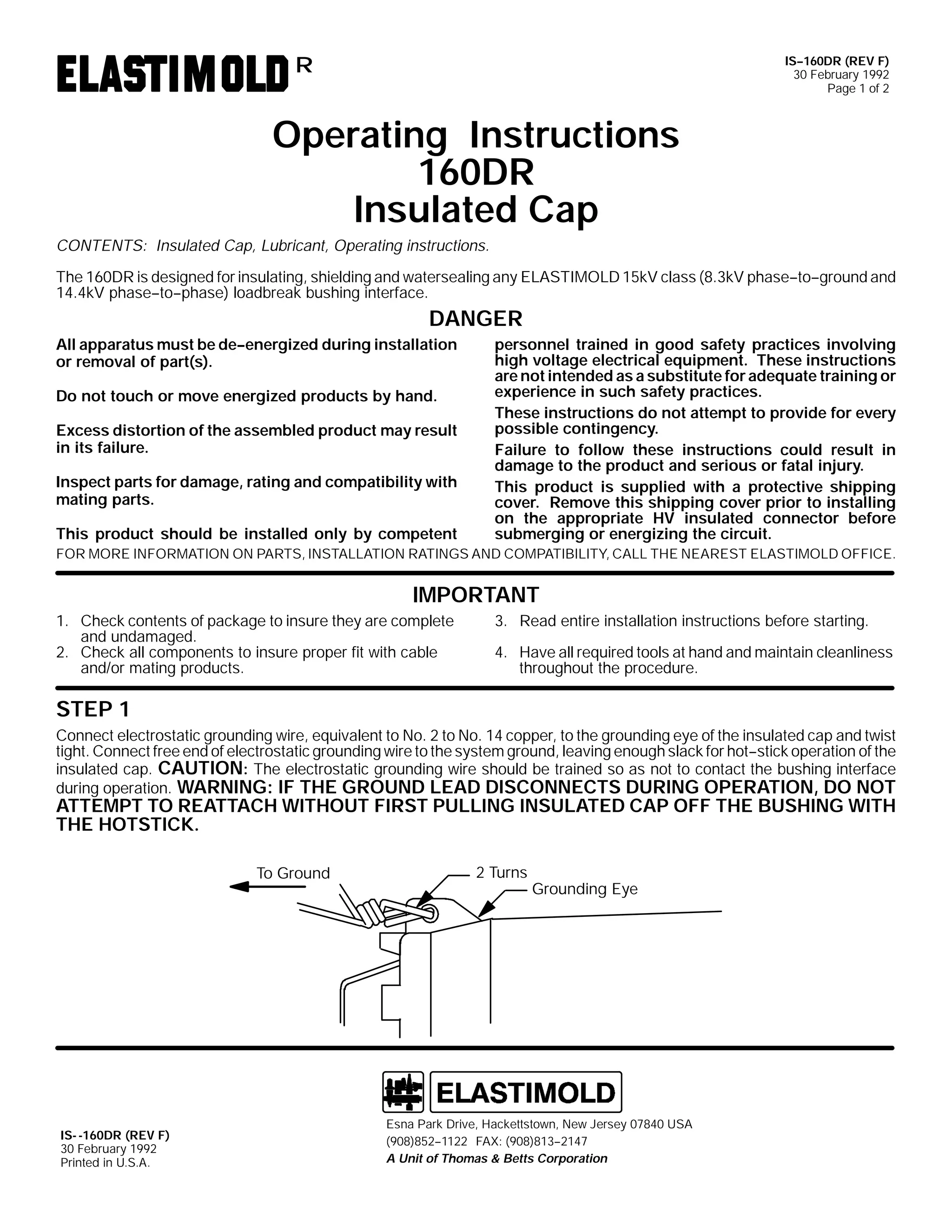
67(3 4
&RQQHFW IUHH HQG RI HOHFWURVWDWLF JURXQGLQJ ZLUH WR WKH VVWHP JURXQG/ OHDYLQJ HQRXJK VODFN IRU KRW0 0VWLFN RSHUDWLRQ RI WKH
LQVXODWHG FDS1 &DXWLRQ/ 7KH HOHFWURVWDWLF JURXQGLQJ ZLUH VKRXOG EH WUDLQHG VR DV QRW WR FRQWDFW WKH EXVKLQJ LQWHUIDFH
GXULQJ RSHUDWLRQ1 :DUQLQJ= ,I WKH JURXQG OHDG GLVFRQQHFWV GXULQJ RSHUDWLRQ/ GR QRW DWWHPSW WR UHDWWDFK ZLWKRXW ILUVW
SXOOLQJ LQVXODWHG FDS RII WKH EXVKLQJ ZLWK WKH KRWVWLFN1
7R *URXQG
*URXQGLQJ (H
3URWHFWLYH &RYHU
,60 049;'5*
63 $SULO 4<<5
3ULQWHG LQ 8161$1
5RXWH 57/ +DFNHWWVWRZQ/ 1HZ -HUVH 3:;73 86$
+<3;,;850 04455 )$;= +<3;,;850 0948;
$ 8QLW RI (DJOH ,QGXVWULHV/ ,QF1](https://image.slidesharecdn.com/elastimold-140130102426-phpapp02/75/Elastimold-Connectors-Loadbreak-Deadbreak-Elbow-Bolted-Tee-Connectors-HV-MV-700-Series-146-2048.jpg)
![,60 049;'5*
63 $SULO 4<<5
3DJH 5
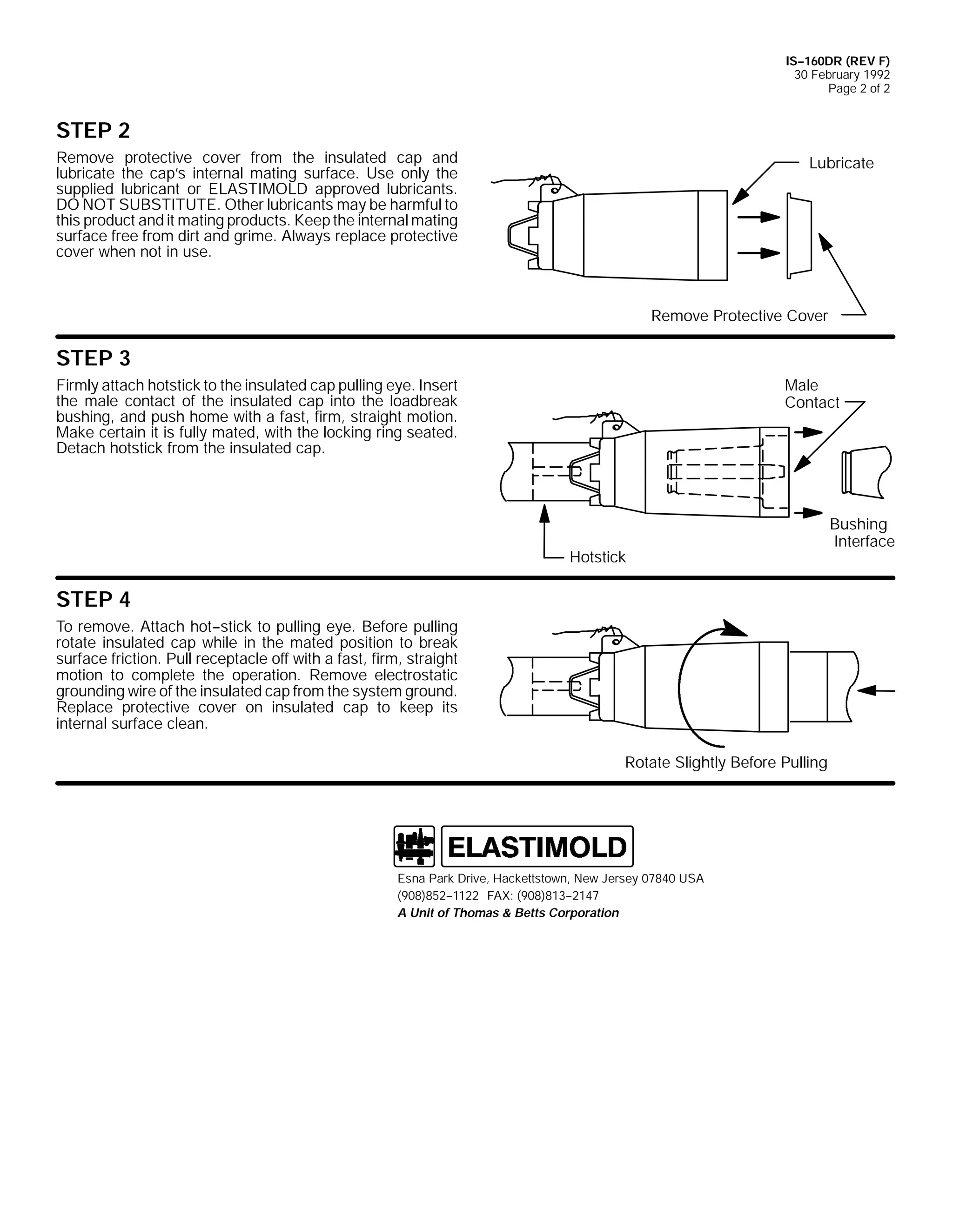
67(3 5
5HPRYH SURWHFWLYH FDS IURP WKH LQVXODWHG FDS DQG OXEUL0
FDWH WKH UHFHSWDFOH*V LQWHUQDO PDWLQJ VXUIDFH1 8VH RQO
(/$67,02/' DSSURYHG OXEULFDQWV1 '2 127 68%67,0
787(1 2WKHU OXEULFDQWV PD EH KDUPIXO WR WKLV SURGXFW DQG
LW PDWLQJ SURGXFWV1 .HHS WKH LQWHUQDO PDWLQJ VXUIDFH IUHH
IURP GLUW DQG JULPH1 $OZDV UHSODFH SURWHFWLYH FRYHU ZKHQ
QRW LQ XVH1
/XEULFDWH
5HPRYH 3URWHFWLYH &RYHU
67(3 6
)LUPO DWWDFK KRWVWLFN WR WKH LQVXODWHG FDS SXOOLQJ HH1 ,Q0
VHUW WKH PDOH FRQWDFW RI WKH LQVXODWHG FDS LQWR WKH
ORDGEUHDN EXVKLQJ/ DQG SXVK KRPH ZLWK D IDVW/ ILUP/
VWUDLJKW PRWLRQ1 0DNH FHUWDLQ LW LV IXOO PDWHG/ ZLWK WKH ORFN0
LQJ ULQJ VHDWHG1 'HWDFK KRWVWLFN IURP WKH LQVXODWHG FDS1
0DOH
&RQWDFW
%XVKLQJ ,QWHUIDFH
+RWVWLFN
67(3 7
7R UHPRYH1 $WWDFK KRW0 0VWLFN WR SXOOLQJ HH1 %HIRUH SXOOLQJ
URWDWH LQVXODWHG FDS ZKLOH LQ WKH PDWHG SRVLWLRQ WR EUHDN
VXUIDFH IULFWLRQ1 3XOO UHFHSWDFOH RII ZLWK D IDVW/ ILUP/ VWUDLJKW
PRWLRQ WR FRPSOHWH WKH RSHUDWLRQ1 5HPRYH HOHFWURVWDWLF
JURXQGLQJ ZLUH RI WKH LQVXODWHG FDS IURP WKH VVWHP
JURXQG1 5HSODFH SURWHFWLYH FDS RQ LQVXODWHG FDS WR NHHS LWV
LQWHUQDO VXUIDFH FOHDQ1
5RWDWH 6OLJKWO %HIRUH 3XOOLQJ
92/7$*( 7(67
%XVKLQJ
7KH (/$67,02/' 49;'5* LQVXODWHG FDS LV HTXLSSHG ZLWK DQ LQWHJUDO FDSDFLWDQFH WHVW SRLQW WKDW FDQ EH XVHG WR HVWDEOLVK ZKHWKHU RU QRW WKH FLUFXLW LV HQHU0
JL]HG1 :KHQ XVLQJ WKH WHVW SRLQW/ FRPSOHWH WKH IROORZLQJ VWHSV=
41
5HPRYH WHVW SRLQW FDS ZLWK D KRWVWLFN1 :KHQ UHPRYLQJ FDS/ 3((/ 2)) $7 $1 $1*/( UDWKHU WKDQ SXOOLQJ GLUHFWO LQ OLQH ZLWK WKH WHVW
SRLQW DVVHPEO1
51
8VLQJ D VXLWDEOH VHQVLQJ GHYLFH/ SURFHHG WR GHWHUPLQH LI FDEOH LV HQHUJL]HG1 '2 127 86( &219(17,21$/ 92/7$*(
0($685,1* (48,30(171
:$51,1*= 7+( 92/7$*( 7(67 32,17 ,6 $ &$3$&,7$1&( '(9,&(/ ,7 ,6 127 ',5(&7/< &211(&7(' 72 7+( &21'8&0 0
7251 &217$0,1$7,21= 02,6785(/ ',57/ (7&1/ $5281' 7+( 7(67 32,17/ 25 86( 2) 7+( :521* 0($685,1*
(48,30(17 &$1 3529,'( $ )$/6( l12 92/7$*(l ,1',&$7,21 21 $1 (1(5*,=(' ,168/$7(' &$31 72 35(9(17
6(5,286 25 )$7$/ ,1-85< 75($7 7+( ,168/$7(' &$3 $6 (1(5*,=(' 817,/ 7+( l12 92/7$*(l 7(67 32,17 ,1',0 0
&$7,21 ,6 &21),50(' %< 27+(5 0($161
61
$IWHU YROWDJH GHWHFWLRQ KDV EHHQ PDGH/ FOHDQ DQG OXEULFDWH WKH LQVLGH VXUIDFH RI WKH FDS ZLWK VLOLFRQH JUHDVH DQG UHSODFH LW RQ WKH
WHVW SRLQW1
5RXWH 57/ +DFNHWWVWRZQ/ 1HZ -HUVH 3:;73 86$
+<3;, ;850 04455 )$;= +<3;, ;850 0948;
$ 8QLW RI (DJOH ,QGXVWULHV/ ,QF1](https://image.slidesharecdn.com/elastimold-140130102426-phpapp02/75/Elastimold-Connectors-Loadbreak-Deadbreak-Elbow-Bolted-Tee-Connectors-HV-MV-700-Series-147-2048.jpg)

![9
,60 05:7'5*26:9'5*
63 $SULO 4<<5
3DJH 4
2SHUDWLQJ ,QVWUXFWLRQV
5:7'5*26:9'5*
,QVXODWHG &DS ZLWK 7HVW 3RLQW ) *URXQG /HDG
&217(176= ,QVXODWHG &DS ZLWK WHVW SRLQW/ *URXQG /HDG/ /XEULFDQW/ 2SHUDWLQJ ,QVWUXFWLRQV
7KH 5:7'5* LV GHVLJQHG IRU LQVXODWLQJ/ VKLHOGLQJ DQG ZDWHUVHDOLQJ DQ (/$67,02/' 58N9 FODVV +4815N9 SKDVH0 0WR0 0
JURXQG DQG 5916N9 SKDVH0 0WR0 0SKDVH, ORDGEUHDN EXVKLQJ LQWHUIDFH1 7KH 6:9'5* LV GHVLJQHG IRU LQVXODWLQJ/ VKLHOGLQJ DQG
ZDWHUVHDOLQJ DQ (ODVWLPROG 68N9 FODVV +5414N9 SKDVH0 0WR0 0JURXQG DQG 6919N9 SKDVH0 0WR0 0SKDVH, ORDGEUHDN EXVKLQJ LQ0
WHUIDFH1
'$1*(5
$OO DSSDUDWXV PXVW EH GH0 0HQHUJL]HG GXULQJ LQVWDOODWLRQ
RU UHPRYDO RI SDUW+V,1
SHUVRQQHO WUDLQHG LQ JRRG VDIHW SUDFWLFHV LQYROYLQJ
KLJK YROWDJH HOHFWULFDO HTXLSPHQW1 7KHVH LQVWUXFWLRQV
DUH QRW LQWHQGHG DV D VXEVWLWXWH IRU DGHTXDWH WUDLQLQJ RU
H[SHULHQFH LQ VXFK VDIHW SUDFWLFHV1
'R QRW WRXFK RU PRYH HQHUJL]HG SURGXFWV E KDQG1
7KHVH LQVWUXFWLRQV GR QRW DWWHPSW WR SURYLGH IRU HYHU
SRVVLEOH FRQWLQJHQF1
([FHVV GLVWRUWLRQ RI WKH DVVHPEOHG SURGXFW PD UHVXOW
LQ LWV IDLOXUH1
)DLOXUH WR IROORZ WKHVH LQVWUXFWLRQV FRXOG UHVXOW LQ GDP0
DJH WR WKH SURGXFW DQG VHULRXV RU IDWDO LQMXU1
,QVSHFW SDUWV IRU GDPDJH/ UDWLQJ DQG FRPSDWLELOLW ZLWK
7KLV SURGXFW LV VXSSOLHG ZLWK D SURWHFWLYH VKLSSLQJ FRY0
PDWLQJ SDUWV1
HU1 5HPRYH WKLV VKLSSLQJ FRYHU SULRU WR LQVWDOOLQJ RQ WKH
DSSURSULDWH +9 LQVXODWHG FRQQHFWRU EHIRUH VXEPHUJ0
LQJ RU HQHUJL]LQJ WKH FLUFXLW1
7KLV SURGXFW VKRXOG EH LQVWDOOHG RQO E FRPSHWHQW
)25 025( ,1)250$7,21 21 3$576/ ,167$//$7,21 5$7,1*6 $1' &203$7,%,/,7</ &$// 7+( 1($5(67 (/$60
7,02/' 2)),&(1
,03257$17
41 &KHFN FRQWHQWV RI SDFNDJH WR LQVXUH WKH DUH FRP0 0
SOHWH DQG XQGDPDJHG1
51 &KHFN DOO FRPSRQHQWV WR LQVXUH SURSHU ILW ZLWK FDEOH
DQG2RU PDWLQJ SURGXFWV1
61 5HDG HQWLUH LQVWDOODWLRQ LQVWUXFWLRQV EHIRUH VWDUWLQJ1
71 +DYH DOO UHTXLUHG WRROV DW KDQG DQG PDLQWDLQ FOHDQOL0 0
QHVV WKURXJKRXW WKH SURFHGXUH1
67(3 4
&RQQHFW IUHH HQG RI HOHFWURVWDWLF JURXQGLQJ ZLUH WR WKH VVWHP JURXQG/ OHDYLQJ HQRXJK VODFN IRU KRW0 0VWLFN RSHUDWLRQ RI WKH
LQVXODWHG FDS1 &DXWLRQ/ 7KH HOHFWURVWDWLF JURXQGLQJ ZLUH VKRXOG EH WUDLQHG VR DV QRW WR FRQWDFW WKH EXVKLQJ LQWHUIDFH
GXULQJ RSHUDWLRQ1 :DUQLQJ= ,I WKH JURXQG OHDG GLVFRQQHFWV GXULQJ RSHUDWLRQ/ GR QRW DWWHPSW WR UHDWWDFK ZLWKRXW ILUVW
SXOOLQJ LQVXODWHG FDS RII WKH EXVKLQJ ZLWK WKH KRWVWLFN1
7R *URXQG
*URXQGLQJ (H
3URWHFWLYH &RYHU
,60 05:7'5*26:9'5*
63 $SULO 4<<5
3ULQWHG LQ 8161$1
5RXWH 57/ +DFNHWWVWRZQ/ 1HZ -HUVH 3:;73 86$
+<3;,;850 04455 )$;= +<3;,;850 0948;
$ 8QLW RI (DJOH ,QGXVWULHV/ ,QF1](https://image.slidesharecdn.com/elastimold-140130102426-phpapp02/75/Elastimold-Connectors-Loadbreak-Deadbreak-Elbow-Bolted-Tee-Connectors-HV-MV-700-Series-150-2048.jpg)
![,60 05:7'5*26:9'5*
63 $SULO 4<<5
3DJH 5
67(3 5
5HPRYH SURWHFWLYH FDS IURP WKH LQVXODWHG FDS DQG OXEUL0
FDWH WKH UHFHSWDFOH*V LQWHUQDO PDWLQJ VXUIDFH1 8VH RQO
(/$67,02/' DSSURYHG OXEULFDQWV1 '2 127 68%67,0
787(1 2WKHU OXEULFDQWV PD EH KDUPIXO WR WKLV SURGXFW DQG
LW PDWLQJ SURGXFWV1 .HHS WKH LQWHUQDO PDWLQJ VXUIDFH IUHH
IURP GLUW DQG JULPH1 $OZDV UHSODFH SURWHFWLYH FRYHU ZKHQ
QRW LQ XVH1
/XEULFDWH
5HPRYH 3URWHFWLYH &RYHU
67(3 6
)LUPO DWWDFK KRWVWLFN WR WKH LQVXODWHG FDS SXOOLQJ HH1 ,Q0
VHUW WKH PDOH FRQWDFW RI WKH LQVXODWHG FDS LQWR WKH
ORDGEUHDN EXVKLQJ/ DQG SXVK KRPH ZLWK D IDVW/ ILUP/
VWUDLJKW PRWLRQ1 0DNH FHUWDLQ LW LV IXOO PDWHG/ ZLWK WKH ORFN0
LQJ ULQJ VHDWHG1 'HWDFK KRWVWLFN IURP WKH LQVXODWHG FDS1
0DOH
&RQWDFW
+RWVWLFN
%XVKLQJ ,QWHUIDFH
67(3 7
7R UHPRYH1 $WWDFK KRW0 0VWLFN WR SXOOLQJ HH1 %HIRUH SXOOLQJ
URWDWH LQVXODWHG FDS ZKLOH LQ WKH PDWHG SRVLWLRQ WR EUHDN
VXUIDFH IULFWLRQ1 3XOO UHFHSWDFOH RII ZLWK D IDVW/ ILUP/ VWUDLJKW
PRWLRQ WR FRPSOHWH WKH RSHUDWLRQ1 5HPRYH HOHFWURVWDWLF
JURXQGLQJ ZLUH RI WKH LQVXODWHG FDS IURP WKH VVWHP
JURXQG1 5HSODFH SURWHFWLYH FDS RQ LQVXODWHG FDS WR NHHS LWV
LQWHUQDO VXUIDFH FOHDQ1
5RWDWH 6OLJKWO %HIRUH 3XOOLQJ
92/7$*( 7(67
%XVKLQJ
7KH (/$67,02/' 5:7'5* DQG 6:9'5* LQVXODWHG FDSV DUH HTXLSSHG ZLWK DQ LQWHJUDO FDSDFLWDQFH WHVW SRLQW WKDW FDQ EH XVHG WR HVWDEOLVK ZKHWKHU RU QRW WKH
FLUFXLW LV HQHUJL]HG1 :KHQ XVLQJ WKH WHVW SRLQW/ FRPSOHWH WKH IROORZLQJ VWHSV=
41
5HPRYH WHVW SRLQW FDS ZLWK D KRWVWLFN1 :KHQ UHPRYLQJ FDS/ 3((/ 2)) $7 $1 $1*/( UDWKHU WKDQ SXOOLQJ GLUHFWO LQ OLQH ZLWK WKH WHVW
SRLQW DVVHPEO1
51
8VLQJ D VXLWDEOH VHQVLQJ GHYLFH/ SURFHHG WR GHWHUPLQH LI FDEOH LV HQHUJL]HG1 '2 127 86( &219(17,21$/ 92/7$*(
0($685,1* (48,30(171
:$51,1*= 7+( 92/7$*( 7(67 32,17 ,6 $ &$3$&,7$1&( '(9,&(/ ,7 ,6 127 ',5(&7/< &211(&7(' 72 7+( &21'8&0 0
7251 &217$0,1$7,21= 02,6785(/ ',57/ (7&1/ $5281' 7+( 7(67 32,17/ 25 86( 2) 7+( :521* 0($685,1*
(48,30(17 &$1 3529,'( $ )$/6( l12 92/7$*(l ,1',&$7,21 21 $1 (1(5*,=(' ,168/$7(' &$31 72 35(9(17
6(5,286 25 )$7$/ ,1-85< 75($7 7+( ,168/$7(' &$3 $6 (1(5*,=(' 817,/ 7+( l12 92/7$*(l 7(67 32,17 ,1',0 0
&$7,21 ,6 &21),50(' %< 27+(5 0($161
61
$IWHU YROWDJH GHWHFWLRQ KDV EHHQ PDGH/ FOHDQ DQG OXEULFDWH WKH LQVLGH VXUIDFH RI WKH FDS ZLWK VLOLFRQH JUHDVH DQG UHSODFH LW RQ WKH
WHVW SRLQW1
5RXWH 57/ +DFNHWWVWRZQ/ 1HZ -HUVH 3:;73 86$
+<3;,;850 04455 )$;= +<3;,;850 0948;
$ 8QLW RI (DJOH ,QGXVWULHV/ ,QF1](https://image.slidesharecdn.com/elastimold-140130102426-phpapp02/75/Elastimold-Connectors-Loadbreak-Deadbreak-Elbow-Bolted-Tee-Connectors-HV-MV-700-Series-151-2048.jpg)


![9
,60 049326:3*/5 +5HY $,
63 $SULO 4<<5
3DJH 4 RI 6
,QVWDOODWLRQ ) 2SHUDWLQJ ,QVWUXFWLRQV
493*/5 ) 6:3*/5
*5281',1* (/%2:
&217(176=
*URXQGLQJ (OERZ/ /XEULFDQW +'2 127 68%67,787(,/ ,QVWDOODWLRQ22SHUDWLQJ ,QVWUXFWLRQ
7KH JURXQGLQJ HOERZ LV GHVLJQHG WR SURYLGH SOXJ0 0LQ/ YLVLEOH JURXQGLQJ IRU 8' VVWHPV1 7KH 493*/5 SURYLGHV DQ RSHUDWLQJ
LQWHUIDFH IRU FRQQHFWLQJ WR DQ $16,2,((( 67' 6;9 )LJ1 8/ 48N9 FODVV +QRPLQDO ;16N9 SKDVH0 0WR0 0JURXQG DQG 4717N9 SKDVH0 0
WR0 0SKDVH, 533 DPSHUH ORDGEUHDN EXVKLQJ RU DFFHVVRU GHYLFH ZLWK IDXOW FORVH UDWLQJ RI 43/333 DPSHUHV/ VPPHWULFDO1
7KH 6:3*/5 SURYLGHV DQ RSHUDWLQJ LQWHUIDFH IRU FRQQHFWLQJ WR DQ $16,2,((( 67' 6;9 )LJ1 :/ 58N9 FODVV +QRPLQDO 4815N9
SKDVH0 0WR0 0JURXQG DQG 5916N9 SKDVH0 0WR0 0SKDVH, RU 68N9 FODVV +QRPLQDO 5414N9 SKDVH0 0WR0 0JURXQG DQG 6919N9 SKDVH0 0
WR0 0SKDVH, 533 DPSHUH ORDGEUHDN EXVKLQJ RU DFFHVVRU GHYLFH ZLWK IDXOW FORVH UDWLQJ RI 43/333 DPSHUHV/ VPPHWULFDO1
'$1*(5
$OO DSSDUDWXV PXVW EH GH0 0HQHUJL]HG GXULQJ LQVWDOODWLRQ
RU UHPRYDO RI SDUW+V,1
'R QRW WRXFK RU PRYH HQHUJL]HG SURGXFWV E KDQG1
([FHVV GLVWRUWLRQ RI WKH DVVHPEOHG SURGXFW PD UHVXOW
LQ LWV IDLOXUH1
,QVSHFW SDUWV IRU GDPDJH/ UDWLQJ DQG FRPSDWLELOLW ZLWK
PDWLQJ SDUWV1
7KLV SURGXFW VKRXOG EH LQVWDOOHG RQO E FRPSHWHQW
SHUVRQQHO WUDLQHG LQ JRRG VDIHW SUDFWLFHV LQYROYLQJ
KLJK YROWDJH HOHFWULFDO HTXLSPHQW1 7KHVH LQVWUXFWLRQV
DUH QRW LQWHQGHG DV D VXEVWLWXWH IRU DGHTXDWH WUDLQLQJ RU
H[SHULHQFH LQ VXFK VDIHW SUDFWLFHV1
7KHVH LQVWUXFWLRQV GR QRW DWWHPSW WR SURYLGH IRU HYHU
SRVVLEOH FRQWLQJHQF1
)DLOXUH WR IROORZ WKHVH LQVWUXFWLRQV ZLOO UHVXOW LQ GDPDJH
WR WKH SURGXFW DQG VHULRXV RU IDWDO LQMXU1
)25 025( ,1)250$7,21 21 3$576/ ,167$//$7,21 5$7,1*6 $1' &203$7,%,/,7</ &$// 7+( 1($5(67 (/$67,02/' 2)),&(1
,03257$17
3URWHFWLYH
&DS
41 &KHFN FRQWHQWV RI SDFNDJH WR LQVXUH WKH DUH FRPSOHWH
DQG XQGDPDJHG1
51 &KHFN DOO FRPSRQHQWV WR LQVXUH SURSHU ILW ZLWK FDEOH
DQG2RU PDWLQJ SURGXFWV1
:DUQLQJ
7DJ
61 5HDG HQWLUH LQVWDOODWLRQ LQVWUXFWLRQV EHIRUH VWDUWLQJ1
71 +DYH DOO UHTXLUHG WRROV DW KDQG DQG PDLQWDLQ FOHDQOLQHVV
WKURXJKRXW WKH SURFHGXUH1
,60 049326:3*/5 +5HY $,
63 $SULO 4<<5
3ULQWHG LQ 8161$1
*URXQG /HDG
(VQD 3DUN 'ULYH/ +DFNHWWVWRZQ/ 1HZ -HUVH 3:;73 86$
+<3;,;850 04455 )$;= +<3;,;460 0547:
$ 8QLW RI 7KRPDV ) %HWWV &RUSRUDWLRQ
*URXQGLQJ
(OERZ
2SHUDWLQJ
(H](https://image.slidesharecdn.com/elastimold-140130102426-phpapp02/75/Elastimold-Connectors-Loadbreak-Deadbreak-Elbow-Bolted-Tee-Connectors-HV-MV-700-Series-162-2048.jpg)
![,60 049326:3*/5 +5HY $,
63 $SULO 4<<5
3DJH 5 RI 6
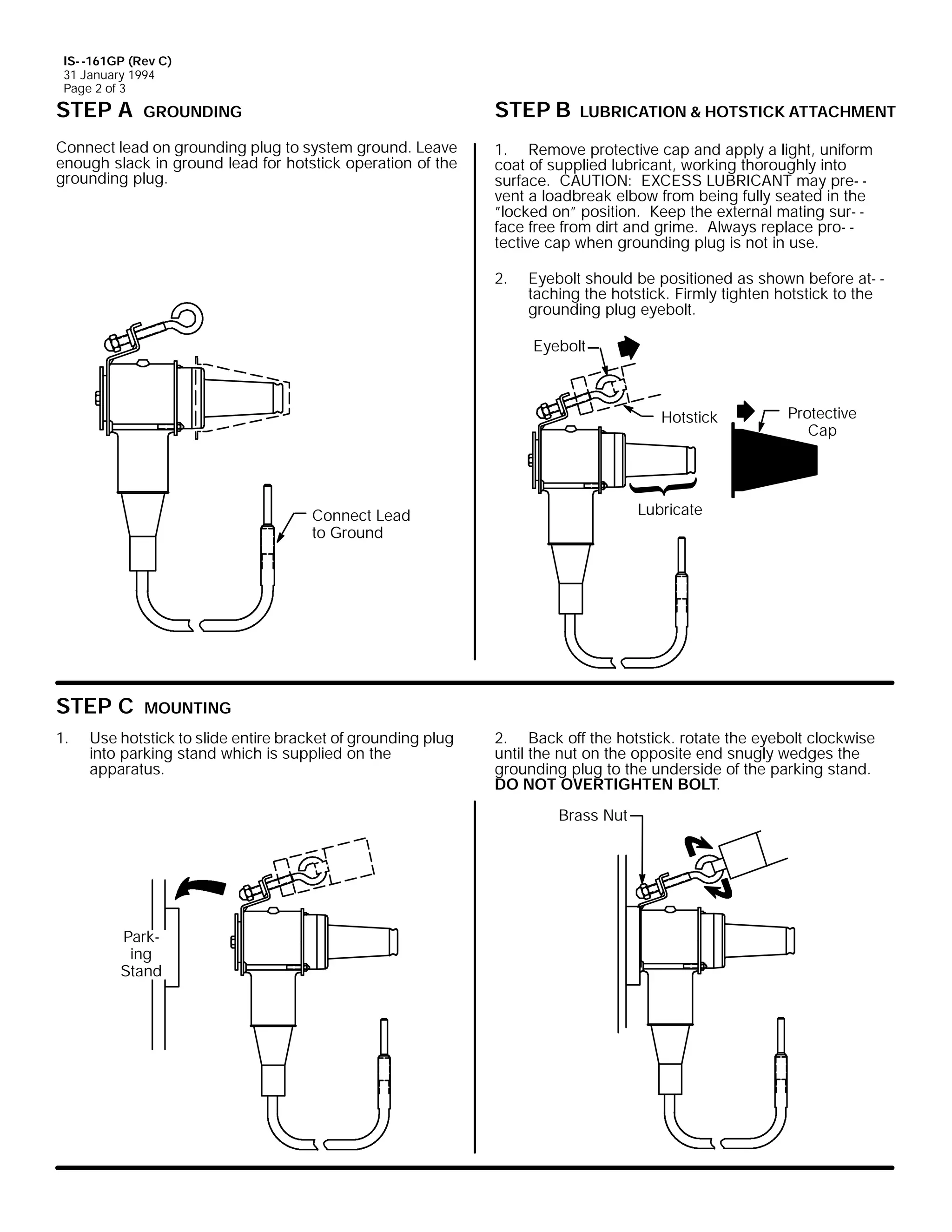
67(3 $ *5281',1*
&RQQHFW OHDG RQ JURXQGLQJ HOERZ WR VVWHP JURXQG1
/HDYH HQRXJK VODFN LQ JURXQG OHDG IRU KRWVWLFN RSHUDWLRQ RI
WKH JURXQGLQJ HOERZ1
&RQQHFW /HDG
WR *URXQG
67(3 % /8%5,&$7,21
5HPRYH SURWHFWLYH FDS DQG DSSO D OLJKW/ XQLIRUP FRDW RI
VXSSOLHG OXEULFDQW/ ZRUNLQJ WKRURXJKO LQWR VXUIDFH1
&$87,21=
(;&(66 /8%5,&$17 PD SUHYHQW WKH
JURXQGLQJ HOERZ IURP EHLQJ IXOO VHDWHG LQ WKH lORFNHG RQl
SRVLWLRQ1 .HHS WKH LQWHUQDO PDWLQJ VXUIDFH IUHH IURP GLUW
DQG JULPH1
5HPRYH
3URWHFWLYH
&DS
/XEULFDWH
,03257$17= 'R QRW LQVHUW JURXQGLQJ HOERZ LQWR EXVKLQJ XQOHVV FLUFXLW KDV EHHQ WHVWHG DQG VKRZQ WR EH lGH0 0HQHU0
JL]HGl1
67(3 & 35(3$5$7,21
(1685( 7+$7 7+( 6<67(0 ,6 '(0 0(1(5*,=(' :,7+ (,7+(5 2) 7+( )2//2:,1* 352&('85(6=
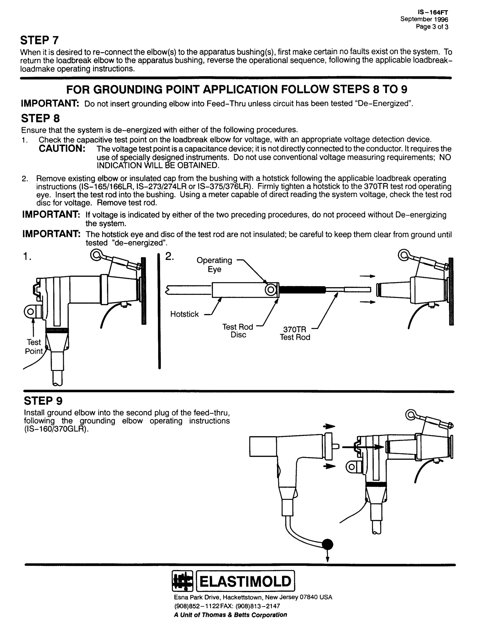
41 &KHFN WKH FDSDFLWLYH WHVW SRLQW RQ WKH ORDGEUHDN HOERZ IRU YROWDJH/ ZLWK DQ DSSURSULDWH YROWDJH GHWHFWLRQ GHYLFH1
&$87,21= 7KH YROWDJH WHVW SRLQW LV D FDSDFLWDQFH GHYLFH> LW LV QRW GLUHFWO FRQQHFWHG WR WKH FRQGXFWRU1 ,W UHTXLUHV WKH
XVH RI VSHFLDOO GHVLJQHG LQVWUXPHQWV1 12 ,1',&$7,21 :,// %( 2%7$,1(' 81/(66 7+( &255(&7 722/ ,6 86('1
51 5HPRYH H[LVWLQJ HOERZ RU LQVXODWHG FDS IURP WKH EXVKLQJ ZLWK D KRWVWLFN IROORZLQJ WKH DSSOLFDEOH ORDGEUHDN RSHUDWLQJ
LQVWUXFWLRQV +,60 049:249;/5/ ,60 05:625:7/5 RU ,60 06:826:9/5,1 )LUPO WLJKWHQ D KRWVWLFN WR WKH 6:375 WHVW URG RSHUDW0 0
LQJ HH1 ,QVHUW WKH WHVW URG LQWR WKH EXVKLQJ1 8VLQJ D PHWHU FDSDEOH RI GLUHFW UHDGLQJ WKH VVWHP YROWDJH/ FKHFN WKH
WHVW URG GLVF IRU YROWDJH1 5HPRYH WHVW URG1
,03257$17= ,I YROWDJH LV LQGLFDWHG E HLWKHU RI WKH WZR SUHFHGLQJ SURFHGXUHV/ GR QRW SURFHHG ZLWKRXW GH0 0HQHUJL]LQJ
WKH VVWHP1
&$87,21= 7KH KRWVWLFN HH DQG GLVF RI WKH WHVW URG DUH QRW LQVXODWHG> EH FDUHIXO WR NHHS WKHP FOHDU IURP JURXQG XQWLO
WHVWHG lGH0 0HQHUJL]HGl1
41
51
7HVW
3RLQW
2SHUDWLQJ
(H
6:375
7HVW 5RG
7HVW 5RG
'LVF
+RWVWLFN](https://image.slidesharecdn.com/elastimold-140130102426-phpapp02/75/Elastimold-Connectors-Loadbreak-Deadbreak-Elbow-Bolted-Tee-Connectors-HV-MV-700-Series-163-2048.jpg)
![,60 049326:3*/5 +5HY $,
63 $SULO 4<<5
3DJH 6 RI 6
,) 21( 2) 7+( $%29( 0($685(0(176 ,1',&$7(6 7+( 6<67(0 ,6 '(0 0(1(5*,=(' 352&((' :,7+ 67(3 '1
67(3 ' &211(&7,21
&$87,21= &RQWLQXH WR WUHDW WKH VVWHP DV HQHU0 0
JL]HG XVLQJ D KRWVWLFN IRU DOO RSHUDWLRQV LQ FDVH RI
HUURU RU HTXLSPHQW PDOIXQFWLRQ LQ 6WHS &= '2 127
23(5$7( %< +$1'1
51 )LUPO WLJKWHQ D KRWVWLFN WR WKH JURXQGLQJ HOERZ
RSHUDWLQJ HH1
61 3ODFH WKH JURXQGLQJ HOERZ UHFHSWDFOH DUHD RYHU WKH
EXVKLQJ/ LQVHUWLQJ WKH SUREH LQWR WKH EXVKLQJ XQWLO WKH
ILUVW VOLJKW UHVLVWDQFH LV IHOW1
71 )LUPO WKUXVW WKH JURXQGLQJ HOERZ KRPH ZLWK D IDVW/
VWUDLJKW PRWLRQ/ ZKLFK ZLOO HQJDJH WKH LQWHUQDO ORFN RI
WKH JURXQGLQJ HOERZ LQWR WKH EXVKLQJ LQWHUIDFH1
41
&$87,21= ,QVSHFW JURXQG OHDG IRU SURSHU
FRQQHFWLRQ1 ,I JURXQG OHDG GLVFRQQHFWV GXULQJ
RSHUDWLRQ/ '2 127 DWWHPSW WR UH0 0DWWDFK ZLWKRXW
ILUVW SXOOLQJ JURXQGLQJ HOERZ RII WKH EXVKLQJ ZLWK D
KRWVWLFN1
91 7R UHWXUQ WKH ORDGEUHDN HOERZ WR WKH DSSDUDWXV EXVK0 0
LQJ DQG WR UHPRYH WKH JURXQGLQJ HOERZ/ UHYHUVH WKH
RSHUDWLRQDO VHTXHQFH/ IROORZLQJ WKH DSSOLFDEOH ORDG0 0
EUHDN0 0ORDGPDNH RSHUDWLQJ LQVWUXFWLRQV1
81
+RWVWLFN
*URXQG
(VQD 3DUN 'ULYH/ +DFNHWWVWRZQ/ 1HZ -HUVH 3:;73 86$
+<3;,;850 04455 )$;= +<3;,;460 0547:
$ 8QLW RI 7KRPDV ) %HWWV &RUSRUDWLRQ](https://image.slidesharecdn.com/elastimold-140130102426-phpapp02/75/Elastimold-Connectors-Loadbreak-Deadbreak-Elbow-Bolted-Tee-Connectors-HV-MV-700-Series-164-2048.jpg)

![9
,60 05:7)7
-DQXDU 4<<;
3DJH 4 RI 7
2SHUDWLQJ ,QVWUXFWLRQV
5:7)7
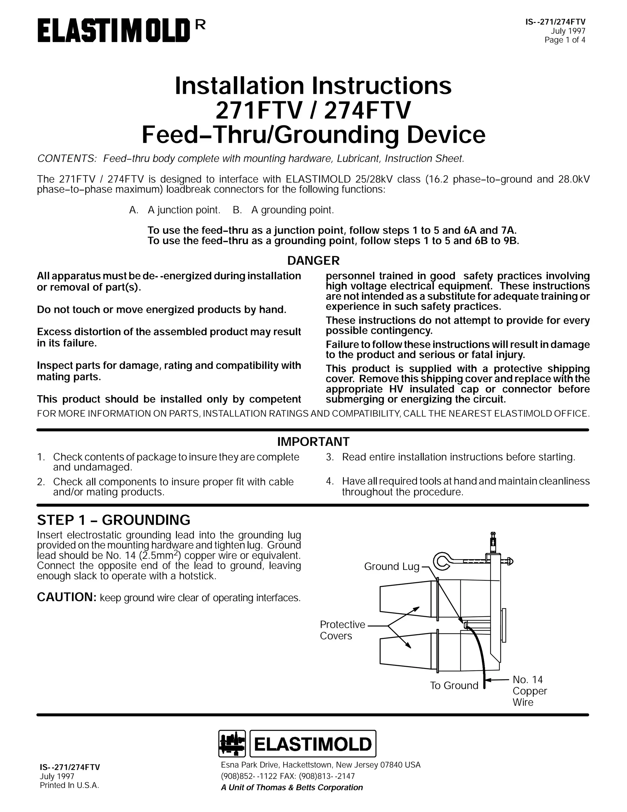
)HHG007KUX2*URXQGLQJ 'HYLFH
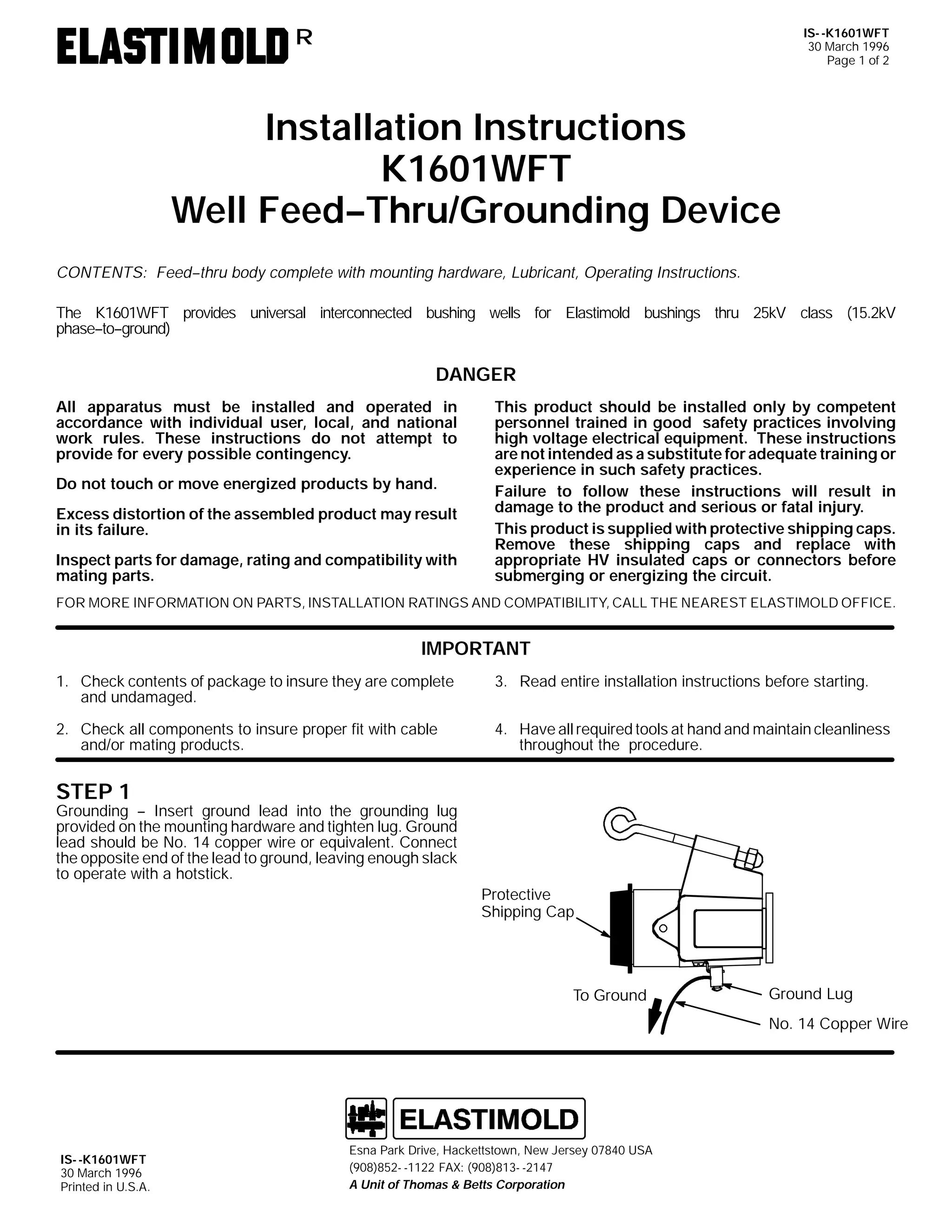
&217(176= )HHG00WKUX ERG FRPSOHWH ZLWK PRXQWLQJ KDUGZDUH/ /XEULFDQW/ 2SHUDWLQJ ,QVWUXFWLRQV1
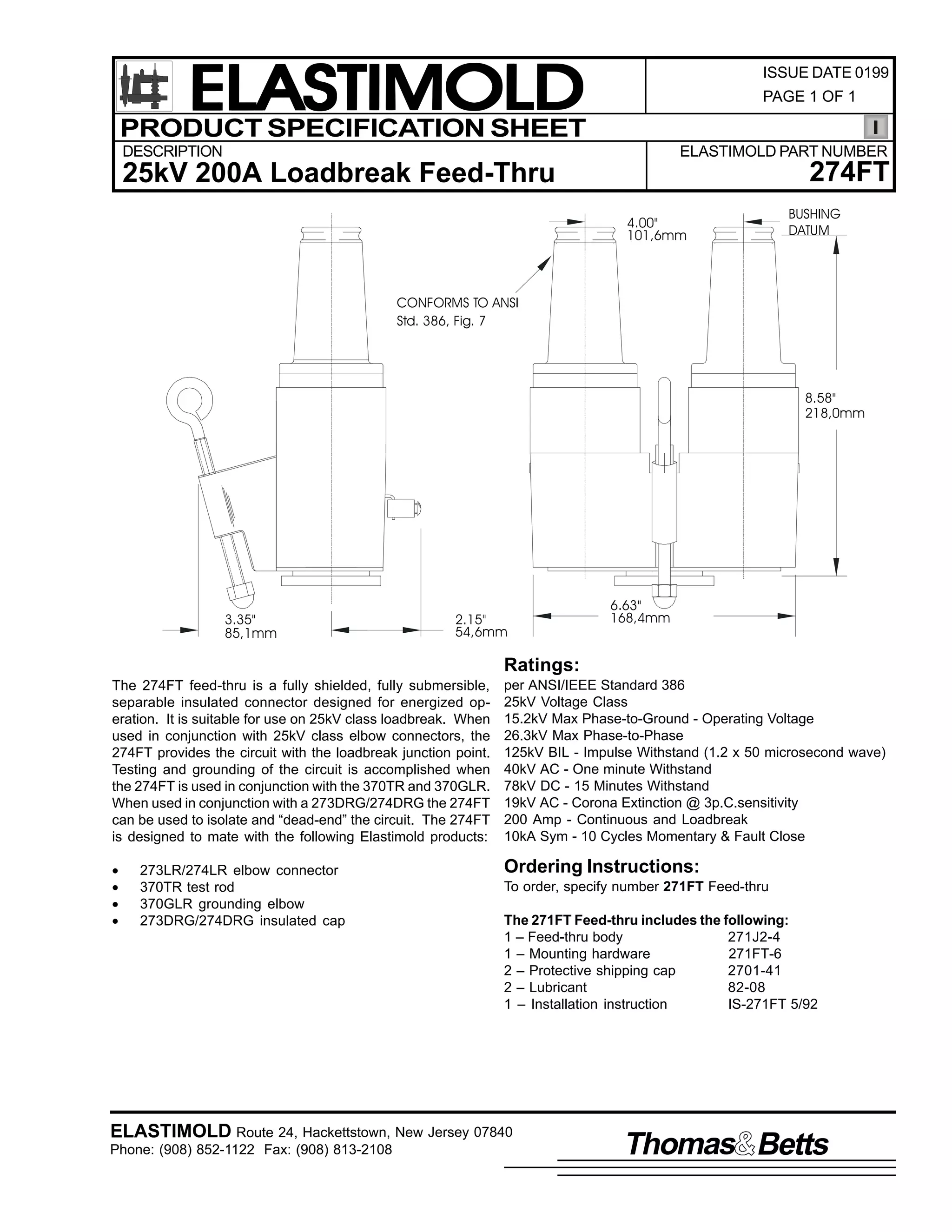
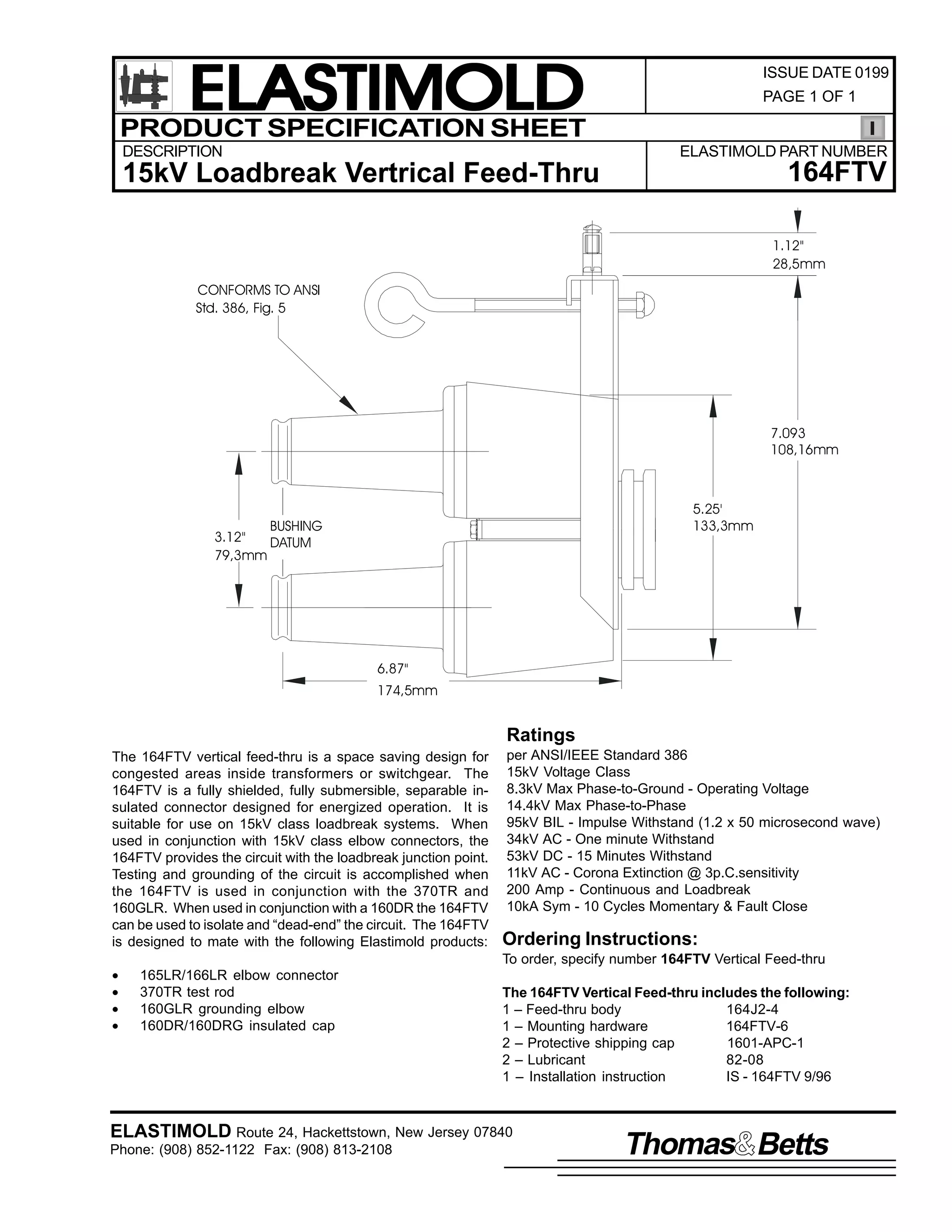
7KH 5:7)7 SURYLGHV LQWHUFRQQHFWHG DSSDUDWXV LQWHUIDFHV IRU (ODVWLPROG 58N9 FODVV +4815N9 SKDVH00WR00JURXQG DQG 5916N9
SKDVH00WR00SKDVH, ORDGEUHDN FRQQHFWLRQV DQG FDQ EH XVHG IRU WKH IROORZLQJ IXQFWLRQV=
$1 $ MXQFWLRQ SRLQW1 %1 $ JURXQGLQJ SRLQW1
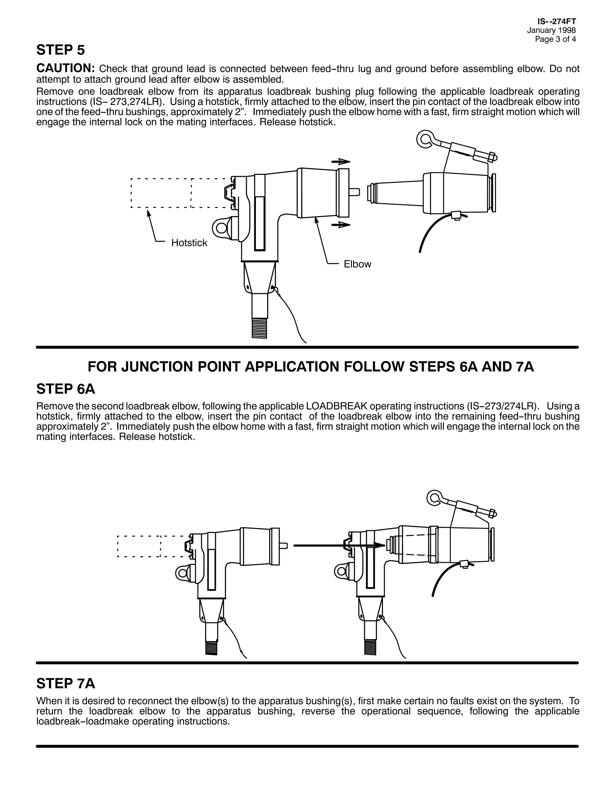
7R XVH WKH IHHG00WKUX DV D MXQFWLRQ SRLQW/ IROORZ VWHSV 4 WR 8 DQG 9$ DQG :$1
7R XVH WKH IHHG00WKUX DV D JURXQGLQJ SRLQW/ IROORZ VWHSV 4 WR 8 DQG 9% WR <%1
'$1*(5
$OO DSSDUDWXV PXVW EH LQVWDOOHG DQG RSHUDWHG LQ
DFFRUGDQFH ZLWK LQGLYLGXDO XVHU/ ORFDO/ DQG QDWLRQDO
ZRUN UXOHV1 7KHVH LQVWUXFWLRQV GR QRW DWWHPSW WR
SURYLGH IRU HYHU SRVVLEOH FRQWLQJHQF1
'R QRW WRXFK RU PRYH HQHUJL]HG SURGXFWV E KDQG1
([FHVV GLVWRUWLRQ RI WKH DVVHPEOHG SURGXFW PD UHVXOW
LQ LWV IDLOXUH1
,QVSHFW SDUWV IRU GDPDJH/ UDWLQJ DQG FRPSDWLELOLW ZLWK
PDWLQJ SDUWV1
7KLV SURGXFW VKRXOG EH LQVWDOOHG RQO E FRPSHWHQW
SHUVRQQHO WUDLQHG LQ JRRG VDIHW SUDFWLFHV LQYROYLQJ
KLJK YROWDJH HOHFWULFDO HTXLSPHQW1 7KHVH LQVWUXFWLRQV
DUH QRW LQWHQGHG DV D VXEVWLWXWH IRU DGHTXDWH WUDLQLQJ RU
H[SHULHQFH LQ VXFK VDIHW SUDFWLFHV1
)DLOXUH WR IROORZ WKHVH LQVWUXFWLRQV FRXOG UHVXOW LQ
GDPDJH WR WKH SURGXFW DQG VHULRXV RU IDWDO LQMXU1
7KLV SURGXFW LV VXSSOLHG ZLWK SURWHFWLYH VKLSSLQJ
FRYHUV1 5HPRYH WKHVH VKLSSLQJ FRYHUV DQG UHSODFH
ZLWK DSSURSULDWH +9 LQVXODWHG FDSV RU FRQQHFWRUV
EHIRUH VXEPHUJLQJ RU HQHUJL]LQJ WKH FLUFXLW1
)25 025( ,1)250$7,21 21 3$576/ ,167$//$7,21 5$7,1*6 $1' &203$7,%,/,7</ &$// 7+( 1($5(67 (/$67,02/' 2)),&(1
,03257$17
41 &KHFN FRQWHQWV RI SDFNDJH WR LQVXUH WKH DUH FRPSOHWH
DQG XQGDPDJHG1
61 5HDG HQWLUH LQVWDOODWLRQ LQVWUXFWLRQV EHIRUH VWDUWLQJ1
51 &KHFN DOO FRPSRQHQWV WR LQVXUH SURSHU ILW ZLWK FDEOH
DQG2RU PDWLQJ SURGXFWV1
71 +DYH DOO UHTXLUHG WRROV DW KDQG DQG PDLQWDLQ FOHDQOLQHVV
WKURXJKRXW WKH SURFHGXUH1
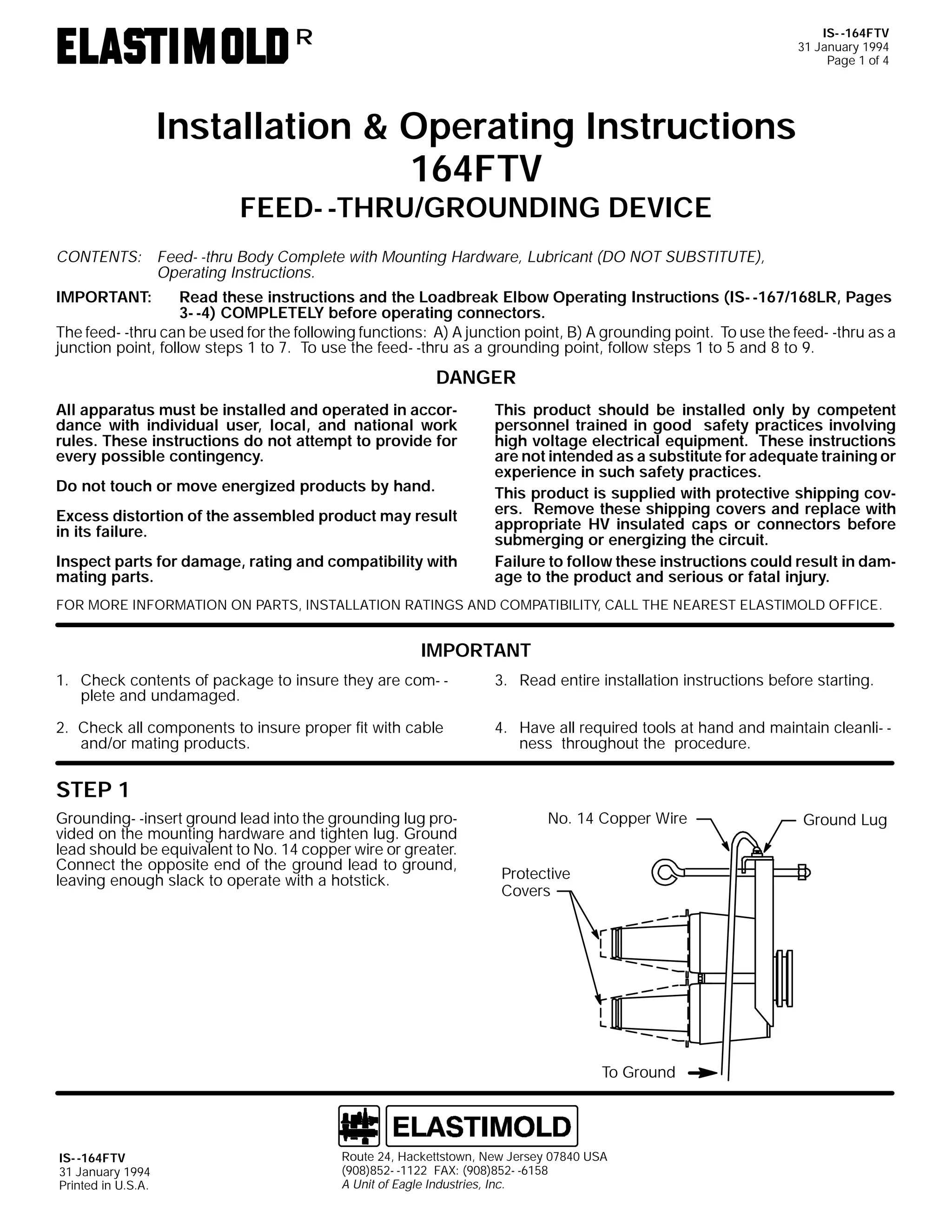
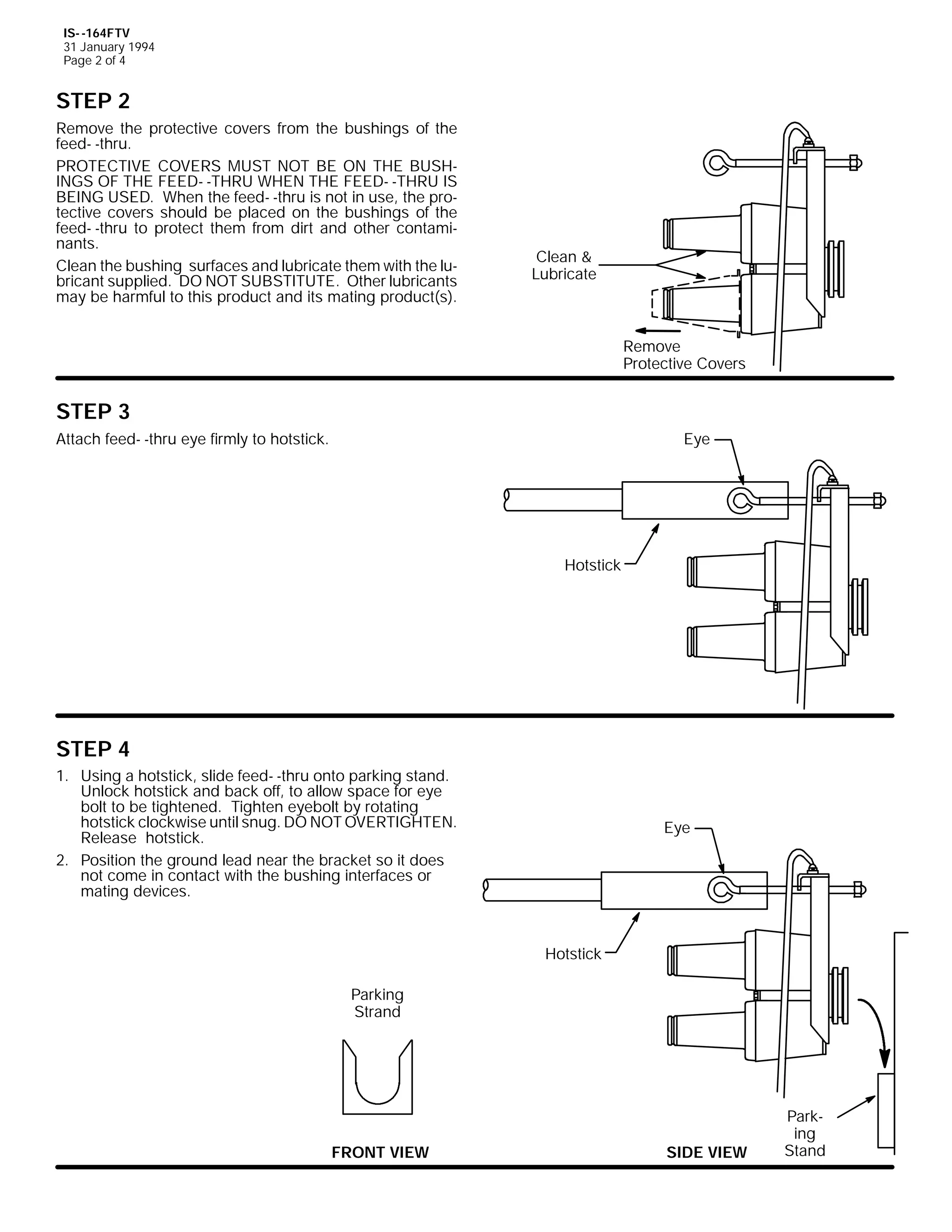
67(3 4
*URXQGLQJ00 ,QVHUW JURXQG OHDG LQWR WKH JURXQGLQJ OXJ
SURYLGHG RQ WKH PRXQWLQJ KDUGZDUH DQG WLJKWHQ OXJ1 *URXQG
OHDG VKRXOG EH 1R1 47 FRSSHU ZLUH RU HTXLYDOHQW1 &RQQHFW
WKH RSSRVLWH HQG RI WKH OHDG WR JURXQG/ OHDYLQJ HQRXJK VODFN
WR RSHUDWH ZLWK D KRWVWLFN1
7R *URXQG
*URXQG /XJ
1R1 47 &RSSHU :LUH
,60 05:7)7
-DQXDU 4<<;
3ULQWHG LQ 8161$1
(VQD 3DUN 'ULYH/ +DFNHWWVWRZQ/ 1HZ -HUVH 3:;73 86$
+<3;,;850 04455 )$;= +<3;,;460 0547:
$ 8QLW RI 7KRPDV ) %HWWV &RUSRUDWLRQ](https://image.slidesharecdn.com/elastimold-140130102426-phpapp02/75/Elastimold-Connectors-Loadbreak-Deadbreak-Elbow-Bolted-Tee-Connectors-HV-MV-700-Series-170-2048.jpg)
![,60 05:7)7
-DQXDU 4<<;
3DJH 7 RI 7
)25 *5281',1* 32,17 $33/,&$7,21 )2//2: 67(36 9% 72 <%
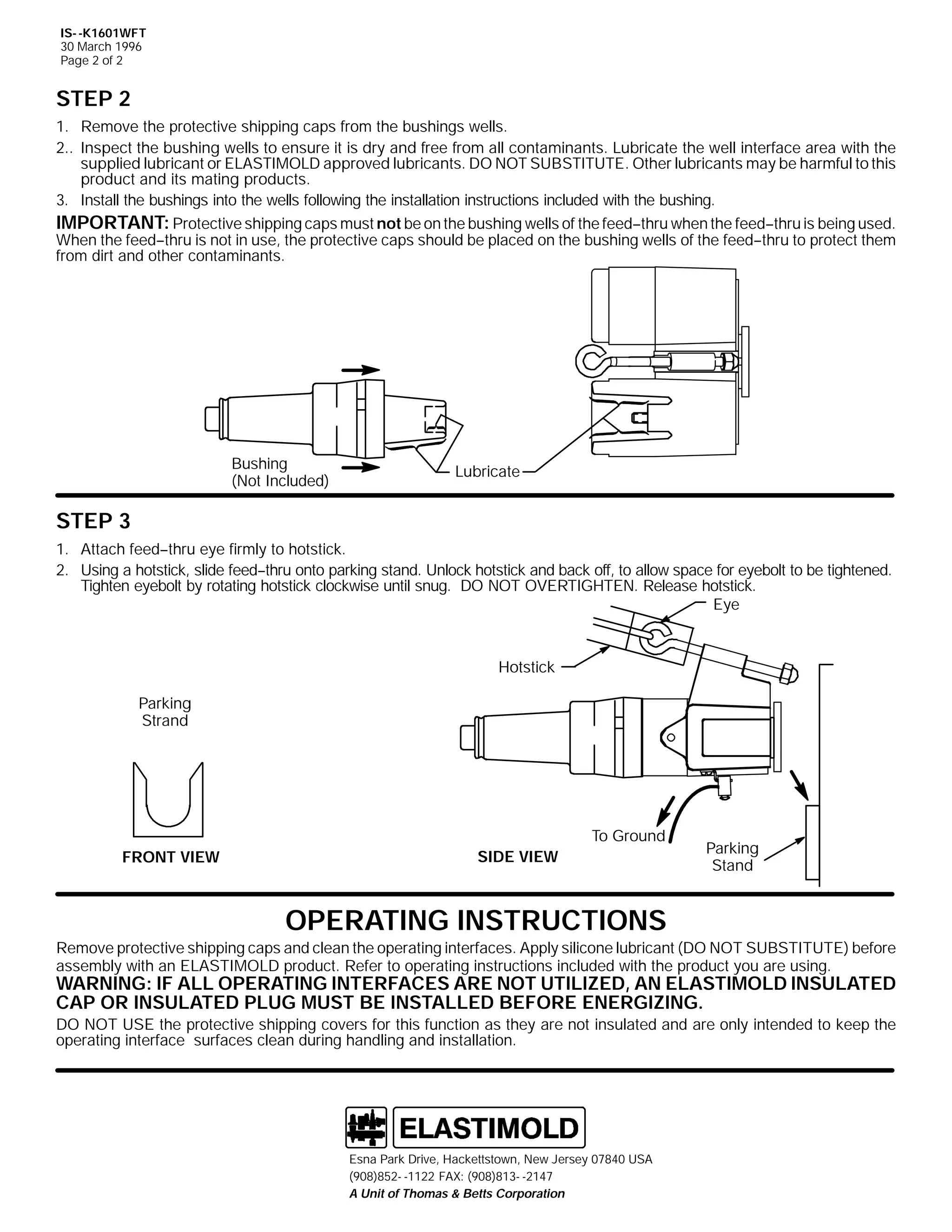
67(3 9%
&RQQHFW OHDG RQ (/$67,02/' 6:3*/5 JURXQGLQJ HOERZ WR
JURXQG1
&$87,21= 'R QRW DWWHPSW WR FRQQHFW WKH JURXQG OHDG WR
JURXQG DIWHU DVVHPEOLQJ WKH JURXQG HOERZ RQ EXVKLQJ1 ,I
EXVKLQJ LV HQHUJL]HG FRQWDFW ZLWK DQ XQJURXQGHG OHDG ZLOO
FDXVH VHULRXV RU IDWDO LQMXU IURP HOHFWULF VKRFN1
,03257$17= 'R QRW LQVHUW JURXQGLQJ HOERZ LQWR
IHHG00WKUX XQOHVV FLUFXLW KDV EHHQ WHVWHG µGHDGµ1
*URXQGLQJ (OERZ
67(3 :%
41
51
7R WHVW µGHDGµ XVH WKH FDSDFLWLYH WHVW SRLQW RQ WKH 5:7/5 HOERZ RU
8VLQJ D 6:375 WHVW URG/ DWWDFK WKH WHVW URG HH ILUPO WR WKH KRWVWLFN1 ,QVHUW WKH WHVW URG LQWR WKH VHFRQG SOXJ RI WKH
IHHG00WKUX1 &KHFN WKH WHVW URG GLVF IRU YROWDJH1
7KH KRWVWLFN HH DQG GLVF RI WKH WHVW URG DUH QRW LQVXODWHG> EH FDUHIXO WR NHHS WKHP FOHDU IURP JURXQG XQWLO WHVWHG µGH00HQHUJL]HGµ1
41
51
2SHUDWLQJ
(H
7HVW 5RG
'LVF
7HVW
3RLQW
6:375
7HVW 5RG
+RWVWLFN
67(3 ;%
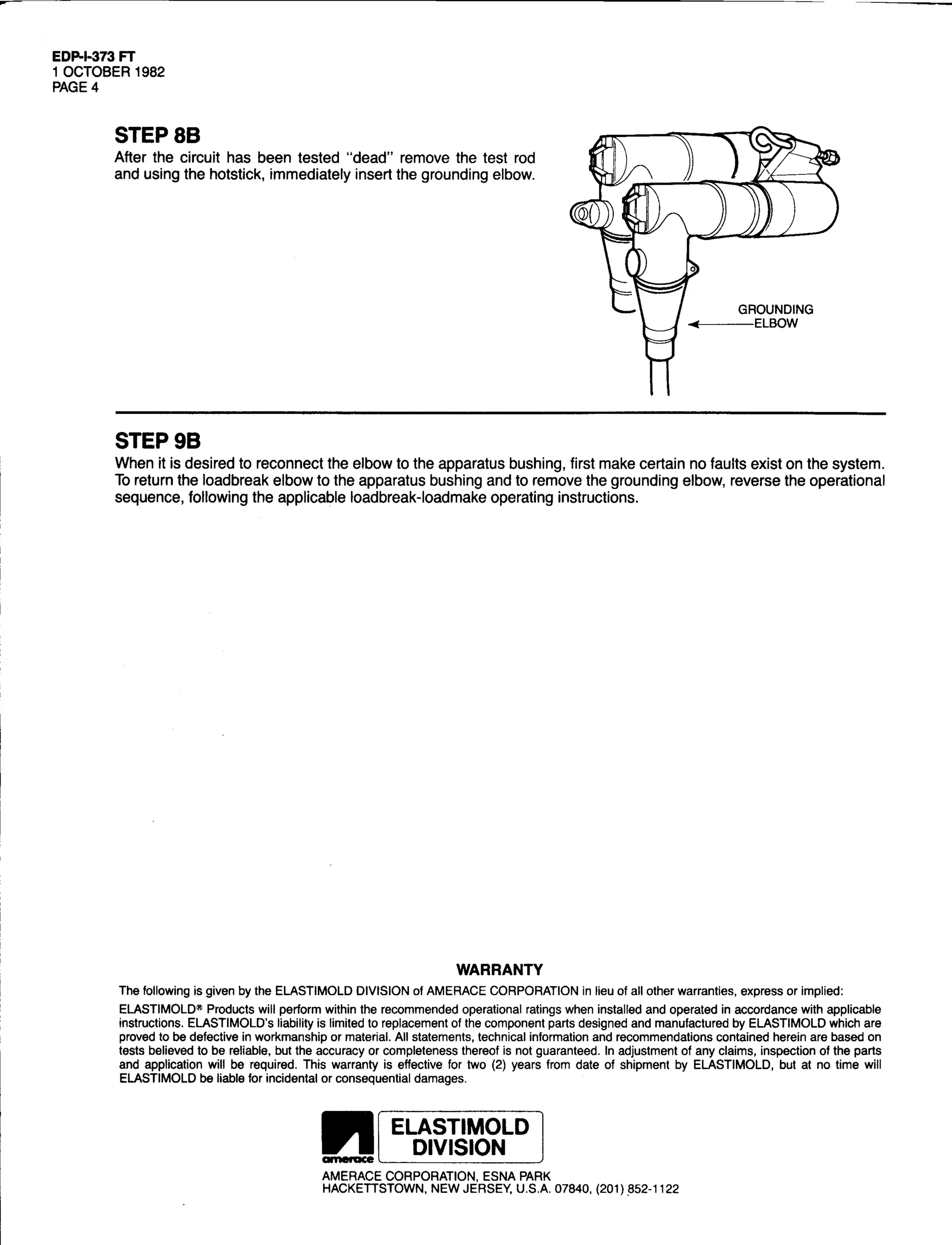
$IWHU WKH FLUFXLW KDV EHHQ WHVWHG µGHDGµ UHPRYH WKH WHVW URG
DQG XVLQJ WKH KRWVWLFN LPPHGLDWHO LQVHUW WKH JURXQGLQJ HOERZ1
*URXQGLQJ (OERZ
67(3 <%
:KHQ LW LV GHVLUHG WR UHFRQQHFW WKH HOERZ WR WKH DSSDUDWXV EXVKLQJ/ ILUVW PDNH FHUWDLQ QR IDXOWV H[LVW RQ WKH VVWHP WR UHWXUQ WKH
ORDGEUHDN HOERZ WR WKH DSSDUDWXV EXVKLQJ1 7R UHPRYH WKH JURXQGLQJ HOERZ UHYHUVH WKH RSHUDWLRQDO VHTXHQFH IROORZLQJ WKH
DSSOLFDEOH ORDGEUHDN00ORDGPDNH RSHUDWLQJ LQVWUXFWLRQV1](https://image.slidesharecdn.com/elastimold-140130102426-phpapp02/75/Elastimold-Connectors-Loadbreak-Deadbreak-Elbow-Bolted-Tee-Connectors-HV-MV-700-Series-173-2048.jpg)


![9
,60 05:9%:3
63 -DQXDU 4<<5
3DJH 4 RI 5
,QVWDOODWLRQ ,QVWUXFWLRQV
5:9%:3
&217(176= %XVKLQJ :HOO 3OXJ/ /XEULFDQW/ ,QVWDOODWLRQ ,QVWUXFWLRQV
7KH 5:9%:3 LV GHVLJQHG IRU LQVXODWLQJ DQG ZDWHUVHDOLQJ DQ (/$67,02/' 533$ EXVKLQJ ZHOO LQWHUIDFH 48N9 FODVV +;16N9 SKDVH0 0
WR0 0JURXQG24717N9 SKDVH0 0WR0 0SKDVH, RU 58N9 FODVV +4815N9 SKDVH0 0WR0 0JURXQG25916 SKDVH0 0WR0 0SKDVH,1
'$1*(5
7KLV SURGXFW VKRXOG EH LQVWDOOHG RQO E FRPSHWHQW SHUVRQ0
QHO WUDLQHG LQ JRRG VDIHW SUDFWLFHV LQYROYLQJ KLJK YROWDJH
HOHFWULFDO HTXLSPHQW1 7KHVH LQVWUXFWLRQV DUH QRW LQWHQGHG
'R QRW WRXFK RU PRYH HQHUJL]HG SURGXFWV E KDQG1
DV D VXEVWLWXWH IRU DGHTXDWH WUDLQLQJ RU H[SHULHQFH LQ VXFK
VDIHW SUDFWLFHV1
([FHVV GLVWRUWLRQ RI WKH DVVHPEOHG SURGXFW PD UHVXOW LQ LWV
7KHVH LQVWUXFWLRQV GR QRW DWWHPSW WR SURYLGH IRU HYHU SRV0
IDLOXUH1
VLEOH FRQWLQJHQF1
,QVSHFW SDUWV IRU GDPDJH/ UDWLQJ DQG FRPSDWLELOLW ZLWK PDW0
)DLOXUH WR IROORZ WKHVH LQVWUXFWLRQV FRXOG UHVXOW LQ GDPDJH
WR WKH SURGXFW DQG VHULRXV RU IDWDO LQMXU1
LQJ SDUWV1
)25 025( ,1)250$7,21 21 3$576/ ,167$//$7,21 5$7,1*6 $1' &203$7,%,/,7</ &$// 7+( 1($5(67 (/$67,02/' 2)0
),&(1
$OO DSSDUDWXV PXVW EH GH0 0HQHUJL]HG GXULQJ LQVWDOODWLRQ RU
UHPRYDO RI SDUW+V,1
,03257$17
41 &KHFN FRQWHQWV RI SDFNDJH WR LQVXUH WKH DUH FRPSOHWH
DQG XQGDPDJHG1
51 &KHFN DOO FRPSRQHQWV WR LQVXUH SURSHU ILW ZLWK FDEOH
DQG2RU PDWLQJ SURGXFWV1
61 5HDG HQWLUH LQVWDOODWLRQ LQVWUXFWLRQV EHIRUH VWDUWLQJ1
71 +DYH DOO UHTXLUHG WRROV DW KDQG DQG PDLQWDLQ FOHDQOL0 0
QHVV WKURXJKRXW WKH SURFHGXUH1
67(3 4 *5281',1*
6HFXUHO FRQQHFW HOHFWURVWDWLF JURXQGLQJ ZLUH +1R147 &RSSHU
RU HTXLYDOHQW, WR WKH JURXQGLQJ HH RI WKH EXVKLQJ ZHOO SOXJ1
*URXQGLQJ :LUH
+1R1 47 RU (TXLYDOHQW,
67(3 5 ,167$//$7,21
/XEULFDWH H[WHUQDO PDWLQJ VXUIDFH RI EXVKLQJ ZHOO SOXJ ZLWK VLOL0
FRQH OXEULFDQW SURYLGHG1 '2 127 68%67,787(1 .HHS PDWLQJ
VXUIDFHV IUHH RI GLUW DQG JULPH1
/XEULFDWH](https://image.slidesharecdn.com/elastimold-140130102426-phpapp02/75/Elastimold-Connectors-Loadbreak-Deadbreak-Elbow-Bolted-Tee-Connectors-HV-MV-700-Series-209-2048.jpg)


![9
,60 0497-5/-6
-DQXDU 4<<;
3DJH 4 RI 5
,QVWDOODWLRQ ,QVWUXFWLRQV
497-52497-6
7ZR00 DQG 7KUHH003RLQW /RDGEUHDN -XQFWLRQV
&RQWHQWV=
/RDGEUHDN -XQFWLRQ DVVHPEOHG ZLWK EDFNSODWH/ /HIW PRXQWLQJ EUDFNHW ZLWK QHFHVVDU PRXQWLQJ KDUGZDUH/
5LJKW PRXQWLQJ EUDFNHW ZLWK QHFHVVDU PRXQWLQJ KDUGZDUH/ 6LOLFRQH OXEULFDQW1
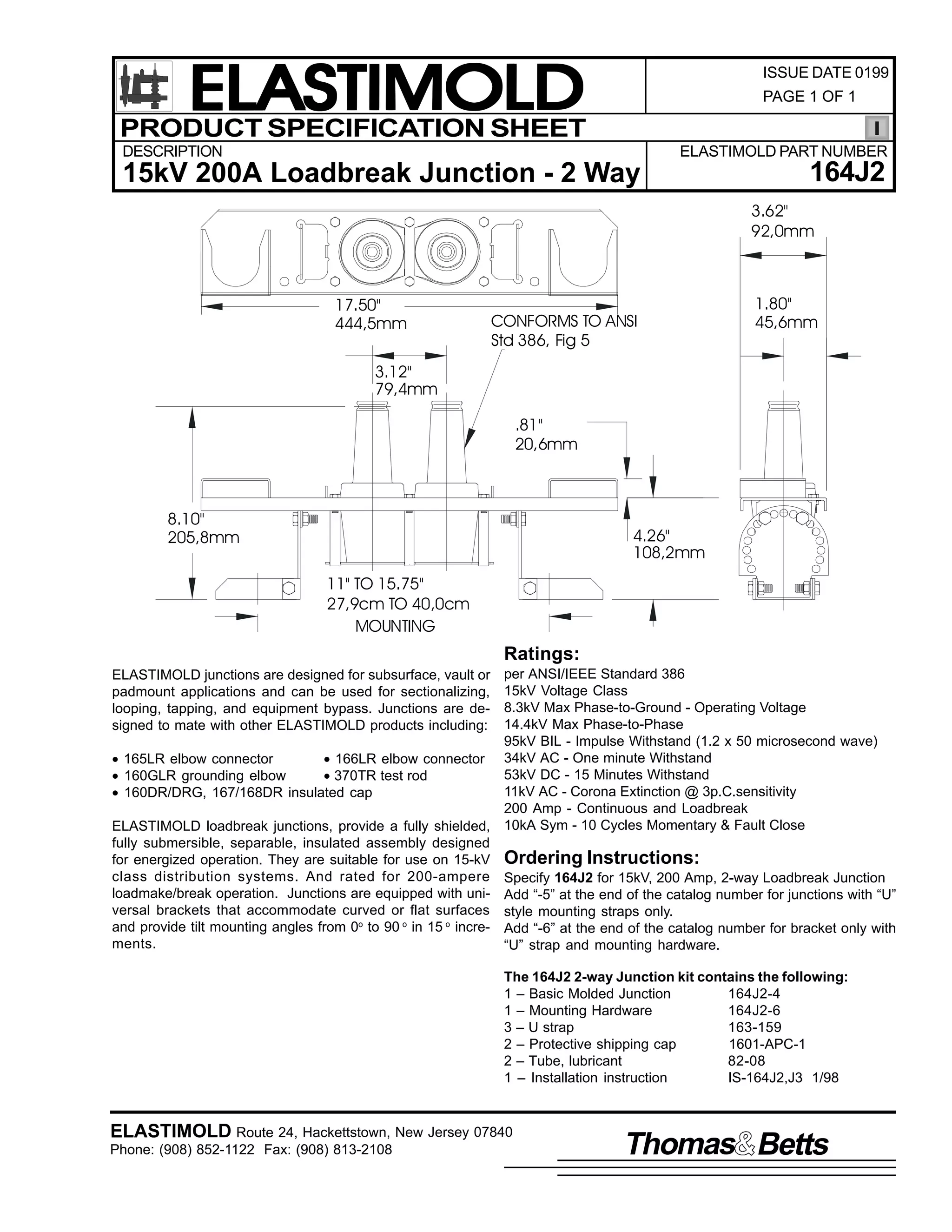
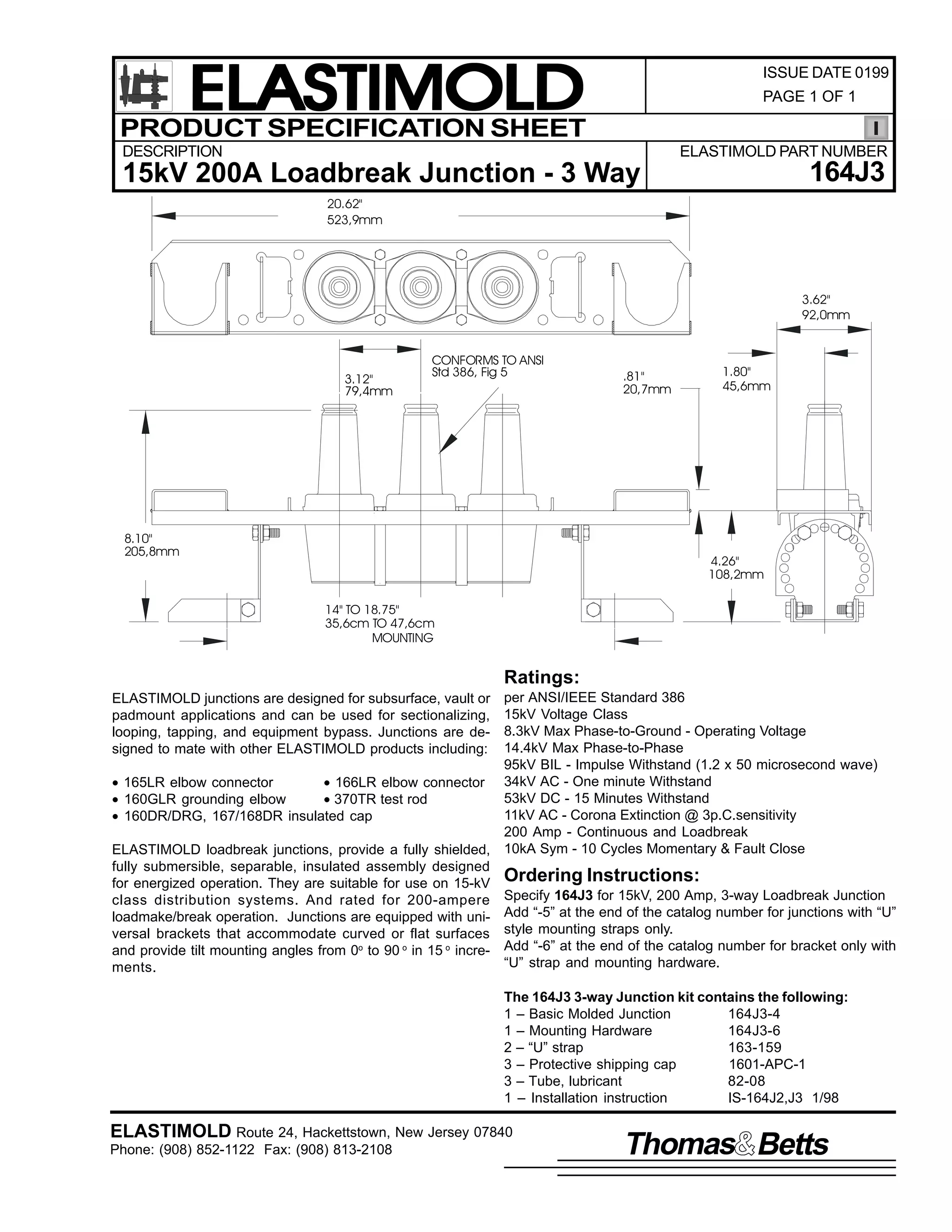
7KH WZR00 DQG WKUHH00ZD ORDGEUHDN MXQFWLRQV DUH GHVLJQHG WR LQWHUIDFH ZLWK (/$67,02/' 48N9 FODVV +;16N9
SKDVH00WR00JURXQG DQG 4717N9 SKDVH00WR00SKDVH, ORDGEUHDN FRQQHFWRUV IRU WKH SXUSRVH RI VHFWLRQDOL]LQJ/ ORRSLQJ/ WDSSLQJ RU IRU
DSSDUDWXV FKDQJH RXW1
7KH ORDGEUHDN MXQFWLRQ EUDFNHWV DUH GHVLJQHG IRU XQLYHUVDO PRXQWLQJ RQ ERWK IODW DQG FXUYHG VXUIDFHV1 7KH PRXQWLQJ DQJOH RI
WKH MXQFWLRQ LV DGMXVWDEOH IURP 3E WKUX <3EDERYH RU EHORZ WKH KRUL]RQWDO LQ 48E LQFUHPHQWV1
7KHVH MXQFWLRQV DUH DOVR DYDLODEOH ZLWKRXW WKH EDFNSODWH DQG PRXQWLQJ EUDFNHWV1 ,Q WKHVH FDVHV/ RQO 800VWUDSV DUH IXUQLVKHG
ZLWK WKH MXQFWLRQ DQG WKH XVHU PXVW PRXQW WKH MXQFWLRQV WR D IODW PHWDO VXUIDFH1
'$1*(5
$OO DSSDUDWXV PXVW EH GH00HQHUJL]HG GXULQJ LQVWDOODWLRQ
RU UHPRYDO RI SDUW+V,1
'R QRW WRXFK RU PRYH HQHUJL]HG SURGXFWV E KDQG1
([FHVV GLVWRUWLRQ RI WKH DVVHPEOHG SURGXFW PD UHVXOW
LQ LWV IDLOXUH1
,QVSHFW SDUWV IRU GDPDJH/ UDWLQJ DQG FRPSDWLELOLW ZLWK
PDWLQJ SDUWV1
7KLV SURGXFW VKRXOG EH LQVWDOOHG RQO E FRPSHWHQW
SHUVRQQHO WUDLQHG LQ JRRG VDIHW SUDFWLFHV LQYROYLQJ
KLJK YROWDJH HOHFWULFDO HTXLSPHQW1 7KHVH LQVWUXFWLRQV
DUH QRW LQWHQGHG DV D VXEVWLWXWH IRU DGHTXDWH WUDLQLQJ RU
H[SHULHQFH LQ VXFK VDIHW SUDFWLFHV1
7KHVH LQVWUXFWLRQV GR QRW DWWHPSW WR SURYLGH IRU HYHU
SRVVLEOH FRQWLQJHQF1
)DLOXUH WR IROORZ WKHVH LQVWUXFWLRQV ZLOO UHVXOW LQ
GDPDJH WR WKH SURGXFW DQG VHULRXV RU IDWDO LQMXU1
7KHVH SURGXFWV DUH VXSSOLHG ZLWK D SURWHFWLYH VKLSSLQJ
FRYHUV1 5HPRYH WKHVH VKLSSLQJ FRYHUV DQG UHSODFH
ZLWK WKH DSSURSULDWH +9 LQVXODWHG FDS RU FRQQHFWRU
EHIRUH VXEPHUJLQJ RU HQHUJL]LQJ WKH FLUFXLW1
)25 025( ,1)250$7,21 21 3$576/ ,167$//$7,21/ 5$7,1*6 $1' &203$7,%,/,7</ &$// 7+( 1($5(67 (/$67,02/' 2)),&(1
,03257$17
41 &KHFN FRQWHQWV RI SDFNDJH WR LQVXUH WKH DUH FRPSOHWH
DQG XQGDPDJHG1
%DFN 3ODWH
0RXQWLQJ $QJOH
51 &KHFN DOO FRPSRQHQWV WR LQVXUH SURSHU ILW ZLWK FDEOH
DQG2RU PDWLQJ SURGXFWV1
61 5HDG HQWLUH LQVWDOODWLRQ LQVWUXFWLRQV EHIRUH VWDUWLQJ1
71 +DYH DOO UHTXLUHG WRROV DW KDQG DQG PDLQWDLQ FOHDQOLQHVV
WKURXJKRXW WKH SURFHGXUH1
67(3 4
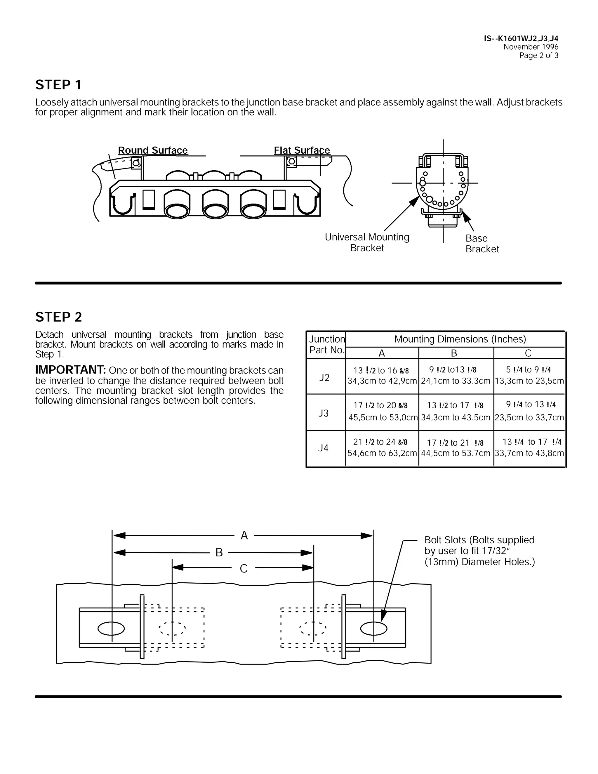
/RRVHO DWWDFK XQLYHUVDO PRXQWLQJ EUDFNHWV WR WKH
MXQFWLRQ EDFNSODWH DQG SODFH DVVHPEO DJDLQVW WKH ZDOO1
$GMXVW EUDFNHWV IRU SURSHU DOLJQPHQW DQG PDUN WKHLU
ORFDWLRQ RQ WKH ZDOO1
,60 0497-5/-6
-DQXDU 4<<;
3ULQWHG LQ WKH 8161$1
8QLYHUVDO 0RXQWLQJ
%UDFNHW
+RUL]RQWDO
5RXQG 6XUIDFH
(VQD 3DUN 'ULYH/ +DFNHWWVWRZQ/ 1HZ -HUVH 3:;73 86$
+<3;,;850 04455 )$;= +<3;,;460 0547:
$ 8QLW RI 7KRPDV ) %HWWV &RUSRUDWLRQ
)ODW 6XUIDFH](https://image.slidesharecdn.com/elastimold-140130102426-phpapp02/75/Elastimold-Connectors-Loadbreak-Deadbreak-Elbow-Bolted-Tee-Connectors-HV-MV-700-Series-227-2048.jpg)
![,60 0497-5/-6
-DQXDU 4<<;
3DJH 5 RI 5
67(3 5
'HWDFK XQLYHUVDO PRXQWLQJ EUDFNHWV IURP MXQFWLRQ EDFN SODWH1 0RXQW EUDFNHWV RQ ZDOO DFFRUGLQJ WR PDUNV PDGH LQ 6WHS 41
2QH RU ERWK RI WKH PRXQWLQJ EUDFNHWV FDQ EH LQYHUWHG WR FKDQJH WKH GLVWDQFH UHTXLUHG EHWZHHQ EROW FHQWHUV1 7KH PRXQWLQJ
EUDFNHW VORW OHQJWK SURYLGHV WKH IROORZLQJ GLPHQVLRQDO UDQJHV EHWZHHQ EROW FHQWHUV1
$
-XQFWLRQ
3DUW 1R1
%
&
0RXQWLQJ 'LPHQVLRQV +,QFKHV2FP,
$
&
%
497-5
44 WR 48 ñ2á
5:/<FP WR 73/3FP
9 î2# WR 44 ñ2á
4:/8FP WR 5</;FP
6 WR : ñ2á
:/9FP WR 4</:FP
497-6
47 WR 4; ñ2á
68/9FP WR 7:/9FP
43 WR 47 î2#
58/7FP WR 6:/;FP
9 ó2# WR 43 ñ2á
48/9FP WR 5:/6FP
%ROW 6ORWV +%ROWV VXSSOLHG E XVHU WR
ILW 4:265l +46/8PP, 'LD1 +ROHV1,
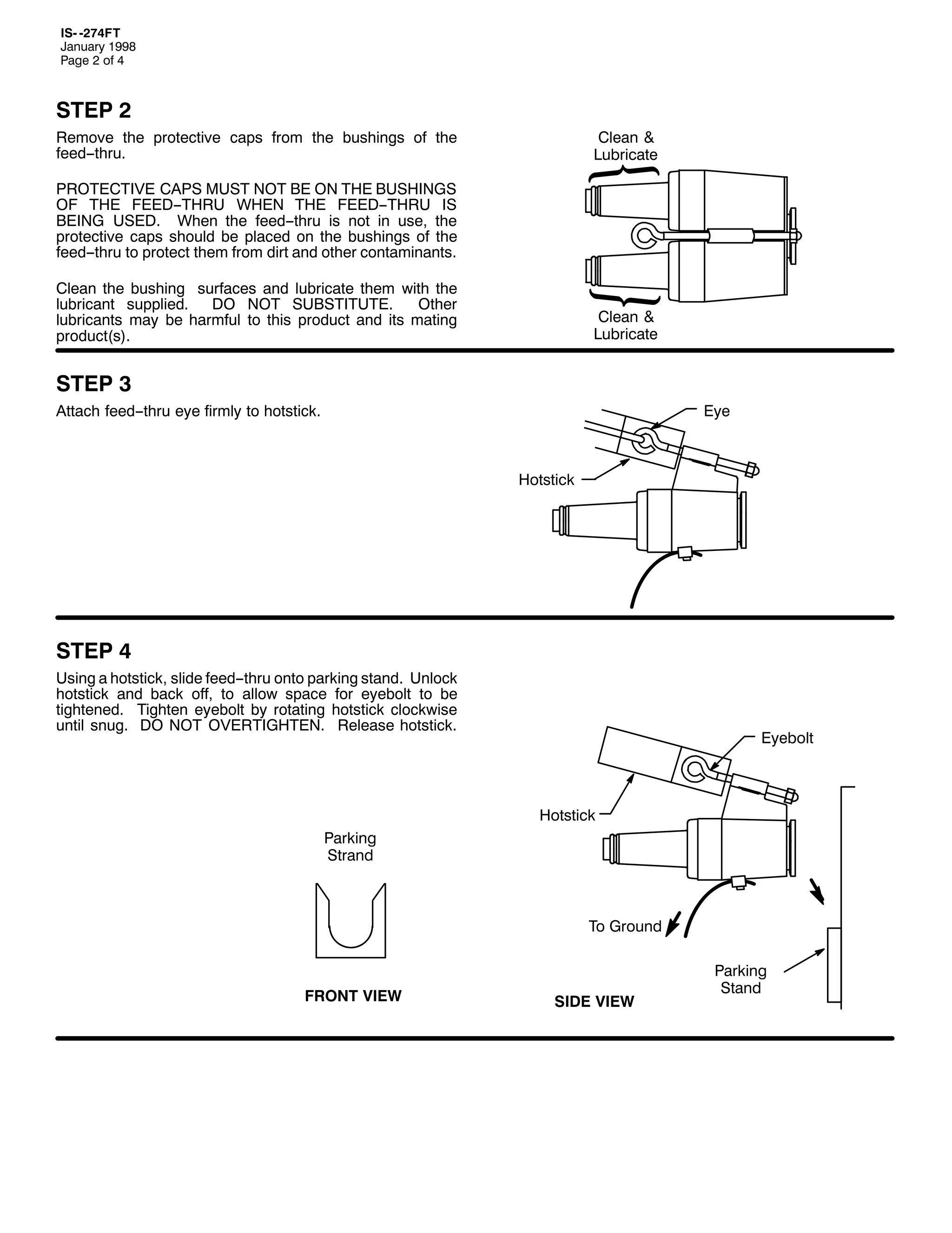
67(3 6
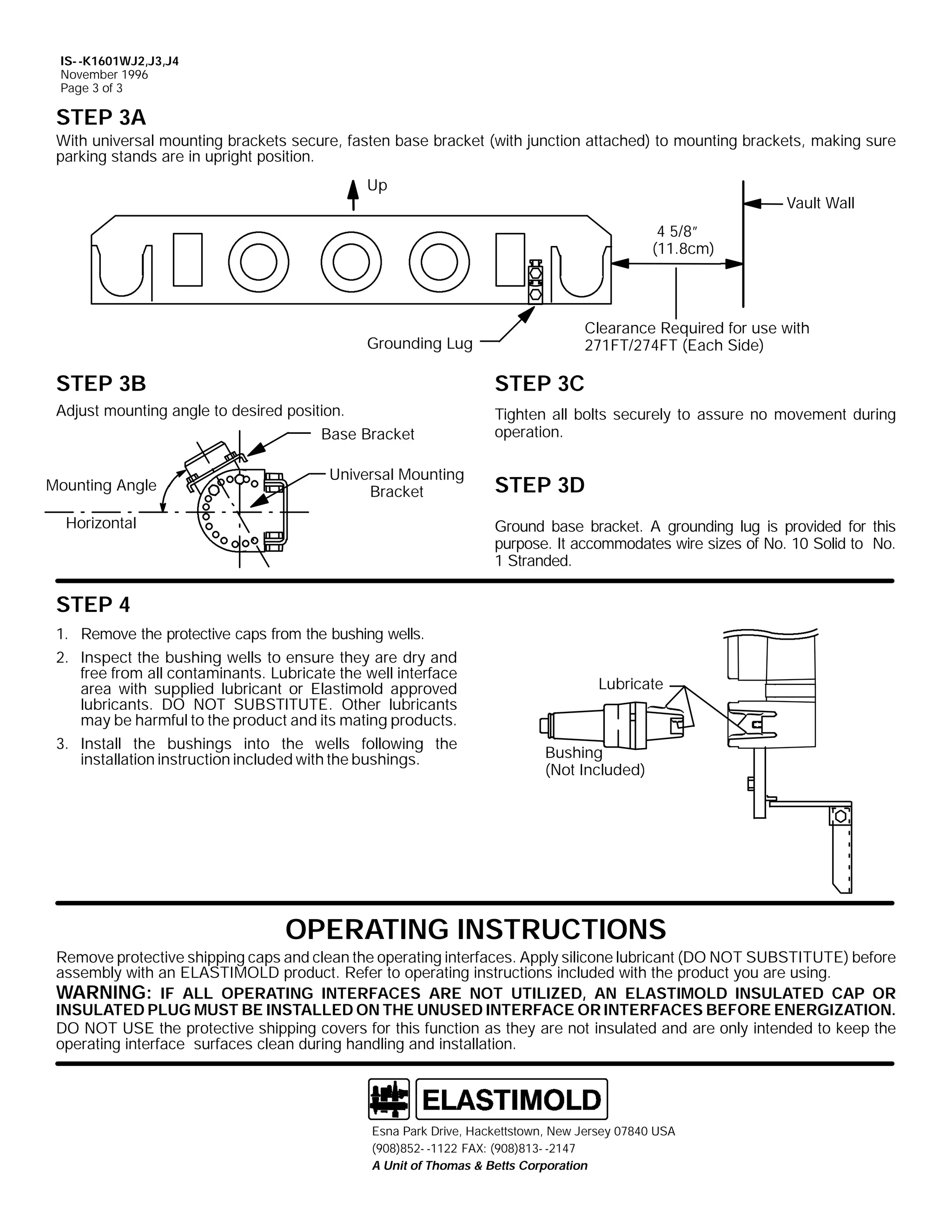
:LWK XQLYHUVDO PRXQWLQJ EUDFNHWV VHFXUH/ IDVWHQ EDFN SODWH +ZLWK MXQFWLRQ DWWDFKHG, WR PRXQWLQJ EUDFNHWV/ PDNLQJ VXUH SDUNLQJ
VWDQGV DUH LQ XSULJKW SRVLWLRQ1
8S
9DXOW :DOO
4 425l
+6/;FP,
*URXQGLQJ /XJ
&OHDUDQFH 5HTXLUHG IRU XVH
ZLWK 497)75 +(DFK 6LGH,
67(3 7
$GMXVW PRXQWLQJ DQJOH WR GHVLUHG SRVLWLRQ1
67(3 8
7LJKWHQ DOO EROWV VHFXUHO WR DVVXUH QR PRYHPHQW GXULQJ RSHUDWLRQ1
67(3 9
7KH EDFNSODWH DQG VXSSRUWHG MXQFWLRQ·V EODFN FRQGXFWLYH MDFNHW PXVW EH JURXQGHG1 $ JURXQGLQJ OXJ LV SURYLGHG RQ WKH
EDFNSODWH IRU WKLV SXUSRVH1 ,W DFFRPPRGDWHV ZLUH VL]HV RI 1R1 5 VROLG WR 413 VWUDQGHG1 ,Q WKH FDVH ZKHUH WKH MXQFWLRQ LV PRXQWHG
ZLWKRXW WKH EDFNSODWH/ WKH MXQFWLRQ EODFN FRQGXFWLYH MDFNHW PXVW EH JURXQGHG E RWKHU PHDQV1
23(5$7,1* ,16758&7,216
5HPRYH SURWHFWLYH FDSV DQG FOHDQ EXVKLQJV1 $SSO VLOLFRQH OXEULFDQW +'2 127 68%67,787(, EHIRUH DVVHPEO ZLWK DQ
(/$67,02/' ORDGEUHDN FRQQHFWRU1 5HIHU WR ,600498/52499/5/ EHIRUH RSHUDWLQJ MXQFWLRQV ZLWK ORDGEUHDN HOERZ FRQQHFWRUV1
:$51,1*= ,) $// %86+,1*6 $5( 127 87,/,=('/ $1 (/$67,02/' ,168/$7(' &$3 0867 %(
,167$//(' 21 7+( 8186(' %86+,1*6 %()25( (1(5*,=$7,211
'2 127 86( WKH SURWHFWLYH VKLSSLQJ FRYHUV IRU WKLV IXQFWLRQ DV WKH DUH QRW LQVXODWHG DQG DUH RQO LQWHQGHG WR NHHS WKH
EXVKLQJ VXUIDFHV FOHDQ GXULQJ KDQGOLQJ DQG LQVWDOODWLRQ1
(VQD 3DUN 'ULYH/ +DFNHWWVWRZQ/ 1HZ -HUVH 3:;73 86$
+<3;,;850 04455 )$;= +<3;,;460 0547:
$ 8QLW RI 7KRPDV ) %HWWV &RUSRUDWLRQ](https://image.slidesharecdn.com/elastimold-140130102426-phpapp02/75/Elastimold-Connectors-Loadbreak-Deadbreak-Elbow-Bolted-Tee-Connectors-HV-MV-700-Series-228-2048.jpg)
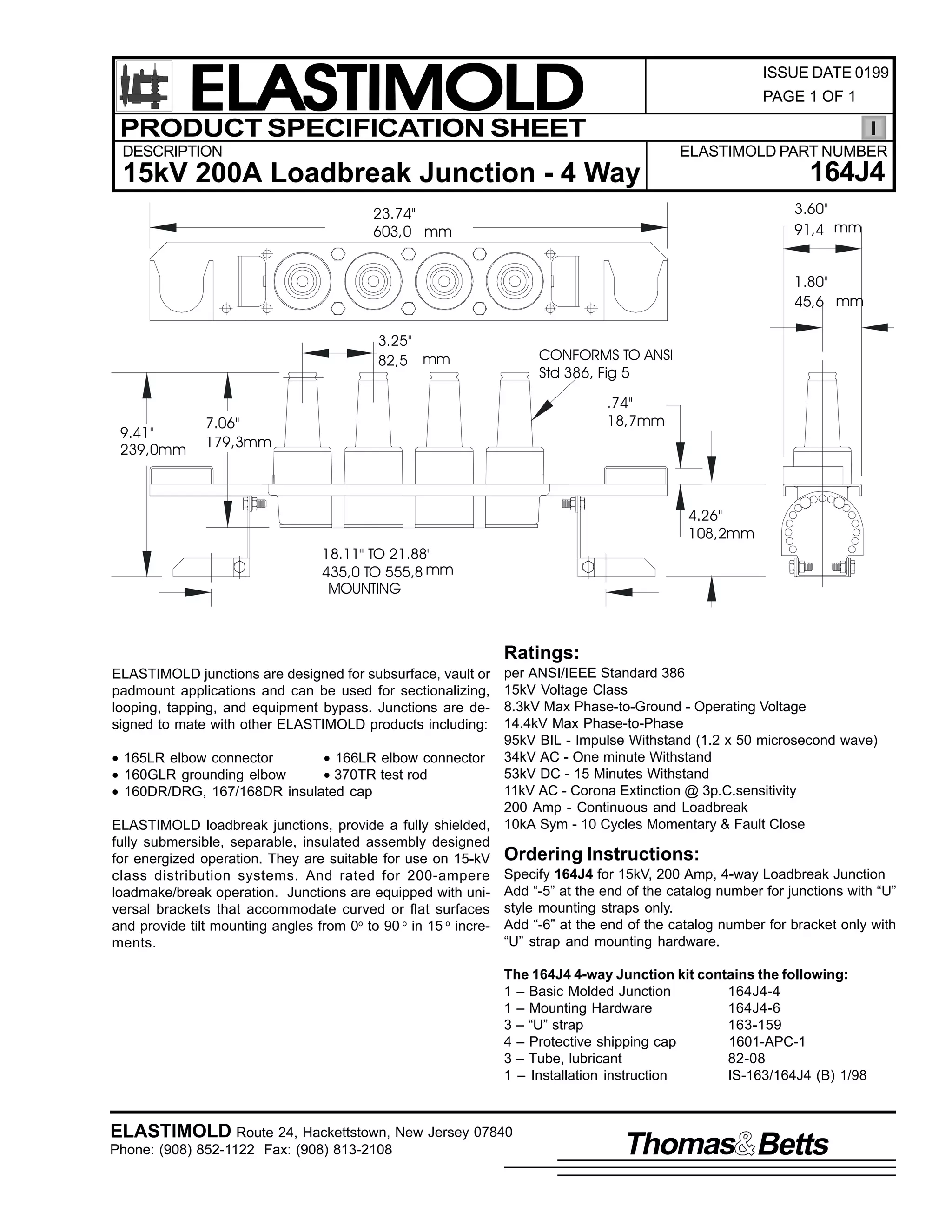
![9
,60 04962497-7+%,
-DQXDU 4<<;
3DJH 4 RI 5
,QVWDOODWLRQ ,QVWUXFWLRQV
4962497-7+%,
)RXU003RLQW /RDGEUHDN -XQFWLRQV
&RQWHQWV=
/RDGEUHDN -XQFWLRQ DVVHPEOHG ZLWK EDFNSODWH/ /HIW PRXQWLQJ EUDFNHW ZLWK QHFHVVDU PRXQWLQJ KDUGZDUH/
5LJKW PRXQWLQJ EUDFNHW ZLWK QHFHVVDU PRXQWLQJ KDUGZDUH/ 6LOLFRQH OXEULFDQW/ ,QVWDOODWLRQ ,QVWUXFWLRQV1
7KH IRXU00ZD ORDGEUHDN MXQFWLRQV DUH GHVLJQHG WR LQWHUIDFH ZLWK (/$67,02/' 48N9 FODVV +;16N9 SKDVH00WR00JURXQG DQG
4717N9 SKDVH00WR00SKDVH, ORDGEUHDN FRQQHFWRUV IRU WKH SXUSRVH RI VHFWLRQDOL]LQJ/ ORRSLQJ/ WDSSLQJ RU IRU DSSDUDWXV FKDQJH RXW1
7KH ORDGEUHDN MXQFWLRQ EUDFNHWV DUH GHVLJQHG IRU XQLYHUVDO PRXQWLQJ RQ ERWK IODW DQG FXUYHG VXUIDFHV1 7KH PRXQWLQJ DQJOH RI
WKH MXQFWLRQ LV DGMXVWDEOH IURP 3E WKUX <3E DERYH RU EHORZ WKH KRUL]RQWDO LQ 48E LQFUHPHQWV1
7KHVH MXQFWLRQV DUH DOVR DYDLODEOH ZLWKRXW WKH EDFNSODWH DQG PRXQWLQJ EUDFNHWV1 ,Q WKHVH FDVHV/ RQO 800VWUDSV DUH IXUQLVKHG
ZLWK WKH MXQFWLRQ DQG WKH XVHU PXVW PRXQW WKH MXQFWLRQV WR D IODW PHWDO VXUIDFH1
'$1*(5
$OO DSSDUDWXV PXVW EH GH00HQHUJL]HG GXULQJ LQVWDOODWLRQ
RU UHPRYDO RI SDUW+V,1
'R QRW WRXFK RU PRYH HQHUJL]HG SURGXFWV E KDQG1
([FHVV GLVWRUWLRQ RI WKH DVVHPEOHG SURGXFW PD UHVXOW
LQ LWV IDLOXUH1
,QVSHFW SDUWV IRU GDPDJH/ UDWLQJ DQG FRPSDWLELOLW ZLWK
PDWLQJ SDUWV1
7KLV SURGXFW VKRXOG EH LQVWDOOHG RQO E FRPSHWHQW
SHUVRQQHO WUDLQHG LQ JRRG VDIHW SUDFWLFHV LQYROYLQJ
KLJK YROWDJH HOHFWULFDO HTXLSPHQW1 7KHVH LQVWUXFWLRQV
DUH QRW LQWHQGHG DV D VXEVWLWXWH IRU DGHTXDWH WUDLQLQJ RU
H[SHULHQFH LQ VXFK VDIHW SUDFWLFHV1
7KHVH LQVWUXFWLRQV GR QRW DWWHPSW WR SURYLGH IRU HYHU
SRVVLEOH FRQWLQJHQF1
)DLOXUH WR IROORZ WKHVH LQVWUXFWLRQV ZLOO UHVXOW LQ
GDPDJH WR WKH SURGXFW DQG VHULRXV RU IDWDO LQMXU1
7KHVH SURGXFWV DUH VXSSOLHG ZLWK D SURWHFWLYH VKLSSLQJ
FRYHUV1 5HPRYH WKHVH VKLSSLQJ FRYHUV DQG UHSODFH
ZLWK WKH DSSURSULDWH +9 LQVXODWHG FDS RU FRQQHFWRU
EHIRUH VXEPHUJLQJ RU HQHUJL]LQJ WKH FLUFXLW1
)25 025( ,1)250$7,21 21 3$576/ ,167$//$7,21/ 5$7,1*6 $1' &203$7,%,/,7</ &$// 7+( 1($5(67 (/$67,02/' 2)),&(1
,03257$17
41 &KHFN FRQWHQWV RI SDFNDJH WR LQVXUH WKH DUH FRPSOHWH
DQG XQGDPDJHG1
%DFN 3ODWH
0RXQWLQJ $QJOH
51 &KHFN DOO FRPSRQHQWV WR LQVXUH SURSHU ILW ZLWK FDEOH
DQG2RU PDWLQJ SURGXFWV1
61 5HDG HQWLUH LQVWDOODWLRQ LQVWUXFWLRQV EHIRUH VWDUWLQJ1
71 +DYH DOO UHTXLUHG WRROV DW KDQG DQG PDLQWDLQ FOHDQOLQHVV
WKURXJKRXW WKH SURFHGXUH1
67(3 4
/RRVHO DWWDFK XQLYHUVDO PRXQWLQJ EUDFNHWV WR WKH MXQFWLRQ
EDFNSODWH DQG SODFH DVVHPEO DJDLQVW WKH ZDOO1 $GMXVW
EUDFNHWV IRU SURSHU DOLJQPHQW DQGPDUN WKHLU ORFDWLRQ RQWKH
ZDOO1
,60 04962497-7+%,
-DQXDU 4<<;
3ULQWHG LQ WKH 8161$1
8QLYHUVDO 0RXQWLQJ
%UDFNHW
+RUL]RQWDO
5RXQG 6XUIDFH
(VQD 3DUN 'ULYH/ +DFNHWWVWRZQ/ 1HZ -HUVH 3:;73 86$
+<3;,;850 04455 )$;= +<3;,;460 0547:
$ 8QLW RI 7KRPDV ) %HWWV &RUSRUDWLRQ
)ODW 6XUIDFH](https://image.slidesharecdn.com/elastimold-140130102426-phpapp02/75/Elastimold-Connectors-Loadbreak-Deadbreak-Elbow-Bolted-Tee-Connectors-HV-MV-700-Series-230-2048.jpg)
![,60 04962497-7+%,
-DQXDU 4<<;
3DJH 5 RI 5
67(3 5
'HWDFK XQLYHUVDO PRXQWLQJ EUDFNHWV IURP MXQFWLRQ EDFN SODWH1 0RXQW EUDFNHWV RQ ZDOO DFFRUGLQJ WR PDUNV PDGH LQ 6WHS 41
2QH RU ERWK RI WKH PRXQWLQJ EUDFNHWV FDQ EH LQYHUWHG WR FKDQJH WKH GLVWDQFH UHTXLUHG EHWZHHQ EROW FHQWHUV1 7KH PRXQWLQJ
EUDFNHW VORW OHQJWK SURYLGHV WKH IROORZLQJ GLPHQVLRQDO UDQJHV EHWZHHQ EROW FHQWHUV1
$
-XQFWLRQ
3DUW 1R1
%
&
4962497-7+%,
0RXQWLQJ 'LPHQVLRQV +,QFKHV2FP,
$
%
&
4: ó2# WR 54 î2# 46 ó2# WR 4: î2#
< ó2# WR 46 î2#
76/8FP WR 88/9FP 66/6FP WR 78/7FP 56/5FP WR 68/5FP
%ROW 6ORWV +%ROWV VXSSOLHG E XVHU WR
ILW 4:265l +46/8PP, 'LD1 +ROHV1,
67(3 6
:LWK XQLYHUVDO PRXQWLQJ EUDFNHWV VHFXUH/ IDVWHQ EDFN SODWH +ZLWK MXQFWLRQ DWWDFKHG, WR PRXQWLQJ EUDFNHWV/ PDNLQJ VXUH SDUNLQJ
VWDQGV DUH LQ XSULJKW SRVLWLRQ1
8S
9DXOW :DOO
4 425l
+6/;FP,
*URXQGLQJ /XJ
&OHDUDQFH 5HTXLUHG IRU XVH
ZLWK 497)75 +(DFK 6LGH,
67(3 7
$GMXVW PRXQWLQJ DQJOH WR GHVLUHG SRVLWLRQ1
67(3 8
7LJKWHQ DOO EROWV VHFXUHO WR DVVXUH QR PRYHPHQW GXULQJ RSHUDWLRQ1
67(3 9
7KH EDFNSODWH DQG VXSSRUWHG MXQFWLRQ·V EODFN FRQGXFWLYH MDFNHW PXVW EH JURXQGHG1 $ JURXQGLQJ OXJ LV SURYLGHG RQ WKH
EDFNSODWH IRU WKLV SXUSRVH1 ,W DFFRPPRGDWHV ZLUH VL]HV RI 1R1 5 VROLG WR 413 VWUDQGHG1 ,Q WKH FDVH ZKHUH WKH MXQFWLRQ LV PRXQWHG
ZLWKRXW WKH EDFNSODWH/ WKH MXQFWLRQ EODFN FRQGXFWLYH MDFNHW PXVW EH JURXQGHG E RWKHU PHDQV1
23(5$7,1* ,16758&7,216
5HPRYH SURWHFWLYH FDSV DQG FOHDQ EXVKLQJV1 $SSO VLOLFRQH OXEULFDQW +'2 127 68%67,787(, EHIRUH DVVHPEO ZLWK DQ
(/$67,02/' ORDGEUHDN FRQQHFWRU1 5HIHU WR WKH DSSURSULDWH RSHUDWLQJ LQVWUXFWLRQV SDFNDJHG ZLWK WKH FRQQHFWRU DVVHPEO
EHLQJ XVHG/ EHIRUH RSHUDWLQJ MXQFWLRQV ZLWK ORDGEUHDN HOERZ FRQQHFWRUV1
:$51,1*= ,) $// %86+,1*6 $5( 127 87,/,=('/ $1 (/$67,02/' ,168/$7(' &$3 0867 %(
,167$//(' 21 7+( 8186(' %86+,1*6 %()25( (1(5*,=$7,211
'2 127 86( WKH SURWHFWLYH VKLSSLQJ FRYHUV IRU WKLV IXQFWLRQ DV WKH DUH QRW LQVXODWHG DQG DUH RQO LQWHQGHG WR NHHS WKH
EXVKLQJ VXUIDFHV FOHDQ GXULQJ KDQGOLQJ DQG LQVWDOODWLRQ1
(VQD 3DUN 'ULYH/ +DFNHWWVWRZQ/ 1HZ -HUVH 3:;73 86$
+<3;,;850 04455 )$;= +<3;,;460 0547:
$ 8QLW RI 7KRPDV ) %HWWV &RUSRUDWLRQ](https://image.slidesharecdn.com/elastimold-140130102426-phpapp02/75/Elastimold-Connectors-Loadbreak-Deadbreak-Elbow-Bolted-Tee-Connectors-HV-MV-700-Series-231-2048.jpg)
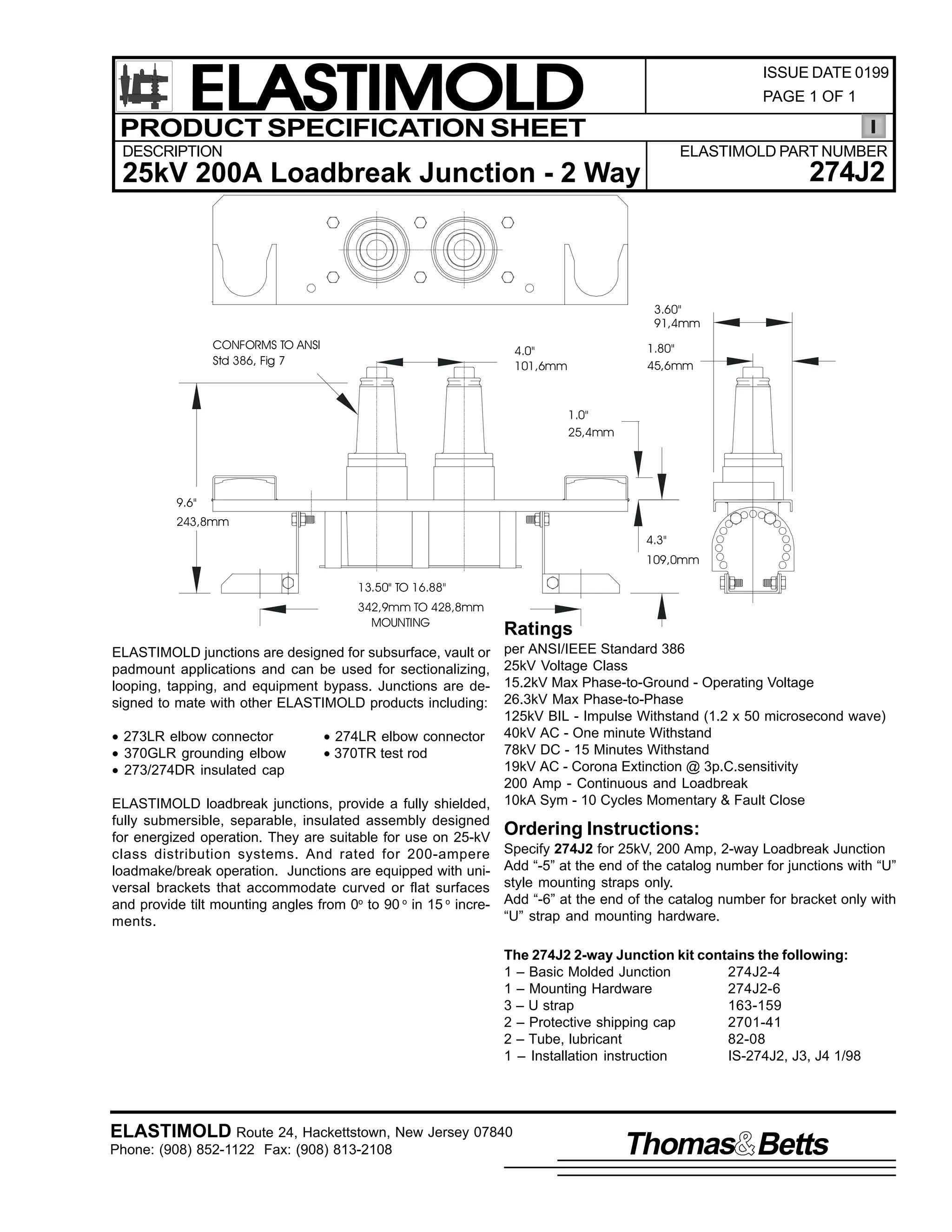
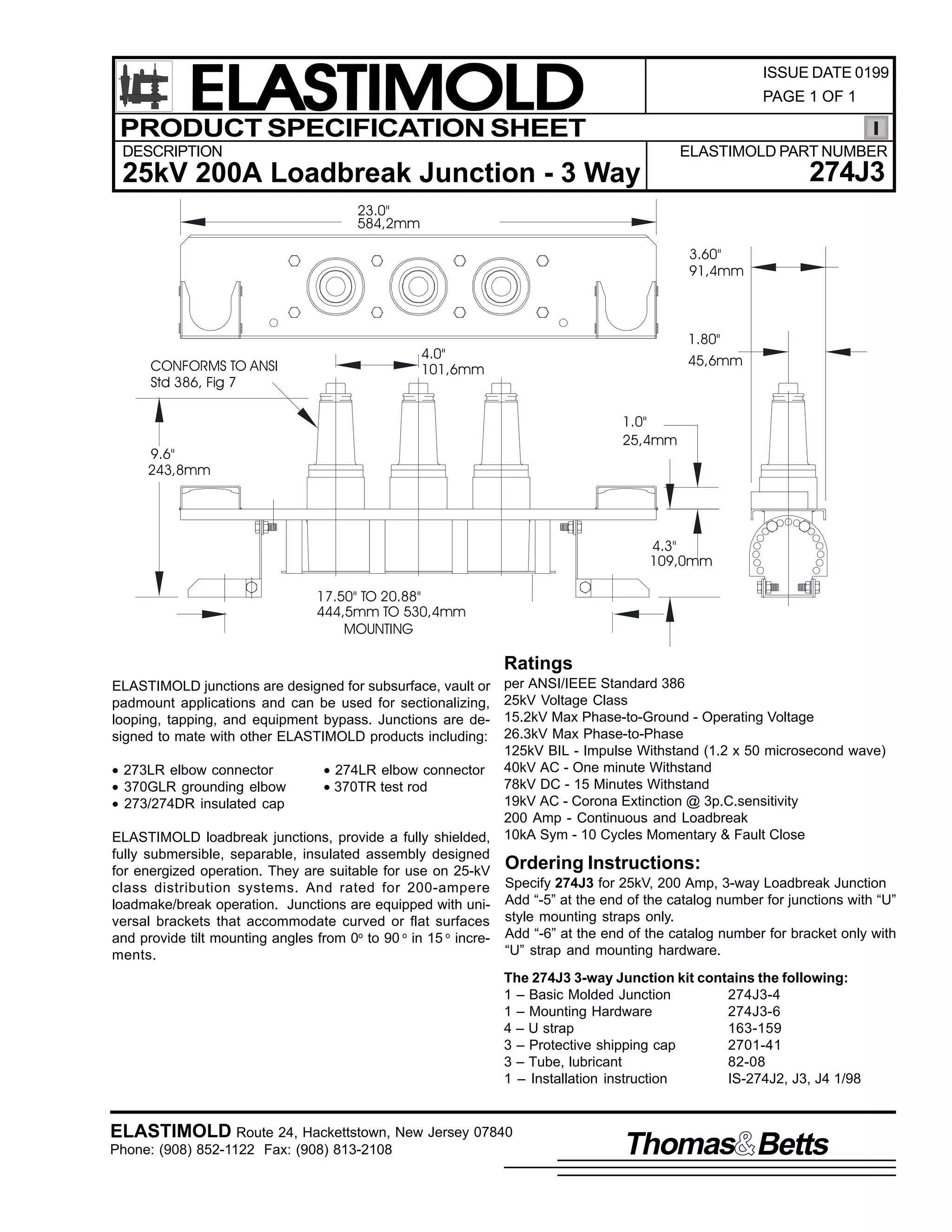
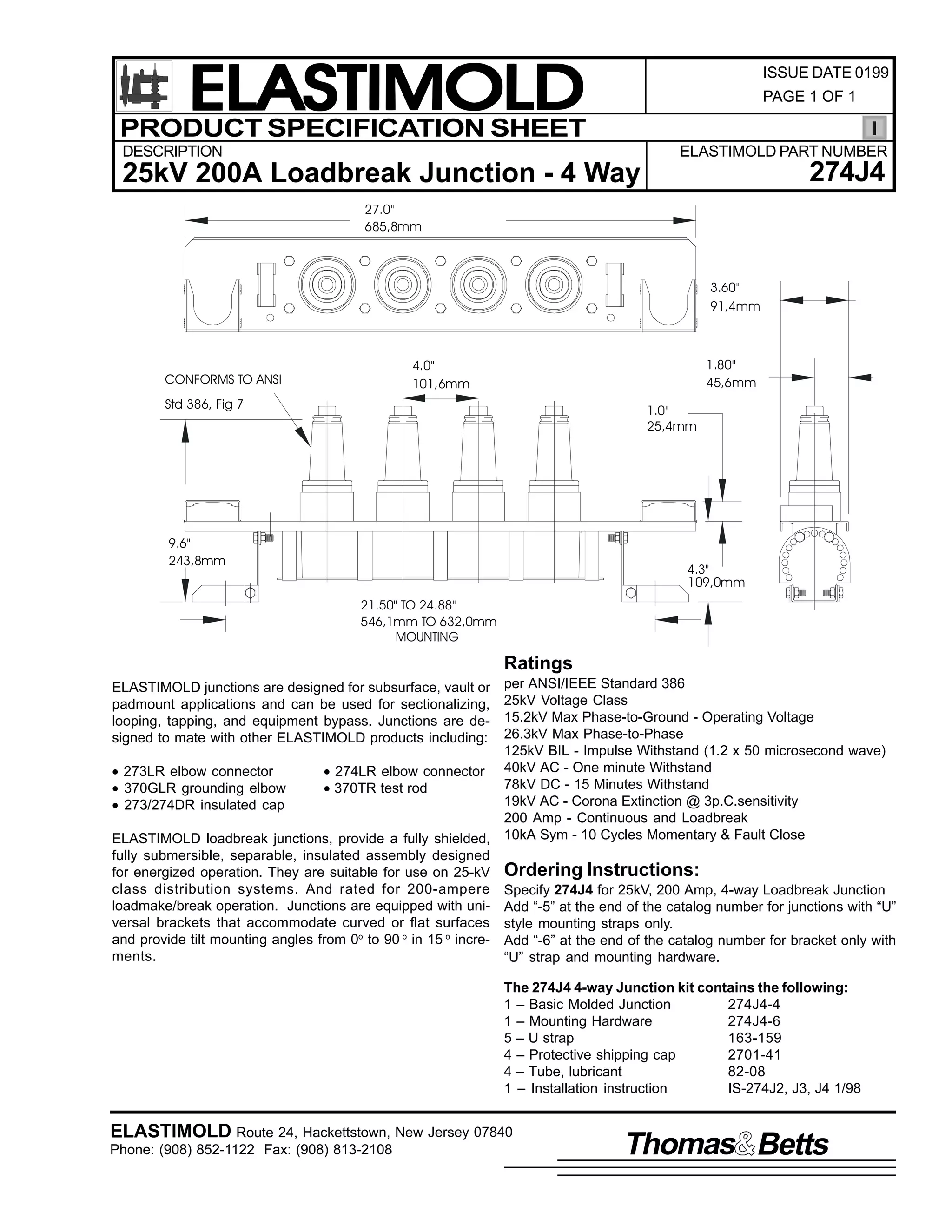
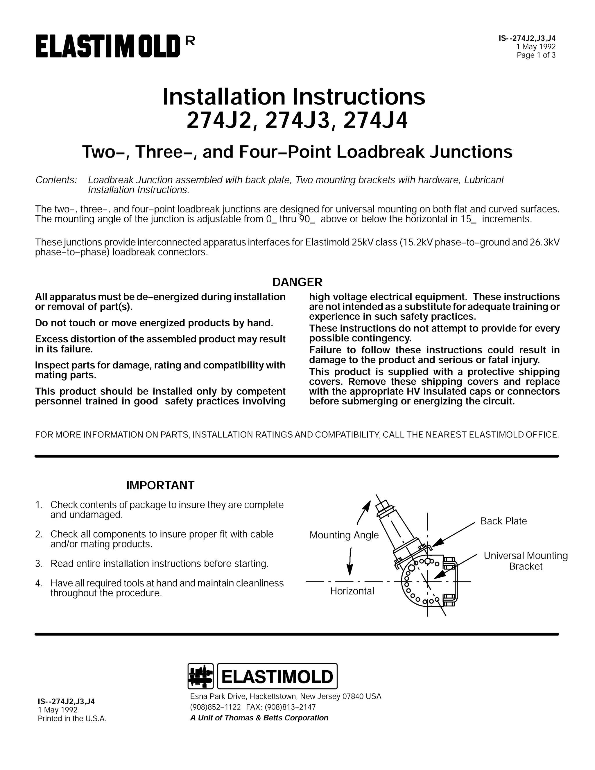
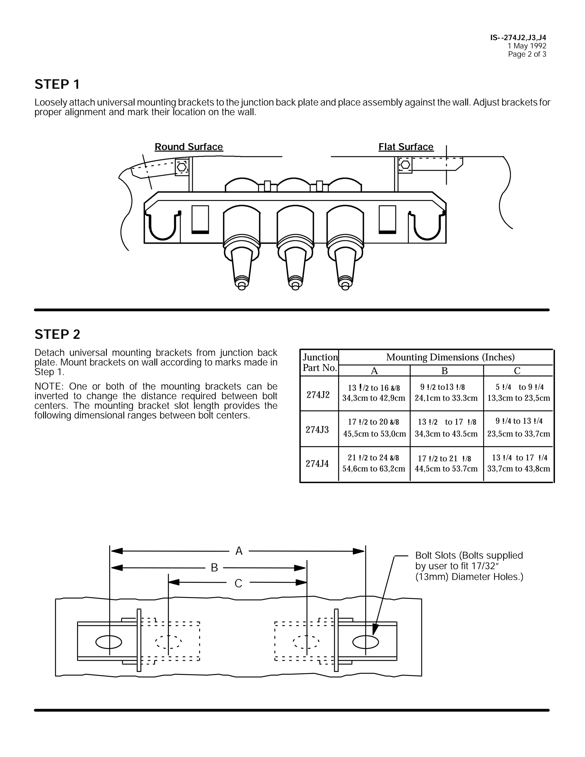
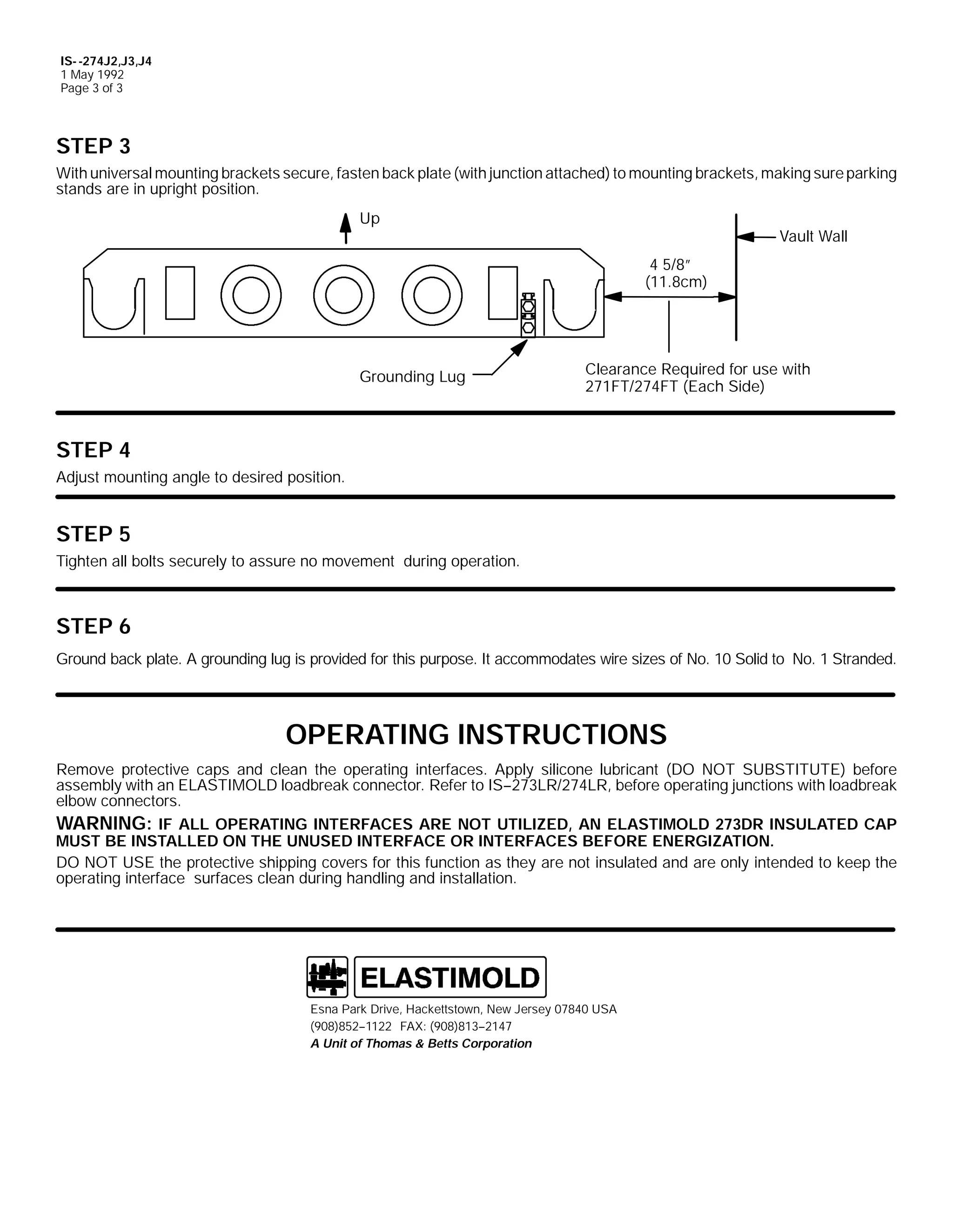
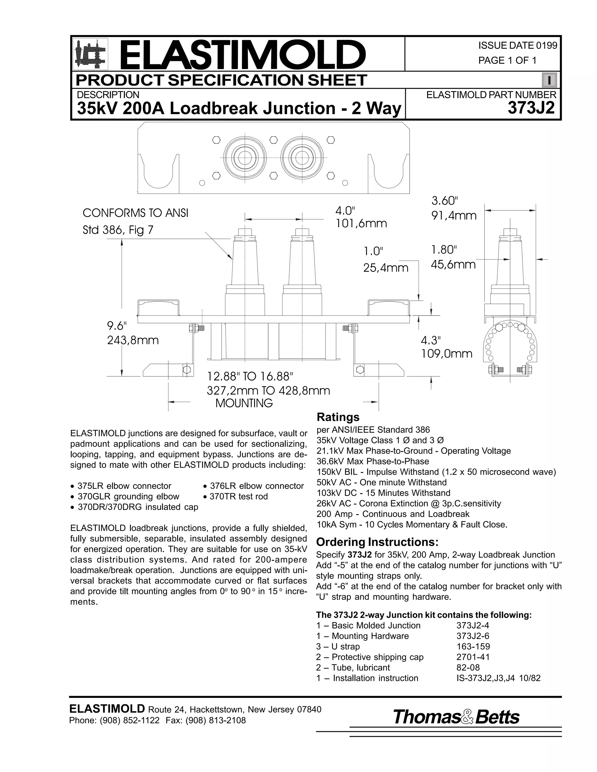
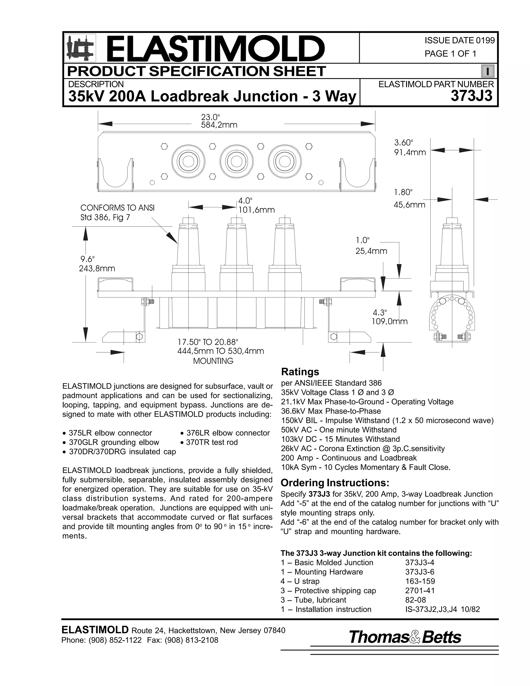
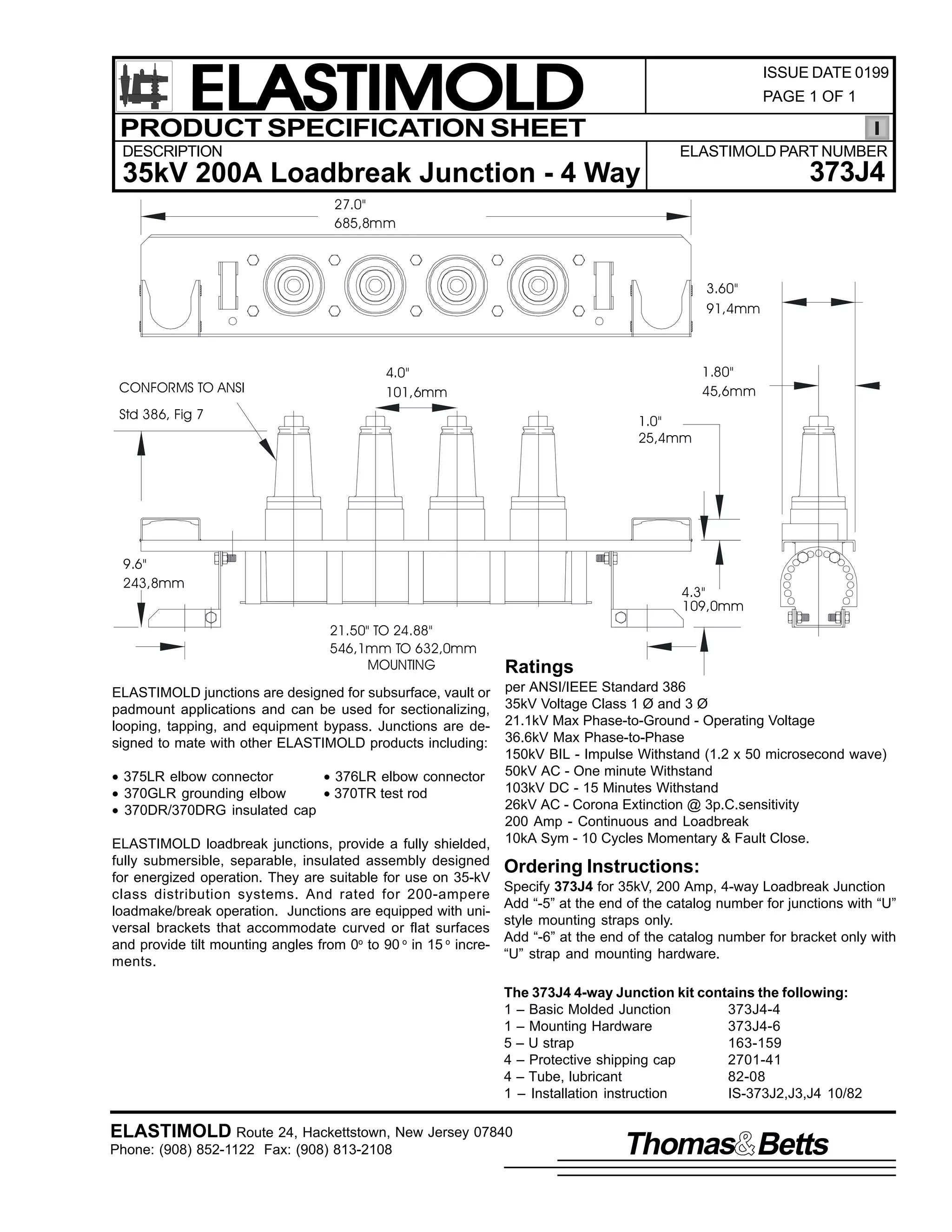
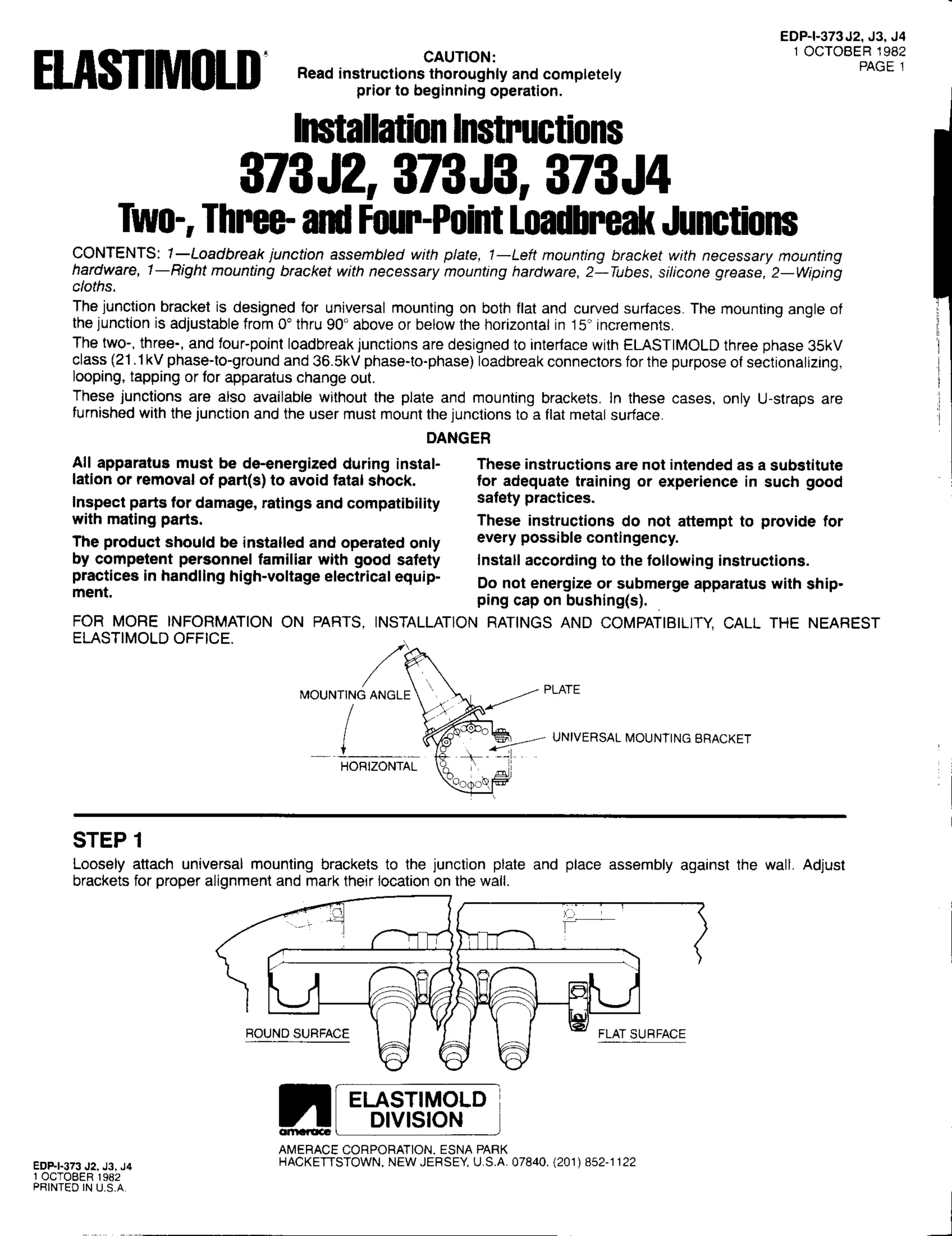
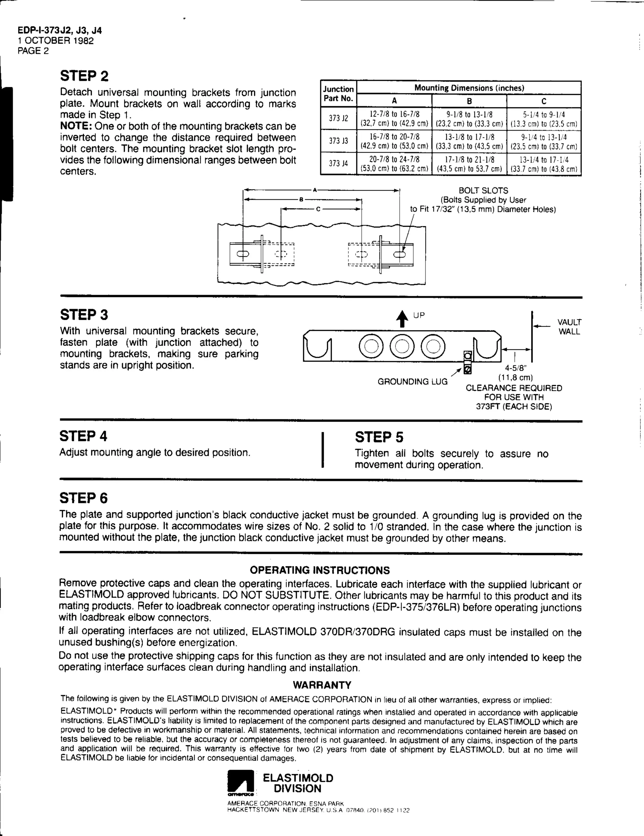
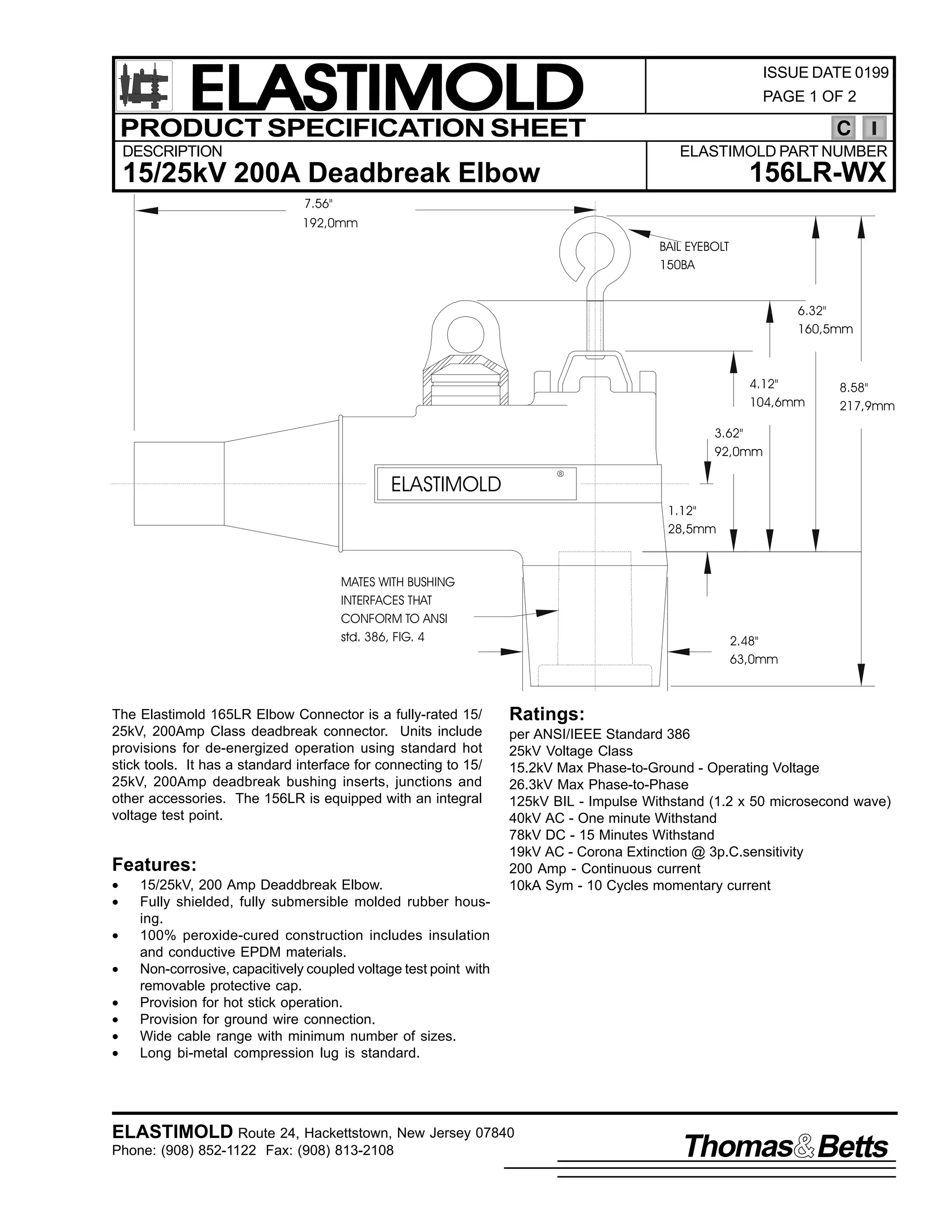
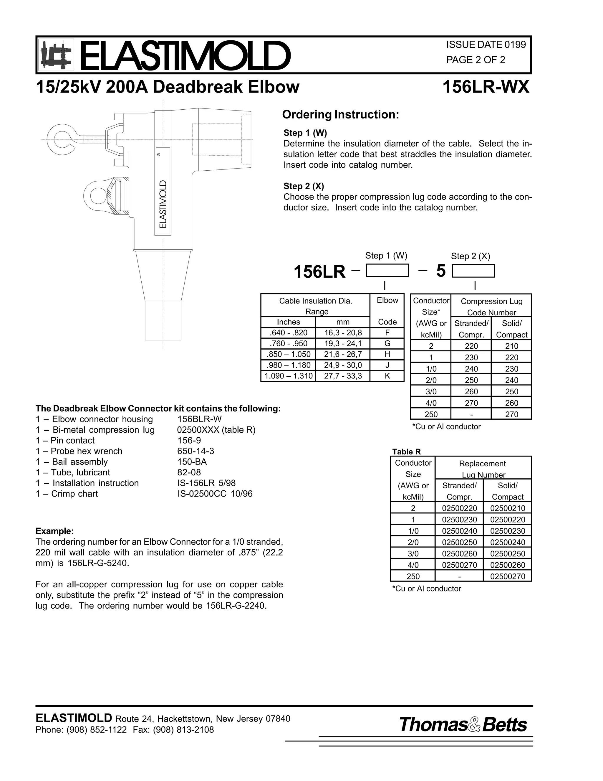
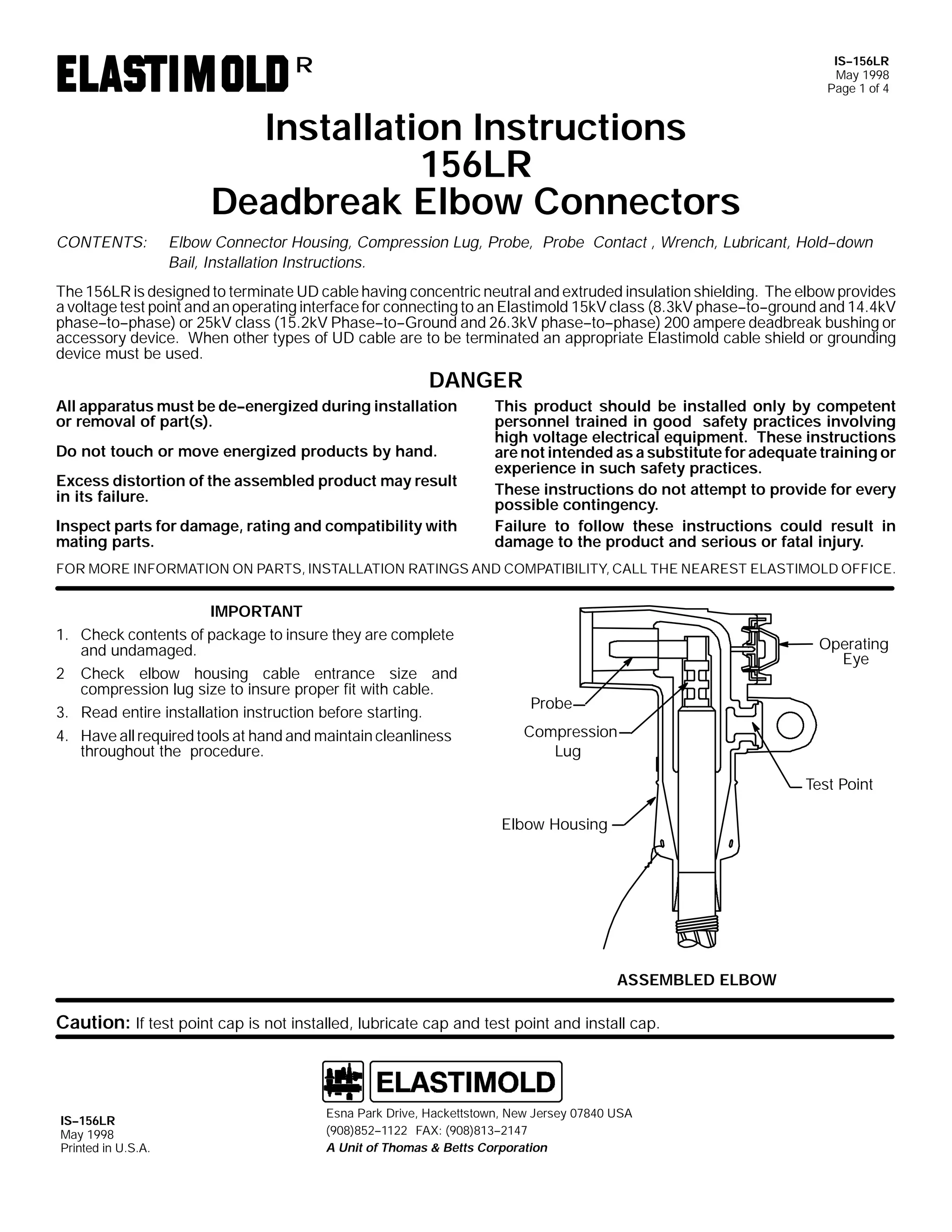
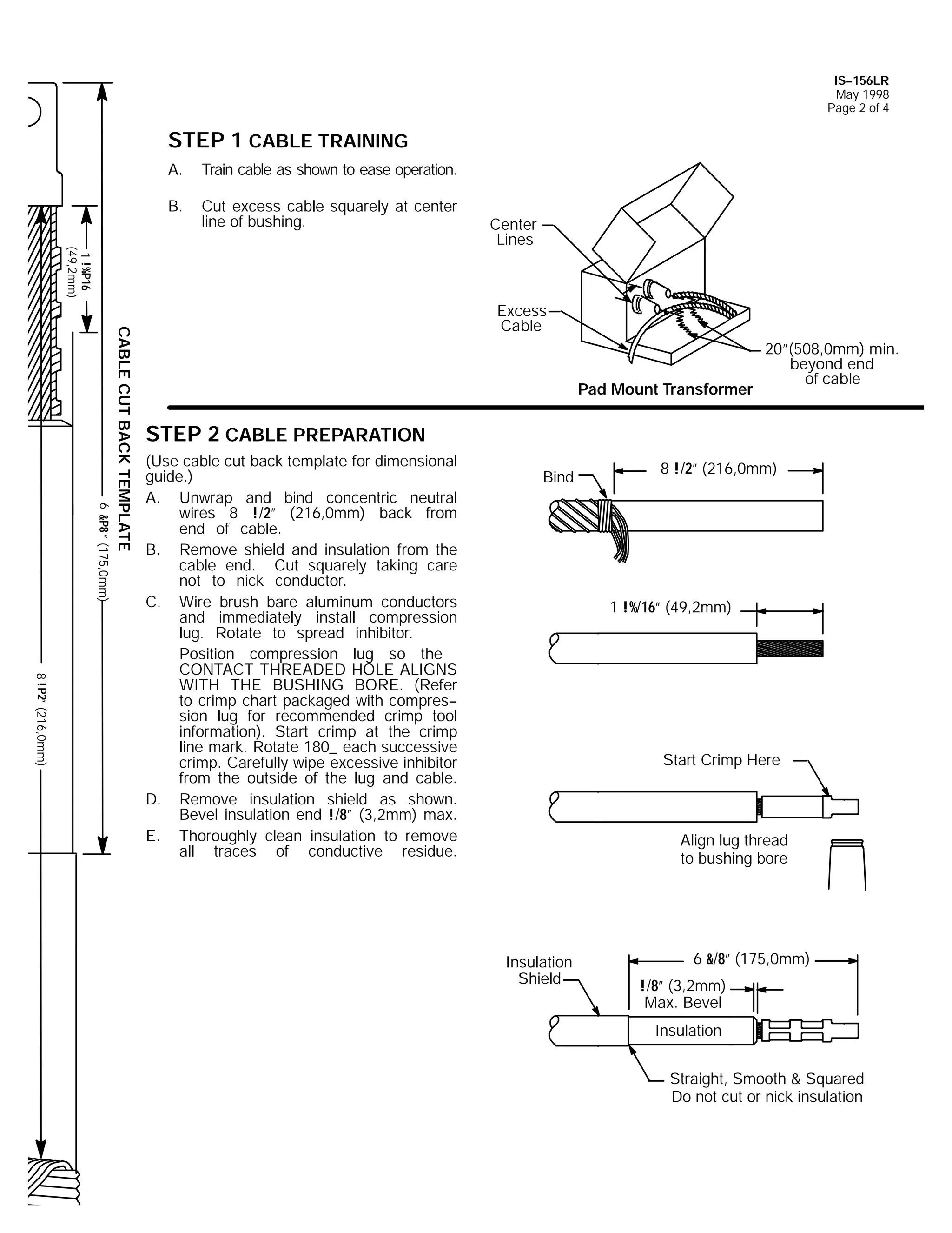
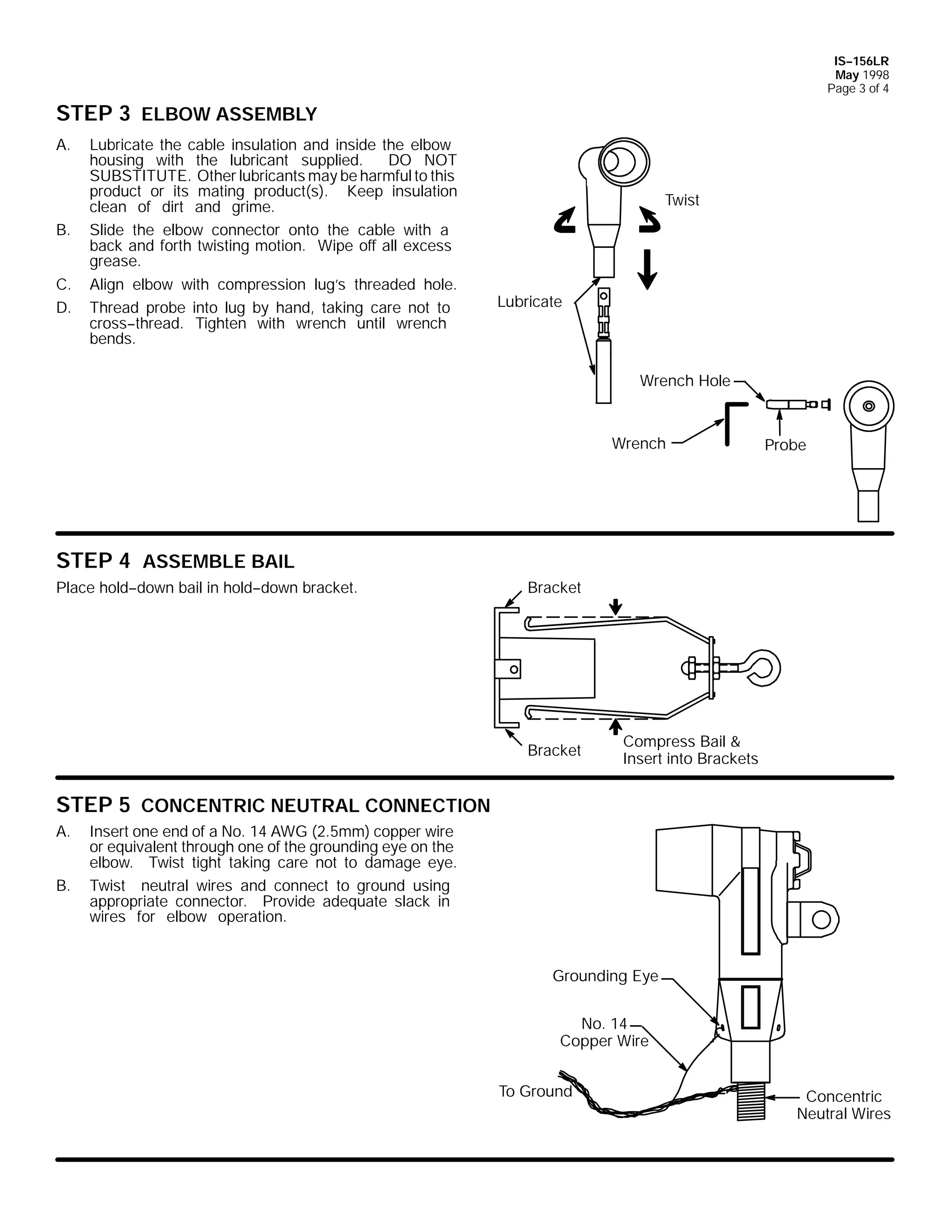
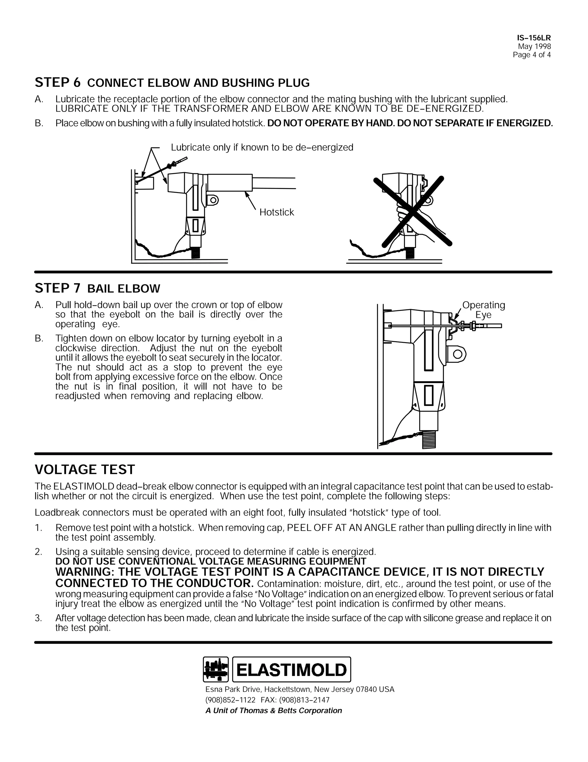
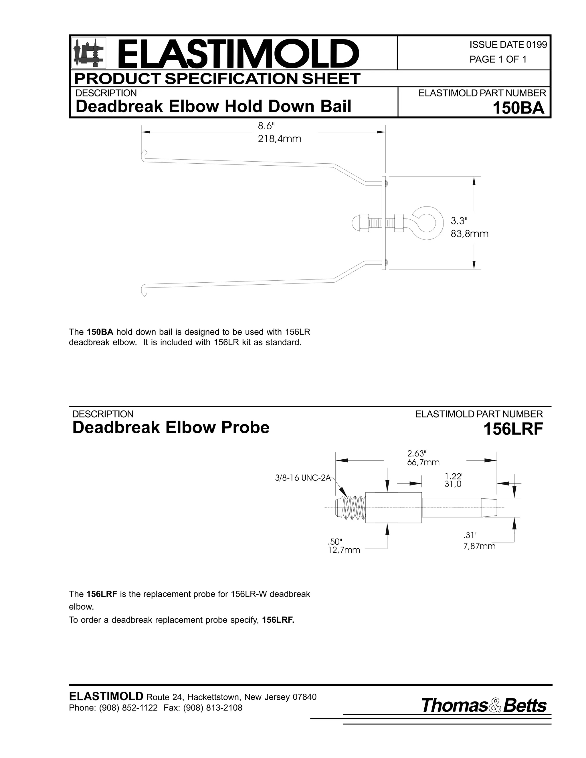
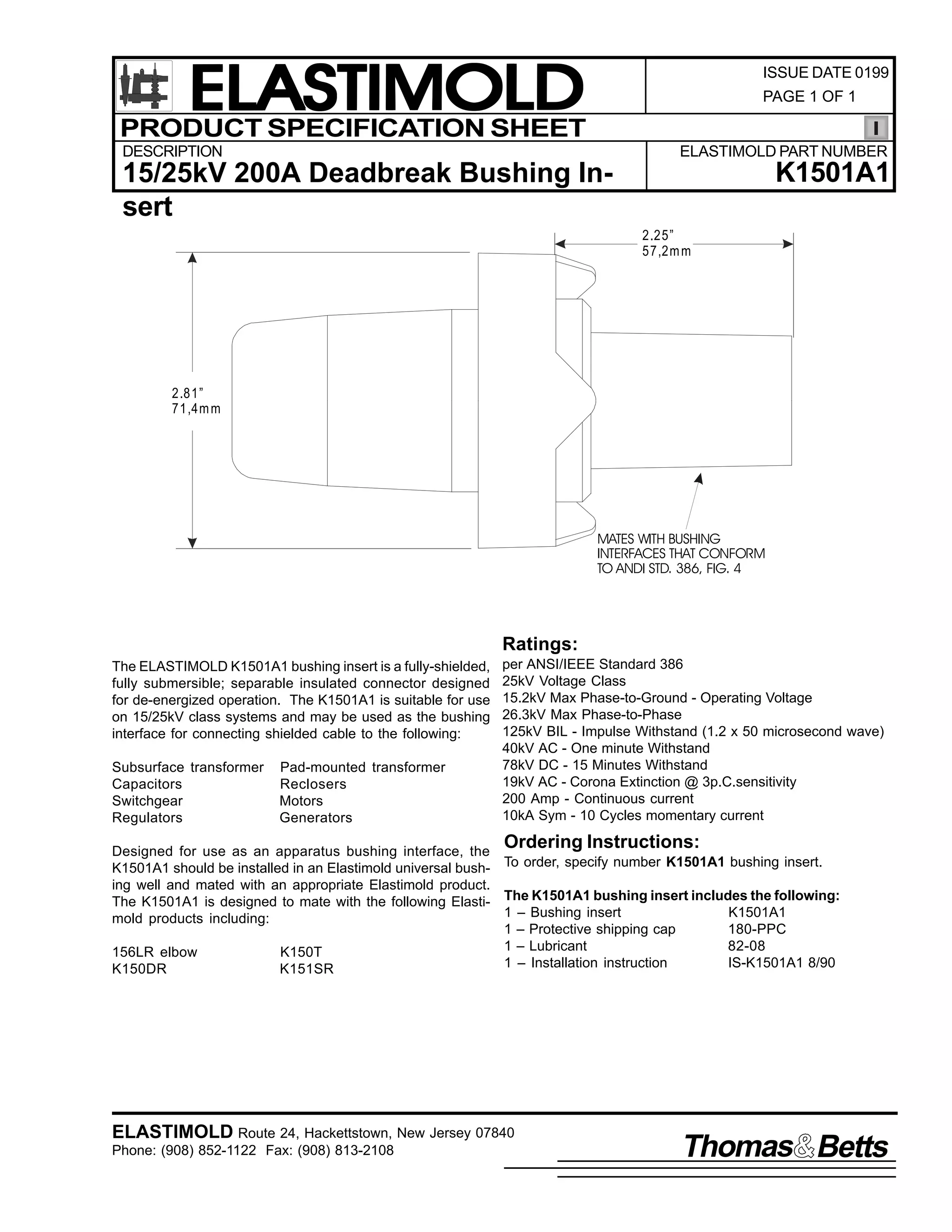

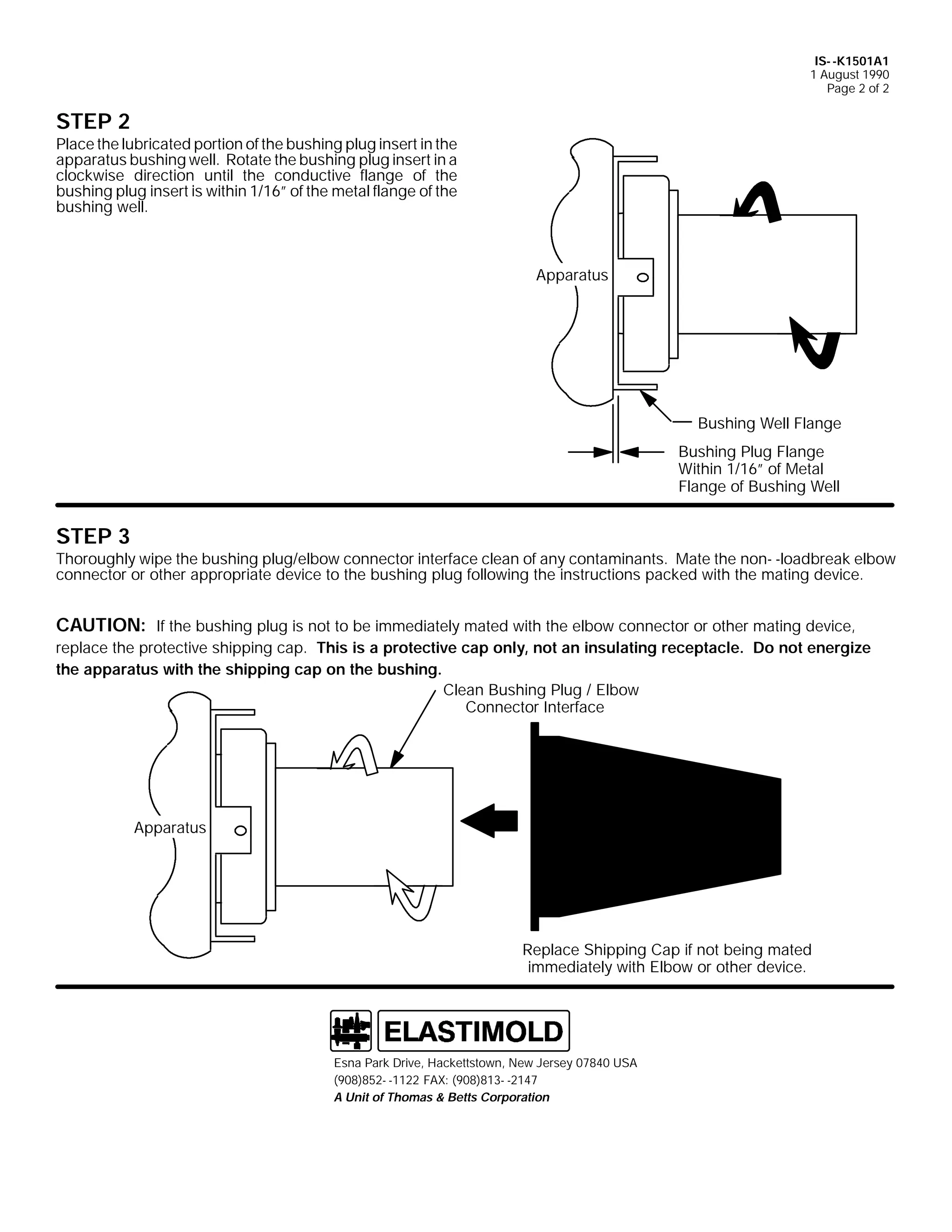
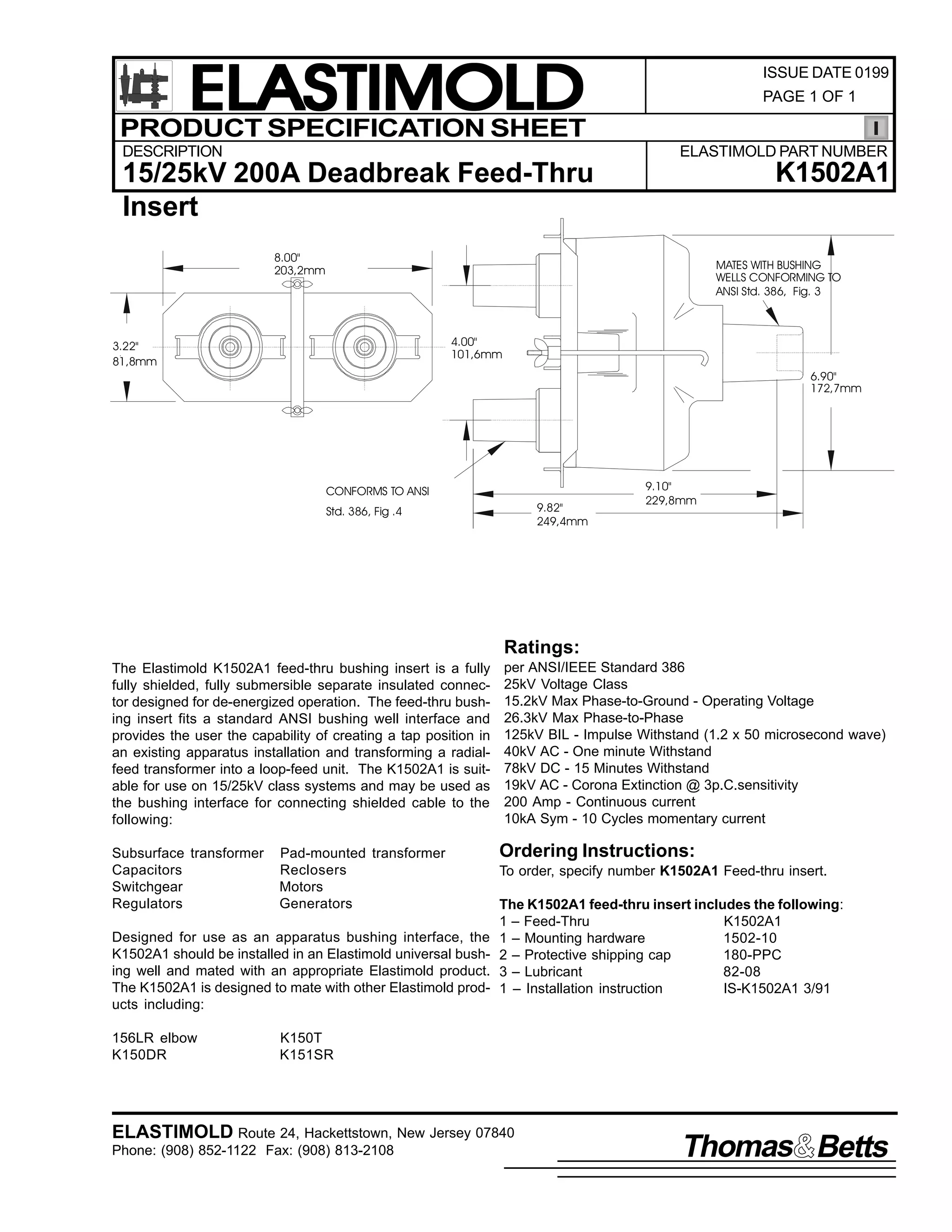
![9
,60 0.4835$4
4 0DUFK 4<<4
3DJH 4 RI 5
,QVWDOODWLRQ ,QVWUXFWLRQV
.4835$4
'HDGEUHDN )HHG0 07KUX ,QVHUW
&217(176= 'HDGEUHDN )HHG0 07KUX ,QVHUW/ 6WDLQOHVV 6WHHO 3ODWH/ %DU/ 6WDLQOHVV 6WHHO +RRN %ROWV/ 6WDLQOHVV 6WHHO :LQJ 1XWV/ /X0
EULFDQW +'2 127 68%67,787(,/ ,QVWDOODWLRQ ,QVWUXFWLRQ
7KH .4835$4 LV GHVLJQHG WR SURYLGH WKH DSSDUDWXV LQWHUIDFH DQG ORRS IHHG0 0WKUX IRU (ODVWLPROG 58N9 FODVV +4815N9 SKDVH0 0WR0 0
JURXQG DQG 5916N9 SKDVH0 0WR0 0SKDVH, GHDGEUHDN FRQQHFWLRQV1
'$1*(5
$OO DSSDUDWXV PXVW EH GH0 0HQHUJL]HG GXULQJ LQVWDOODWLRQ RU
UHPRYDO RI SDUW+V,1
'R QRW WRXFK RU PRYH HQHUJL]HG SURGXFWV E KDQG1
([FHVV GLVWRUWLRQ RI WKH DVVHPEOHG SURGXFW PD UHVXOW LQ LWV
IDLOXUH1
,QVSHFW SDUWV IRU GDPDJH/ UDWLQJ DQG FRPSDWLELOLW ZLWK PDW0
LQJ SDUWV1
7KLV SURGXFW VKRXOG EH LQVWDOOHG RQO E FRPSHWHQW SHUVRQ0
QHO WUDLQHG LQ JRRG VDIHW SUDFWLFHV LQYROYLQJ KLJK YROWDJH
HOHFWULFDO HTXLSPHQW1 7KHVH LQVWUXFWLRQV DUH QRW LQWHQGHG
DV D VXEVWLWXWH IRU DGHTXDWH WUDLQLQJ RU H[SHULHQFH LQ VXFK
VDIHW SUDFWLFHV1
7KHVH LQVWUXFWLRQV GR QRW DWWHPSW WR SURYLGH IRU HYHU SRV0
VLEOH FRQWLQJHQF1
)DLOXUH WR IROORZ WKHVH LQVWUXFWLRQV FRXOG UHVXOW LQ GDPDJH
WR WKH SURGXFW DQG VHULRXV RU IDWDO LQMXU1
7KLV SURGXFW LV VXSSOLHG ZLWK D SURWHFWLYH VKLSSLQJ FDSV1
5HPRYH WKHVH VKLSSLQJ FDSV DQG UHSODFH ZLWK WKH DSSURSUL0
DWH +9 LQVXODWHG FDS RU FRQQHFWRU EHIRUH VXEPHUJLQJ RU
HQHUJL]LQJ WKH FLUFXLW1
)25 025( ,1)250$7,21 21 3$576/ ,167$//$7,21 5$7,1*6 $1' &203$7,%,/,7</ &$// 7+( 1($5(67 (/$67,02/' 2)),&(1
,03257$17
41 &KHFN FRQWHQWV RI SDFNDJH WR LQVXUH WKH DUH FRPSOHWH DQG
XQGDPDJHG1
51 &KHFN DOO FRPSRQHQWV WR LQVXUH SURSHU ILW ZLWK FDEOH DQG2RU
PDWLQJ SURGXFWV1
61 5HDG HQWLUH LQVWDOODWLRQ LQVWUXFWLRQV EHIRUH VWDUWLQJ1
67(3 4
67(3 5
:KHQ LQVWDOOLQJ D .4835$4 IHHG0 0WKUX LQVHUW LQ D FODPSDEOH DS0
SDUDWXV EXVKLQJ ZHOO/ FKHFN WKH KHLJKW RI WKH PRXQWLQJ EROWV1
+DUGZDUH ZKLFK SURWUXGHV PRUH WKDQ 425l +45PP, DERYH WKH
WRS RI WKH DSSDUDWXV EXVKLQJ ZHOO ZLOO SUHYHQW WKH IHHG0 0WKUX LQ0
VHUW IURP EHLQJ DVVHPEOHG1 ,I WKLV FRQGLWLRQ H[LVWV/ FRQVXOW ZLWK
DSSDUDWXV PDQXIDFWXUHU RQ SURSHU PHWKRG WR VKRUWHQ EROWV1
451:PP
1833 LQ1 PD[1
IRU DOO ZHOOV
71 +DYH DOO UHTXLUHG WRROV DW KDQG DQG PDLQWDLQ FOHDQOLQHVV
WKURXJKRXW WKH SURFHGXUH1
,QVSHFW WKH DSSDUDWXV EXVKLQJ ZHOO WR HQVXUH LW LV GU DQG IUHH
IURP DOO FRQWDPLQDQWV1 /XEULFDWH WKH EXVKLQJ ZHOO LQWHUIDFH DQG
FXII DUHD RI WKH IHHG0 0WKUX LQVHUW ZLWK WKH VXSSOLHG OXEULFDQW RU
(/$67,02/' DSSURYHG OXEULFDQWV1 '2 127 68%67,787(1
2WKHU OXEULFDQWV PD EH KDUPIXO WR WKLV SURGXFW DQG LWV PDWLQJ
SURGXFWV1
/XEULFDWH
&ODPS
3URWHFWLYH
&DSV
7DQN
,60 0.4835$4
4 0DUFK 4<<4
3DJH 5 RI 5](https://image.slidesharecdn.com/elastimold-140130102426-phpapp02/75/Elastimold-Connectors-Loadbreak-Deadbreak-Elbow-Bolted-Tee-Connectors-HV-MV-700-Series-254-2048.jpg)
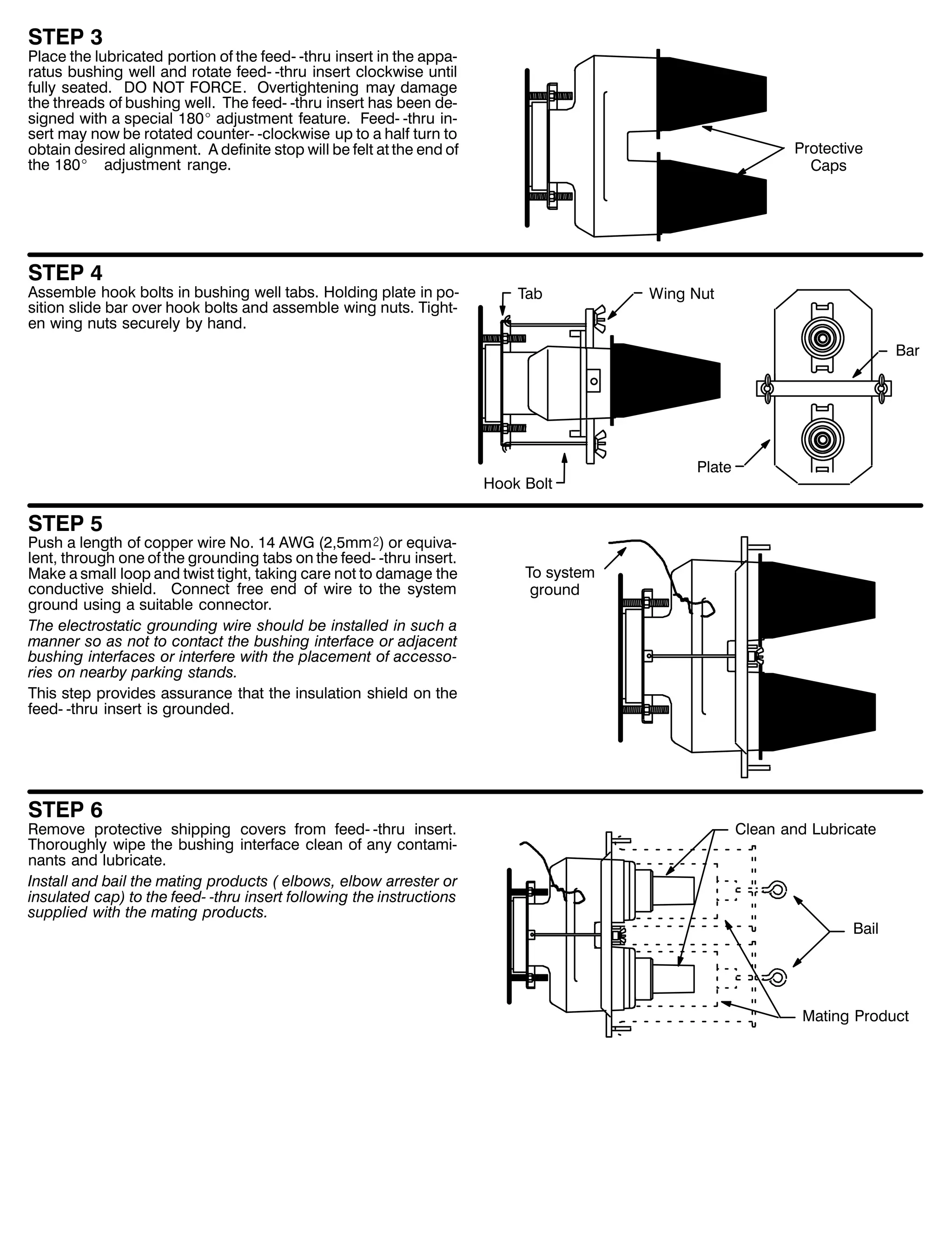
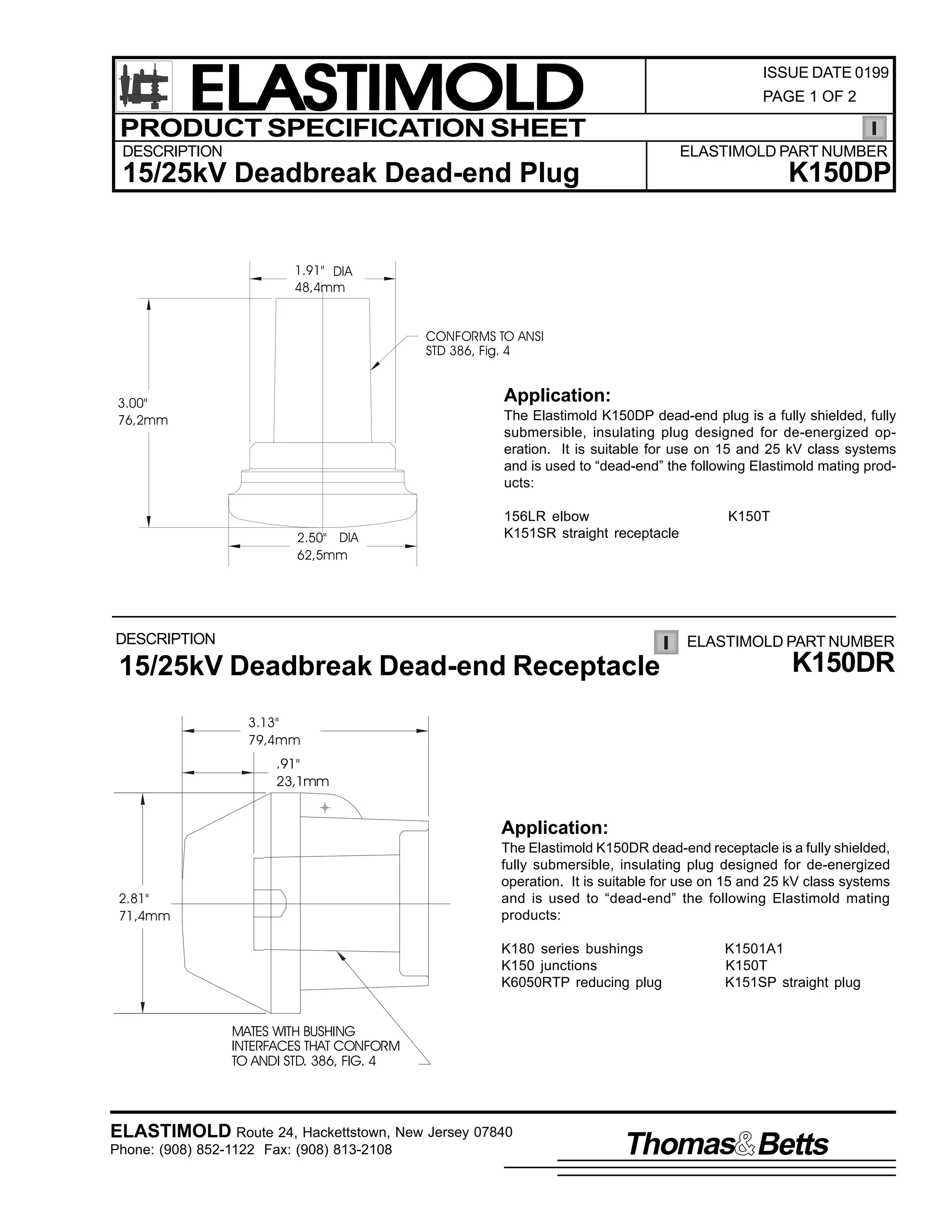
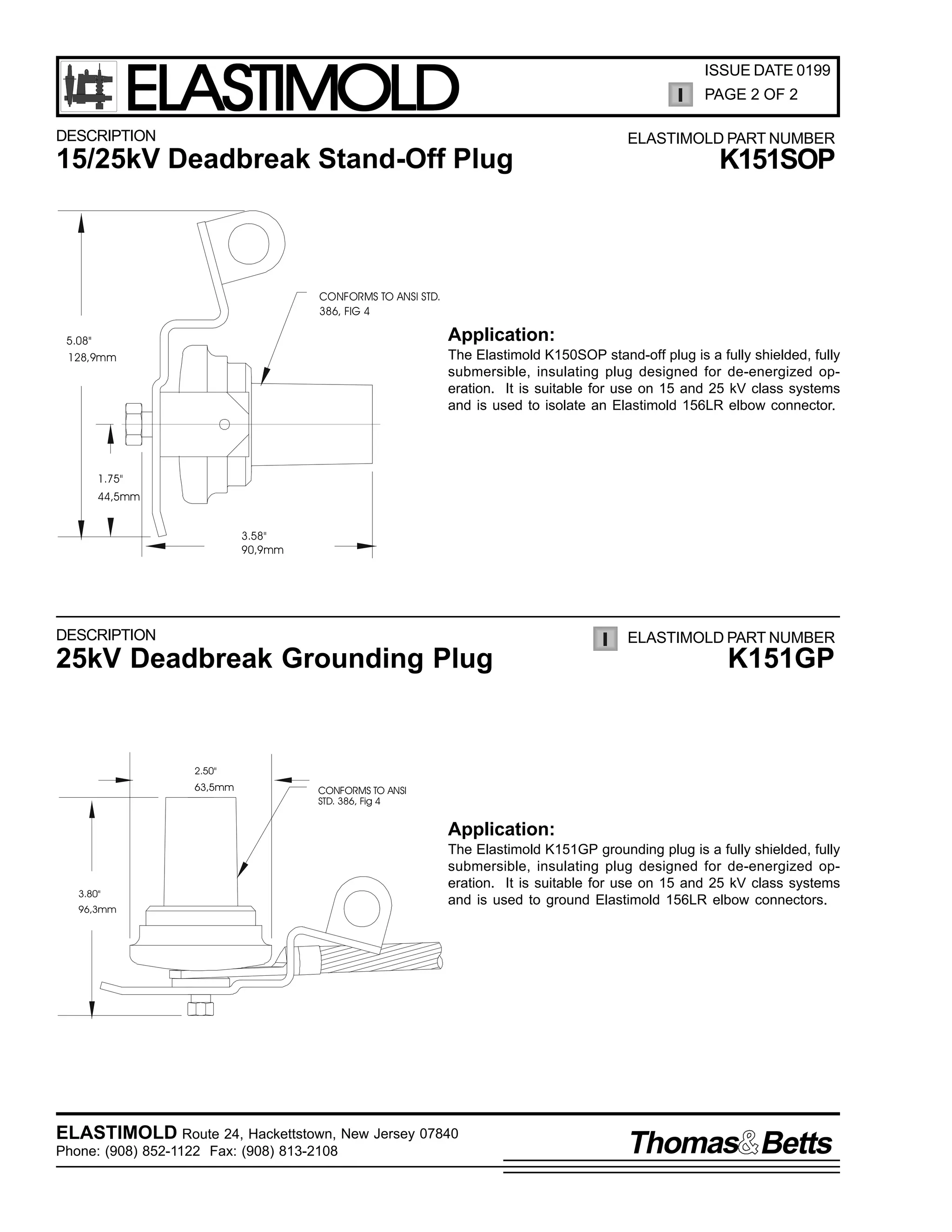
![9
,QVWDOODWLRQ ,QVWUXFWLRQV
483'3 $1' .483'3
'HDG0 0(QG 3OXJ
,60 0483'32.483'3 +5HY $,
63 -XQH 4<<7
3DJH 4 RI 4
&217(176=
'HDG0 0HQG 3OXJ/ 1ORQ 9HQWLQJ 5RG/ ,QVWDOODWLRQ ,QVWUXFWLRQV1
7KH (ODVWLPROG 483'3 DQG .483'3 GHDG0 0HQG SOXJV DUH XVHG WR LQVXODWH WKH UHFHSWDFOH SRUWLRQ RI WKH IROORZLQJ (ODVWLPROG SURG0
XFWV=
487/5/ .487/5 DQG 489/5 HOERZ FRQQHFWRUV
4837 DQG .4837 WHH FRQQHFWRUV
48465 DQG .48465 VWUDLJKW UHFHSWDFOHV
'$1*(5
$OO DSSDUDWXV PXVW EH GH0 0HQHUJL]HG GXULQJ LQVWDOODWLRQ
RU UHPRYDO RI SDUW+V,1
'R QRW WRXFK RU PRYH HQHUJL]HG SURGXFWV E KDQG1
([FHVV GLVWRUWLRQ RI WKH DVVHPEOHG SURGXFW PD UHVXOW LQ
LWV IDLOXUH1
,QVSHFW SDUWV IRU GDPDJH/ UDWLQJ DQG FRPSDWLELOLW ZLWK
PDWLQJ SDUWV1
7KLV SURGXFW VKRXOG EH LQVWDOOHG RQO E FRPSHWHQW SHU0
VRQQHO WUDLQHG LQ JRRG VDIHW SUDFWLFHV LQYROYLQJ KLJK
YROWDJH HOHFWULFDO HTXLSPHQW1 7KHVH LQVWUXFWLRQV DUH QRW
LQWHQGHG DV D VXEVWLWXWH IRU DGHTXDWH WUDLQLQJ RU H[SHUL0
HQFH LQ VXFK VDIHW SUDFWLFHV1
7KHVH LQVWUXFWLRQV GR QRW DWWHPSW WR SURYLGH IRU HYHU
SRVVLEOH FRQWLQJHQF1
)DLOXUH WR IROORZ WKHVH LQVWUXFWLRQV ZLOO UHVXOW LQ GDPDJH
WR WKH SURGXFW DQG VHULRXV RU IDWDO LQMXU1
)25 025( ,1)250$7,21 21 3$576/ ,167$//$7,21 5$7,1*6 $1' &203$7,%,/,7</ &$// 7+( 1($5(67 (/$67,02/' 2)),&(1
,03257$17
41 &KHFN FRQWHQWV RI SDFNDJH WR LQVXUH WKH DUH FRPSOHWH
DQG XQGDPDJHG1
51 &KHFN DOO FRPSRQHQWV WR LQVXUH SURSHU ILW ZLWK FDEOH
DQG2RU PDWLQJ SURGXFWV1
67(3 4
,QVSHFW WKH PDWLQJ UHFHSWDFOH LQWHUIDFH WR PDNH VXUH LW LV GU
DQG FOHDU RI FRQWDPLQDQWV1 5HPRYH WKH SURWHFWLYH VKLSSLQJ
FDS IURP WKH GHDG0 0HQG SOXJ1
61 5HDG HQWLUH LQVWDOODWLRQ LQVWUXFWLRQV EHIRUH VWDUWLQJ1
71 +DYH DOO UHTXLUHG WRROV DW KDQG DQG PDLQWDLQ FOHDQOLQHVV
WKURXJKRXW WKH SURFHGXUH1
67(3 5
/XEULFDWH WKH QRZ H[SRVHG LQWHUIDFH DUHD ZLWK WKH OXEULFDQW
VXSSOLHG1 '2 127 68%67,787(1
5HPRYH 6KLSSLQJ FDS
/XEULFDWH
67(3 6
,QVHUW WKH QORQ YHQWLQJ URG LQWR WKH UHFHSWDFOH DUHD RI WKH SURGXFW GHVLUHG WR EH GHDG0 0HQGHG WR H[KDXVW WKH DLU GXULQJ DVVHPEO
,QVHUW WKH GHDG0 0HQG SOXJ LQWR WKH UHFHSWDFOH DUHD DV IDU DV SRVVLEOH1 5HPRYH WKH QORQ YHQWLQJ URG WR FRPSOHWH WKH LQVWDOODWLRQ1
1ORQ 9HQW 5RG
5HFHSWDFOH $UHD
RI 0DWLQJ 3URGXFW](https://image.slidesharecdn.com/elastimold-140130102426-phpapp02/75/Elastimold-Connectors-Loadbreak-Deadbreak-Elbow-Bolted-Tee-Connectors-HV-MV-700-Series-258-2048.jpg)
![9
,QVWDOODWLRQ ,QVWUXFWLRQV
483'5 $1' .483'5
'HDG0 0(QG 5HFHSWDFOH
,60 0483'52.483'5 +5HY %,
63 -XQH 4<<7
3DJH 4 RI 4
&217(176=
'HDG0 0HQG 5HFHSWDFOH/ 1ORQ 9HQWLQJ 5RG/ ,QVWDOODWLRQ ,QVWUXFWLRQV1
7KH (ODVWLPROG 483'5 DQG .483'5 GHDG0 0HQG UHFHSWDFOHV DUH XVHG WR LQVXODWH WKH SOXJ SRUWLRQ RI WKH IROORZLQJ (ODVWLPROG
SURGXFWV=
4834$4 DQG .4834$4 EXVKLQJ LQVHUWV
48463 DQG .48463 VWUDLJKW SOXJV
4834-6 ) -7 DQG .4834-6 ) -7 MXQFWLRQV
933573 DQG .933573 UHGXFLQJ WDS SOXJV
4837 DQG .4837 WHH FRQQHFWRUV
9335736 DQG .9335736 UHGXFLQJ WDS SOXJV ZLWK VWXG
.4835$4 IHHG0 0WKUX LQVHUW
.4834)7 IHHG0 0WKUX
'$1*(5
$OO DSSDUDWXV PXVW EH GH0 0HQHUJL]HG GXULQJ LQVWDOODWLRQ
RU UHPRYDO RI SDUW+V,1
'R QRW WRXFK RU PRYH HQHUJL]HG SURGXFWV E KDQG1
([FHVV GLVWRUWLRQ RI WKH DVVHPEOHG SURGXFW PD UHVXOW LQ
LWV IDLOXUH1
,QVSHFW SDUWV IRU GDPDJH/ UDWLQJ DQG FRPSDWLELOLW ZLWK
PDWLQJ SDUWV1
7KLV SURGXFW VKRXOG EH LQVWDOOHG RQO E FRPSHWHQW SHU0
VRQQHO WUDLQHG LQ JRRG VDIHW SUDFWLFHV LQYROYLQJ KLJK
YROWDJH HOHFWULFDO HTXLSPHQW1 7KHVH LQVWUXFWLRQV DUH QRW
LQWHQGHG DV D VXEVWLWXWH IRU DGHTXDWH WUDLQLQJ RU H[SHUL0
HQFH LQ VXFK VDIHW SUDFWLFHV1
7KHVH LQVWUXFWLRQV GR QRW DWWHPSW WR SURYLGH IRU HYHU
SRVVLEOH FRQWLQJHQF1
)DLOXUH WR IROORZ WKHVH LQVWUXFWLRQV FRXOG UHVXOW LQ GDP0
DJH WR WKH SURGXFW DQG VHULRXV RU IDWDO LQMXU1
)25 025( ,1)250$7,21 21 3$576/ ,167$//$7,21 5$7,1*6 $1' &203$7,%,/,7</ &$// 7+( 1($5(67 (/$67,02/' 2)),&(1
,03257$17
41 &KHFN FRQWHQWV RI SDFNDJH WR LQVXUH WKH DUH FRP0 0
SOHWH DQG XQGDPDJHG1
51 &KHFN DOO FRPSRQHQWV WR LQVXUH SURSHU ILW ZLWK FDEOH
DQG2RU PDWLQJ SURGXFWV1
61 5HDG HQWLUH LQVWDOODWLRQ LQVWUXFWLRQV EHIRUH VWDUWLQJ1
71 +DYH DOO UHTXLUHG WRROV DW KDQG DQG PDLQWDLQ FOHDQOL0 0
QHVV WKURXJKRXW WKH SURFHGXUH1
67(3 4
/XEULFDWH WKH SOXJ SRUWLRQ RI WKH PDWLQJ SURGXFW GHVLUHG WR EH
GHDG0 0HQGHG ZLWK WKH OXEULFDQW VXSSOLHG1 .HHS JUHDVH DZD
IURP WKH PHWDO FHQWHU HQG RI WKH SOXJ1
'2 127 68%67,787(1
3OXJ 3RUWLRQ
/XEULFDWH
67(3 5
,QVHUW WKH QORQ YHQWLQJ URG LQWR WKH GHDG0 0HQG UHFHSWDFOH WR
H[KDXVW WKH DLU GXULQJ DVVHPEO1 3XVK WKH GHDG0 0HQG UHFHS0
WDFOH RQWR WKH SOXJ DV IDU DV SRVVLEOH XQWLO WKH WZR SDUWV EXWW
WRJHWKHU1 5HPRYH WKH QORQ YHQWLQJ URG1
1ORQ 9HQW 5RG
67(3 6
&RQQHFW D JURXQG ZLUH WR WKH JURXQGLQJ HH RI WKH GHDG0 0
HQG UHFHSWDFOH DQG WR VVWHP JURXQG1 7KH JURXQG ZLUH
VKRXOG EH 1R1 47 $:* VL]H +5PP5, RU ODUJHU1
3OXJ
'HDG0 0HQG 5HFHSWDFOH
7R *URXQG](https://image.slidesharecdn.com/elastimold-140130102426-phpapp02/75/Elastimold-Connectors-Loadbreak-Deadbreak-Elbow-Bolted-Tee-Connectors-HV-MV-700-Series-259-2048.jpg)
![9
,60 0484623 +5(91 &,
63 -DQXDU 4<<4
3DJH 4
2SHUDWLQJ ,QVWUXFWLRQV
4846232.484623
'HDGEUHDN ,QVXODWHG 3DUNLQJ %XVKLQJ
&217(176=
6WDQG 2II 3OXJ +FRPSOHWH ZLWK PRXQWLQJ KDUGZDUH,/ +ROG0 0GRZQ %DLO $VVHPEO/ /XEULFDQW/ 2SHUDWLQJ
,QVWUXFWLRQV
7KH 484623 LV GHVLJQHG WR WHUPLQDWH WKH IHPDOH GHDGEUHDN FRQQHFWRU LQWHUIDFH RI WKH 487/5 RU WKH 489/5 (OERZV +RWKHU
SURGXFWV VKRXOG QRW EH XVHG VLQFH WKH 484623 EDLO LV GHVLJQHG WR VHFXUH HOERZV RQO, UDWHG IRU 48N9 FODVV +;16N9 SKDVH0 0
WR0 0JURXQG DQG 4717N9 SKDVH0 0WR SKDVH, 533 DPSHUH1 7KH .484623 SURYLGHV WKH VDPH IXQFWLRQ IRU WKH 58N9 FODVV +4815N9
SKDVH0 0WR0 0JURXQG DQG 5916N9 SKDVH0 0WR0 0SKDVH,533 DPSHUH UDWLQJ1
'$1*(5
$OO DSSDUDWXV PXVW EH GH0 0HQHUJL]HG GXULQJ LQVWDOODWLRQ
RU UHPRYDO RI SDUW+V,1
SHUVRQQHO WUDLQHG LQ JRRG VDIHW SUDFWLFHV LQYROYLQJ
KLJK YROWDJH HOHFWULFDO HTXLSPHQW1 7KHVH LQVWUXFWLRQV
DUH QRW LQWHQGHG DV D VXEVWLWXWH IRU DGHTXDWH WUDLQLQJ RU
H[SHULHQFH LQ VXFK VDIHW SUDFWLFHV1
'R QRW WRXFK RU PRYH HQHUJL]HG FDEOHV DQG2RU SURGXFWV
E KDQG1
7KHVH LQVWUXFWLRQV GR QRW DWWHPSW WR SURYLGH IRU HYHU
SRVVLEOH FRQWLQJHQF1
([FHVV GLVWRUWLRQ RI WKH DVVHPEOHG SURGXFW PD UHVXOW
)DLOXUH WR IROORZ WKHVH LQVWUXFWLRQV FRXOG UHVXOW LQ GDP0
LQ LWV IDLOXUH1
DJH WR WKH SURGXFW DQG VHULRXV RU IDWDO LQMXU1
,QVSHFW SDUWV IRU GDPDJH/ UDWLQJ DQG FRPSDWLELOLW ZLWK
7KLV SURGXFW LV VXSSOLHG ZLWK D SURWHFWLYH VKLSSLQJ FDS1
PDWLQJ SDUWV1
5HPRYH WKLV VKLSSLQJ FDS DQG UHSODFH ZLWK WKH DSSUR0
SULDWH +9 LQVXODWHG FDS RU FRQQHFWRU EHIRUH VXEPHUJ0
7KLV SURGXFW VKRXOG EH LQVWDOOHG RQO E FRPSHWHQW
LQJ RU HQHUJL]LQJ WKH FLUFXLW1
)25 025( ,1)250$7,21 21 3$576/ ,167$//$7,21 5$7,1*6 $1' &203$7,%,/,7</ &$// 7+( 1($5(67 (/$60
7,02/' 2)),&(1
,03257$17
41 &KHFN FRQWHQWV RI SDFNDJH WR LQVXUH LW LV FRPSOHWH
DQG XQGDPDJHG1
51 &KHFN DOO FRPSRQHQWV WR LQVXUH SURSHU ILW ZLWK FDEOH
DQG2RU PDWLQJ SURGXFWV1
61 5HDG HQWLUH LQVWDOODWLRQ LQVWUXFWLRQV EHIRUH VWDUWLQJ1
71 +DYH DOO UHTXLUHG WRROV DW KDQG DQG REVHUYH FOHDQOL0 0
QHVV WKURXJKRXW WKH SURFHGXUH1
67(3 4
5HPRYH SURWHFWLYH VKLSSLQJ FDS DQG FOHDQ WKH PDWLQJ LQ0
WHUIDFH RI WKH LQVXODWHG SDUNLQJ EXVKLQJ1 /XEULFDWH WKLV
VXUIDFH1 8VH RQO WKH VXSSOLHG OXEULFDQW RU (/$67,02/'
DSSURYHG OXEULFDQWV1 '2 127 68%67,787(1 2WKHU OXEUL0
FDQWV PD EH KDUPIXO WR WKLV SURGXFW DQG LWV PDWLQJ SURG0
XFWV1 $OZDV UHSODFH WKH SURWHFWLYH FDS ZKHQ WKH LQVX0
ODWHG SDUNLQJ EXVKLQJ LV QRW LQ XVH1
%DLO
5HPRYH 6KLSSLQJ &DS
&OHDQ DQG /XEULFDWH](https://image.slidesharecdn.com/elastimold-140130102426-phpapp02/75/Elastimold-Connectors-Loadbreak-Deadbreak-Elbow-Bolted-Tee-Connectors-HV-MV-700-Series-260-2048.jpg)
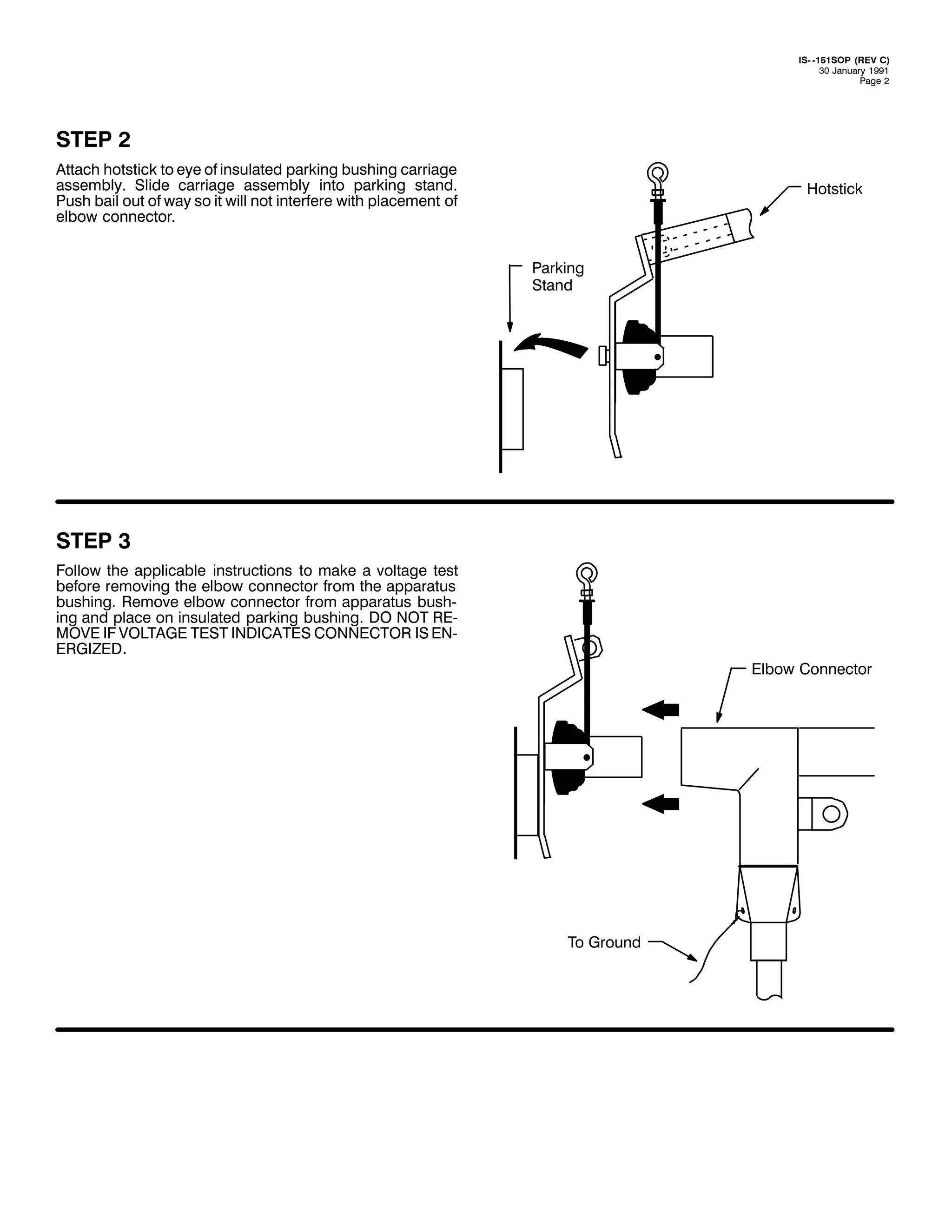
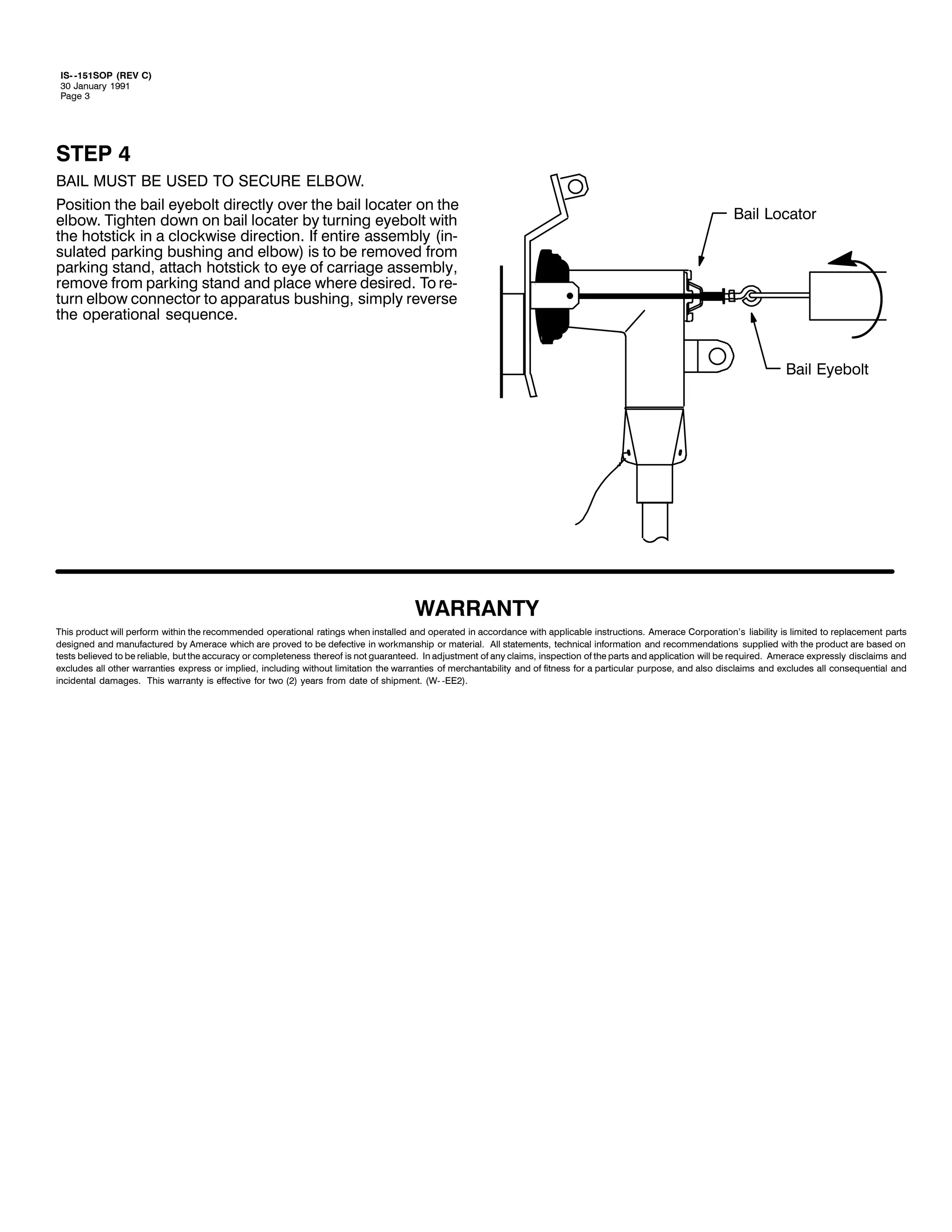
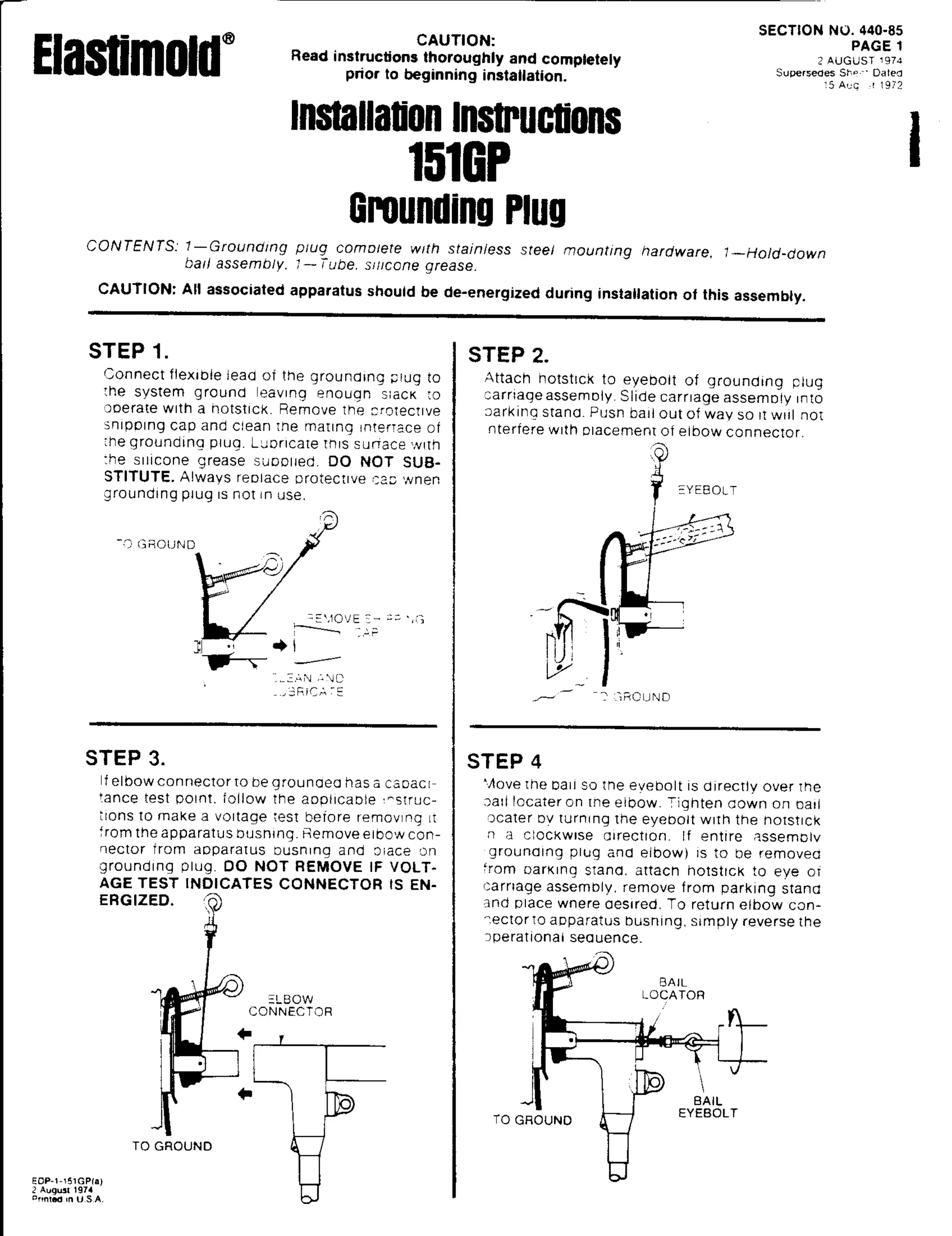
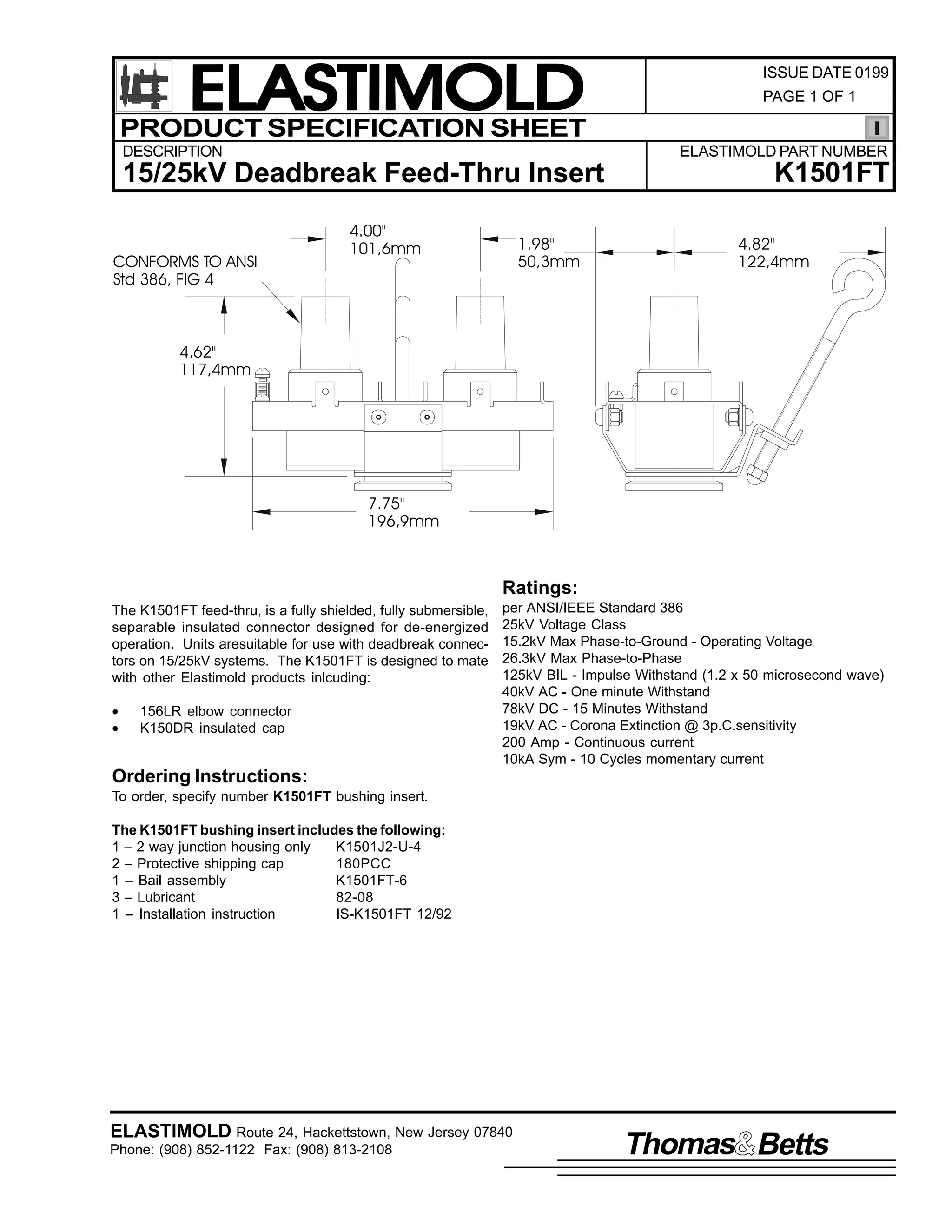
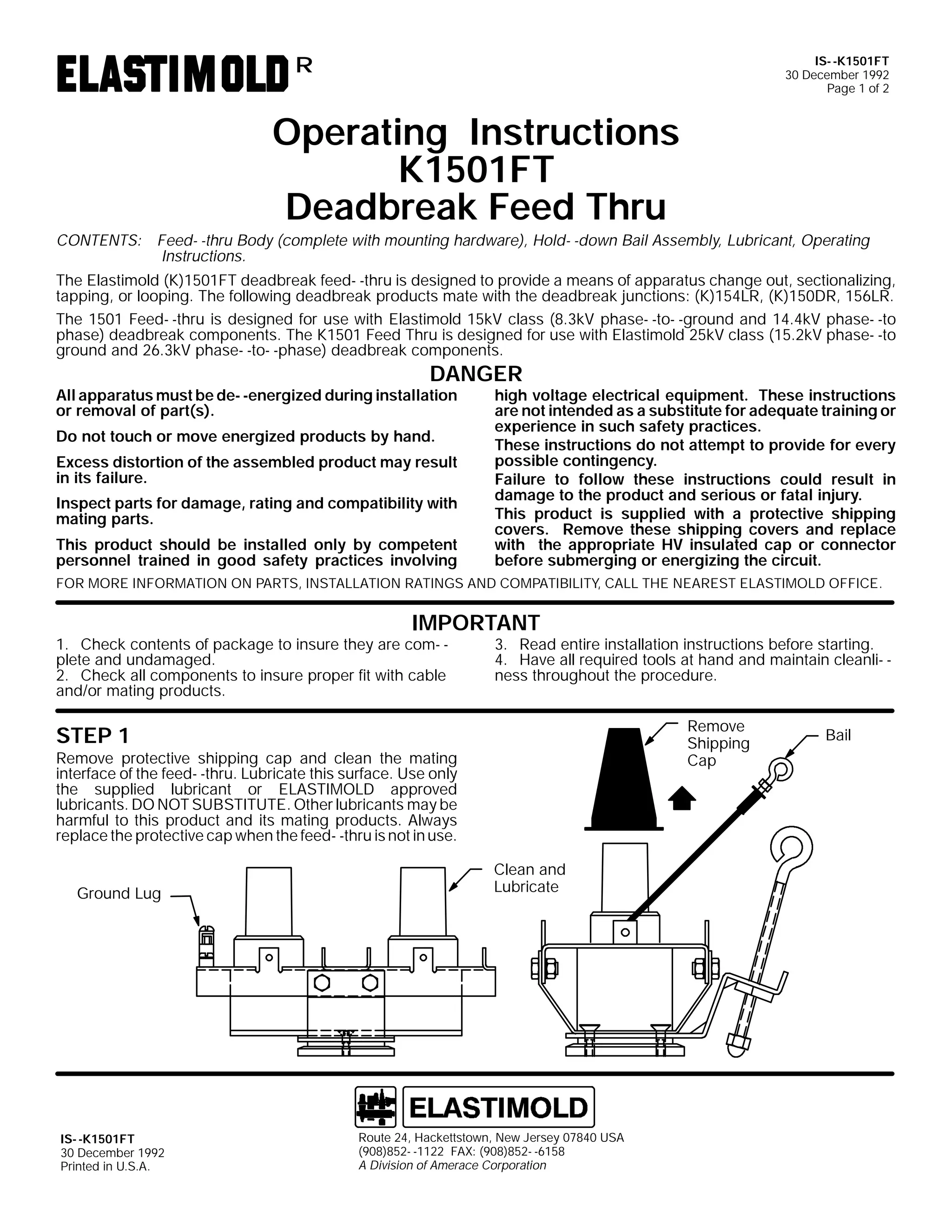
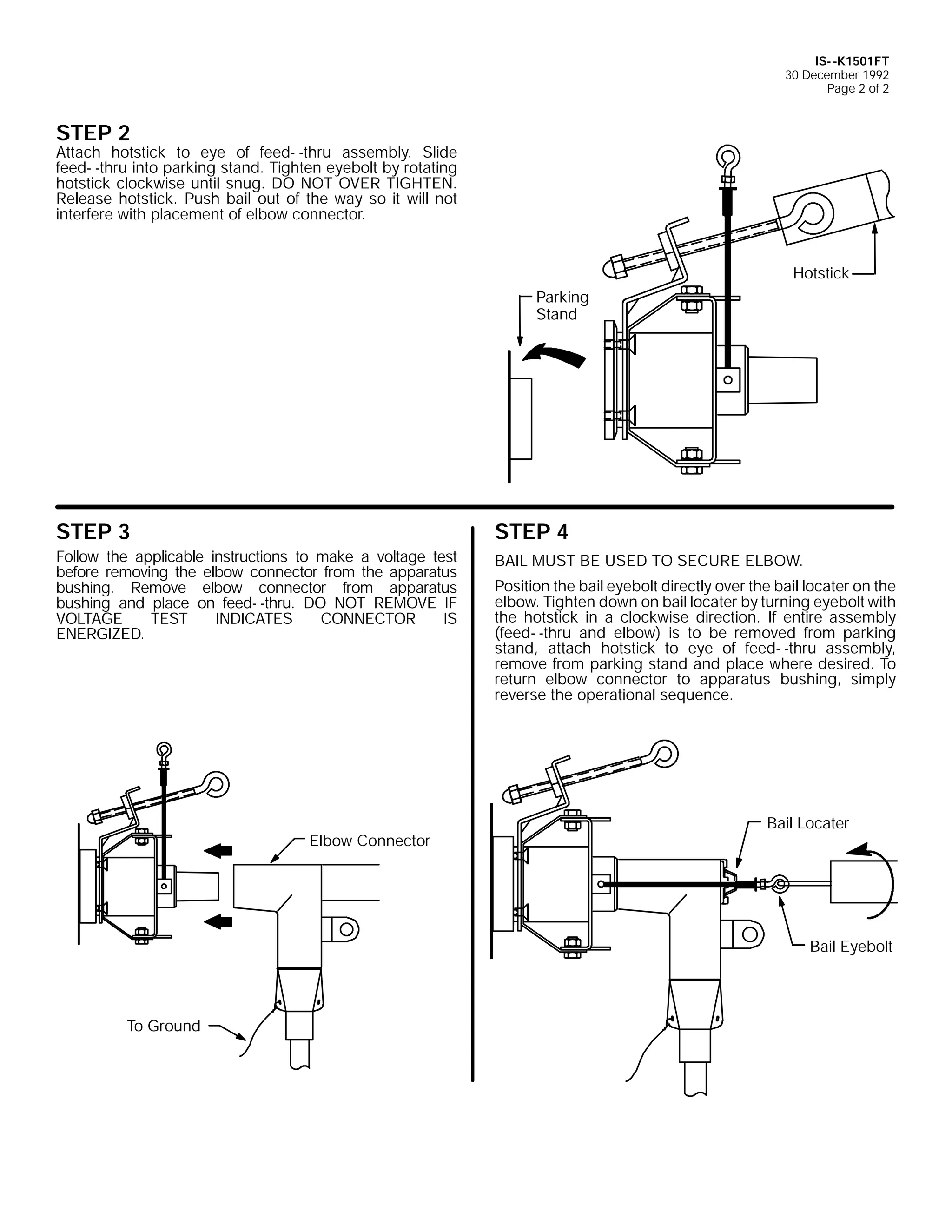
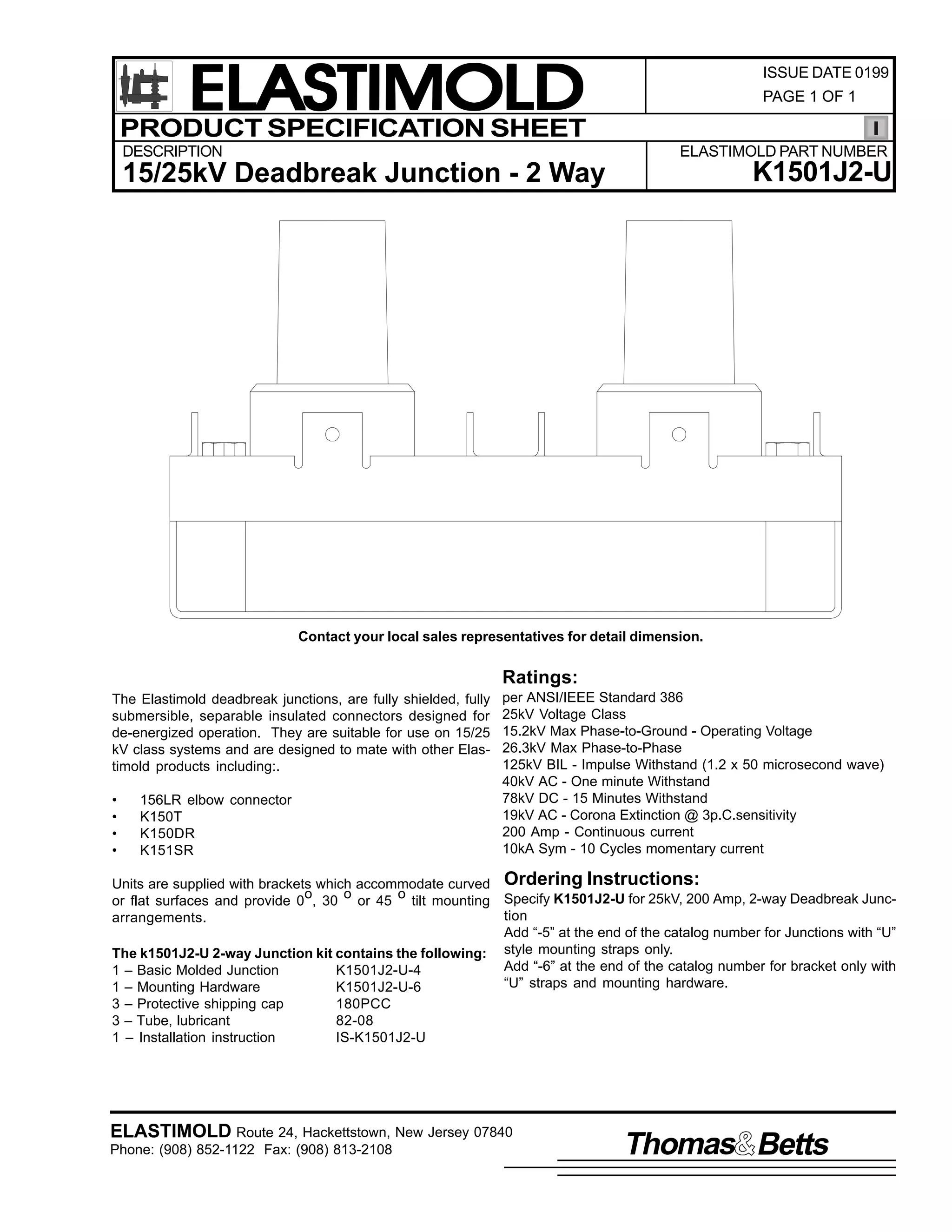

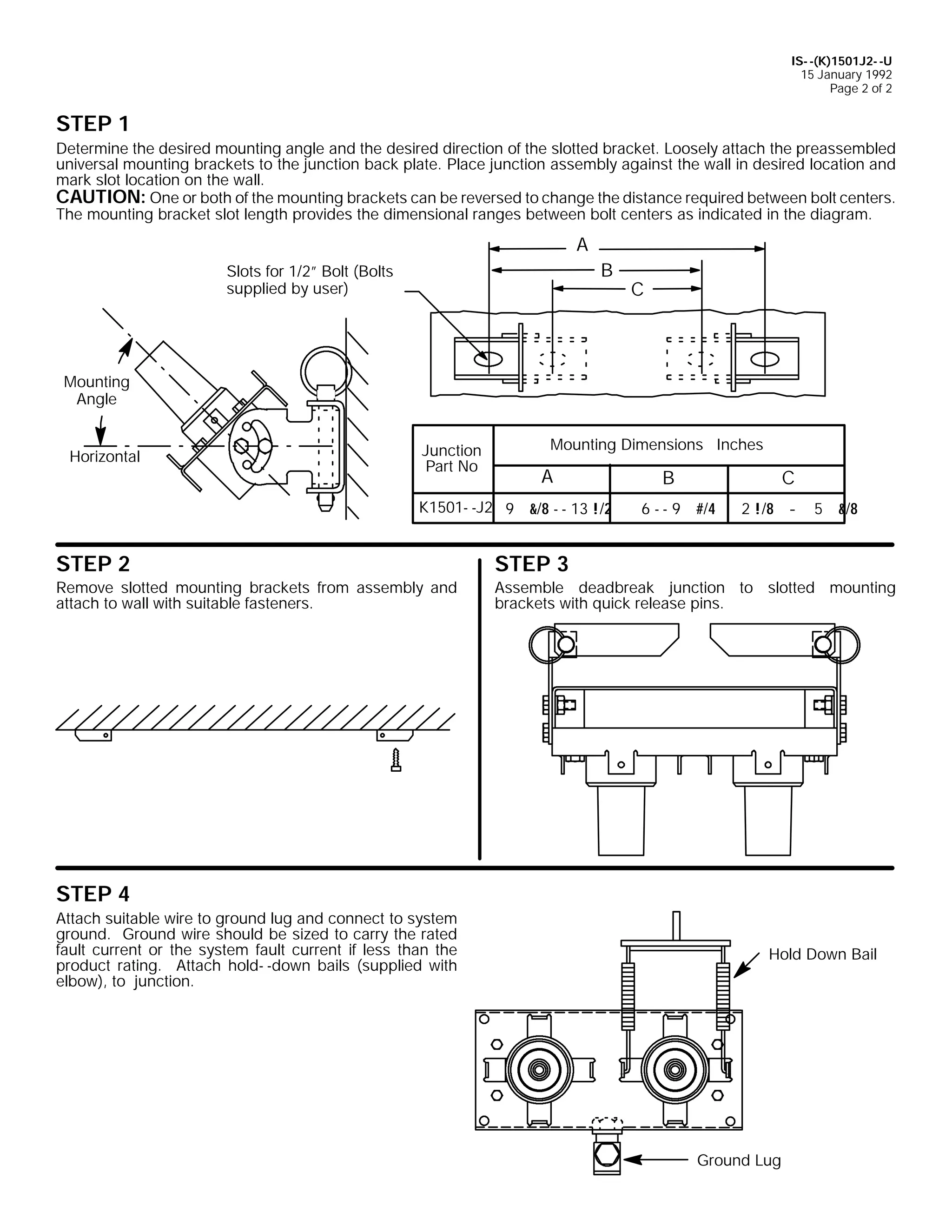
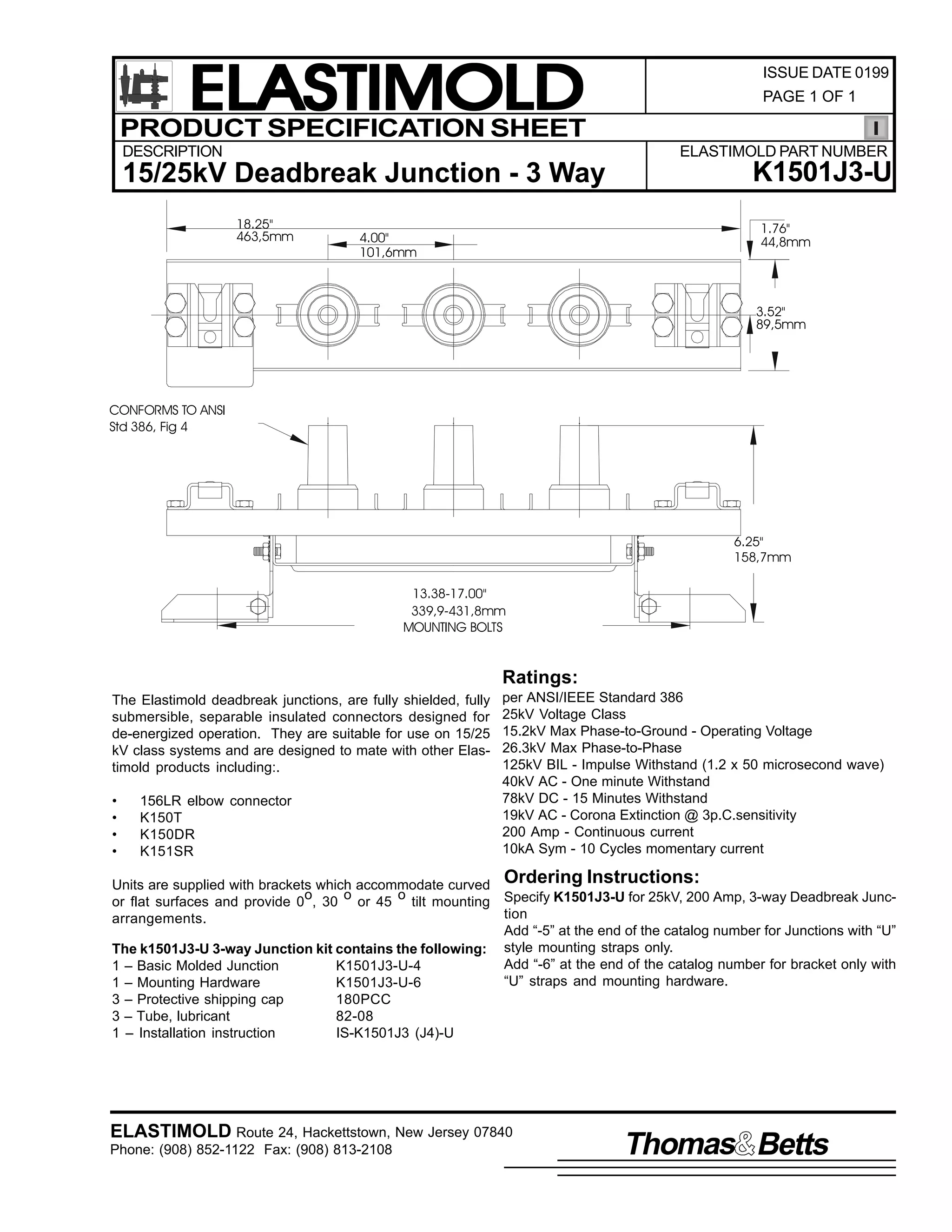
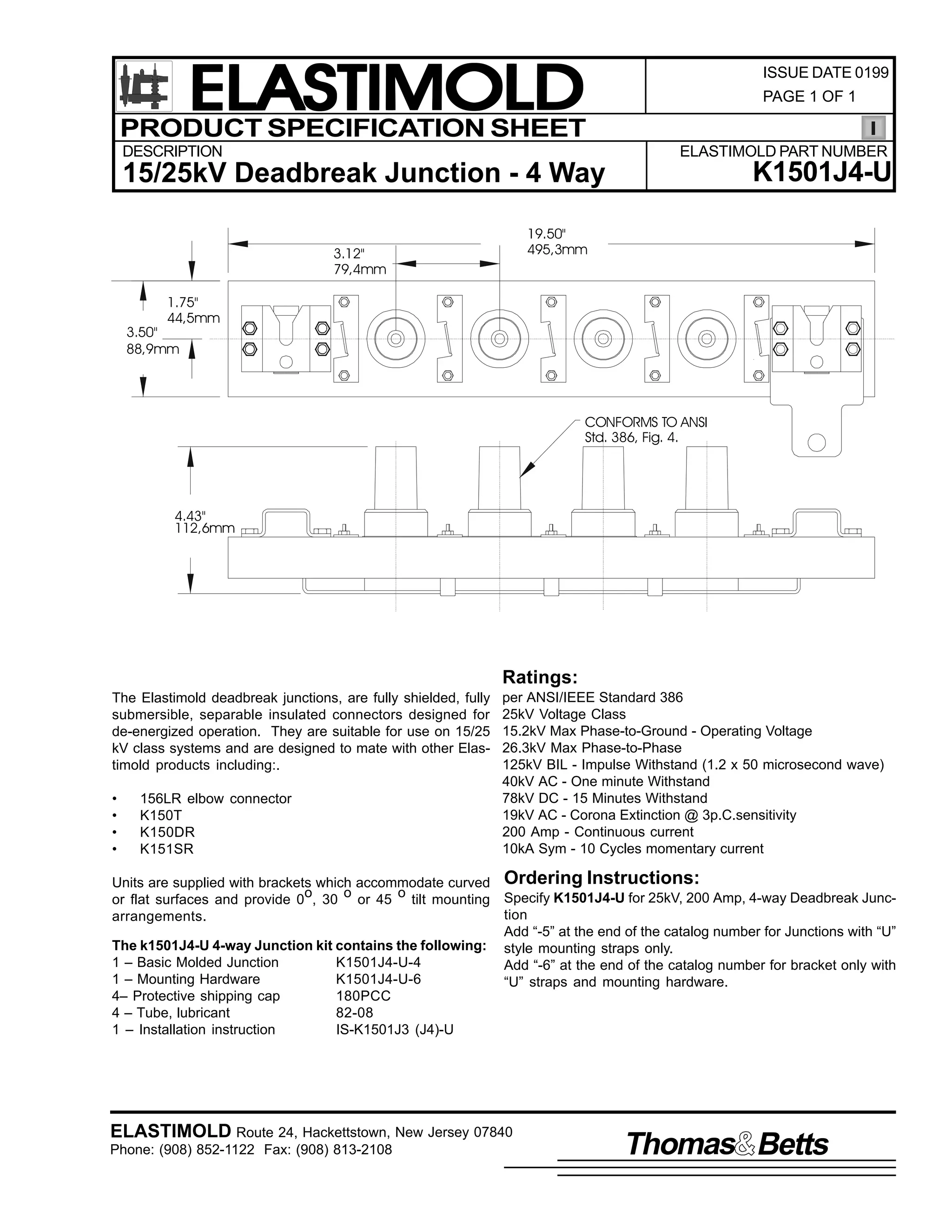
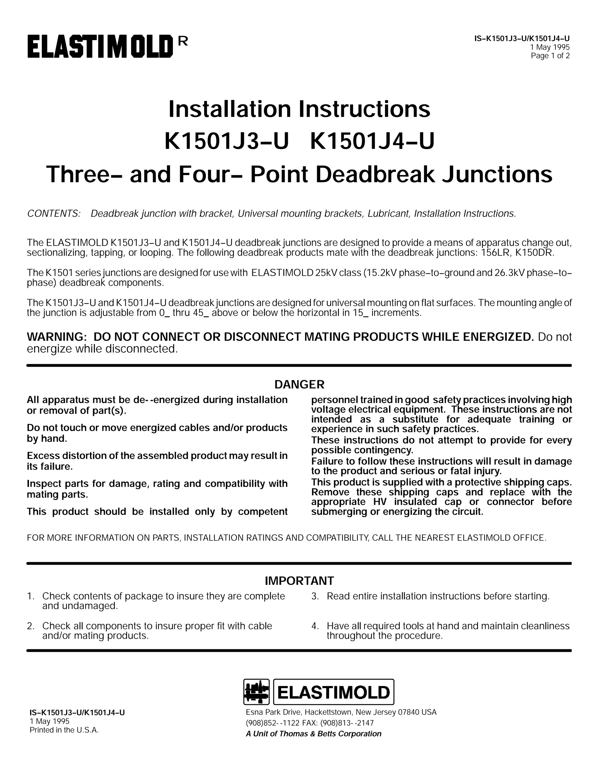
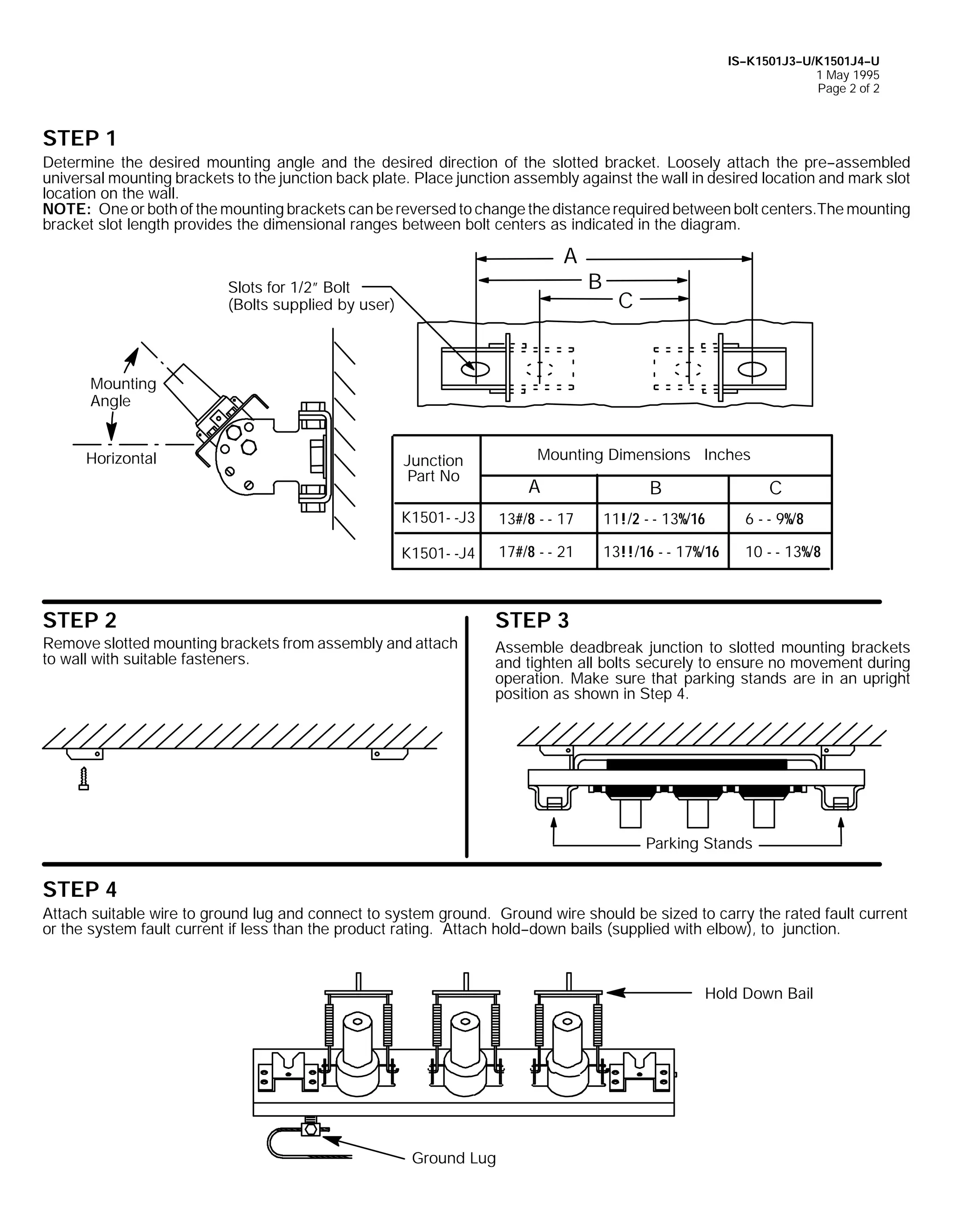
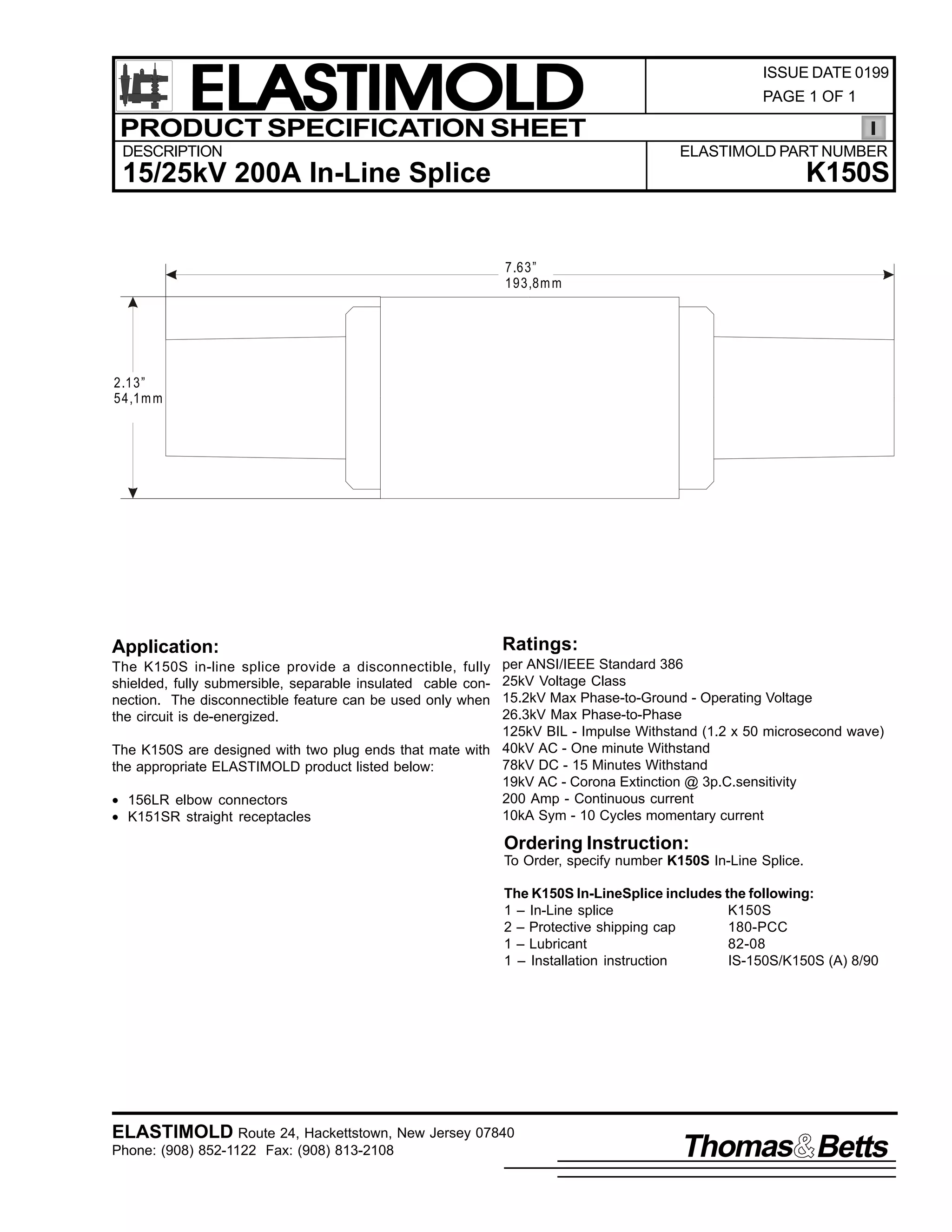
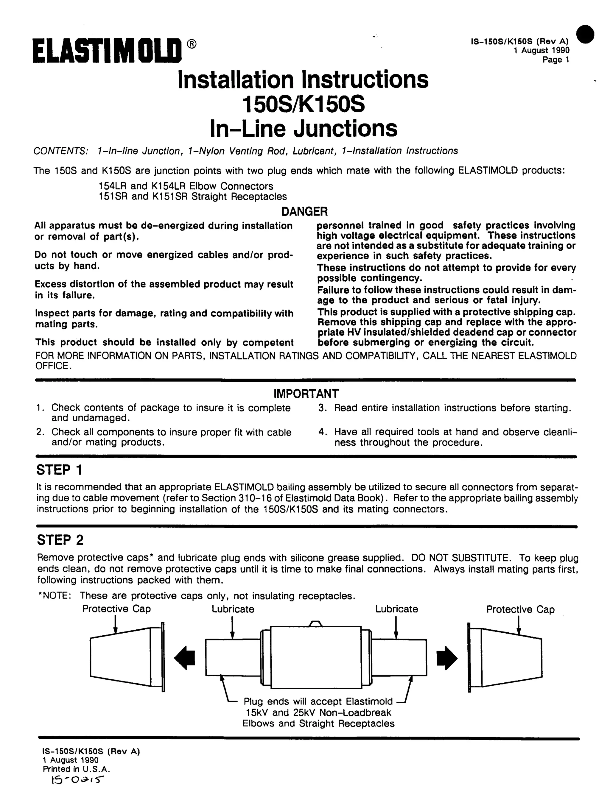
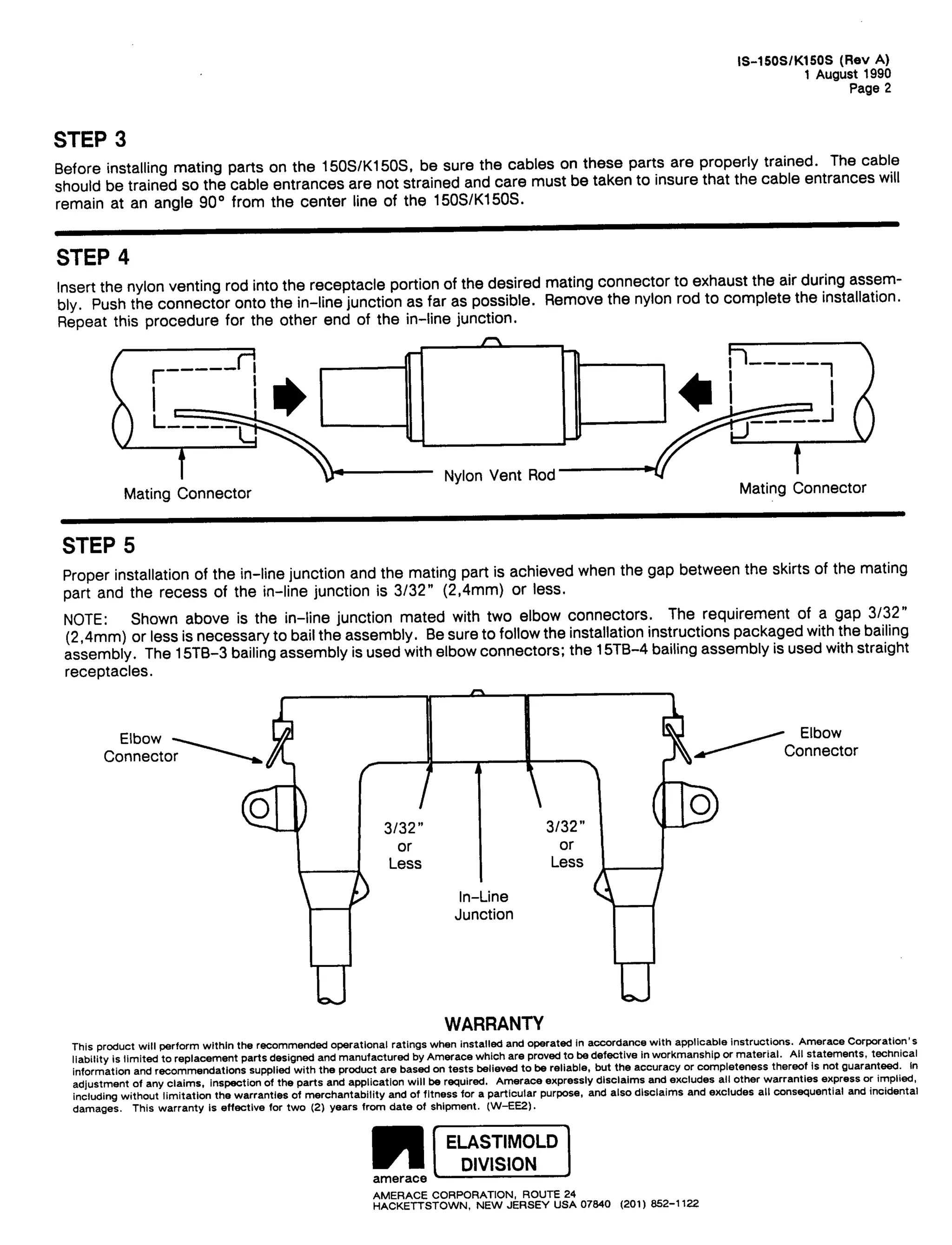
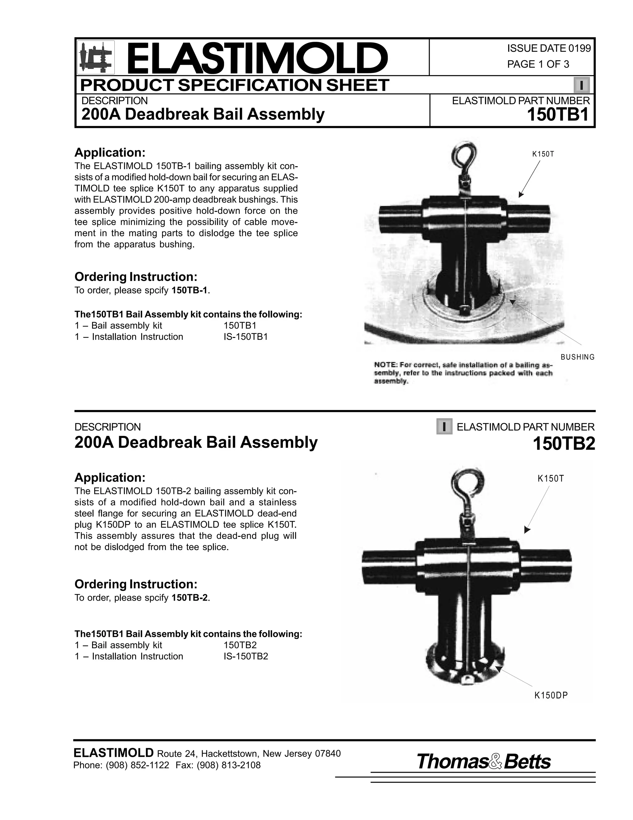
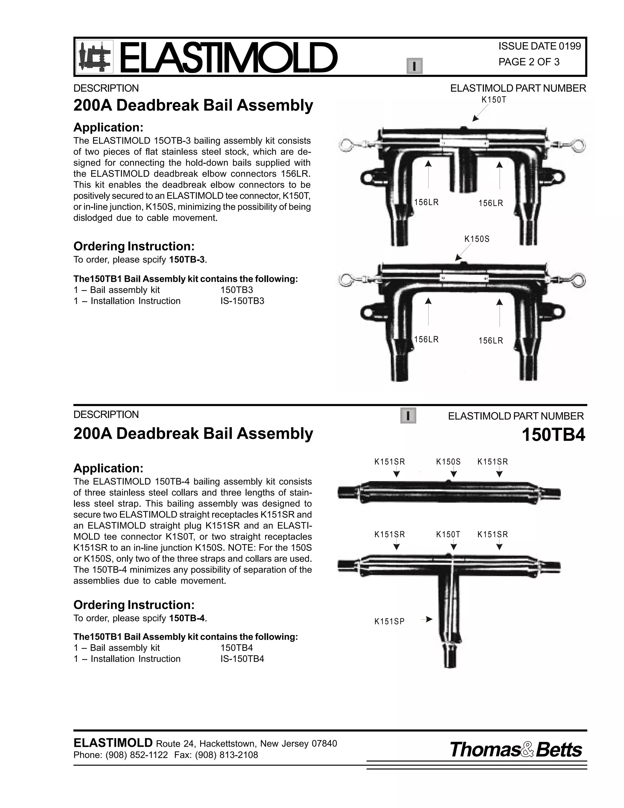
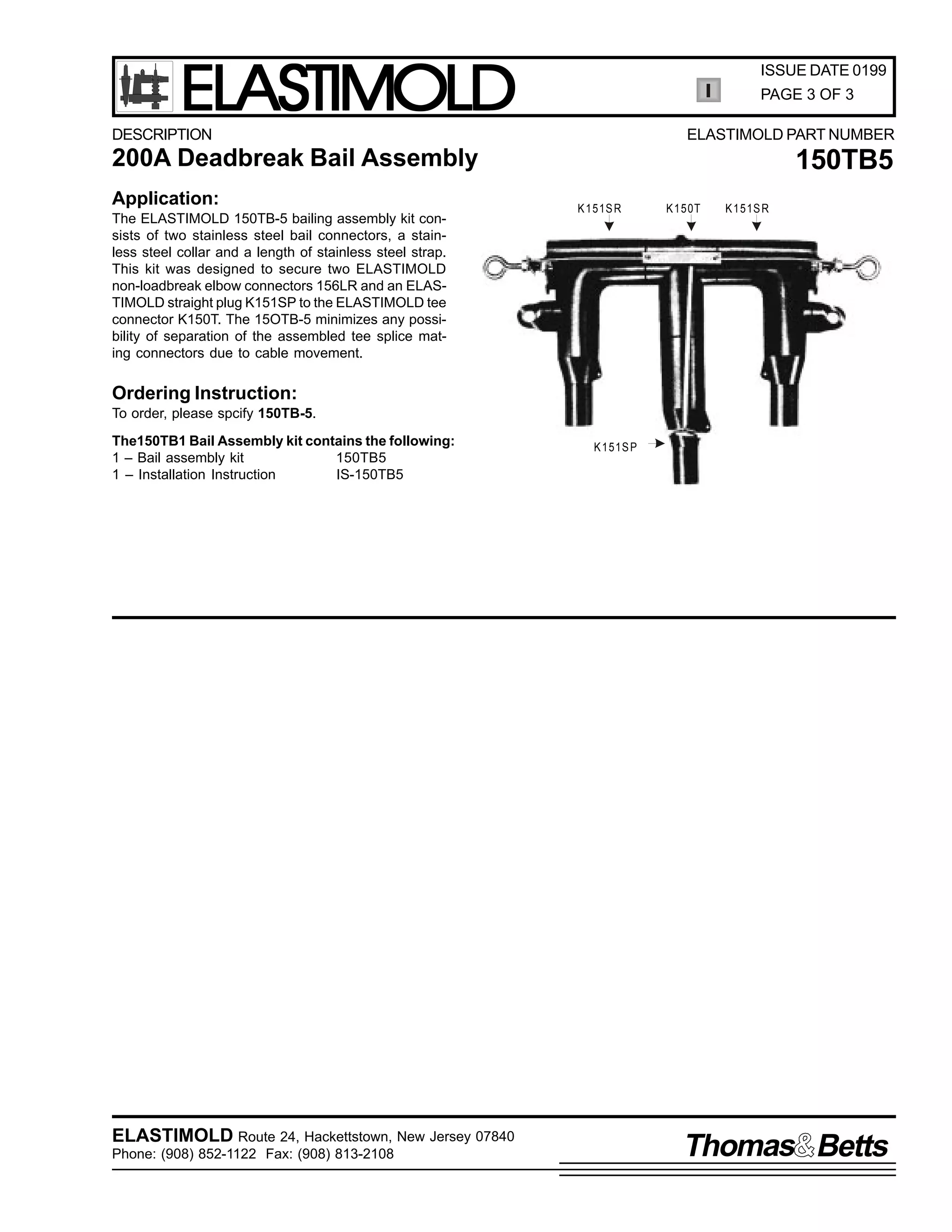
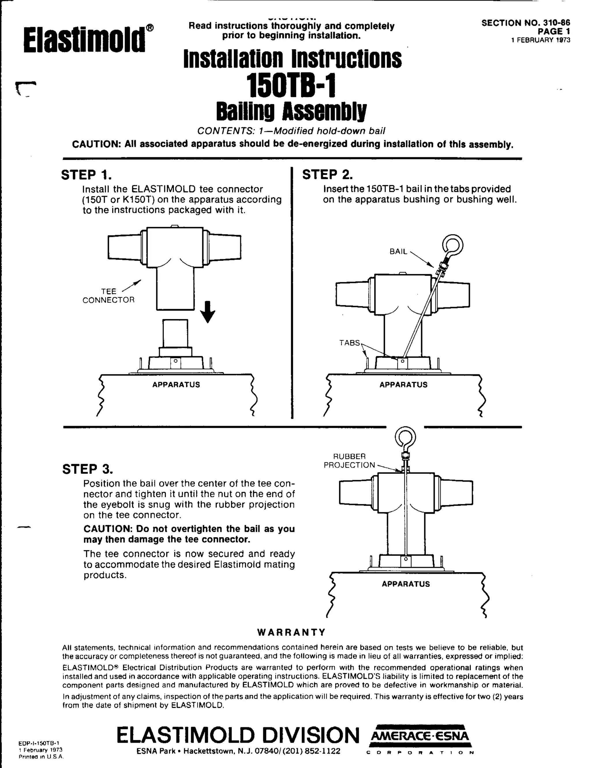
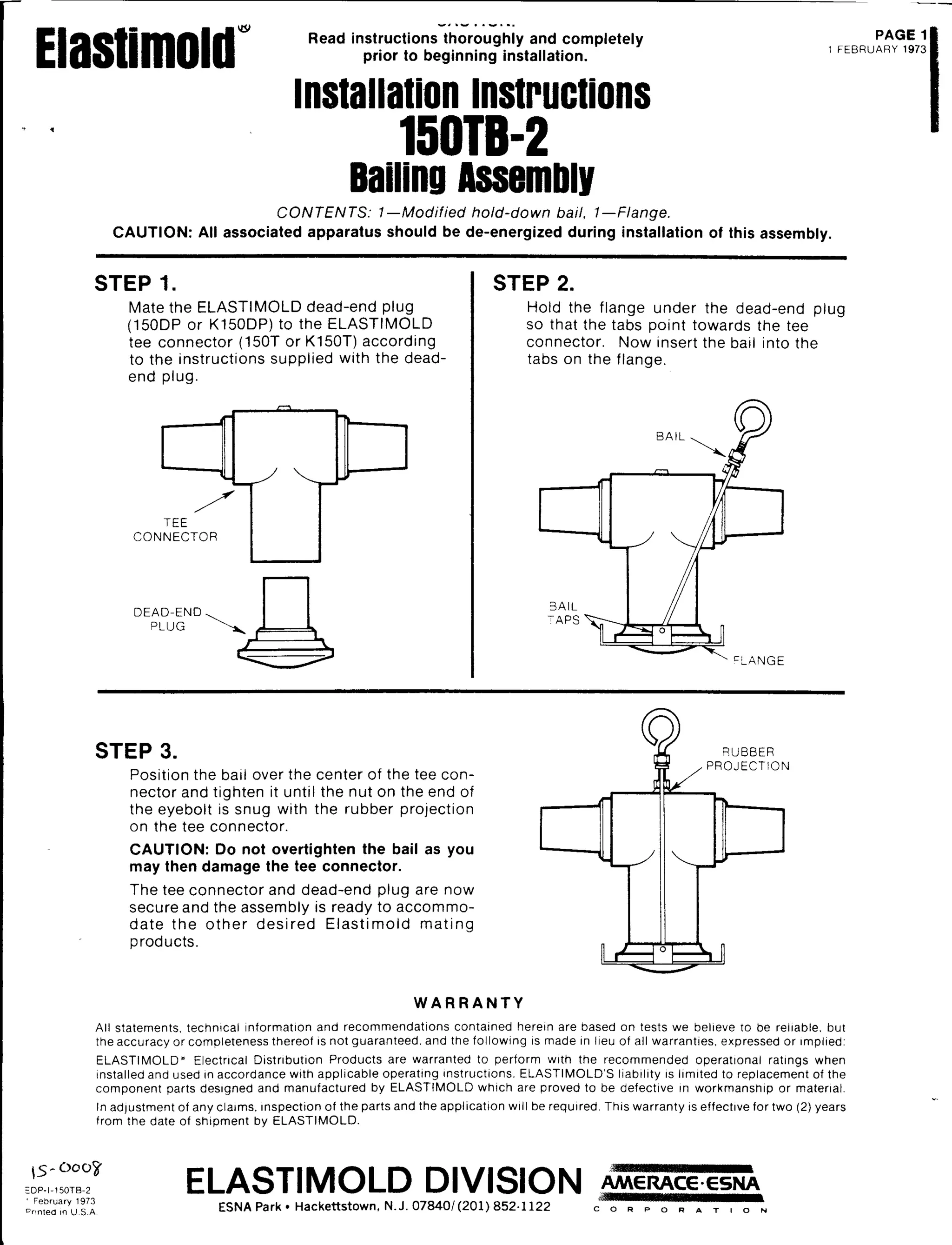
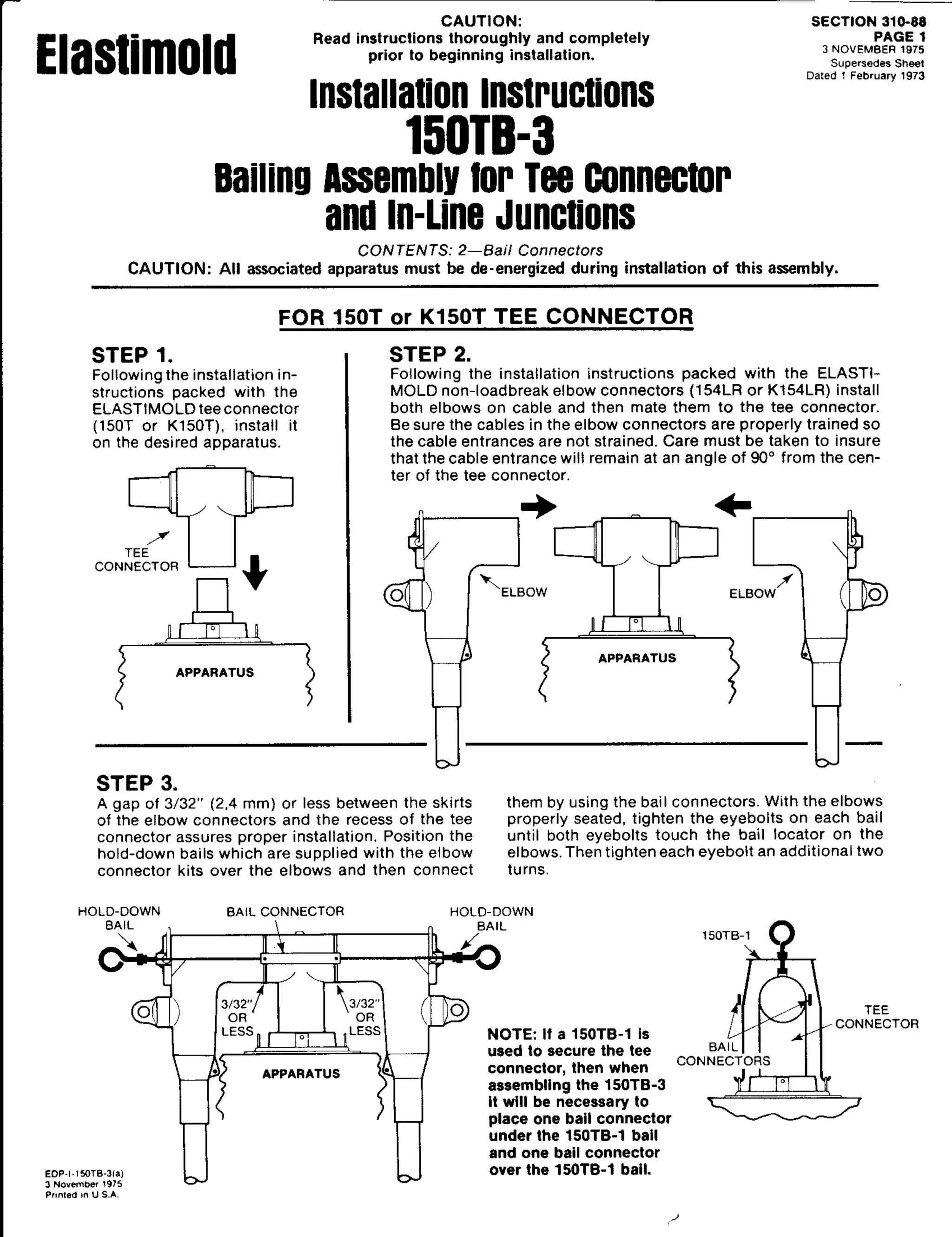
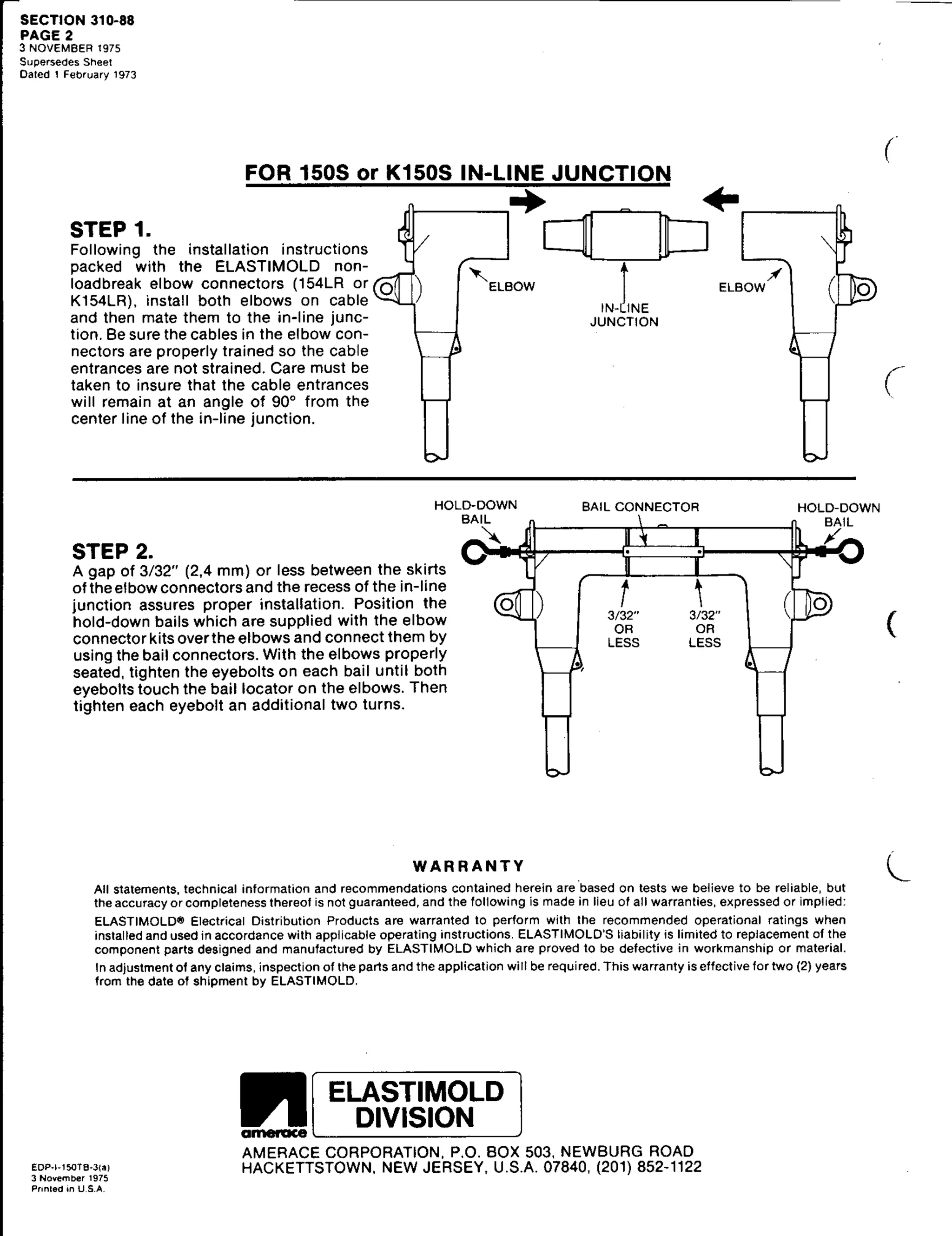
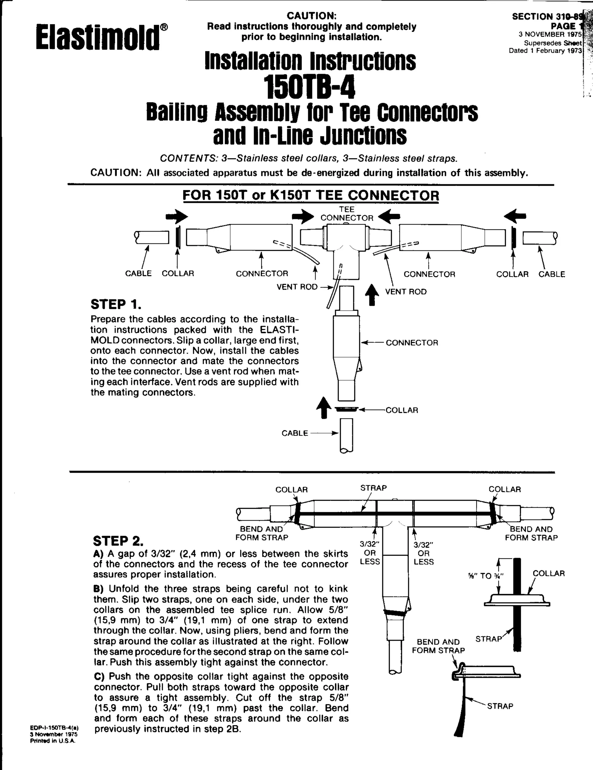
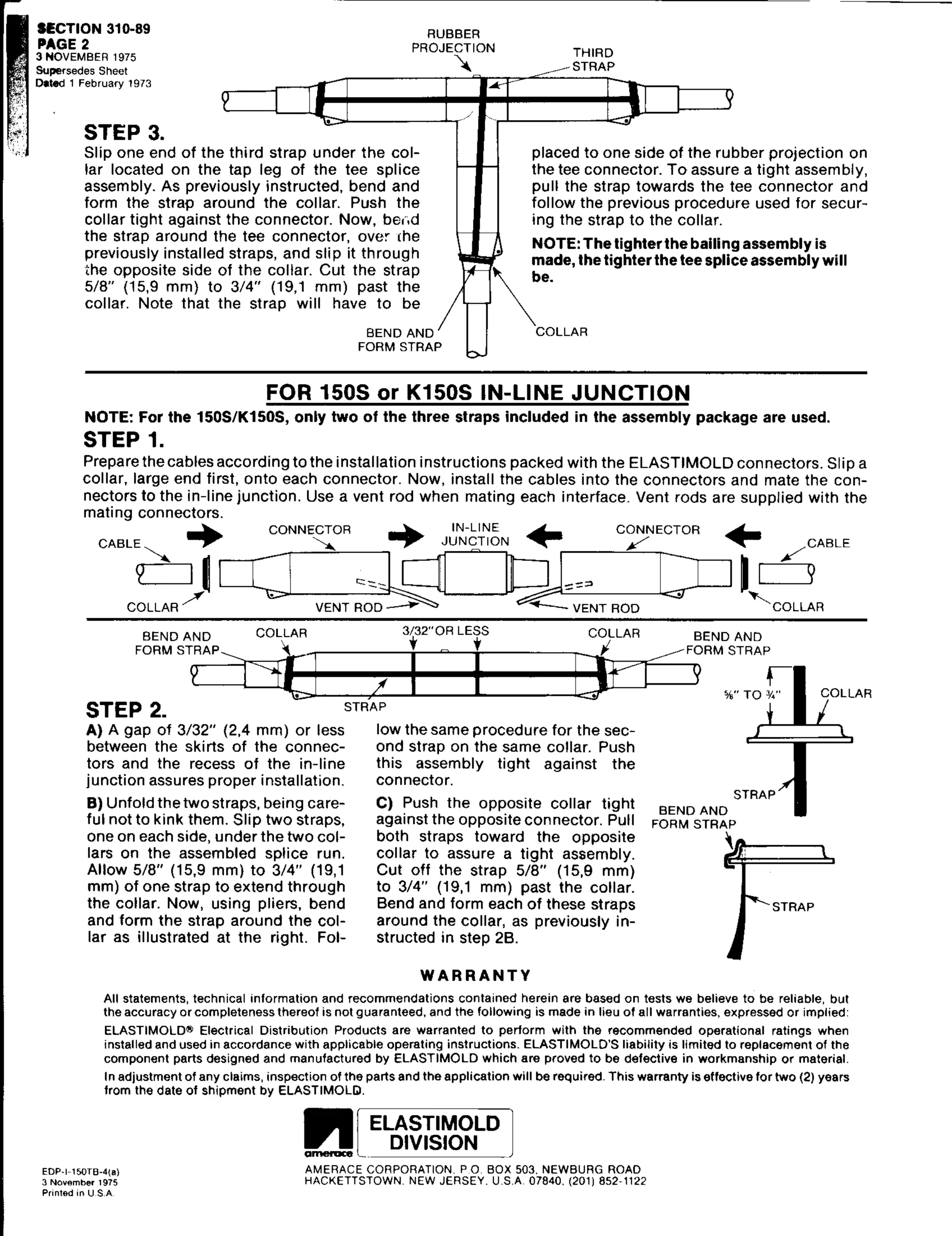
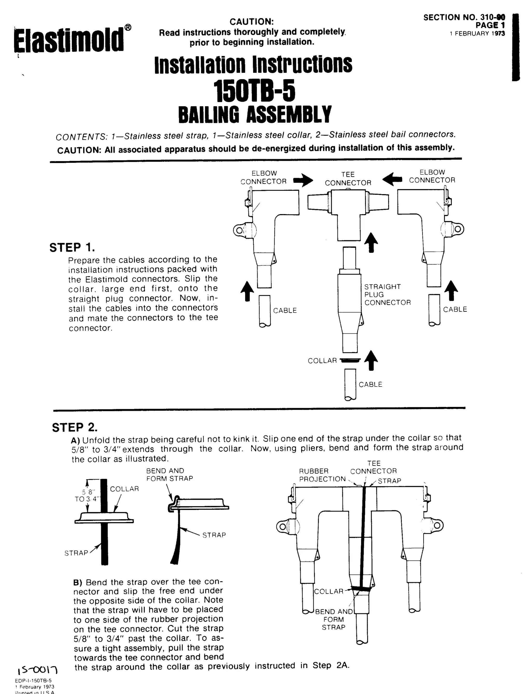
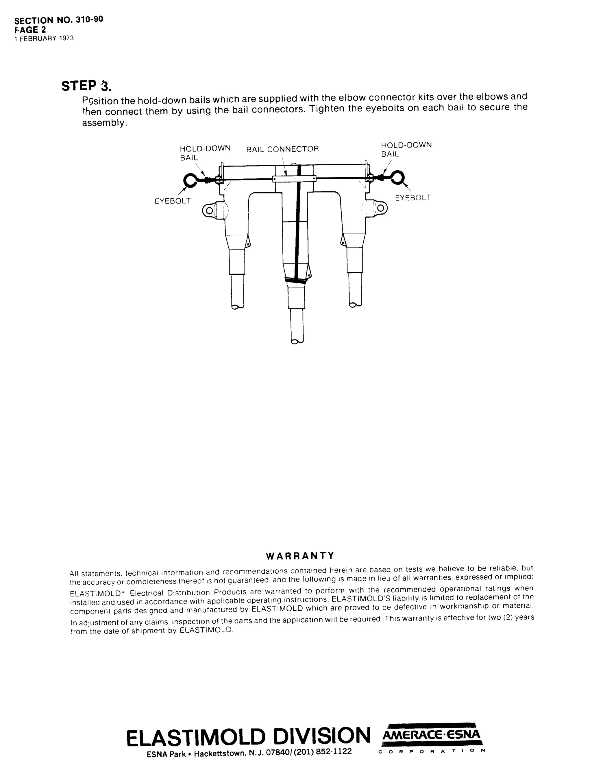
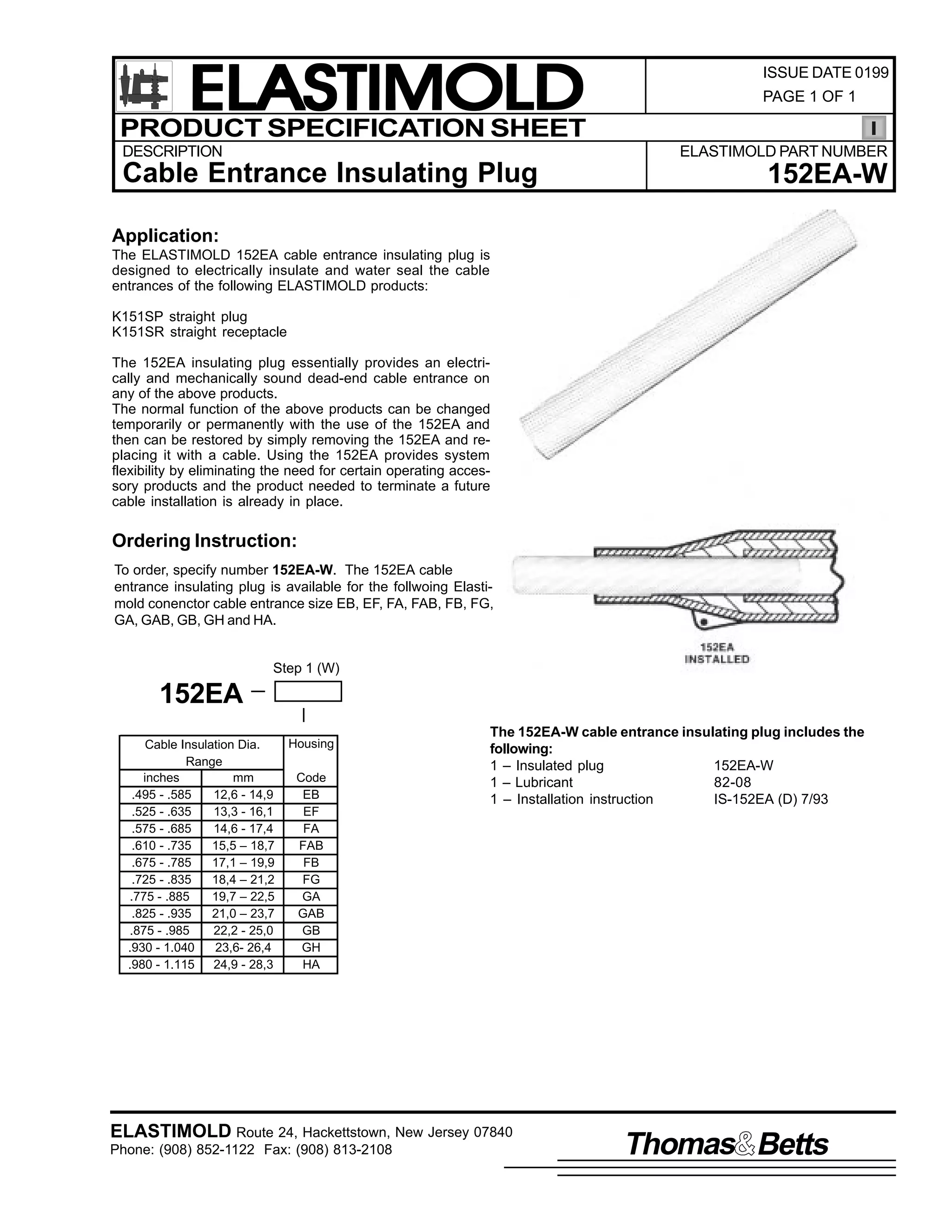
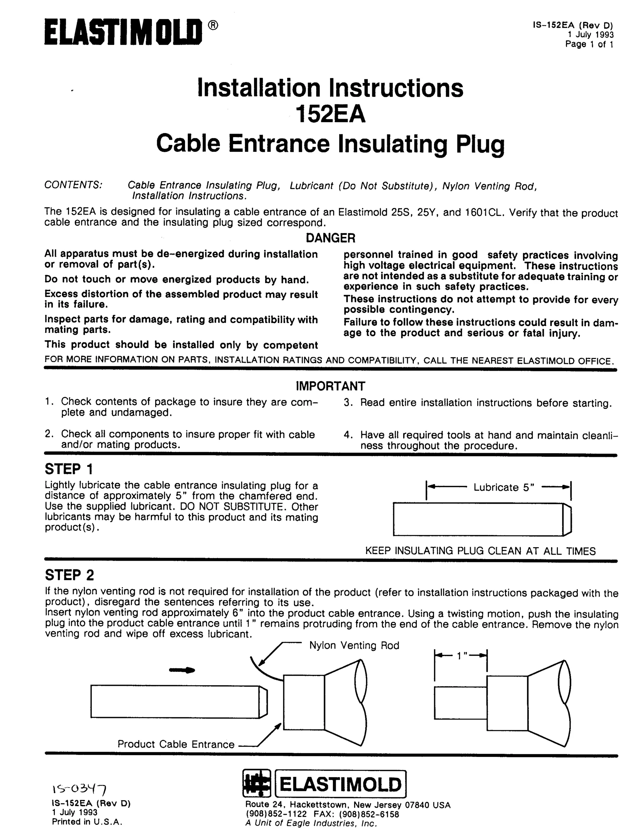
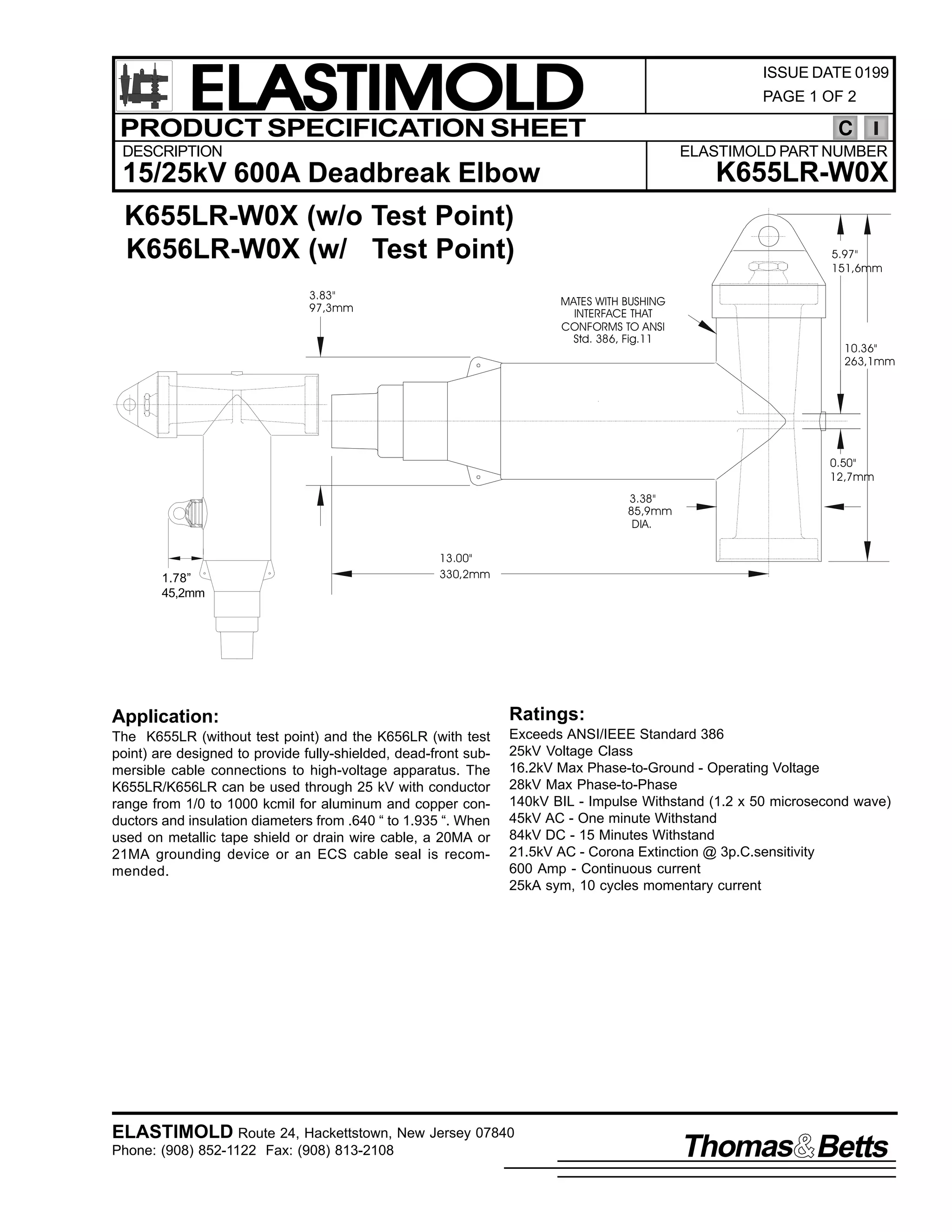
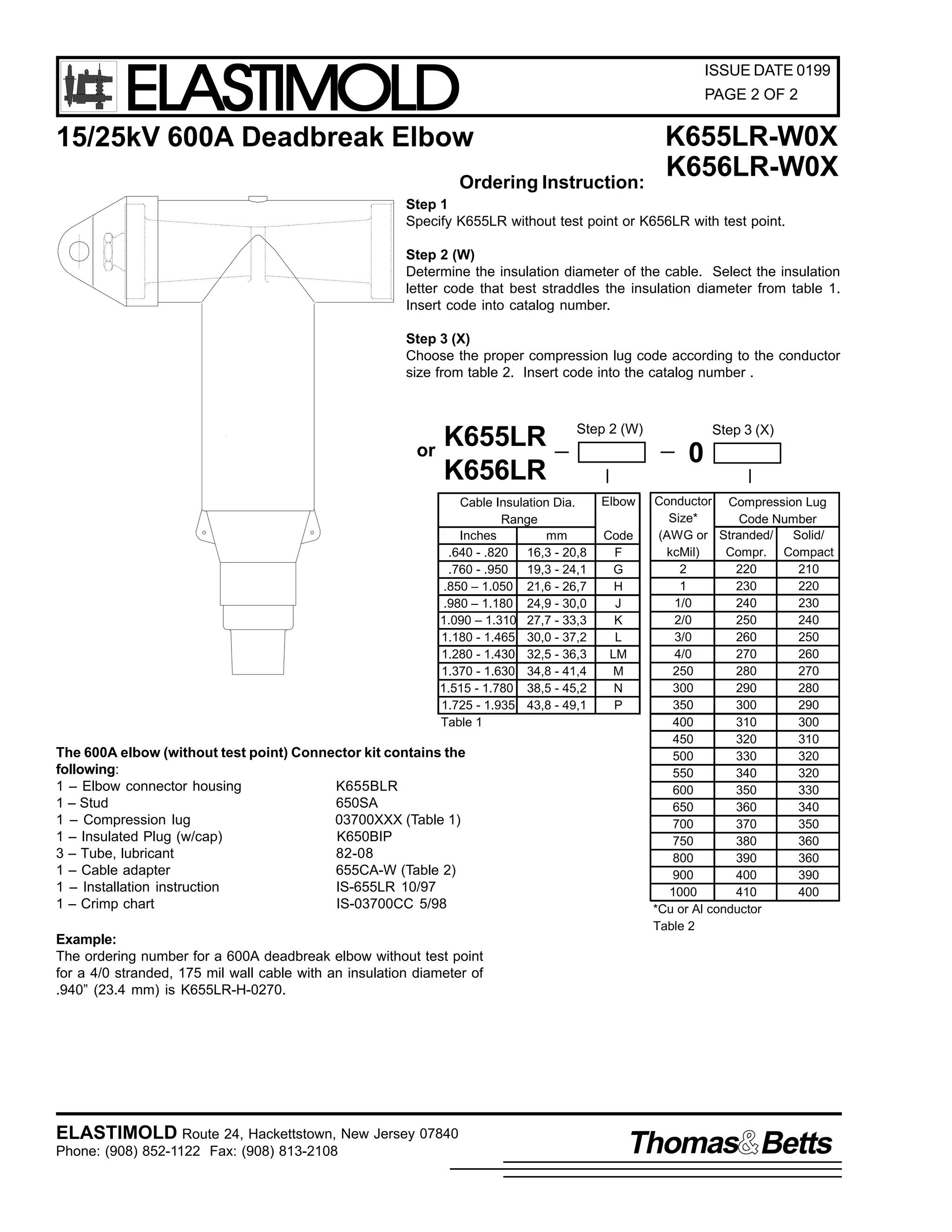
![9
&217(176=
,60 0988/5
2FWREHU 4<<:
3DJH 4 RI 7
,QVWDOODWLRQ ,QVWUXFWLRQV
98829:8/5 DQG .9882.9:8/5
(OERZ &RQQHFWRUV
(OERZ/ &DEOH $GDSWHU/ &RPSUHVVLRQ /XJ/ ,QVXODWLQJ 3OXJ/ /XEULFDQW/ 6WXG 3UHSDFN/ &ULPS FKDUW/
,QVWDOODWLRQ ,QVWUXFWLRQV1
7KH 98829:8/5 DQG .9882.9:8/5 FRQQHFWRUV DUH GHVLJQHG WR= 4, SURYLGH IXOO VKLHOGHG/ IXOO VXEPHUVLEOH GHDGIURQW FDEOH
FRQQHFWLRQV WR KLJK YROWDJH DSSDUDWXV DQG 5, SURYLGH D PHDQV WR VSOLFH DQG WDS 9330 0DPSHUH + 9882.988/5, RU
<330 0DPSHUH +9:82.9:8/5, VVWHPV1 7KH FRQQHFWRUV DUH UDWHG IRU XVH RQ 48N9 DQG 58N9 FODVV VVWHPV UHVSHFWLYHO1
'$1*(5
$OO DSSDUDWXV PXVW EH GH0 0HQHUJL]HG GXULQJ LQVWDOODWLRQ
RU UHPRYDO RI SDUW+V,1
'R QRW WRXFK RU PRYH HQHUJL]HG SURGXFWV E KDQG1
([FHVV GLVWRUWLRQ RI WKH DVVHPEOHG SURGXFW PD UHVXOW
LQ LWV IDLOXUH1
,QVSHFW SDUWV IRU GDPDJH/ UDWLQJ DQG FRPSDWLELOLW ZLWK
PDWLQJ SDUWV1
7KLV SURGXFW VKRXOG EH LQVWDOOHG RQO E FRPSHWHQW
SHUVRQQHO WUDLQHG LQ JRRG VDIHW SUDFWLFHV LQYROYLQJ
KLJK YROWDJH HOHFWULFDO HTXLSPHQW1 7KHVH LQVWUXFWLRQV
DUH QRW LQWHQGHG DV D VXEVWLWXWH IRU DGHTXDWH WUDLQLQJ RU
H[SHULHQFH LQ VXFK VDIHW SUDFWLFHV1
7KHVH LQVWUXFWLRQV GR QRW DWWHPSW WR SURYLGH IRU HYHU
SRVVLEOH FRQWLQJHQF1
)DLOXUH WR IROORZ WKHVH LQVWUXFWLRQV ZLOO UHVXOW LQ GDPDJH
WR WKH SURGXFW DQG VHULRXV RU IDWDO LQMXU1
7KLV SURGXFW LV VXSSOLHG ZLWK D SURWHFWLYH VKLSSLQJ
FRYHU1 5HPRYH WKLV VKLSSLQJ FRYHU DQG UHSODFH ZLWK WKH
DSSURSULDWH +9 LQVXODWHG FDS RU FRQQHFWRU EHIRUH
VXEPHUJLQJ RU HQHUJL]LQJ WKH FLUFXLW1
)25 025( ,1)250$7,21 21 3$576/ ,167$//$7,21 5$7,1*6 $1' &203$7,%,/,7</ &$// 7+( 1($5(67 (/$67,02/' 2)),&(1
,03257$17
41 &KHFN FRQWHQWV RI SDFNDJH WR LQVXUH WKH DUH FRPSOHWH
DQG XQGDPDJHG1
51 &KHFN DOO FRPSRQHQWV WR LQVXUH SURSHU ILW ZLWK FDEOH
DQG2RU PDWLQJ SURGXFWV1
61 5HDG HQWLUH LQVWDOODWLRQ LQVWUXFWLRQV EHIRUH VWDUWLQJ1
71 +DYH DOO UHTXLUHG WRROV DW KDQG DQG PDLQWDLQ FOHDQOLQHVV
WKURXJKRXW WKH SURFHGXUH1
*(1(5$/ ,16758&7,216
67(3 4
3RVLWLRQ WKH FDEOH VR LW LV ORFDWHG LQ WKH ILQDO DVVHPEOHG SRVLWLRQ ZLWK HQRXJK VODFN WR SURYLGH DGHTXDWH FOHDUDQFH IRU
UHPRYLQJ WKH HOERZV1 )RU FRQFHQWULF QHXWUDO FDEOH/ XQZLQG WKH FRQFHQWULF QHXWUDO ZLUHV1 &XW WKH FDEOH 40 0627l +78PP, IURP
FHQWHU OLQH RI WKH PDWLQJ SURGXFW1
40 0627l
+78PP,
&RQFHQWULF 1HXWUDO :LUHV
+:KHUH $SSOLFDEOH,
9330 0DPSHUH
0DWLQJ 3URGXFW
67(3 5
&OHDQ WKH RXWHU VXUIDFH RI WKH FDEOH D GLVWDQFH RI 57l +943PP, RU XS WR WKH EHQW EDFN FRQFHQWULF QHXWUDO ZLUHV1
,60 0988/5
2FWREHU 4<<:
3ULQWHG LQ 8161$1
(VQD 3DUN 'ULYH/ +DFNHWWVWRZQ/ 1HZ -HUVH 3:;73 86$
+<3;,;850 04455 )$;= +<3;,;460 0547:
$ 8QLW RI 7KRPDV ) %HWWV &RUSRUDWLRQ](https://image.slidesharecdn.com/elastimold-140130102426-phpapp02/75/Elastimold-Connectors-Loadbreak-Deadbreak-Elbow-Bolted-Tee-Connectors-HV-MV-700-Series-293-2048.jpg)
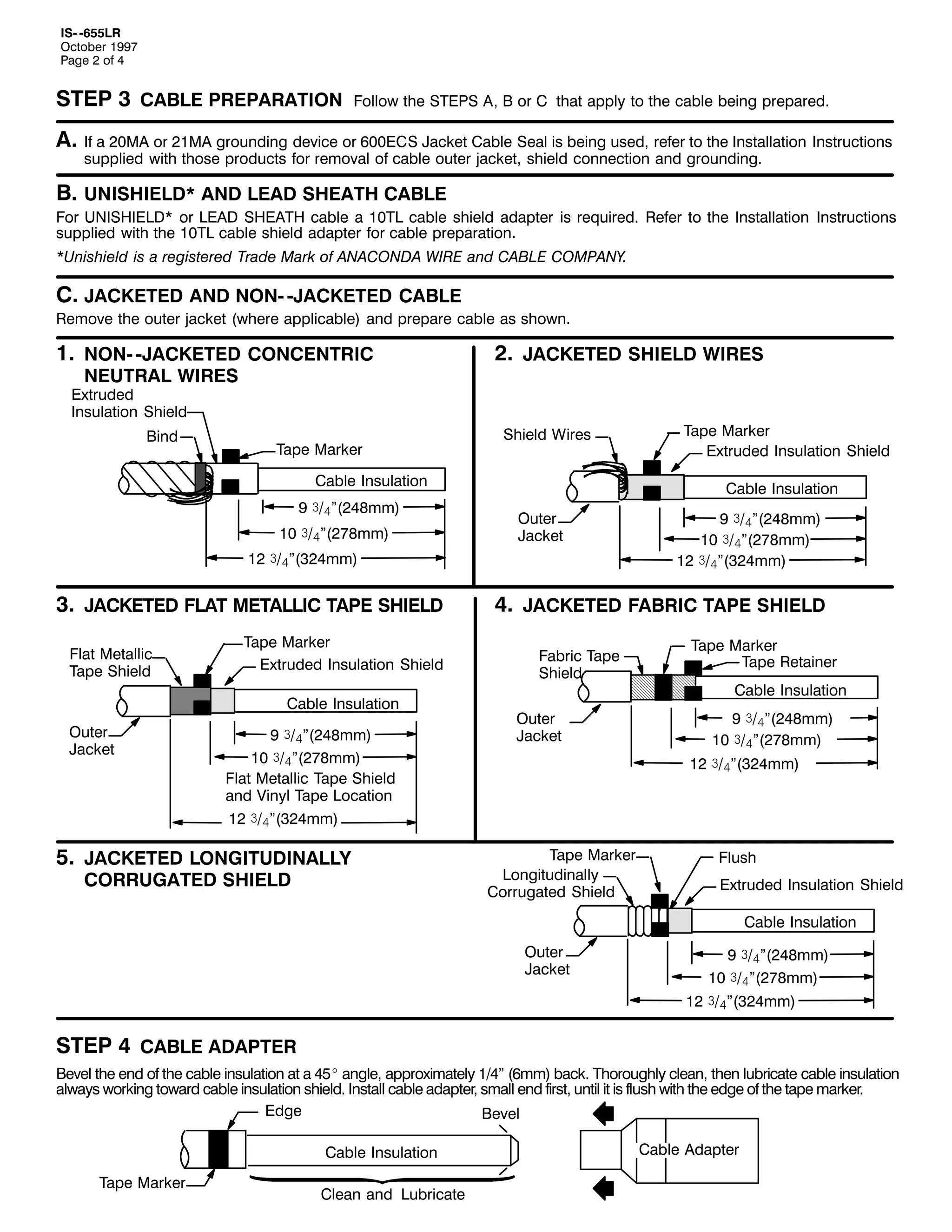
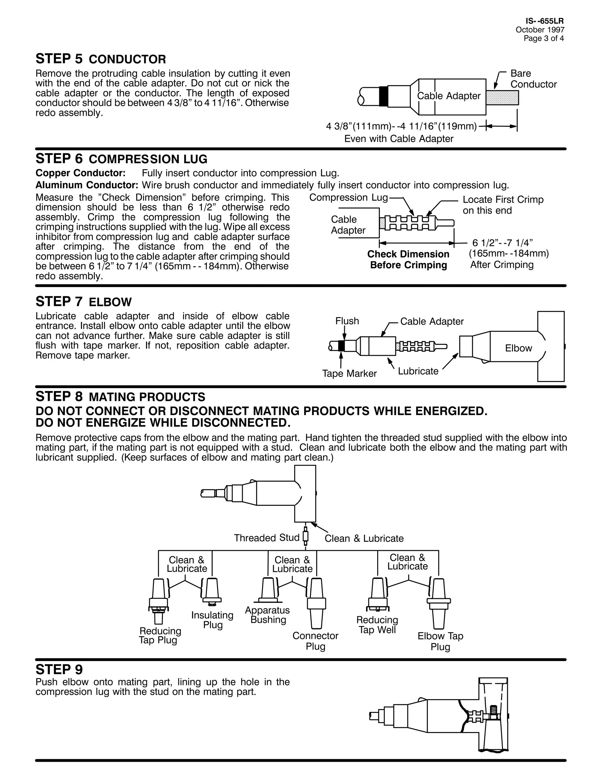
![,60 0988/5
2FWREHU 4<<:
3DJH 7 RI 7
67(3 43
&OHDQ DQG OXEULFDWH WKH PDWLQJ SDUW IRU WKH RSSRVLWH HQG RI
WKH HOERZ1 ,QVHUW WKH PDWLQJ SDUW LQWR WKH HOERZ1 (QJDJH
WKH WKUHDGV DQG KDQG WLJKWHQ1 7RUTXH PDWLQJ SDUW
DFFRUGLQJ WR WKH LQVWUXFWLRQV VXSSOLHG ZLWK WKH PDWLQJ SDUW1
(OERZ
7DS 3OXJ
&RQQHFWRU
3OXJ
&OHDQ
)
/XEULFDWH
5HGXFLQJ
7DS 3OXJ
%DVLF
,QVXODWLQJ
3OXJ
&OHDQ
)
/XEULFDWH
67(3 44
,I DQ LQVXODWLQJ SOXJ LV XVHG DV D PDWLQJ SDUW/ FOHDQ DQG
OXEULFDWH LQQHU VXUIDFH RI WKH YROWDJH GHWHFWLRQ FDS DQG
SODFH RQ HOERZ1 3XVK GRZQ KDUG XQWLO FDS VQDSV LQWR SODFH1
)ROORZ YROWDJH WHVW GLUHFWLRQV EHORZ1
5HGXFLQJ
7DS :HOO
&OHDQ
)
/XEULFDWH
&DSDFLWLYH 7HVW 3RLQW
&OHDQ )
/XEULFDWH
&OHDQ ) /XEULFDWH
67(3 45
,QVHUW RQH HQG RI D SLHFH RI ZLUH ZLWK DPSDFLW DW OHDVW
HTXLYDOHQW WR 1R1 47 $:* &RSSHU WKURXJK WKH JURXQGLQJ
HH DQG WZLVW WR PDNH D VPDOO ORRS1 'R 1RW GDPDJH WKH HH1
&RQQHFW ZLUH WR JURXQG XVLQJ D VXLWDEOH FRQQHFWRU1
7KH VKLHOG RI WKH FDEOH PXVW EH JURXQGHG1 *URXQG
DFFRUGLQJ WR WKH LQVWUXFWLRQV VXSSOLHG ZLWK WKH JURXQGLQJ
GHYLFH1 ,I QR JURXQGLQJ GHYLFH LV XVHG/ WKH VKLHOG PXVW EH
JURXQGHG WKURXJK DQ DOWHUQDWH PHWKRG1
,W LV DOVR UHFRPPHQGHG WKDW WKH MDFNHW RI WKH FDEOH EH
ZDWHUSURRIHG DW WKLV SRLQW WR SUHYHQW PRLVWXUH IURP
HQWHULQJ WKH FDEOH1
)URP *URXQGLQJ
'HYLFH RU &DEOH 6KLHOG
7R *URXQG
*URXQG (H
&RQQHFWLRQ :LUH
67(3 46
&$87,21= :KHQ FRQVWUXFWLQJ 933DPS /0 0.LWV EH VXUH WR WLJKWHQ HDFK FRPSRQHQW WR VSHFLILHG WRUTXH SHU LQVWUXFWLRQV SURYLGHG1
92/7$*( 7(67
7KH (/$67,02/' HOERZ FRQQHFWRU LV HTXLSSHG ZLWK D LQWHJUDO FDSDFLWDQFH WHVW SRLQW WKDW FDQ EH XVHG WR HVWDEOLVK ZKHWKHU RU QRW WKH FLUFXLW LV HQHUJL]HG1 :KHQ
XVLQJ WKH WHVW SRLQW/ FRPSOHWH WKH IROORZLQJ VWHSV=
41
51
61
5HPRYH WHVW SRLQW FDS ZLWK D KRWVWLFN1 :KHQ UHPRYLQJ FDS/ 3((/ 2)) $7 $1 $1*/( UDWKHU WKDQ SXOOLQJ GLUHFWO LQ OLQH ZLWK WKH WHVW SRLQW DVVHPEO1
&$87,21= 7KH YROWDJH WHVW SRLQW LV D FDSDFLWDQFH GHYLFH> LW LV QRW GLUHFWO FRQQHFWHG WR WKH FRQQHFWRU1 ,W UHTXLUHV WKH XVH RI VSHFLDOO GHVLJQHG
LQVWUXPHQWV1 '2 127 86( &219(17,21$/ 92/7$*( 0($685,1* (48,30(17>12 ,1',&$7,21 :,// %( 2%7$,1('1
8VLQJ D VXLWDEOH VHQVLQJ GHYLFH/ SURFHHG WR GHWHUPLQH LI FDEOH LV HQHUJL]HG1 '2 127 86( &219(17,21$/ 92/7$*( 0($685,1* (48,30(171
:$51,1*= 7+( 92/7$*( 7(67 32,17 ,6 $ &$3$&,7$1&( '(9,&(/ ,7 ,6 127 ',5(&7/< &211(&7(' 72 7+(
&21'8&7251 &217$0,1$7,21= 02,6785(/ ',57/ (7&1/ $5281' 7+( 7(67 32,17/ 25 86( 2) 7+( :521*
0($685,1* (48,30(17 &$1 3529,'( $ )$/6( ´12 92/7$*(µ ,1',&$7,21 21 $1 (1(5*,=(' (/%2:1
72 35(9(17 6(5,286 25 )$7$/ ,1-85< 75($7 7+( (/%2: $6 (1(5*,=(' 817,/ 7+( ´12 92/7$*(µ
7(67 32,17 ,1',&$7,21 ,6 &21),50(' %< 27+(5 0($161
$IWHU YROWDJH GHWHFWLRQ KDV EHHQ PDGH/ FOHDQ DQG OXEULFDWH WKH LQVLGH VXUIDFH RI WKH FDS ZLWK VLOLFRQH JUHDVH DQG UHSODFH LW RQ WKH WHVW SRLQW1](https://image.slidesharecdn.com/elastimold-140130102426-phpapp02/75/Elastimold-Connectors-Loadbreak-Deadbreak-Elbow-Bolted-Tee-Connectors-HV-MV-700-Series-296-2048.jpg)
![9
,60036:33&&
0D 4<<;
3DJH 4 RI 4
&5,03,1* 722/6 ) ',(6 5(&200(1'(' )25 (/$67,02/'
933$03 &2035(66,21 &211(&7256
(/$67,02/'
6PERO
36:33;;;
&RQQHFWRU
21'1
&RQGXFWRU 6L]H
$OXPLQXP RU &RSSHU
6WUDQGHG
&RQFHQWULF
&RPSDFW 6ROLG
5RXQG
%XUQG
7)%
45 ) 48
7RQ
87+
73 7RQ
87
'LH
,QGH[
7RRO
<68
'LHV
.HDUQH
7RRO
<78/'LHV
7RRO
<7;%
'LHV
&6$
8576
+5,
8%*
+6,
85:57
+6,
5<;
85;$57
+6,
85;$57
+6,
&5;$5
+5,
864$57
+5,
8:38
+5,
8987
+5,
864$57
+5,
8:38
+5,
8987
+5,
7RRO
+0058
'LHV
<249
+6,
8:5
+5,
55+5,
;73
+7,
;73
+7,
57
'LH
1R1
&64$5
+4,
&:38
+5,
&987
+4,
867$57
+7,
7RRO
+005
'LHV
<249
+6,
8:5
+5,
576
%*
47
8576
+5,
8%*
+6,
85:57
+6,
7RRO
+004
'LHV
867$57
+7,
4;3
1958l
9
8
8
4<3
1;83l
8
7
7
533
1;83l
7
6
6
553
1;83l
5
4
4
563
1;83l
4
423
423
573
1;83l
423
523
523
583
1;83l
523
623
623
593
1;83l
623
723
723
5:3
1;83l
723
583
5;3
41485l
583
633
5<3
41485l
633
683
633
41485l
683
733
643
41653l
733
7832833
653
41653l
783
8332883
663
41653l
833
933
633
673
41653l
883
983
0
683
41653l
933
:33
693
41653l
983
:832;33
6;3
41953l
:332:83
<33
6<3
41953l
;33
<33
733
41;73l
<33
4333
41;73l
4333
753
41;73l
41;73l
51583l
4833
99+
99
5<<
<7+
<7
:38
987
439+
439
463
80
+5,
80
+5,
&67$5
+5,
93;
66<$57
+9,---
&6<$5
+5,
&93;
+5,
635
677$57
+9,---
&77$5
+5,
65<5
+9,---
&5<5
634
400ï7ä!
+6,
400ï7ä!
+6,
400ó7ã
+5,
65
400ñ7á
+5,
67
4583
7:3 --
:4
4433
773
:4+
743
-
4;:
8 'LHV UHTXLUH DGDSWHU 1R198481
--
483
)RU :83%/5 RQO1
7:;
+,
--- 1RWH= &HUWDLQ FDEOH FRQVWUXFWLRQV PD FDXVH H[FHVVLYH
FRQGXFWRU2FRQQHFWRU JURZWK/ FKHFN LQVWDOODWLRQ LQVWUXFWLRQV
IRU PD[1 FKHFN GLPHQVLRQ1 ,I JURZWK LV H[FHVVLYH UHGXFH WKH
QXPEHU RI FULPSV WR 7 PLQ1
,60036:33&&
0D 4<<;
3ULQWHG LQ 8161$1
5<5
&79$5+5,
500ó7á+5,
1XPEHU RI FULPSV +0LQLPXP, ZLWKRXW RYHUODSSLQJ1
5RWDWH HDFK VXFFHVVLYH FULPS <3E RU 4;3E WR SUHYHQW H[FHVVLYH
GLVWRUWLRQ1
:LUH EUXVK EDUHG DOXPLQXP FRQGXFWRU EHIRUHLQVHUWLQJ LQWRFRQGXFWRU
FRQWDFW1
(VQD 3DUN 'ULYH/ +DFNHWWVWRZQ/ 1HZ -HUVH 3:;73 86$
+<3;,;85004455 )$;= +<3;,;4600547:
$ 8QLW RI 7KRPDV ) %HWWV &RUSRUDWLRQ](https://image.slidesharecdn.com/elastimold-140130102426-phpapp02/75/Elastimold-Connectors-Loadbreak-Deadbreak-Elbow-Bolted-Tee-Connectors-HV-MV-700-Series-297-2048.jpg)
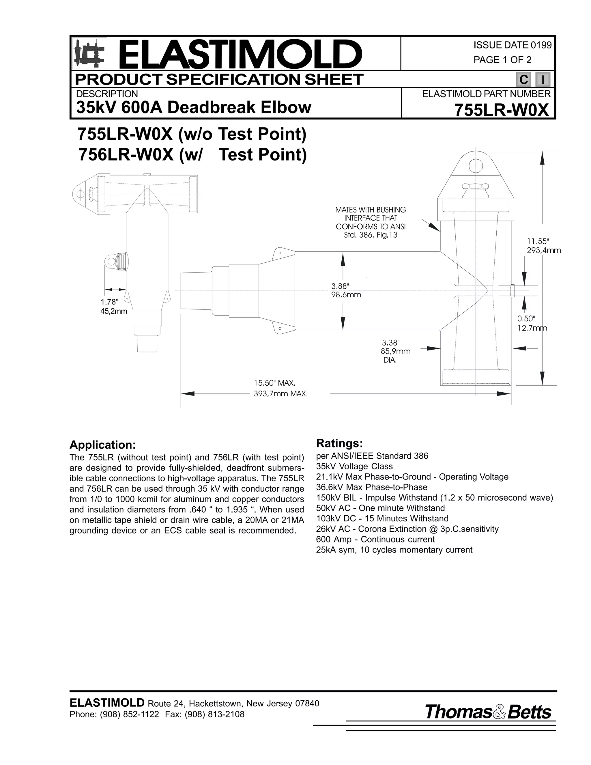
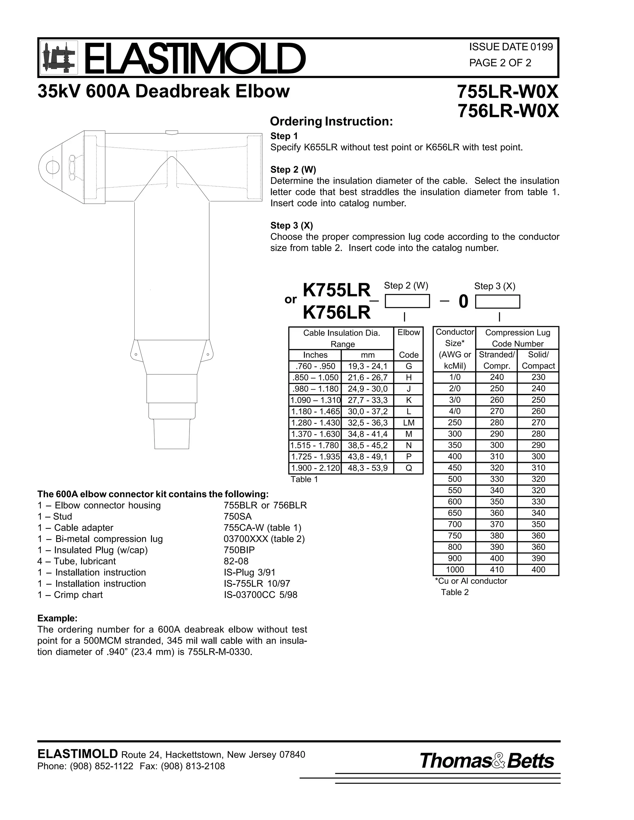
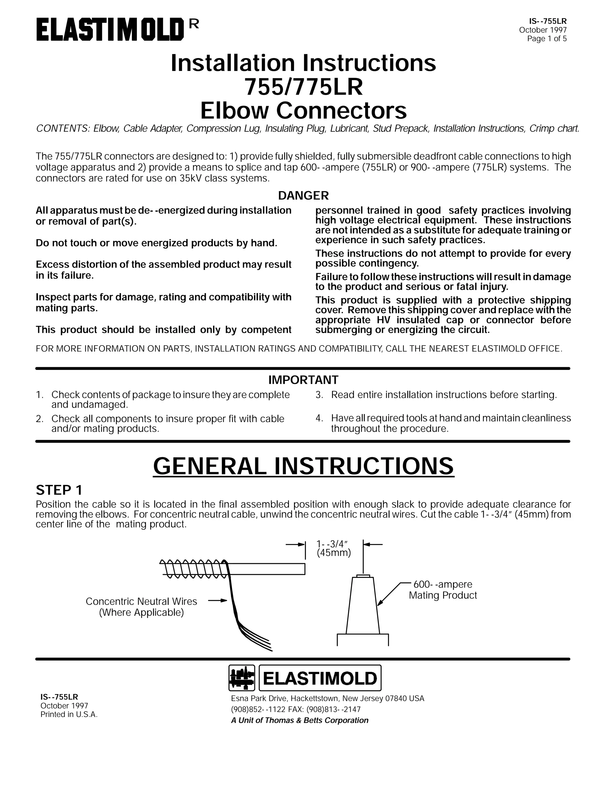
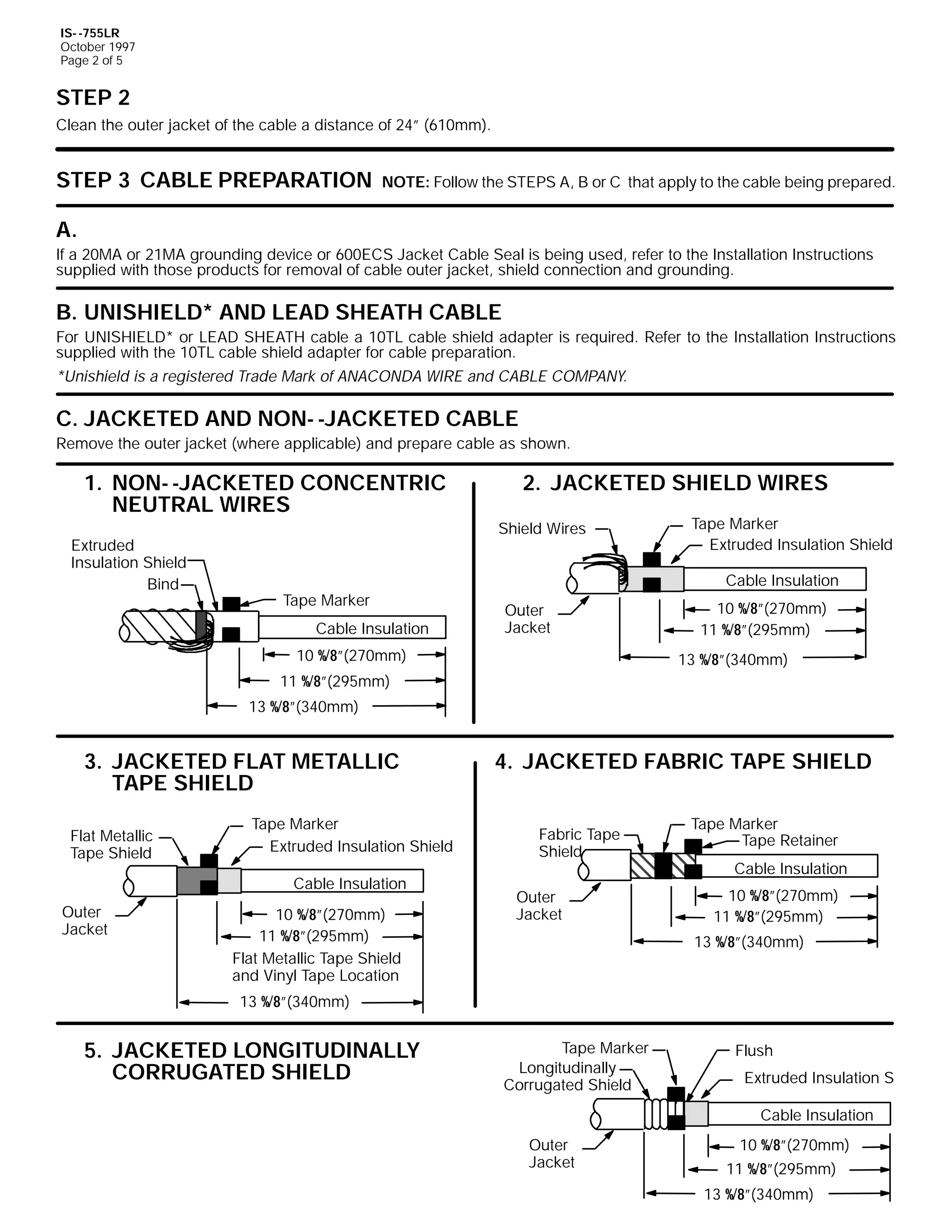
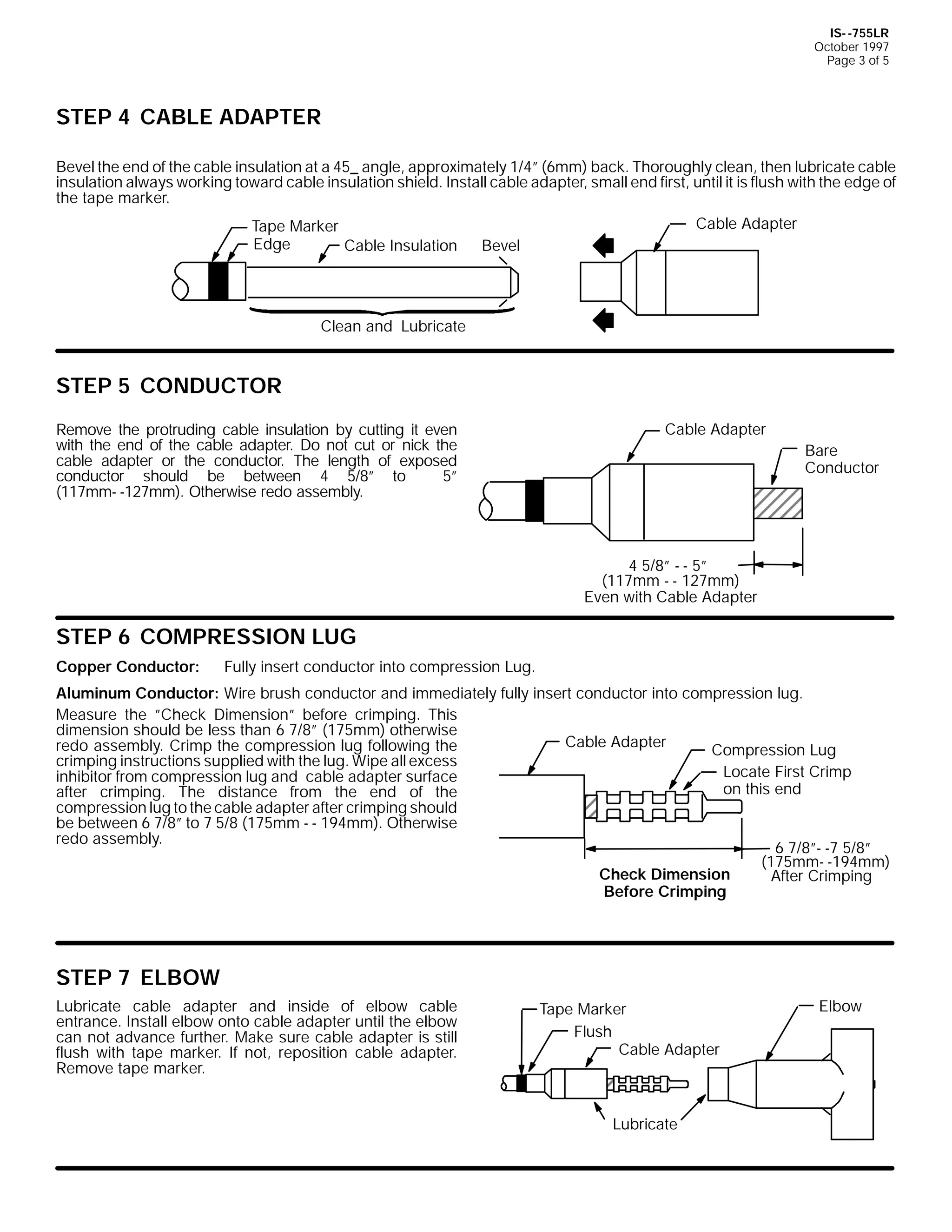
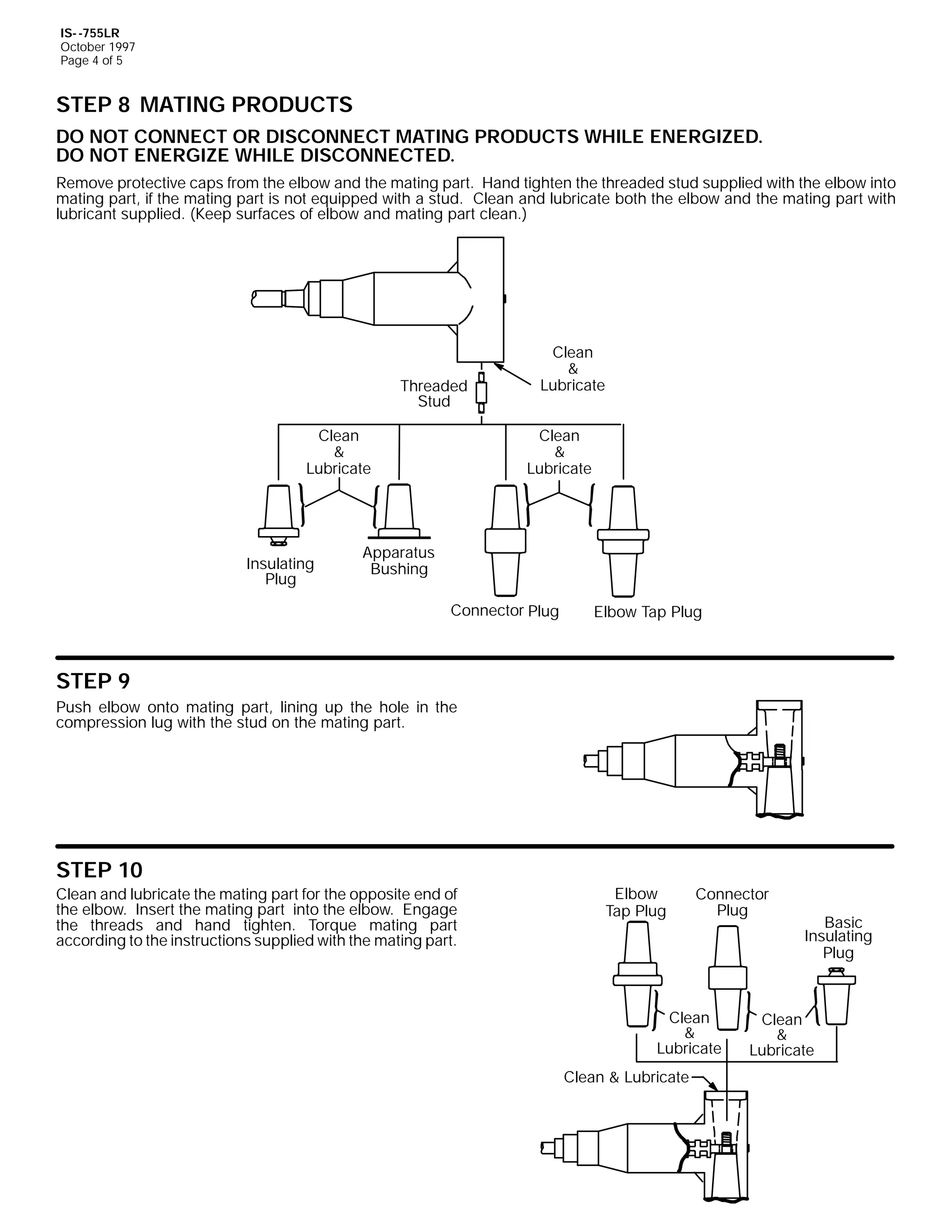
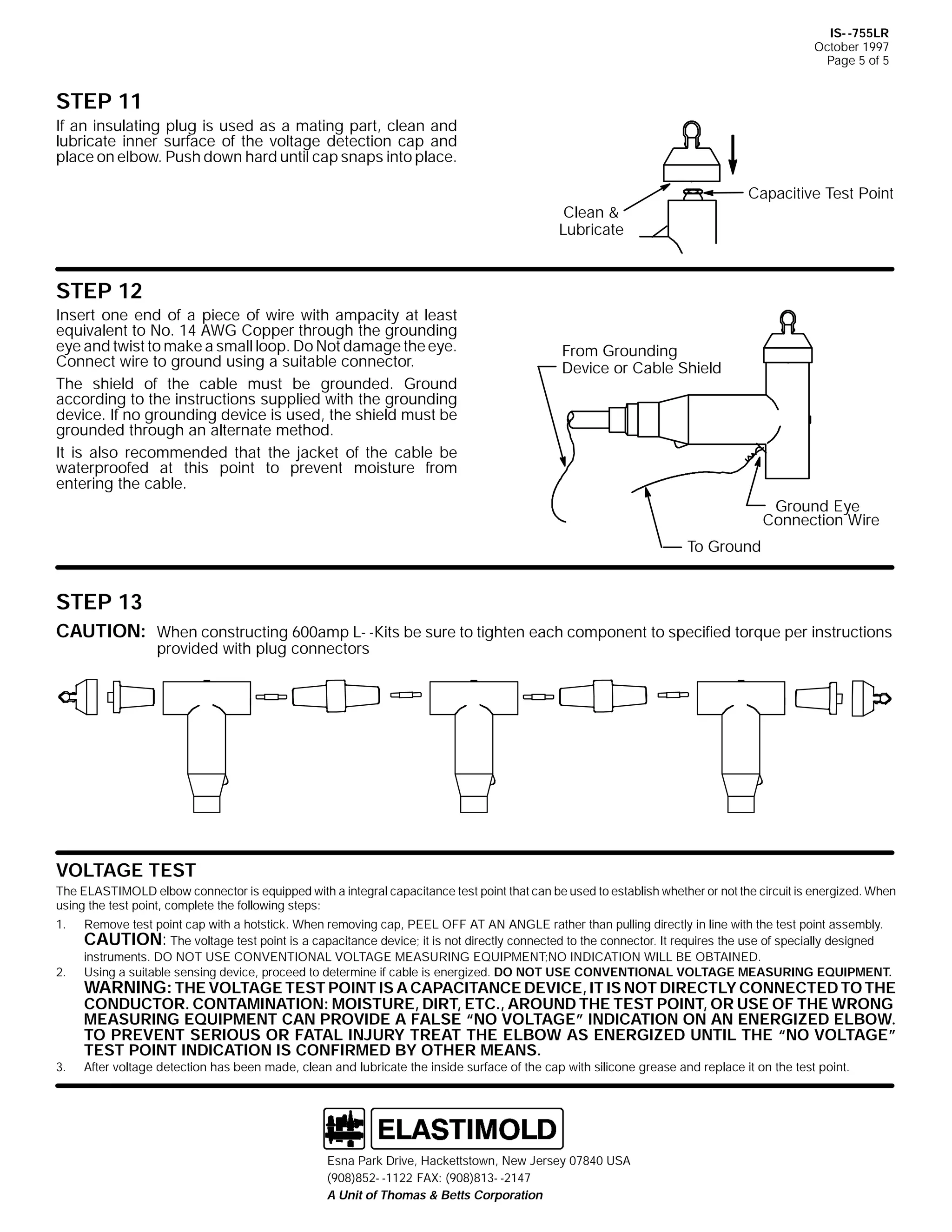
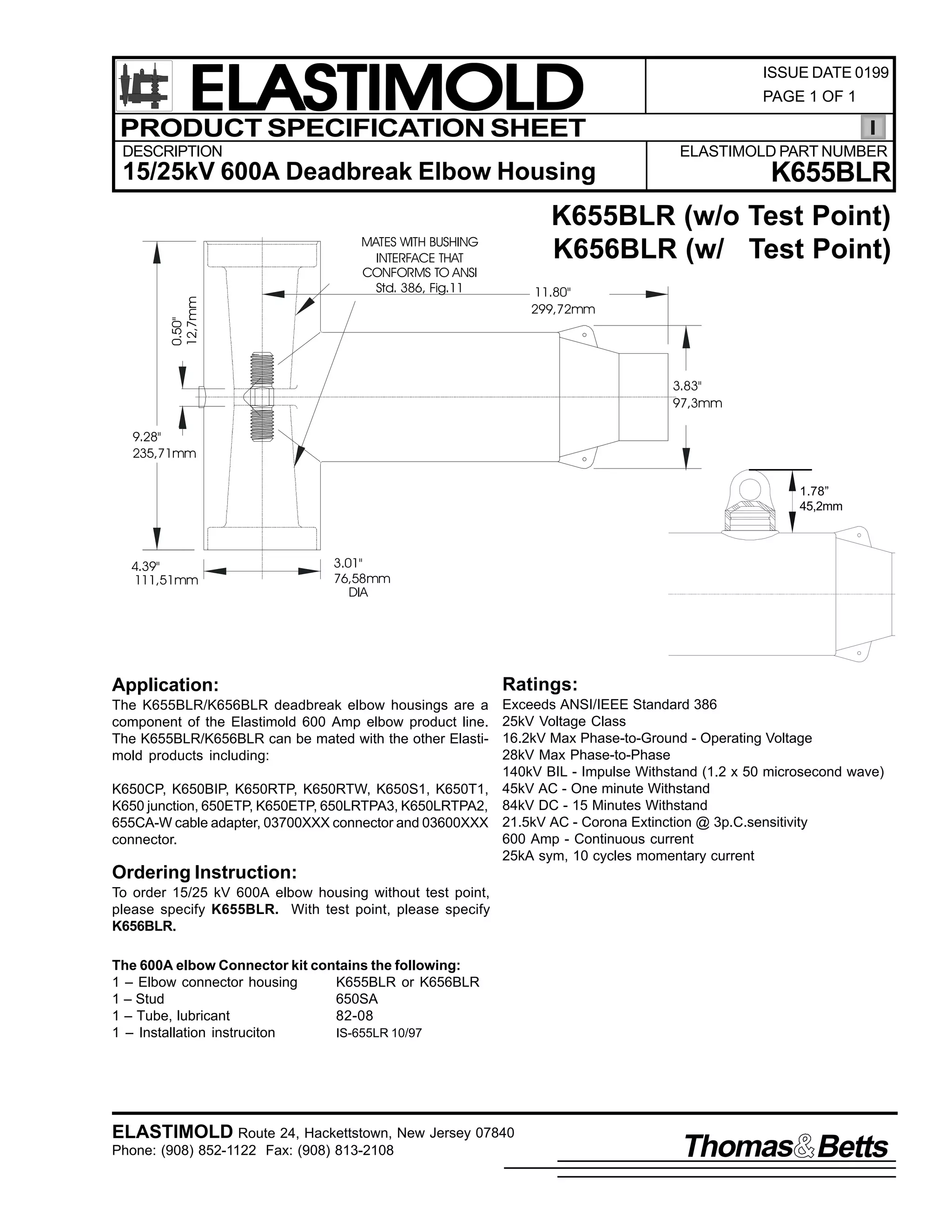
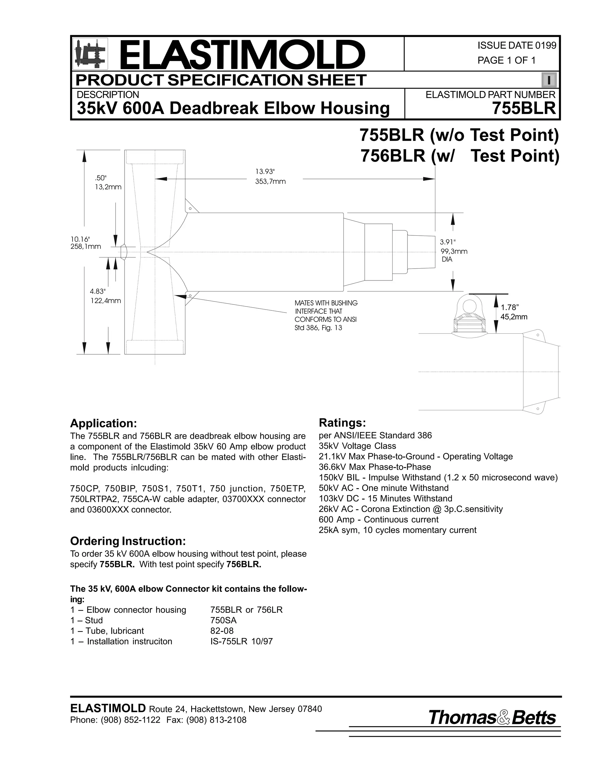

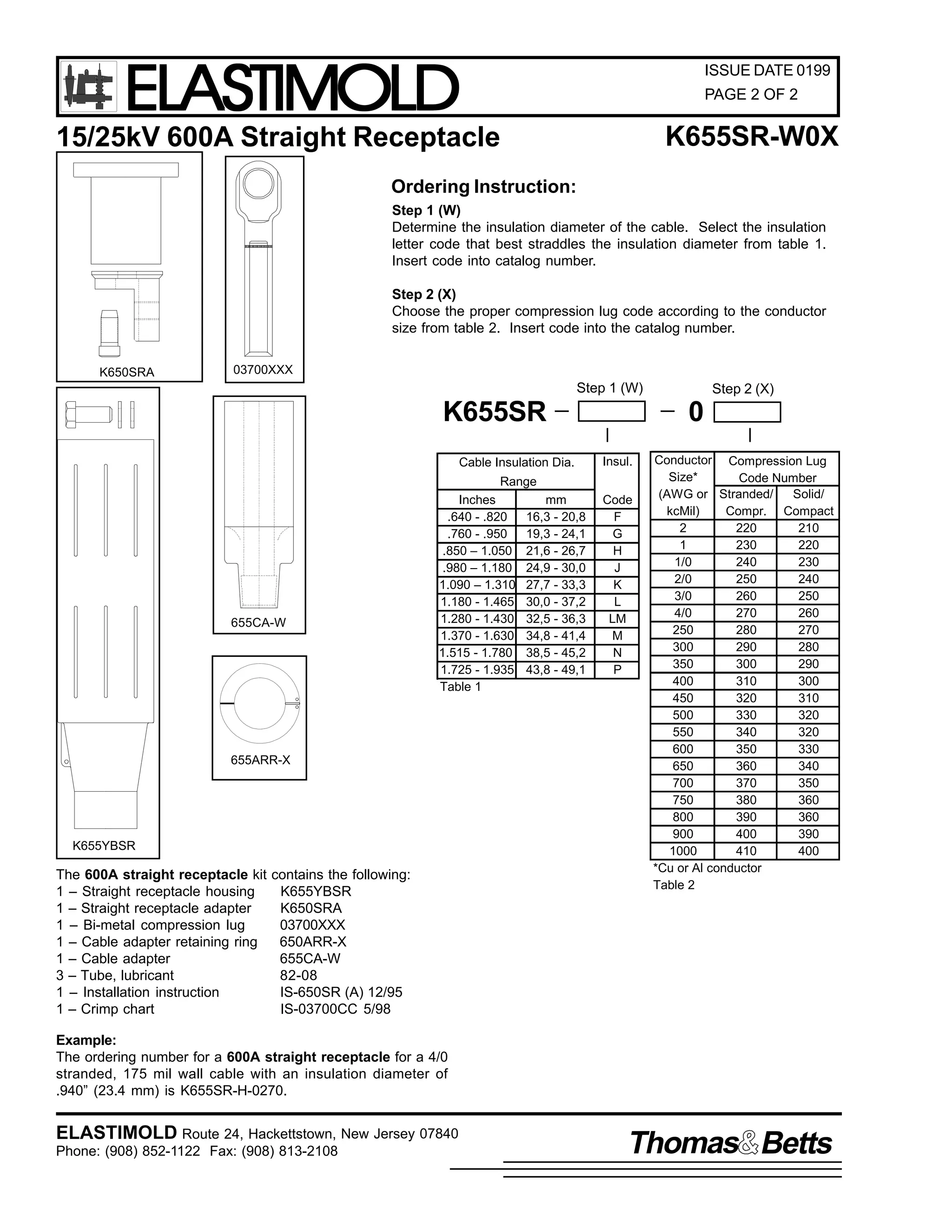
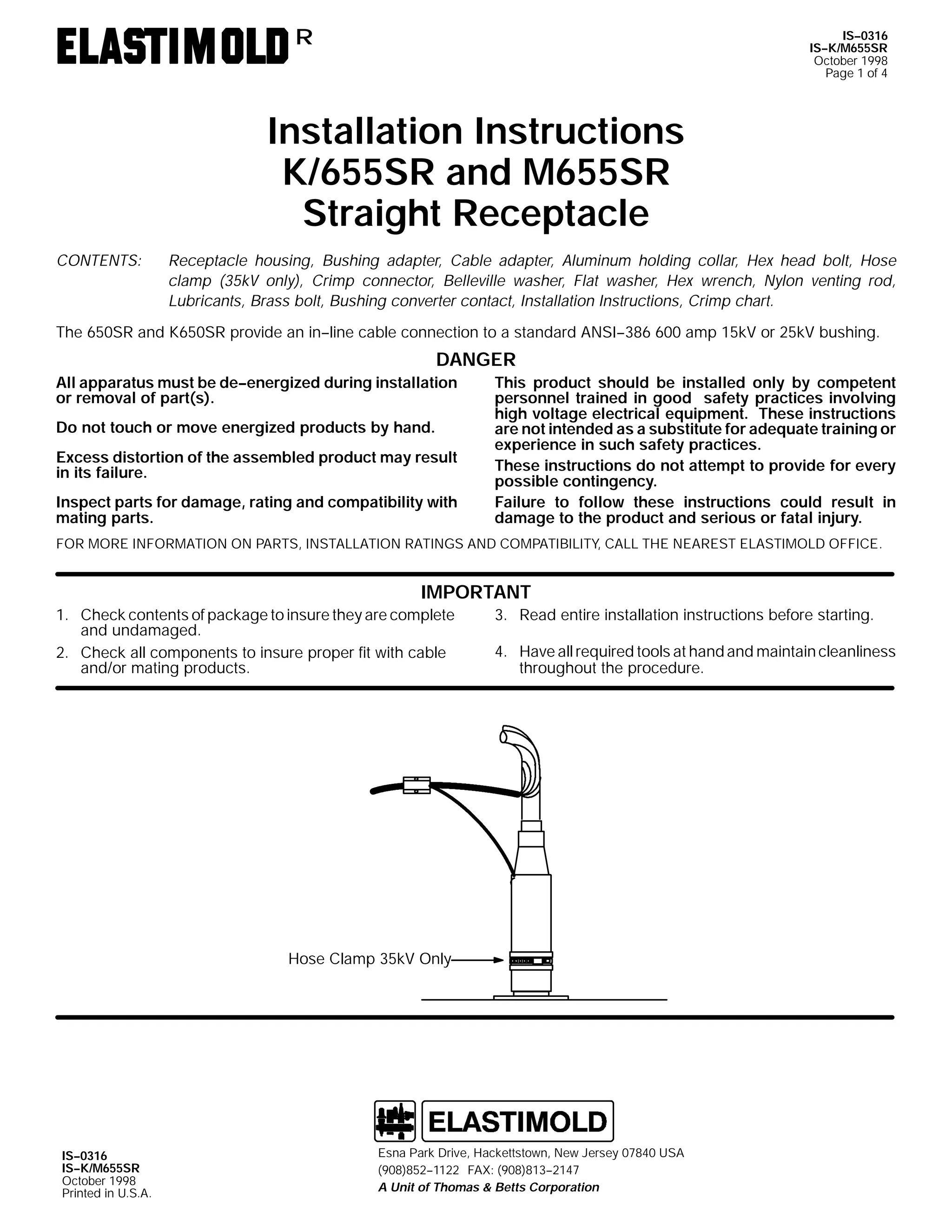
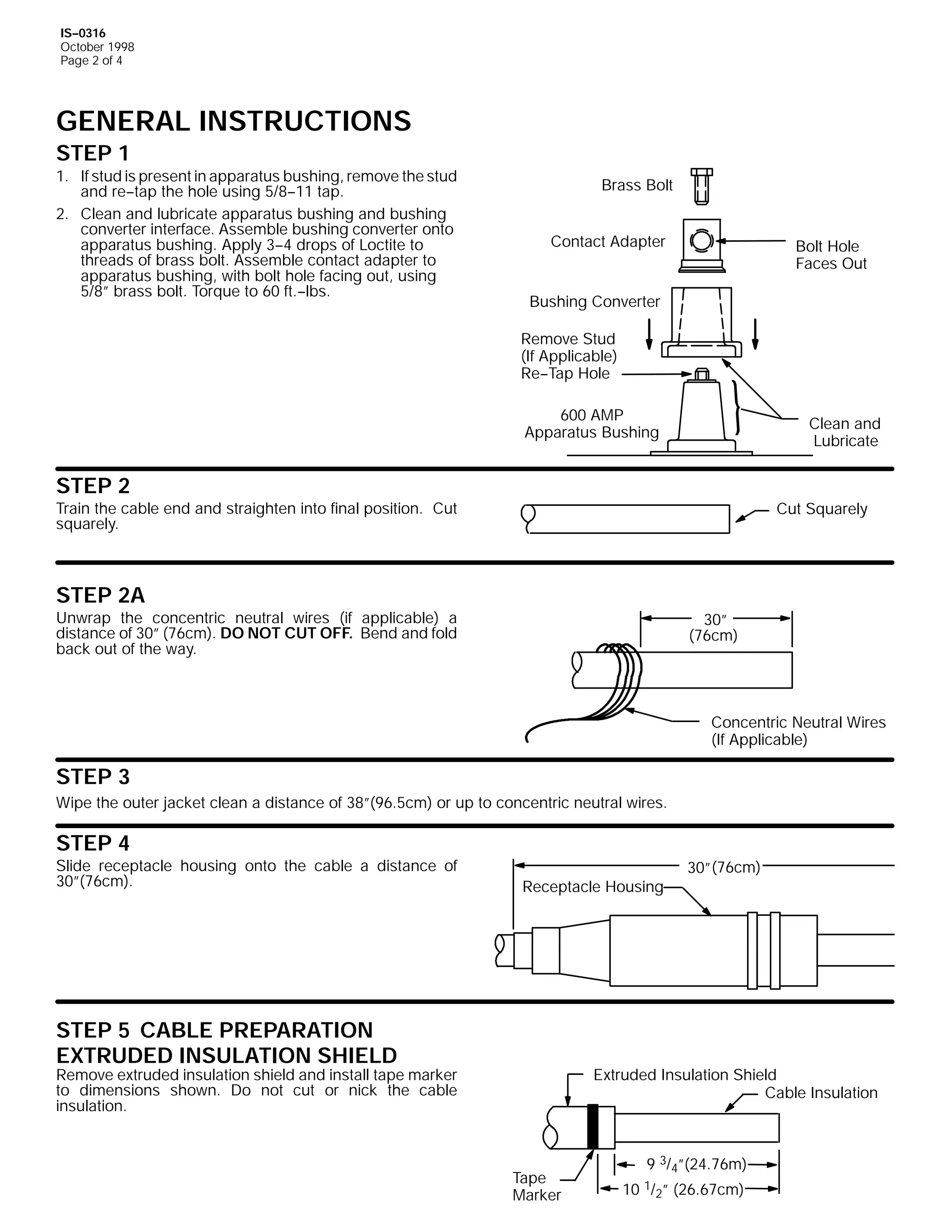
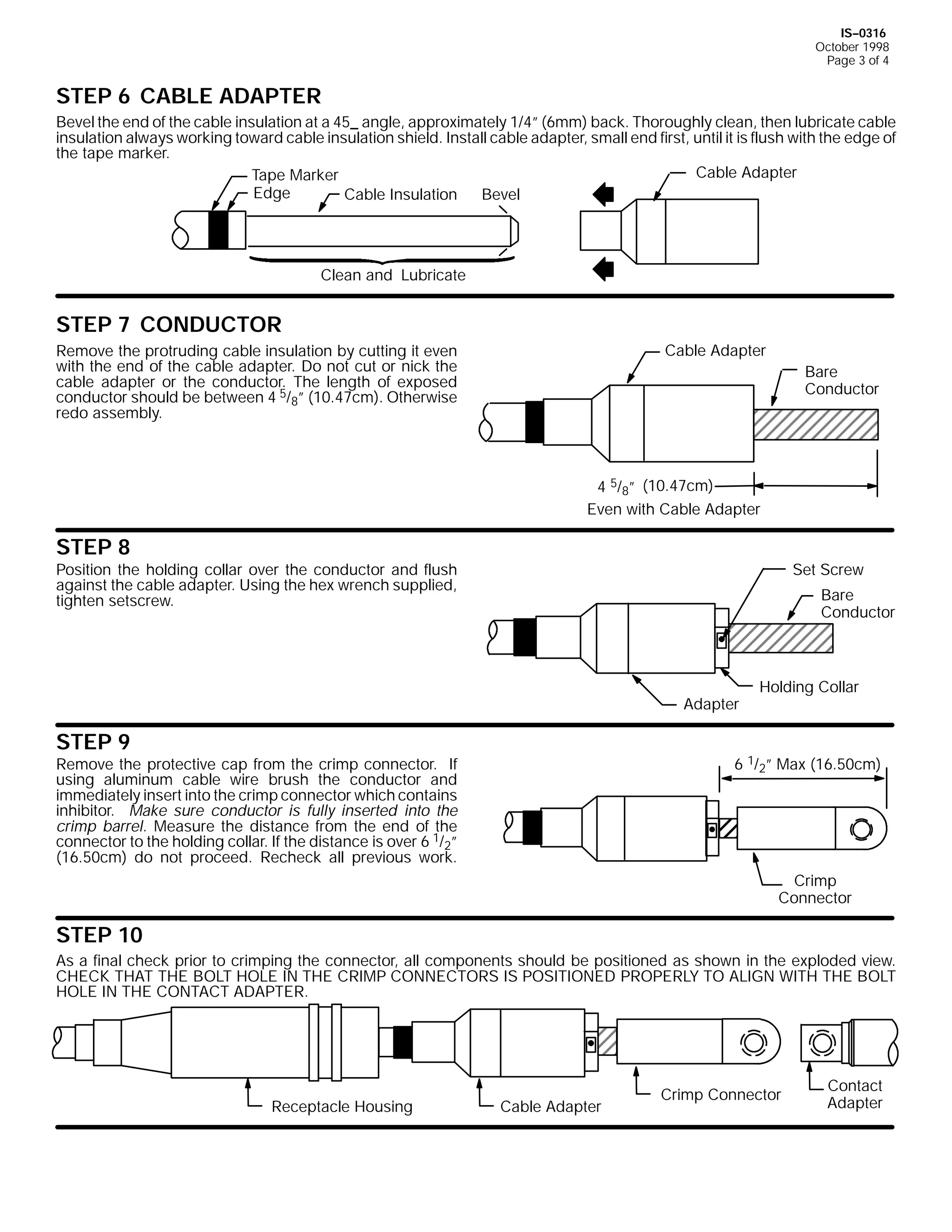
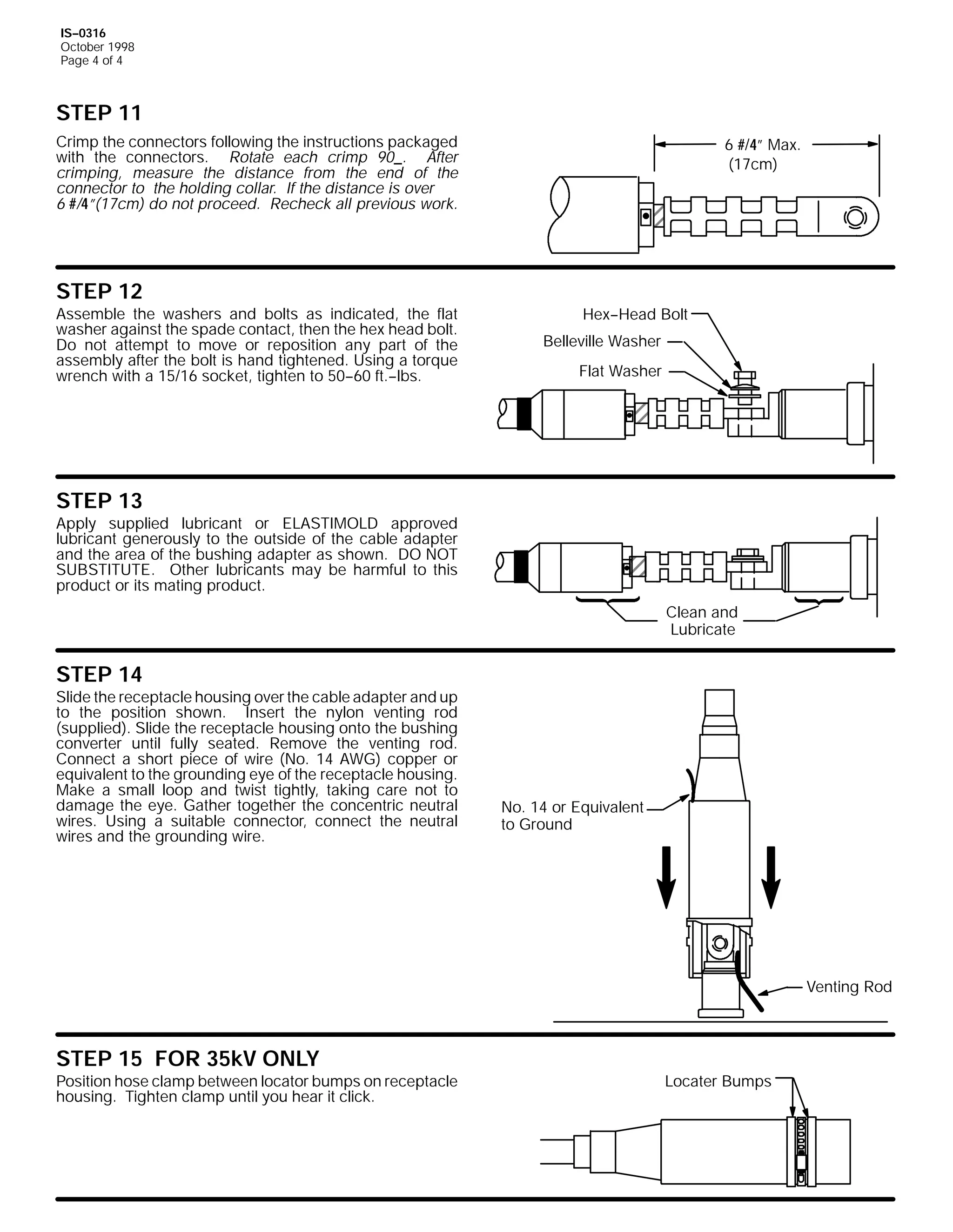
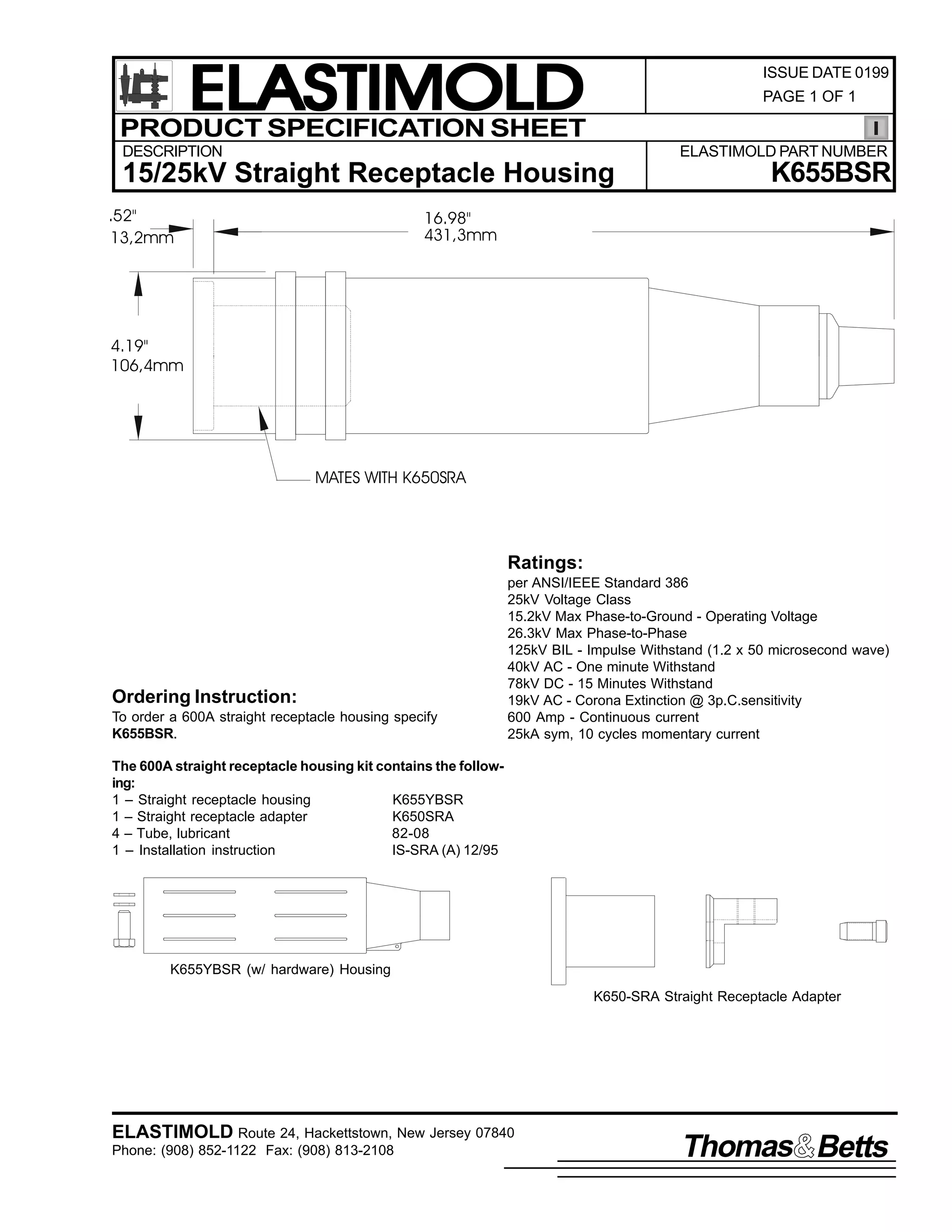
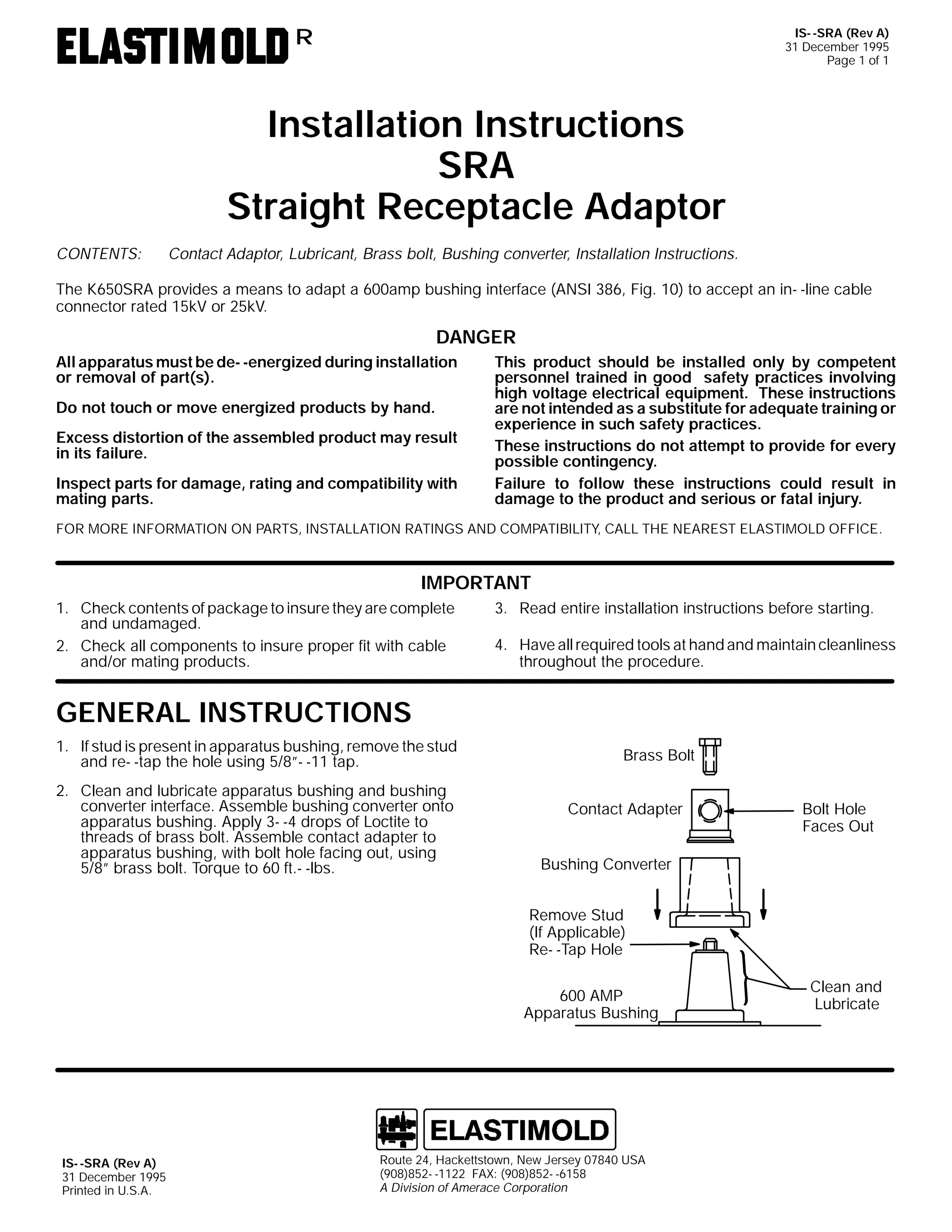
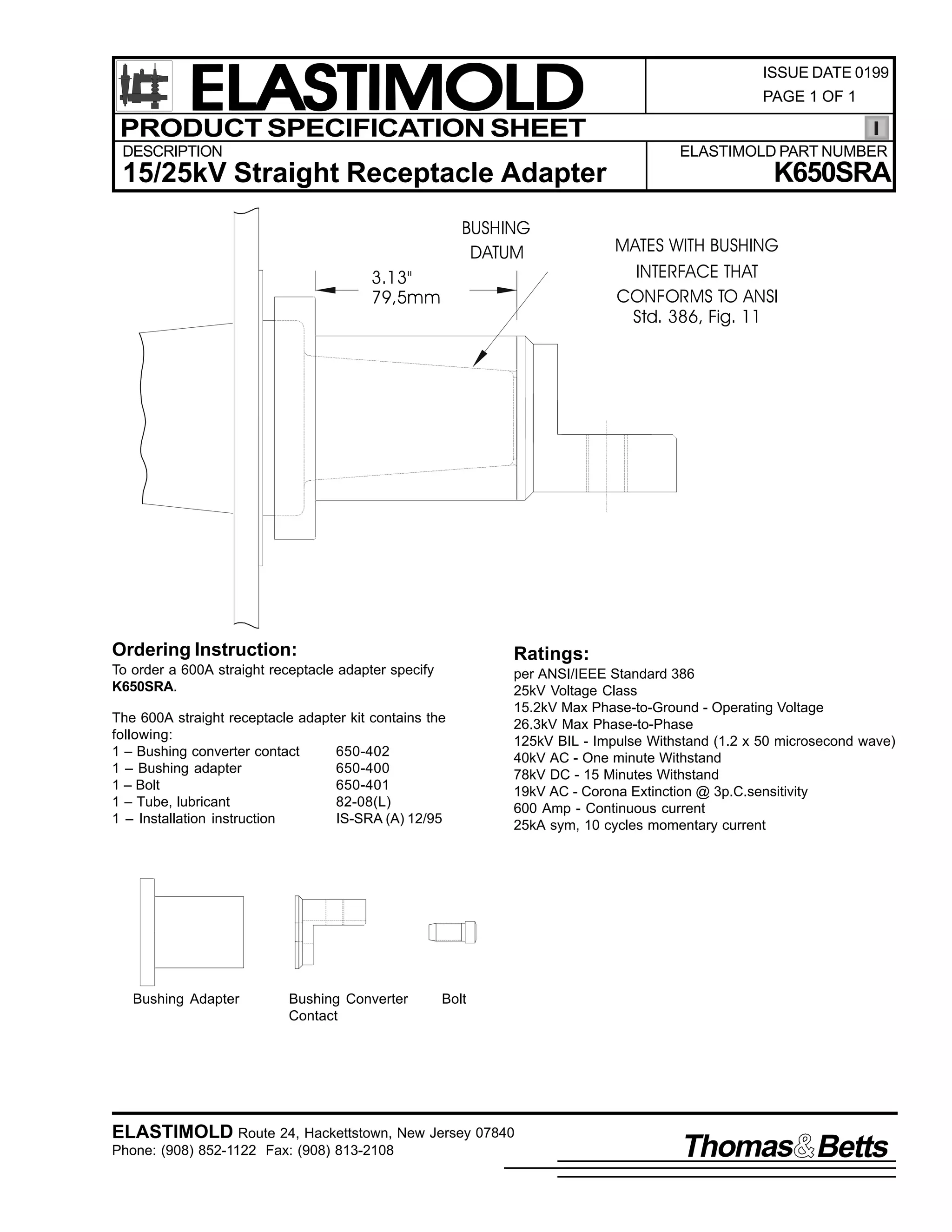
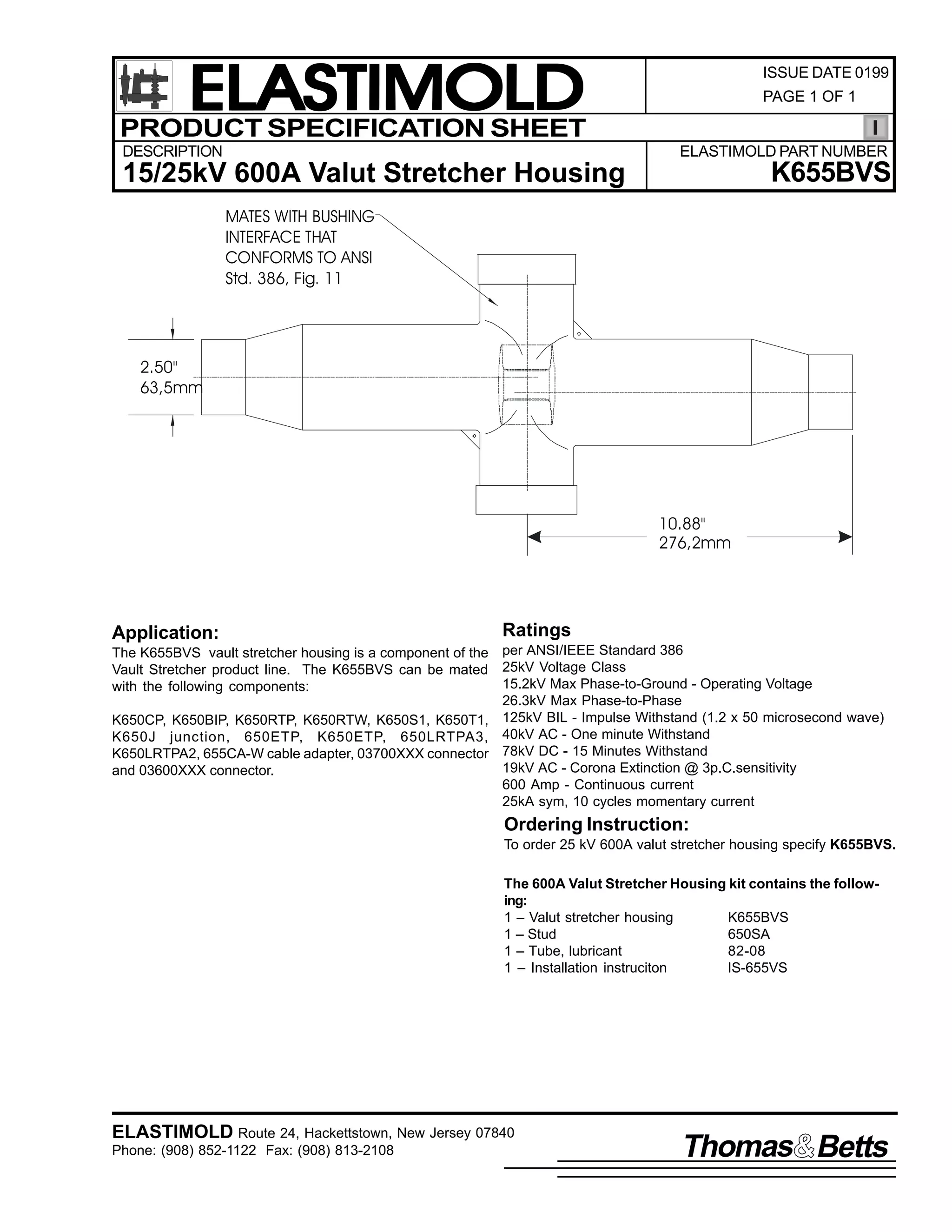
![9
&217(176=
,60 098896
48 'HFHPEHU 4<<6
3DJH 4 RI 8
,QVWDOODWLRQ ,QVWUXFWLRQV
98896 2 .98896
9DXOW 6WUHWFKHU
9DXOW 6WUHWFKHU/ 50 0&DEOH $GDSWHUV/ 50 0&RPSUHVVLRQ /XJV/ 50 0,QVXODWLQJ 3OXJV/ /XEULFDQW/ 6WXG 3UHSDFN/
,QVWDOODWLRQ ,QVWUXFWLRQV/ &ULPS FKDUW1
7KH 98896 DQG .98896 FRQQHFWRUV DUH GHVLJQHG WR= 4, SURYLGH IXOO VKLHOGHG/ IXOO VXEPHUVLEOH GHDGIURQW FDEOH FRQQHF0
WLRQV WR KLJK YROWDJH DSSDUDWXV DQG 5, SURYLGH D PHDQV WR VSOLFH DQG WDS 9330 0DPSHUH VVWHPV1 7KH FRQQHFWRUV DUH UDWHG
IRU XVH RQ 48N9 DQG 58N9 FODVV VVWHPV UHVSHFWLYHO1
'$1*(5
$OO DSSDUDWXV PXVW EH GH0 0HQHUJL]HG GXULQJ LQVWDOODWLRQ
RU UHPRYDO RI SDUW+V,1
'R QRW WRXFK RU PRYH HQHUJL]HG SURGXFWV E KDQG1
([FHVV GLVWRUWLRQ RI WKH DVVHPEOHG SURGXFW PD UHVXOW
LQ LWV IDLOXUH1
,QVSHFW SDUWV IRU GDPDJH/ UDWLQJ DQG FRPSDWLELOLW ZLWK
PDWLQJ SDUWV1
7KLV SURGXFW VKRXOG EH LQVWDOOHG RQO E FRPSHWHQW
SHUVRQQHO WUDLQHG LQ JRRG VDIHW SUDFWLFHV LQYROYLQJ
KLJK YROWDJH HOHFWULFDO HTXLSPHQW1 7KHVH LQVWUXFWLRQV
DUH QRW LQWHQGHG DV D VXEVWLWXWH IRU DGHTXDWH WUDLQLQJ RU
H[SHULHQFH LQ VXFK VDIHW SUDFWLFHV1
7KHVH LQVWUXFWLRQV GR QRW DWWHPSW WR SURYLGH IRU HYHU
SRVVLEOH FRQWLQJHQF1
)DLOXUH WR IROORZ WKHVH LQVWUXFWLRQV FRXOG UHVXOW LQ
GDPDJH WR WKH SURGXFW DQG VHULRXV RU IDWDO LQMXU1
7KLV SURGXFW LV VXSSOLHG ZLWK D SURWHFWLYH VKLSSLQJ FDS1
5HPRYH WKLV VKLSSLQJ FDS DQG UHSODFH ZLWK WKH
DSSURSULDWH +9 LQVXODWHG2VKLHOGHG FRQQHFWRU EHIRUH
VXEPHUJLQJ RU HQHUJL]LQJ WKH FLUFXLW1
)25 025( ,1)250$7,21 21 3$576/ ,167$//$7,21 5$7,1*6 $1' &203$7,%,/,7</ &$// 7+( 1($5(67 (/$67,02/' 2)),&(1
,03257$17
41 &KHFN FRQWHQWV RI SDFNDJH WR LQVXUH WKH DUH FRPSOHWH
DQG XQGDPDJHG1
51 &KHFN DOO FRPSRQHQWV WR LQVXUH SURSHU ILW ZLWK FDEOH
DQG2RU PDWLQJ SURGXFWV1
61 5HDG HQWLUH LQVWDOODWLRQ LQVWUXFWLRQV EHIRUH VWDUWLQJ1
71 +DYH DOO UHTXLUHG WRROV DW KDQG DQG PDLQWDLQ FOHDQOLQHVV
WKURXJKRXW WKH SURFHGXUH1
67(3 4
)RU FRQFHQWULF QHXWUDO FDEOH/ RYHUODS ERWK FDEOHV DQG FXW WR 47l +688PP, IURP FHQWHU OLQH RI MRLQW DQG EHQG EDFN WKH
FRQFHQWULF QHXWUDO ZLUHV1
47l
+688PP,
-RLQW &HQWHUOLQH
&RQFHQWULF 1HXWUDO :LUHV
+:KHUH $SSOLFDEOH,
47l
+688PP,
,60 098896
48 'HFHPEHU 4<<6
3ULQWHG LQ 8161$1
5RXWH 57/ +DFNHWWVWRZQ/ 1HZ -HUVH 3:;73 86$
+<3;,;850 04455 )$;= +<3;,;460 053<7](https://image.slidesharecdn.com/elastimold-140130102426-phpapp02/75/Elastimold-Connectors-Loadbreak-Deadbreak-Elbow-Bolted-Tee-Connectors-HV-MV-700-Series-317-2048.jpg)
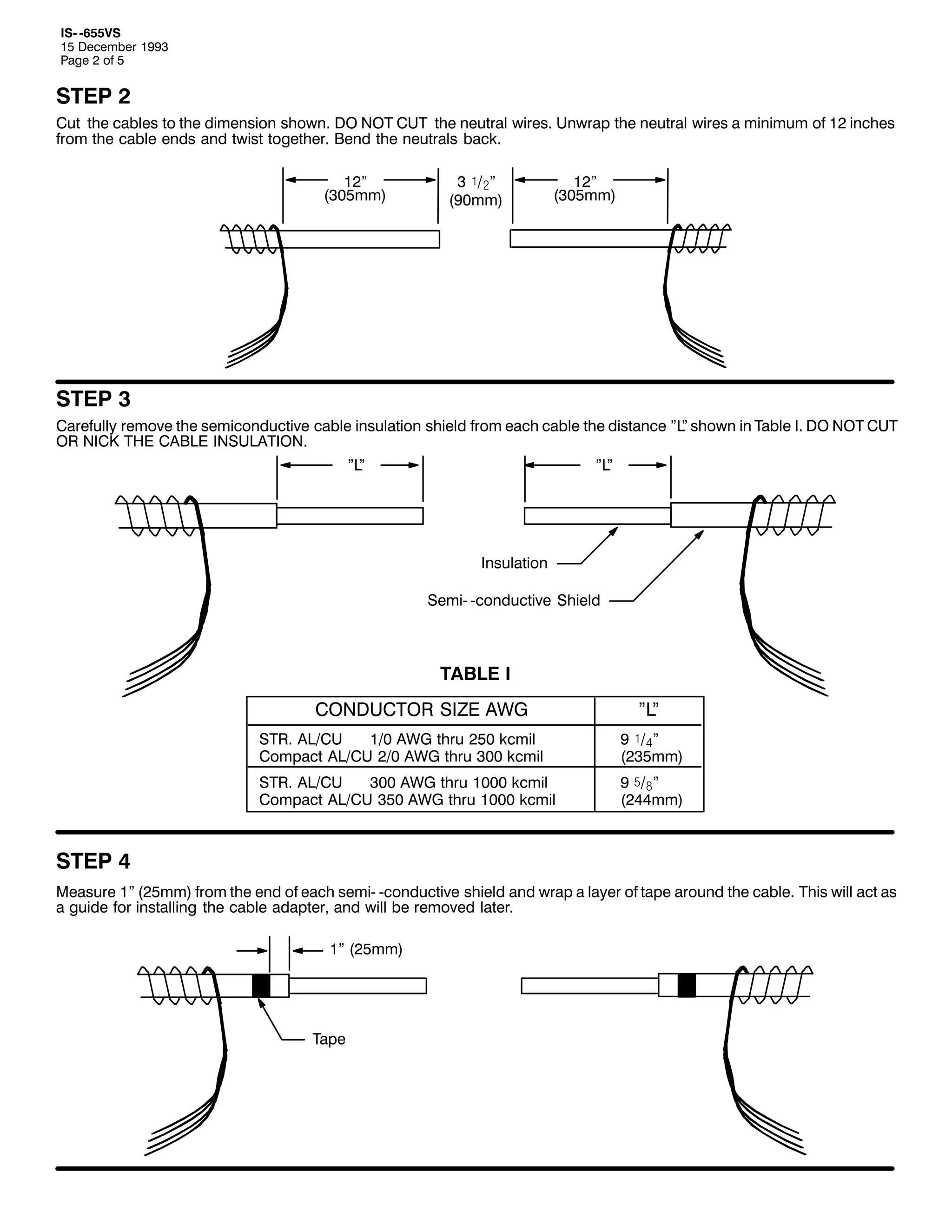
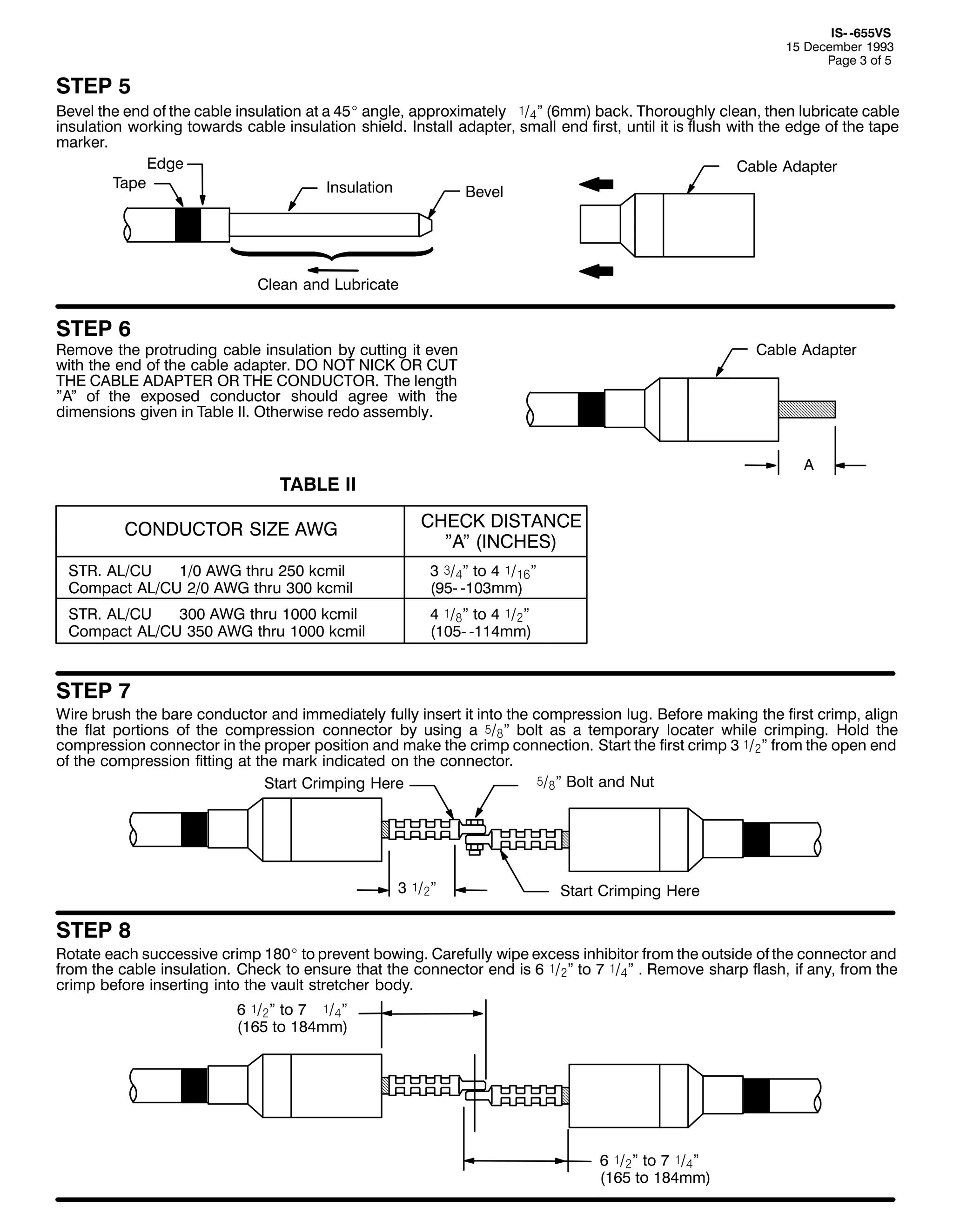
![,60 098896
48 'HFHPEHU 4<<6
3DJH 7 RI 8
67(3 <
41 /XEULFDWH WKH LQVLGH RI WKH YDXOW VWUHWFKHU ERG DQG WKH RXWVLGH RI WKH FDEOH DGDSWHU1 8VLQJ D URWDWLQJ PRWLRQ/ VOLS WKH
ERG RQWR WKH FDEOH DGDSWHU1 0DNH VXUH WKH FRPSUHVVLRQ OXJ LV DOLJQHG WR VHDW ZLWK WKH LQVLGH PDWLQJ SRUWLRQ RI WKH
YDXOW VWUHWFKHU1 7KH FRPSUHVVLRQ OXJ VKRXOG EH SXVKHG LQWR WKH YDXOW VWUHWFKHU XQWLO LW FDQQRW DGYDQFH IXUWKHU1 7KH
EDVH RI WKH DGDSWHU VKRXOG VWLOO EH DOLJQHG ZLWK WKH PDUNLQJ WDSH1
51 7R LQVWDOO WKH FRPSUHVVLRQ OXJ DQG DGDSWHU LQ WKH RWKHU VLGH/ WKH YDXOW VWUHWFKHU DQG FRPSUHVVLRQ OXJ PXVW EH SXVKHG
VLGHZDV XQWLO WKH FRPSUHVVLRQ OXJ HQWHUV WKH RSHQ HQG RI WKH YDXOW VWUHWFKHU ERG1
61 6ORZO SXVK ERWK XQLWV WRZDUG WKHLU QRUPDO DOLJQPHQW/ PDNLQJ VXUH WKH OXEULFDWHG DGDSWHU LV VOLGLQJ LQWR SURSHU
SRVLWLRQ LQ WKH YDXOW VWUHWFKHU1 7KH ORFDWLRQ RI WKH FRPSUHVVLRQ OXJ FDQ EH FKHFNHG E ORRNLQJ LQ WKH WDS KROH RI WKH
YDXOW VWUHWFKHU1 :KHQ FRPSUHVVLRQ OXJ LV IXOO VHDWHG/ PDNH VXUH WKDW ERWK FDEOH DGDSWHUV DUH VWLOO IOXVK ZLWK WDSH
PDUNHUV1 ,I QRW/ UHSRVLWLRQ FDEOH DGDSWHUV1 5HPRYH WDSH PDUNHUV1
/XEULFDWH
)OXVK
)OXVK
0DUNLQJ 7DSH
+5HPRYH,
0DUNLQJ 7DSH
+5HPRYH,
67(3 43
127(= $ VSHFLDO VWXG +98396$, ó2ãl ORQJHU WKDQ WKH VWDQGDUG VWXG PXVW EH XVHG ZLWK WKH YDXOW VWUHWFKHU1
41 '2 127 FRQQHFW RU GLVFRQQHFW PDWLQJ SURGXFWV ZKLOH HQHUJL]HG1 '2 127 HQHUJL]H ZKLOH GLVFRQQHFWHG1 5HPRYH
SURWHFWLYH FDSV IURP WKH YDXOW VWUHWFKHU DQG WKH PDWLQJ SDUW1 +DQG WLJKWHQ VWXG VXSSOLHG ZLWK YDXOW VWUHWFKHU LQWR RQH
PDWLQJ SDUW1 &OHDQ DQG OXEULFDWH ERWK WKH YDXOW VWUHWFKHU DQG WKH PDWLQJ SDUW ZLWK OXEULFDQW VXSSOLHG1+.HHS VXUIDFHV
RI YDXOW VWUHWFKHU DQG PDWLQJ SDUW FOHDQ,1
51 &OHDQ DQG OXEULFDWH WKH PDWLQJ SDUW IRU WKH RSSRVLWH HQG RI WKH YDXOW VWUHWFKHU1 ,QVHUW WKH PDWLQJ SDUW LQWR WKH HOERZ1
(QJDJH WKH WKUHDGV DQG KDQG WLJKWHQ1 7RUTXH PDWLQJ SDUW DFFRUGLQJ WR WKH LQVWUXFWLRQV VXSSOLHG ZLWK WKH PDWLQJ SDUW1
127(= $OO PDWLQJ SDUWV PXVW EH RSHUDWHG LQ DFFRUGDQFH ZLWK WKHLU RSHUDWLQJ LQVWUXFWLRQ1
5 ï2#l +9:PP,
6SHFLDO &RQYHUVLRQ 6WXG
/RDGEUHDN
5HGXFLQJ
7DS 3OXJ
'HDGEUHDN
5HGXFLQJ
7DS 3OXJ
&RQQHFWLQJ
3OXJ
,QVXODWLQJ 3OXJ
&OHDQ
)
/XEULFDWH
&OHDQ
)
/XEULFDWH
&OHDQ ) /XEULFDWH
,QVXODWLQJ 3OXJ RU
$SSDUDWXV %XVKLQJ
5HGXFLQJ
7DS :HOO
&OHDQ
)
/XEULFDWH](https://image.slidesharecdn.com/elastimold-140130102426-phpapp02/75/Elastimold-Connectors-Loadbreak-Deadbreak-Elbow-Bolted-Tee-Connectors-HV-MV-700-Series-320-2048.jpg)
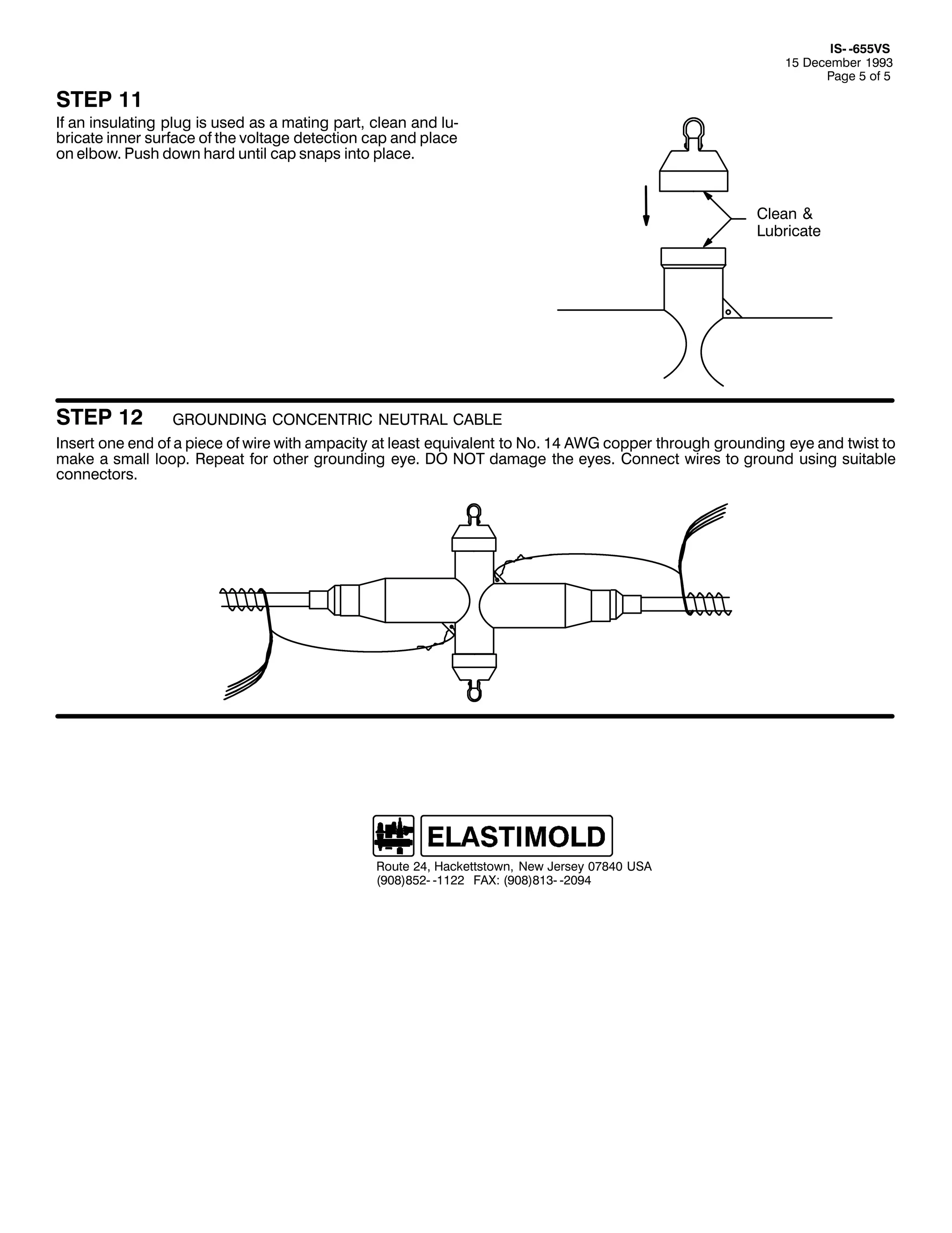
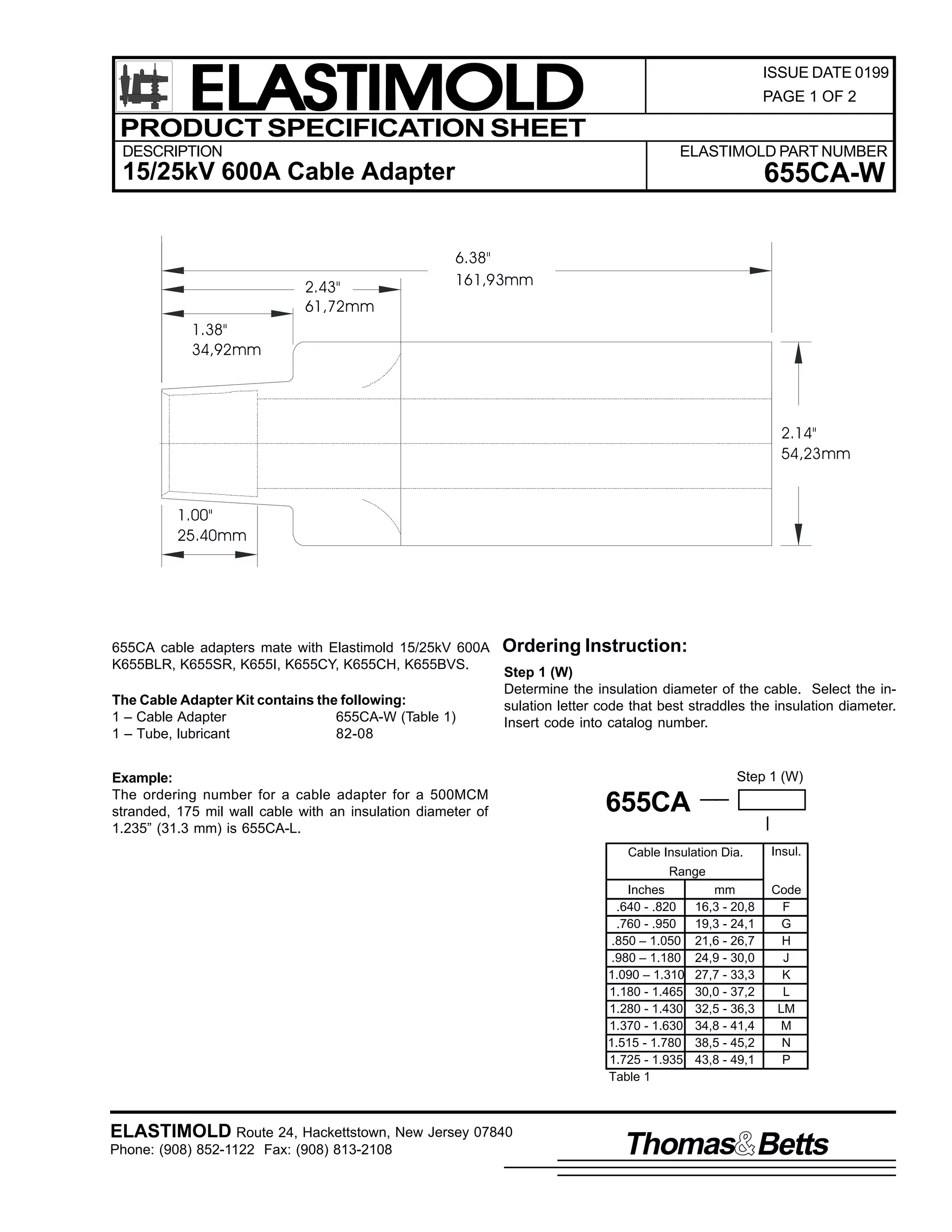
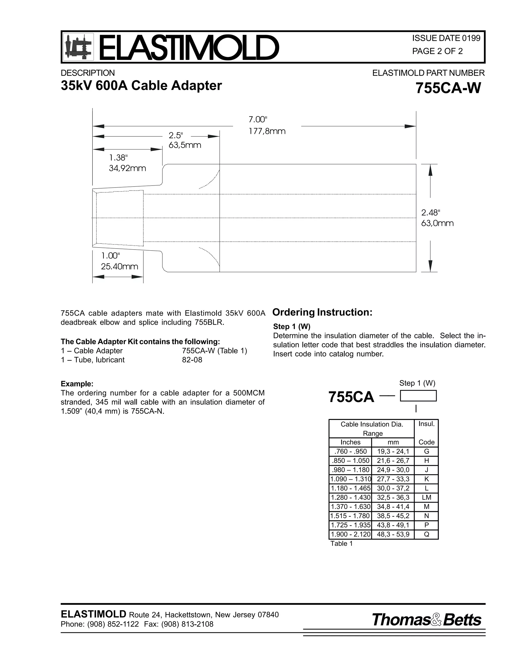
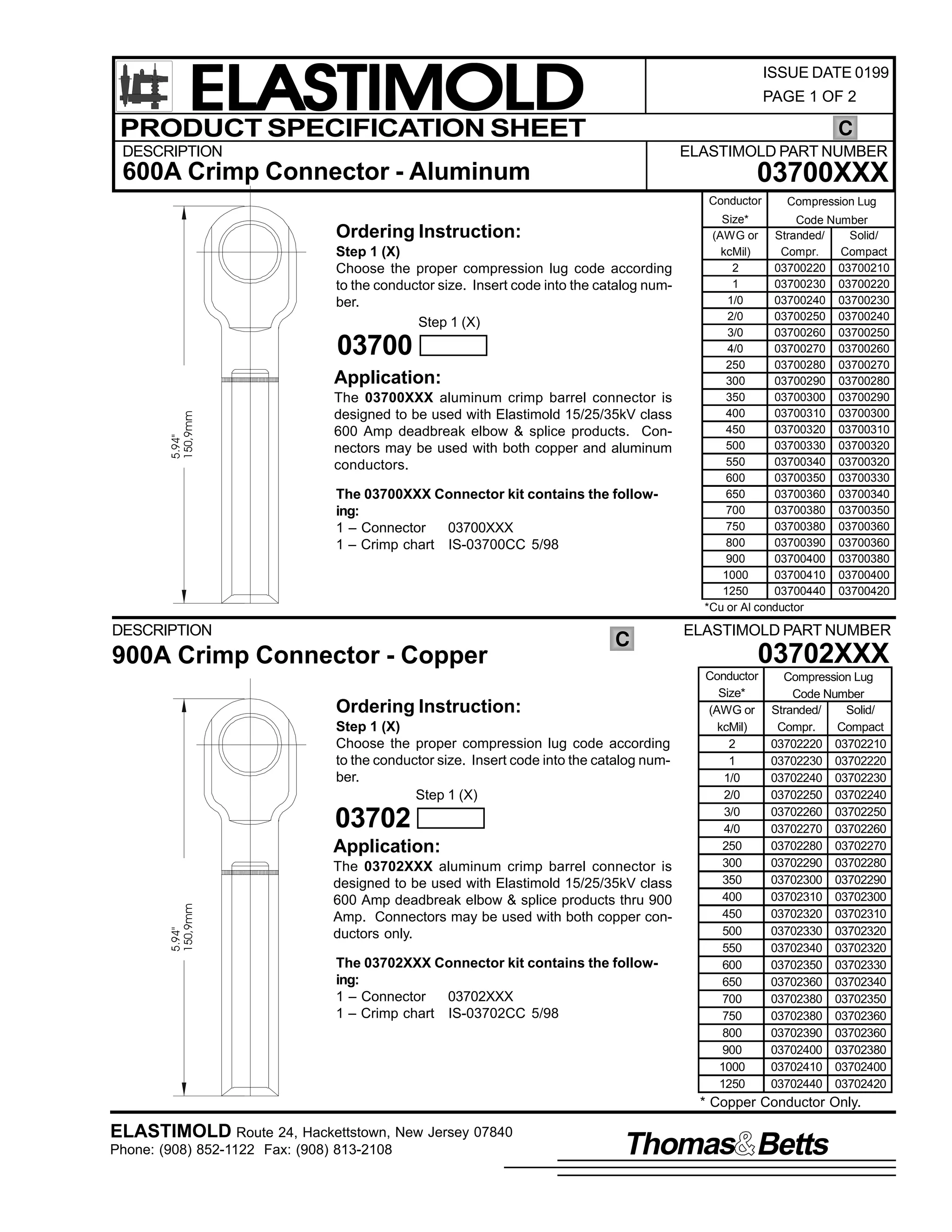

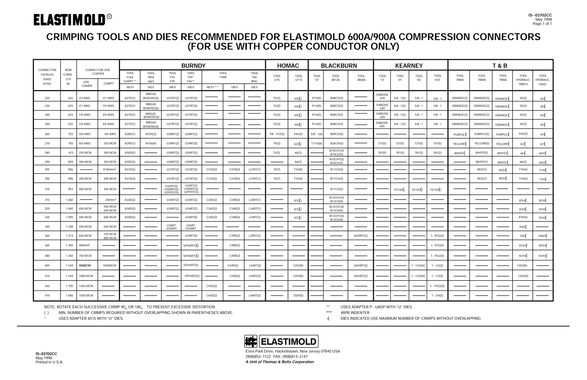
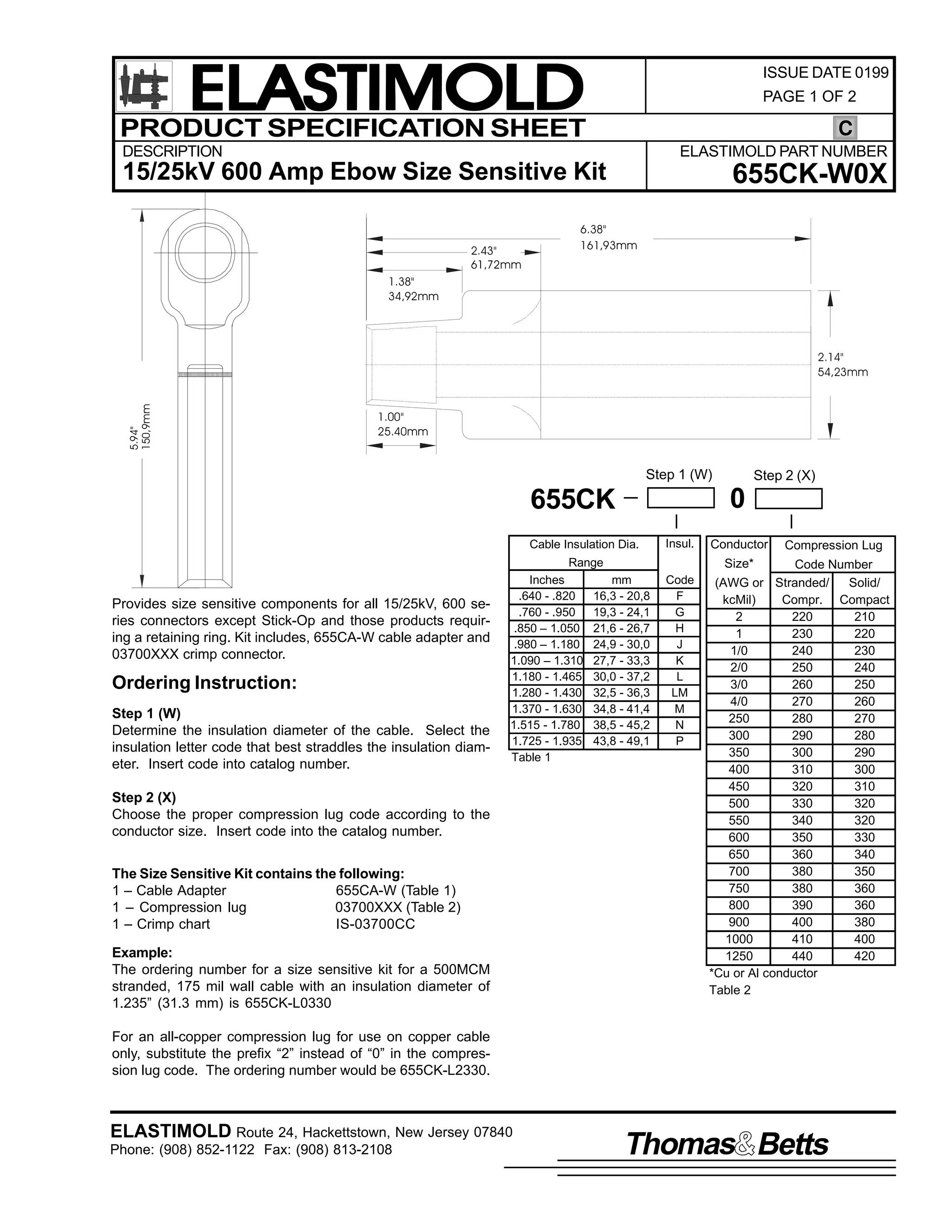
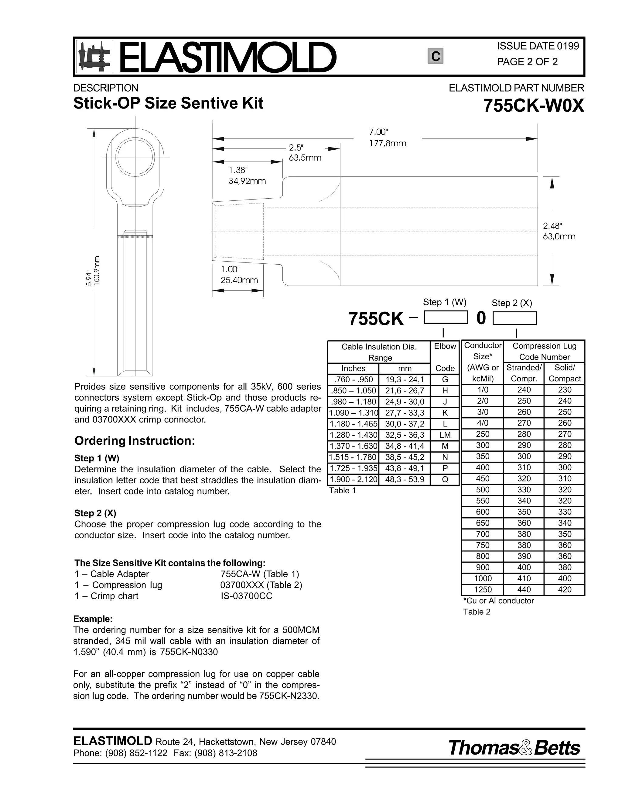
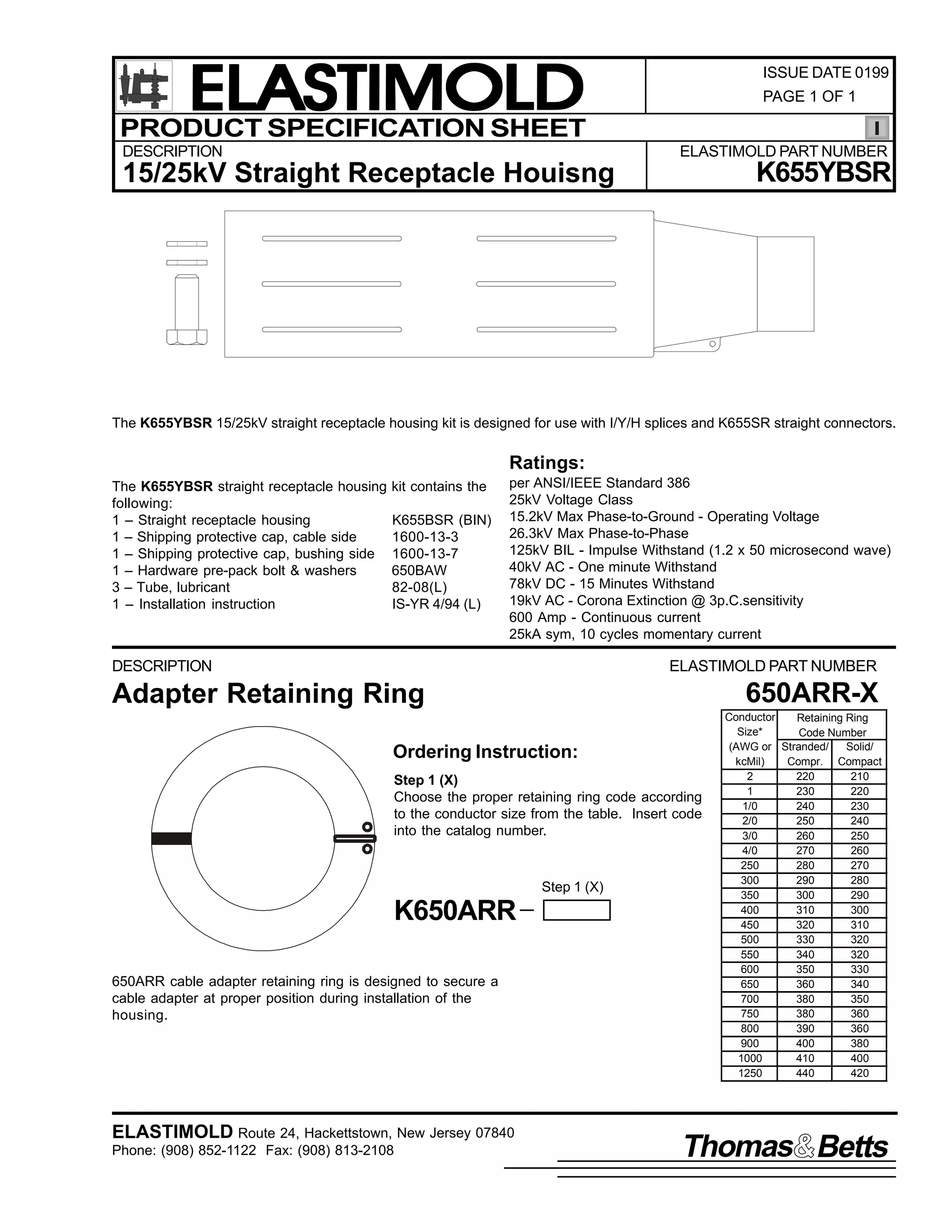
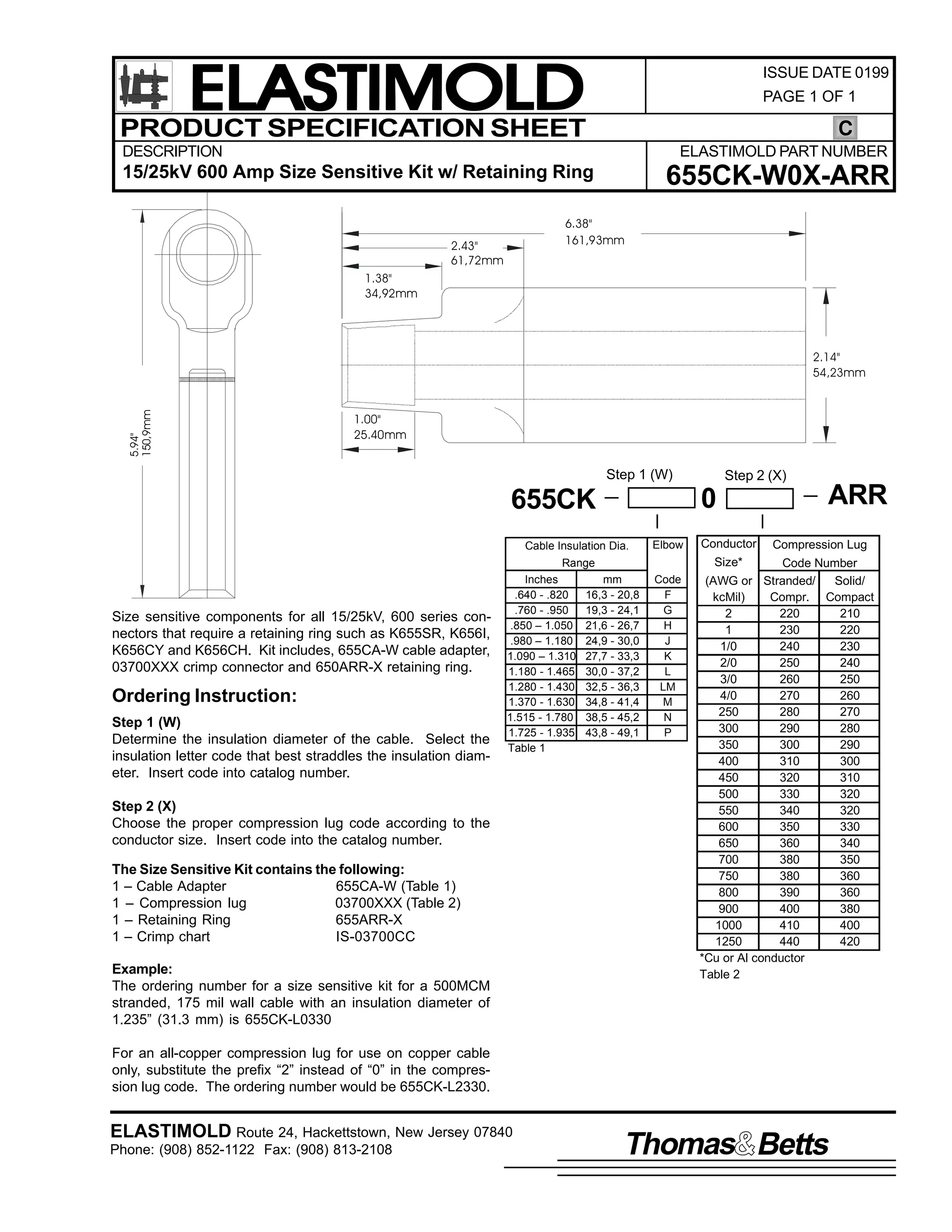
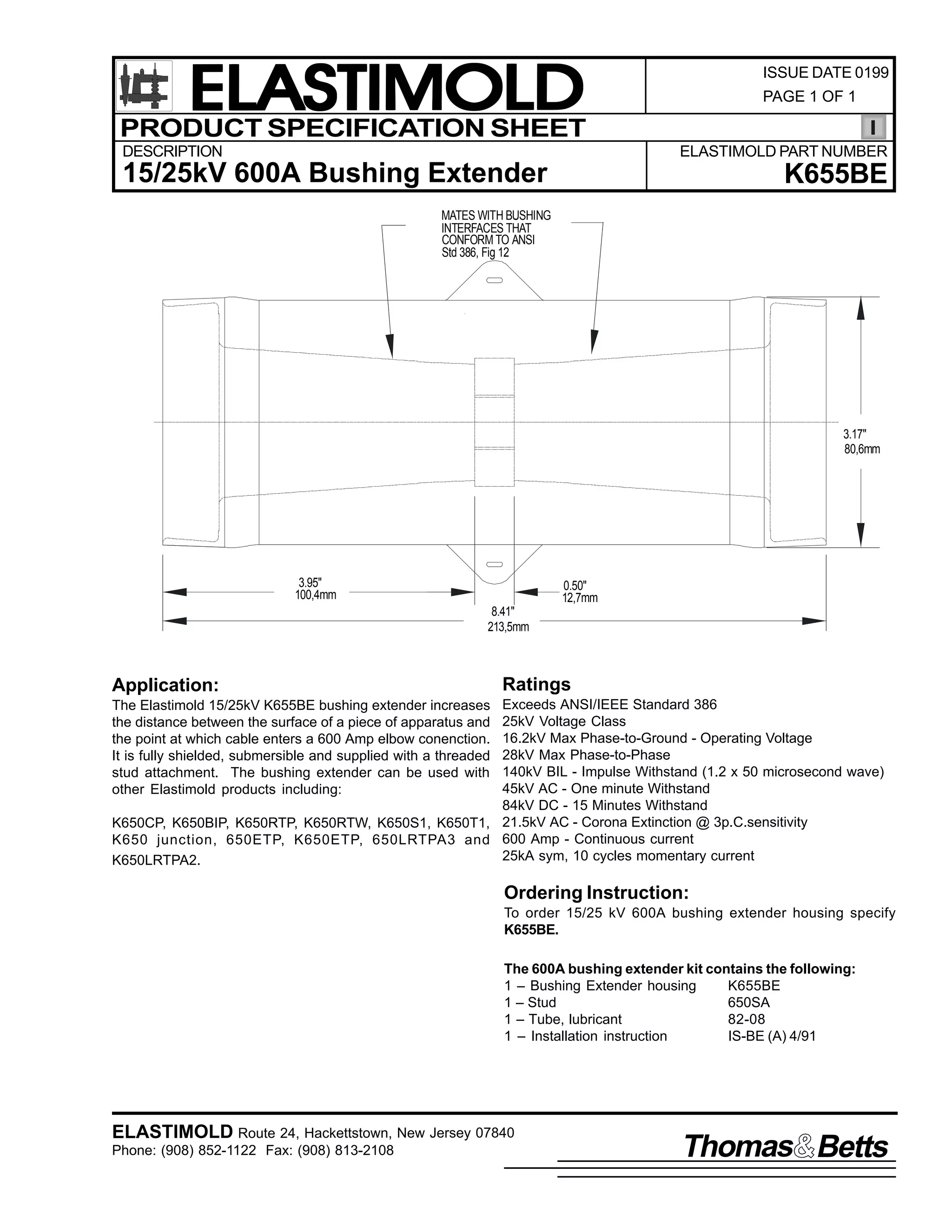
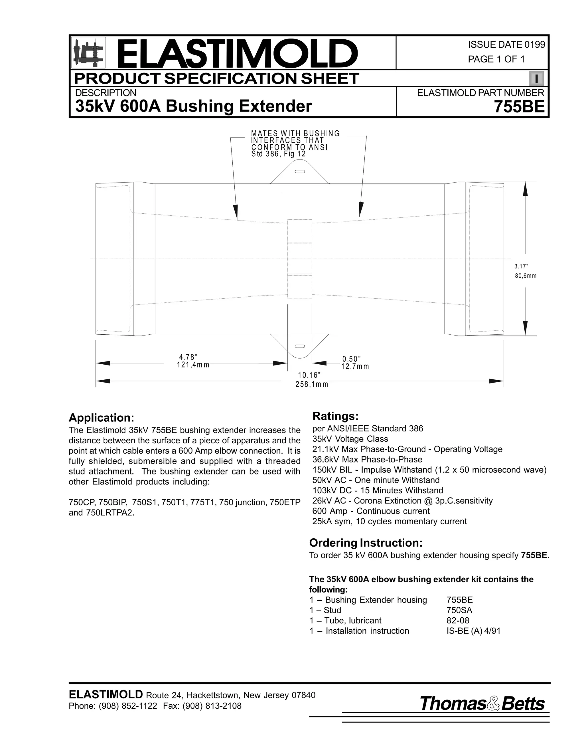
![9
,60 0%( +5HY $,
48 $SULO 4<<4
3DJH 4
,QVWDOODWLRQ ,QVWUXFWLRQV
48/58/68N9
9332<33 $03
%XVKLQJ ([WHQVLRQ
&217(176= %XVKLQJ ([WHQVLRQ/ /XEULFDQW +'2 127 68%67,787(,/ ,QVWDOODWLRQ ,QVWUXFWLRQ/ 6WXG 3UHSDFN
7KH EXVKLQJ H[WHQVLRQV ZLWK YROWDJH DQG FXUUHQW UDWLQJV DV LQGLFDWHG RQ WKH SURGXFW ZKHQ XVHG ZLWK WKH DSSURSULDWH PDWLQJ
FRPSRQHQWV/ FDQ SURYLGH= 4, D 9332<33 DPSHUH EXVKLQJ H[WHQVLRQ/ 5, D 533 DPSHUH WDS RU 6, DQ LQVXODWHG VKLHOGHG DQG
ZDWHU0 0WLJKW FDS IRU D 9332<33 DPSHUH EXVKLQJ1
'$1*(5
SHUVRQQHO WUDLQHG LQ JRRG VDIHW SUDFWLFHV LQYROYLQJ
KLJK YROWDJH HOHFWULFDO HTXLSPHQW1 7KHVH LQVWUXFWLRQV
DUH QRW LQWHQGHG DV D VXEVWLWXWH IRU DGHTXDWH WUDLQLQJ RU
'R QRW WRXFK RU PRYH HQHUJL]HG FDEOHV DQG2RU SURGXFWV
H[SHULHQFH LQ VXFK VDIHW SUDFWLFHV1
E KDQG1
7KHVH LQVWUXFWLRQV GR QRW DWWHPSW WR SURYLGH IRU HYHU
SRVVLEOH FRQWLQJHQF1
([FHVV GLVWRUWLRQ RI WKH DVVHPEOHG SURGXFW PD UHVXOW
)DLOXUH WR IROORZ WKHVH LQVWUXFWLRQV FRXOG UHVXOW LQ GDP0
LQ LWV IDLOXUH1
DJH WR WKH SURGXFW DQG VHULRXV RU IDWDO LQMXU1
7KLV SURGXFW LV VXSSOLHG ZLWK D SURWHFWLYH VKLSSLQJ FRY0
,QVSHFW SDUWV IRU GDPDJH/ UDWLQJ DQG FRPSDWLELOLW ZLWK
HU1 5HPRYH WKLV VKLSSLQJ FRYHU DQG UHSODFH ZLWK WKH DS0
PDWLQJ SDUWV1
SURSULDWH +9 LQVXODWHG FDS RU FRQQHFWRU EHIRUH VXE0
PHUJLQJ RU HQHUJL]LQJ WKH FLUFXLW1
7KLV SURGXFW VKRXOG EH LQVWDOOHG RQO E FRPSHWHQW
)25 025( ,1)250$7,21 21 3$576/ ,167$//$7,21 5$7,1*6 $1' &203$7,%,/,7</ &$// 7+( 1($5(67 (/$60
7,02/' 2)),&(1
$OO DSSDUDWXV PXVW EH GH0 0HQHUJL]HG GXULQJ LQVWDOODWLRQ
RU UHPRYDO RI SDUW+V,1
,03257$17
41 &KHFN FRQWHQWV RI SDFNDJH WR LQVXUH LW LV FRPSOHWH
DQG XQGDPDJHG1
51 &KHFN DOO FRPSRQHQWV WR LQVXUH SURSHU ILW ZLWK FDEOH
DQG2RU PDWLQJ SURGXFWV1
61 5HDG HQWLUH LQVWDOODWLRQ LQVWUXFWLRQV EHIRUH VWDUWLQJ1
71 +DYH DOO UHTXLUHG WRROV DW KDQG DQG REVHUYH FOHDQOL0 0
QHVV WKURXJKRXW WKH SURFHGXUH1
67(3 4
5HPRYH SURWHFWLYH FDSV IURP WKH EXVKLQJ H[WHQVLRQ1
&OHDQ DQG OXEULFDWH WKH HQWLUH EXVKLQJ H[WHQVLRQ LQWHUIDFH
DV QRWHG/ ZLWK OXEULFDQW VXSSOLHG RU (/$67,02/' DS0
SURYHG OXEULFDQW1 .HHS PDWLQJ VXUIDFHV RI EXVKLQJ DQG H[0
WHQVLRQ FOHDQ1
&OHDQ DQG
/XEULFDWH
,60 0%( +5HY $,
48 $SULO 4<<4
3ULQWHG LQ 8161$1
5RXWH 57/ +DFNHWWVWRZQ/ 1HZ -HUVH 3:;73 86$
+<3;,;850 04455 )$;= +<3;,;850 0948;](https://image.slidesharecdn.com/elastimold-140130102426-phpapp02/75/Elastimold-Connectors-Loadbreak-Deadbreak-Elbow-Bolted-Tee-Connectors-HV-MV-700-Series-333-2048.jpg)
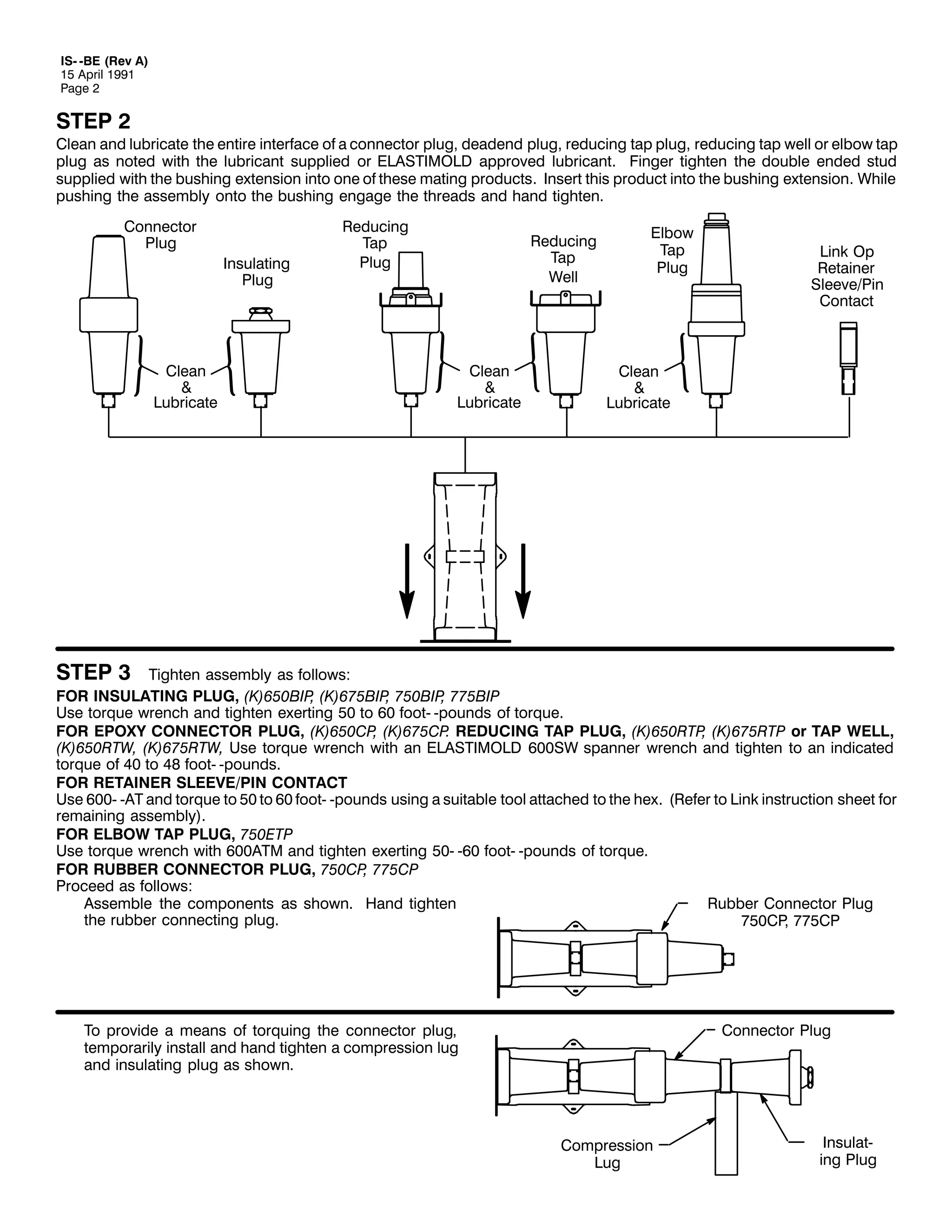
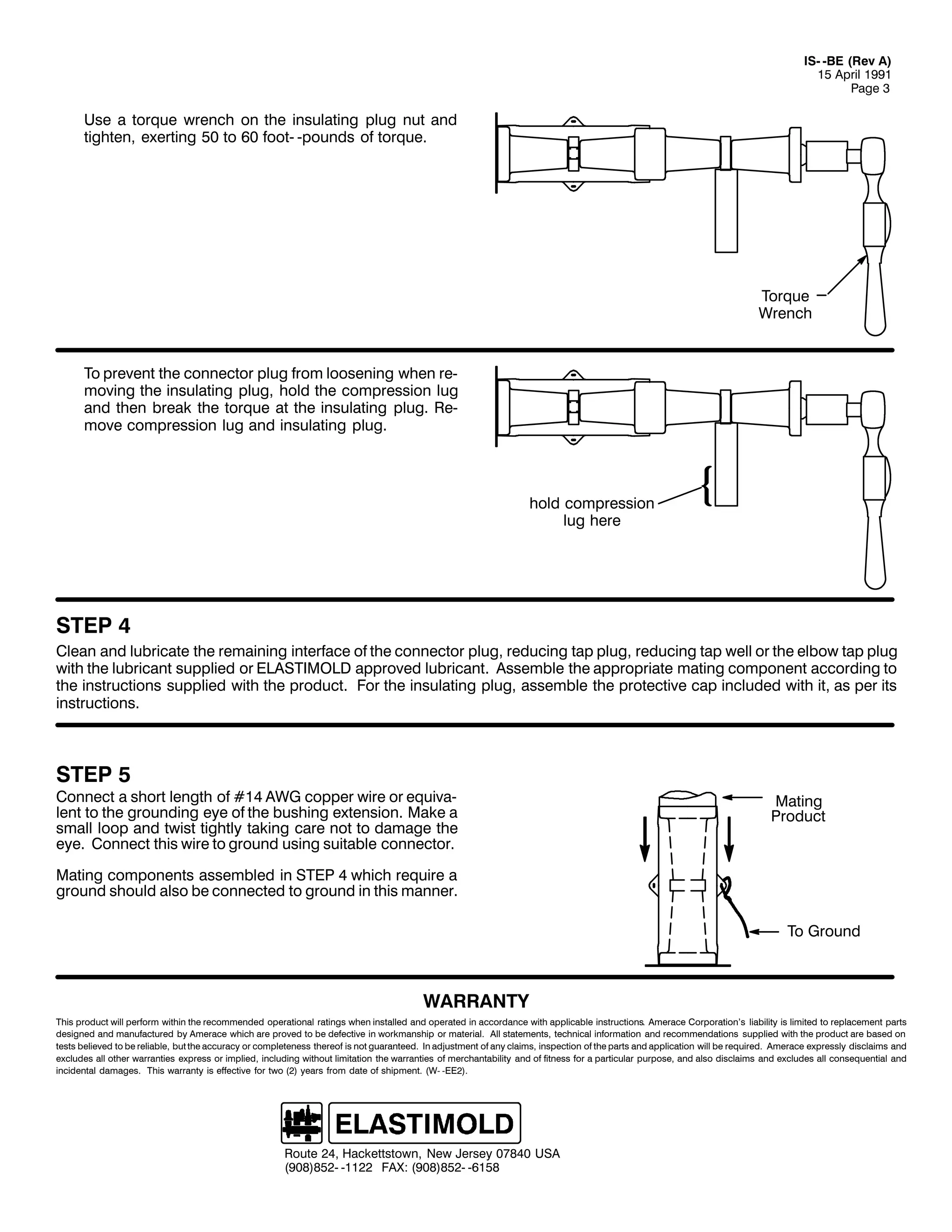
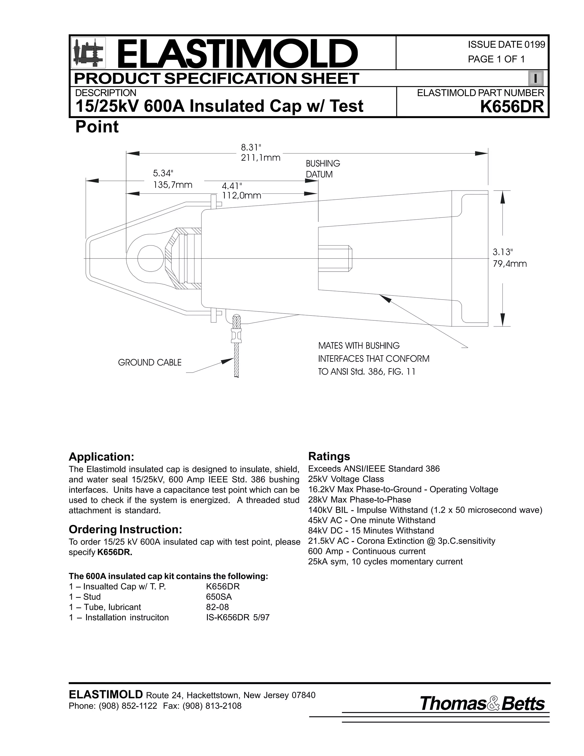

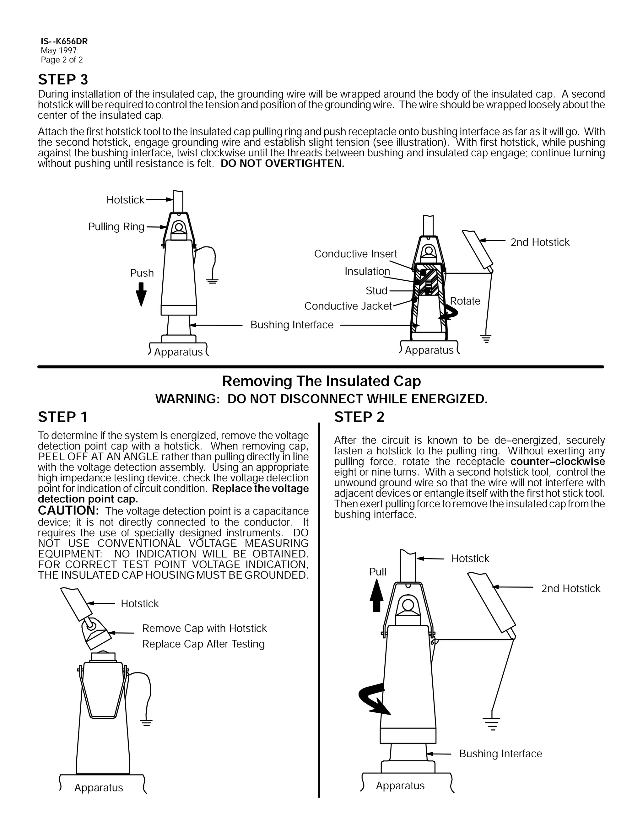
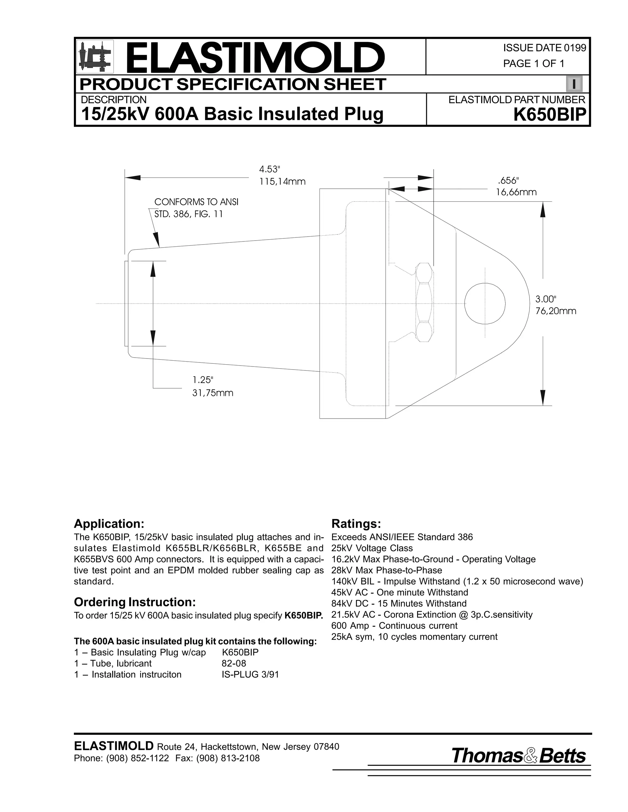
![9
,60 03OXJV
63 0DUFK 4<<4
3DJH 4 RI 5
,QVWDOODWLRQ ,QVWUXFWLRQV
48258268N9 9332<33 $03
3OXJ DQG :HOO 3URGXFWV
&217(176= 4003OXJ RU :HOO/ /XEULFDQW +'2 127 68%67,787(,/ 400,QVWDOODWLRQ ,QVWUXFWLRQV1
7KH SOXJ DQG ZHOO DUH SRZHU GLVWULEXWLRQ SURGXFW DFFHVVRULHV GHVLJQHG IRU XVH RQ 9332<33 DPSHUH VVWHPV1 7KH FDQ EH PDWHG
ZLWK D 933 DPSHUH HOERZ RU EXVKLQJ H[WHQVLRQ1 7KH FDQ DOVR EH XVHG RQ VLQJOH SKDVH ODWHUDOV RI 6 SKDVH FLUFXLWV1 5HIHU WR PDWLQJ
SURGXFW LQVWDOODWLRQ LQVWUXFWLRQV=
48258268N9 9332<33 DPS (OERZV
48258268N9 9332<33 DPS %XVKLQJ ([WHQVLRQV
'$1*(5
$OO DSSDUDWXV PXVW EH GH00HQHUJL]HG GXULQJ LQVWDOODWLRQ
RU UHPRYDO RI SDUW+V,1
'R QRW WRXFK RU PRYH HQHUJL]HG SURGXFWV E KDQG1
([FHVV GLVWRUWLRQ RI WKH DVVHPEOHG SURGXFW PD UHVXOW LQ
LWV IDLOXUH1
,QVSHFW SDUWV IRU GDPDJH/ UDWLQJ DQG FRPSDWLELOLW ZLWK
PDWLQJ SDUWV1
7KLV SURGXFW VKRXOG EH LQVWDOOHG RQO E FRPSHWHQW
SHUVRQQHO WUDLQHG LQ JRRG VDIHW SUDFWLFHV LQYROYLQJ
KLJK YROWDJH HOHFWULFDO HTXLSPHQW1 7KHVH LQVWUXFWLRQV
DUH QRW LQWHQGHG DV D VXEVWLWXWH IRU DGHTXDWH WUDLQLQJ RU
H[SHULHQFH LQ VXFK VDIHW SUDFWLFHV1
7KHVH LQVWUXFWLRQV GR QRW DWWHPSW WR SURYLGH IRU HYHU
SRVVLEOH FRQWLQJHQF1
)DLOXUH WR IROORZ WKHVH LQVWUXFWLRQV ZLOO UHVXOW LQ GDPDJH
WR WKH SURGXFW DQG VHULRXV RU IDWDO LQMXU1
7KLV SURGXFW LV VXSSOLHG ZLWK D SURWHFWLYH VKLSSLQJ
FRYHU1 5HPRYH WKLV VKLSSLQJ FRYHU DQG UHSODFH ZLWK WKH
DSSURSULDWH +9 LQVXODWHG FDS RU FRQQHFWRU EHIRUH
VXEPHUJLQJ RU HQHUJL]LQJ WKH FLUFXLW1
)25 025( ,1)250$7,21 21 3$576/ ,167$//$7,21 5$7,1*6 $1' &203$7,%,/,7</ &$// 7+( 1($5(67 (/$67,02/' 2)),&(1
,03257$17
41 &KHFN FRQWHQWV RI SDFNDJH WR LQVXUH WKH DUH FRPSOHWH
DQG XQGDPDJHG1
51 &KHFN DOO FRPSRQHQWV WR LQVXUH SURSHU ILW ZLWK FDEOH
DQG2RU PDWLQJ SURGXFWV1
67(3 4
5HPRYH SURWHFWLYH FDSV IURP WKH SOXJ RU ZHOO SURGXFW1 7KH
HOERZ DQG EXVKLQJ H[WHQVLRQ FRPH SDFNDJHG ZLWK D VWXG1 +DQG
WLJKWHQ WKH VWXG LQWR D 933DPS LQWHUIDFH RQ WKH SOXJ RU ZHOO LI WKH
933DPS PDWLQJ LQWHUIDFH LV QRW HTXLSSHG ZLWK D VWXG1 /XEULFDWH
ERWK WKH HOERZ DQG LWV PDWLQJ SDUW DV LQGLFDWHG ZLWK WKH OXEULFDQW
VXSSOLHG1 '2 127 68%67,787(1 2WKHU OXEULFDQWV PD EH
KDUPIXO WR WKH SURGXFWV1 %H VXUH WR NHHS VXUIDFHV RI HOERZ DQG
PDWLQJ SDUWV FOHDQ1
61 5HDG HQWLUH LQVWDOODWLRQ LQVWUXFWLRQV EHIRUH VWDUWLQJ1
71 +DYH DOO UHTXLUHG WRROV DW KDQG DQG PDLQWDLQ FOHDQOLQHVV
WKURXJKRXW WKH SURFHGXUH1
&RQQHFWRU
3OXJ
%DVLF
,QVXODWLQJ
3OXJ
5HGXFLQJ
7DS 3OXJ
5HGXFLQJ
7DS :HOO
/XEULFDWH
/XEULFDWH
6WXG
6WXG
/XEULFDWH
933$PS
0DWLQJ ,QWHUIDFH
,60 03OXJV
63 0DUFK 4<<4
3ULQWHG LQ 8161$1
$ 8QLW RI 7KRPDV ) %HWWV
(VQD 3DUN 'ULYH/ +DFNHWWVWRZQ/ 1HZ -HUVH 3:;73 86$
+<3;,;850 04455 )$;= +<3;,;460 0547:
(OERZ RU
%XVKLQJ ([WHQVLRQ](https://image.slidesharecdn.com/elastimold-140130102426-phpapp02/75/Elastimold-Connectors-Loadbreak-Deadbreak-Elbow-Bolted-Tee-Connectors-HV-MV-700-Series-340-2048.jpg)
![,60 03OXJV
63 0DUFK 4<<4
3DJH 5 RI 5
67(3 5
3XVK WKH SOXJ RU ZHOO LQWR WKH HOERZ RU EXVKLQJ H[WHQVLRQ DQG
HQJDJH WKH WKUHDGV1
3OXJ RU
:HOO
&RQWDFW
(OERZ RU
%XVKLQJ ([WHQVLRQ
67(3 6
)25 ,168/$7,1* 3/8*=
8VH WRUTXH ZUHQFK DQG WLJKWHQ H[HUWLQJ 83 WR 93 IRRW00SRXQGV RI WRUTXH1
)25 &211(&725 3/8*/ 7$3 3/8* 25 7$3 :(//=
8VH WRUTXH ZUHQFK ZLWK DQ (/$67,02/' 9336: VSDQQHU ZUHQFK1 6LQFH WKH LQGLFDWHG WRUTXH UHDGLQJ LV QRW WKH DFWXDO WRUTXH
DSSOLHG LQ WKLV FDVH/ WKH LQGLFDWHG WRUTXH VKRXOG EH IURP 73 WR 7; IRRW00SRXQGV1
)25 :83 6(5,(6 &211(&7,1* 3/8*=
5HIHU WR VSHFLDO LQVWUXFWLRQV +,600:83&3, SDFNDJHG ZLWK WKH :83&3 FRQQHFWRU SOXJ1
67(3 7
)RU LQVXODWLQJ SOXJ OXEULFDWH LQQHU VXUIDFH RI YROWDJH GHWHFWLRQ
FDS DQG SODFH RQ SOXJ DQG HOERZ1 3XVK GRZQ XQWLO FDS µVQDSVµ
LQWR SODFH1
/XEULFDWH
67(3 8 92/7$*( 7(67 21 ,168/$7,1* 3/8*
7KH (/$67,02/' LQVXODWLQJ SOXJ LV HTXLSSHG ZLWK DQ LQWHJUDO
FDSDFLWDQFH WHVW SRLQW WKDW FDQ EH XVHG WR HVWDEOLVK ZKHWKHU RU
QRW WKH FLUFXLW LV HQHUJL]HG1 :KHQ XVLQJ WKH WHVW SRLQW/
FRPSOHWH WKH IROORZLQJ VWHSV=
41
51
61
5HPRYH WHVW SRLQW FDS ZLWK D KRWVWLFN1
8VLQJ D VXLWDEOH VHQVLQJ GHYLFH SURFHHG WR GHWHUPLQH
LI FDEOH LV HQHUJL]HG1
&$87,21= 7KH YROWDJH WHVW SRLQW LV D FDSDFLWDQFH
GHYLFH> LW LV QRW GLUHFWO FRQQHFWHG WR WKH FRQQHFWRU1 ,W
UHTXLUHV WKH XVH RI VSHFLDOO GHVLJQHG LQVWUXPHQWV1 '2
127 86( &219(17,21$/ 92/7$*( 0($685,1*
(48,30(17> 12 ,1',&$7,21 :,// %( 2%7$,1('1
$IWHU YROWDJH GHWHFWLRQ KDV EHHQ PDGH/ FOHDQ DQG
OXEULFDWH WKH LQVLGH VXUIDFH RI WKH FDS ZLWK VLOLFRQH
JUHDVH DQG UHSODFH LW RQ WKH WHVW SRLQW1
$ 8QLW RI 7KRPDV ) %HWWV
(VQD 3DUN 'ULYH/ +DFNHWWVWRZQ/ 1HZ -HUVH 3:;73 86$
+<3;,;850 04455 )$;= +<3;,;460 0547:
7HVW 3RLQW &DS
+5HPRYH ZLWK
+RWVWLFN
&DSDFLWLYH
7HVW 3RLQW](https://image.slidesharecdn.com/elastimold-140130102426-phpapp02/75/Elastimold-Connectors-Loadbreak-Deadbreak-Elbow-Bolted-Tee-Connectors-HV-MV-700-Series-341-2048.jpg)
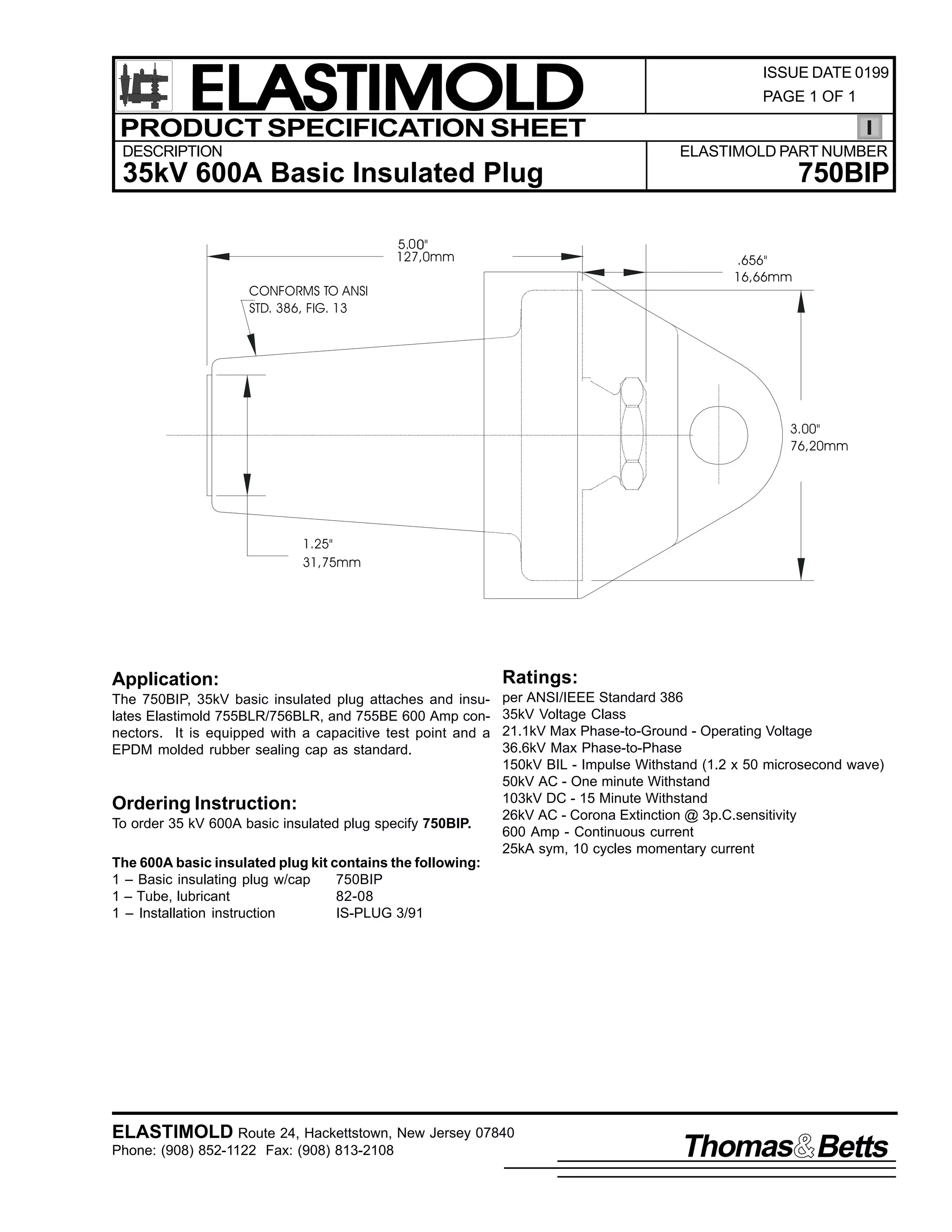
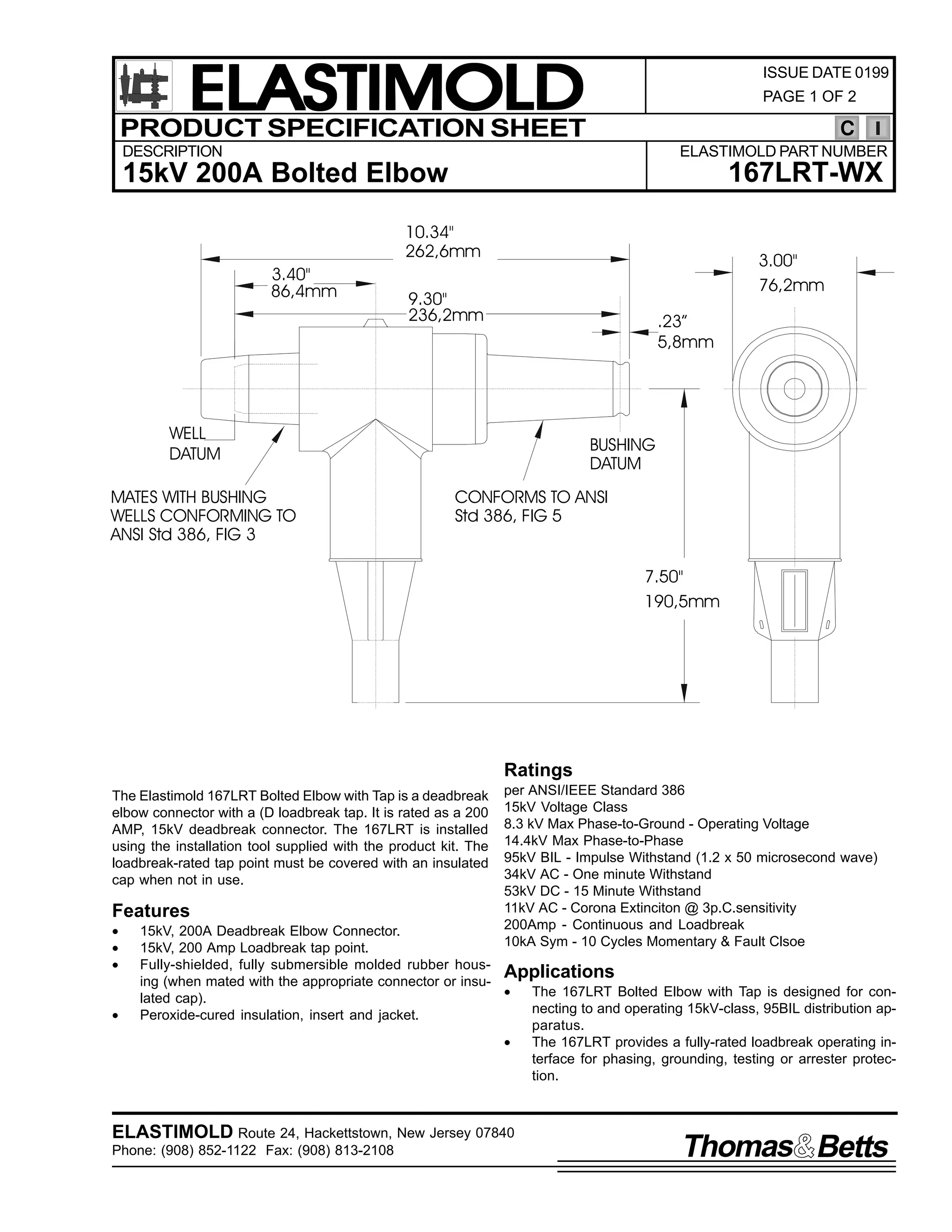
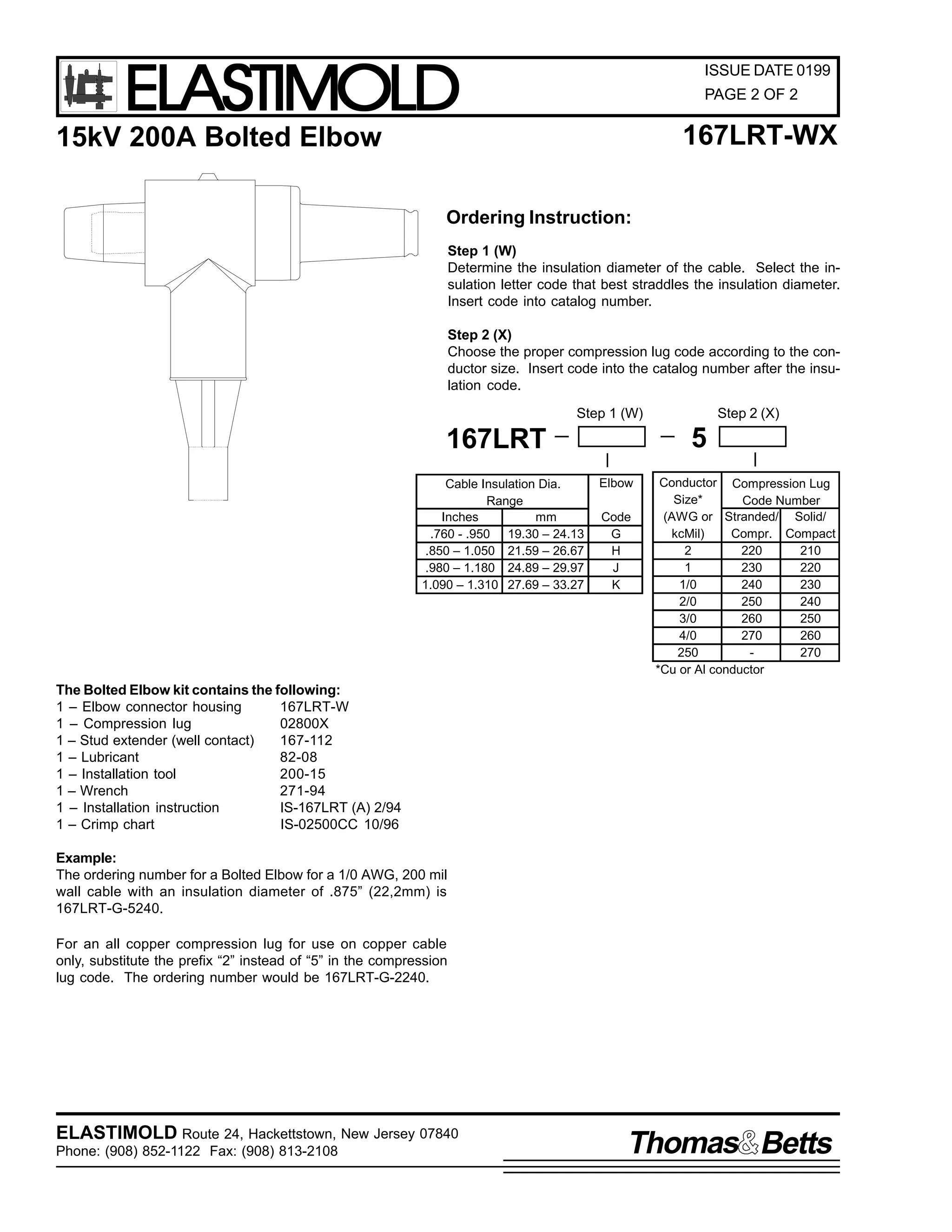
![9
,60 049:/57 +5HY $,
4 )HEUXDU 4<<7
3DJH 4 RI 9
,QVWDOODWLRQ ,QVWUXFWLRQV
49:/57
/2$'%5($. %86+,1* 7$3
&217(176=
%XVKLQJ 7DS +RXVLQJ/ &RPSUHVVLRQ /XJ/ 6RFNHW &RQWDFW/ :UHQFKHV/ /XEULFDQW +'R 1RW 6XEVWLWXWH,/
:HOO &RQWDFW/ ,QVWDOODWLRQ 7RRO/ ,QVWDOODWLRQ22SHUDWLQJ ,QVWUXFWLRQ1
7KH 49:/57 LV GHVLJQHG WR WHUPLQDWH 8' FDEOH KDYLQJ FRQFHQWULF QHXWUDO DQG H[WUXGHG LQVXODWLRQ VKLHOGLQJ1 7KH EXVKLQJ
SURYLGHV DQ RSHUDWLQJ LQWHUIDFH IRU FRQQHFWLQJ RI DQ (ODVWLPROG 48N9 FODVV +;16N9 SKDVH00WR00JURXQG DQG 4717N9
SKDVH00WR00SKDVH, 533DPSHUH ORDGEUHDN HOERZ RU DFFHVVRU GHYLFH1 :KHQ RWKHU WSHV RI 8' FDEOH DUH WR EH WHUPLQDWHG DQ
DSSURSULDWH (ODVWLPROG FDEOH VKLHOG RU JURXQGLQJ GHYLFH PXVW EH XVHG1
'$1*(5
$OO DSSDUDWXV PXVW EH GH00HQHUJL]HG GXULQJ LQVWDOODWLRQ
RU UHPRYDO RI SDUW+V,1
'R QRW WRXFK RU PRYH HQHUJL]HG SURGXFWV E KDQG1
([FHVV GLVWRUWLRQ RI WKH DVVHPEOHG SURGXFW PD UHVXOW
LQ LWV IDLOXUH1
,QVSHFW SDUWV IRU GDPDJH/ UDWLQJ DQG FRPSDWLELOLW ZLWK
PDWLQJ SDUWV1
7KLV SURGXFW VKRXOG EH LQVWDOOHG RQO E FRPSHWHQW
SHUVRQQHO WUDLQHG LQ JRRG VDIHW SUDFWLFHV LQYROYLQJ
KLJK YROWDJH HOHFWULFDO HTXLSPHQW1 7KHVH LQVWUXFWLRQV
DUH QRW LQWHQGHG DV D VXEVWLWXWH IRU DGHTXDWH WUDLQLQJ RU
H[SHULHQFH LQ VXFK VDIHW SUDFWLFHV1
7KHVH LQVWUXFWLRQV GR QRW DWWHPSW WR SURYLGH IRU HYHU
SRVVLEOH FRQWLQJHQF1
)DLOXUH WR IROORZ WKHVH LQVWUXFWLRQV ZLOO UHVXOW LQ GDPDJH
WR WKH SURGXFW DQG VHULRXV RU IDWDO LQMXU1
7KLV SURGXFW LV VXSSOLHG ZLWK D SURWHFWLYH VKLSSLQJ
FRYHU1 5HPRYH WKH VKLSSLQJ FRYHU DQG UHSODFH ZLWK WKH
DSSURSULDWH +9 LQVXODWHG FDS RU FRQQHFWRU EHIRUH
VXEPHUJLQJ RU HQHUJL]LQJ WKH FLUFXLW1
)25 025( ,1)250$7,21 21 3$576/ ,167$//$7,21 5$7,1*6 $1' &203$7,%,/,7</ &$// 7+( 1($5(67 (/$67,02/' 2)),&(1
,03257$17
41 &KHFN FRQWHQWV RI SDFNDJH WR LQVXUH WKH DUH FRPSOHWH
DQG XQGDPDJHG1
51 &KHFN DOO FRPSRQHQWV WR LQVXUH SURSHU ILW ZLWK FDEOH
DQG2RU PDWLQJ SURGXFWV1
61 5HDG HQWLUH LQVWDOODWLRQ LQVWUXFWLRQV EHIRUH VWDUWLQJ1
71 +DYH DOO UHTXLUHG WRROV DW KDQG DQG PDLQWDLQ FOHDQOLQHVV
WKURXJKRXW WKH SURFHGXUH1
:UHQFK
,QVWDOODWLRQ 7RRO
:HOO
&RQWDFW
6RFNHW &RQWDFW
&RPSUHVVLRQ /XJ
*URXQGLQJ (H
$66(0%/(' %86+,1* 7$3
,60 049:/57 +5HY $,
4 )HEUXDU 4<<7
3ULQWHG LQ 8161$1
5RXWH 57/ +DFNHWWVWRZQ/ 1HZ -HUVH 3:;73 86$
+<3;,;850 04455 )$;= +<3;,;460 05397
$ 'LYLVLRQ RI $PHUDFH &RUSRUDWLRQ1](https://image.slidesharecdn.com/elastimold-140130102426-phpapp02/75/Elastimold-Connectors-Loadbreak-Deadbreak-Elbow-Bolted-Tee-Connectors-HV-MV-700-Series-345-2048.jpg)
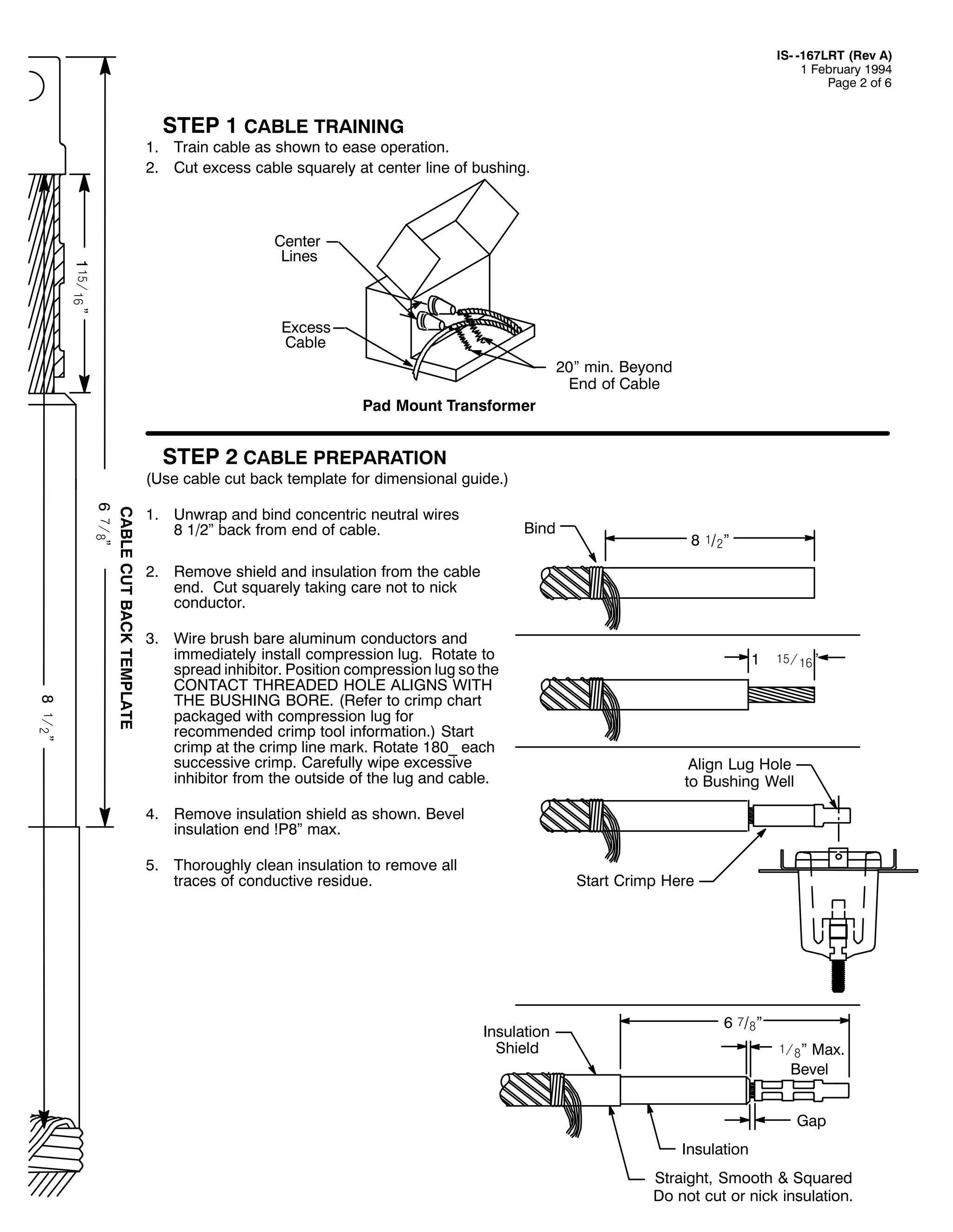
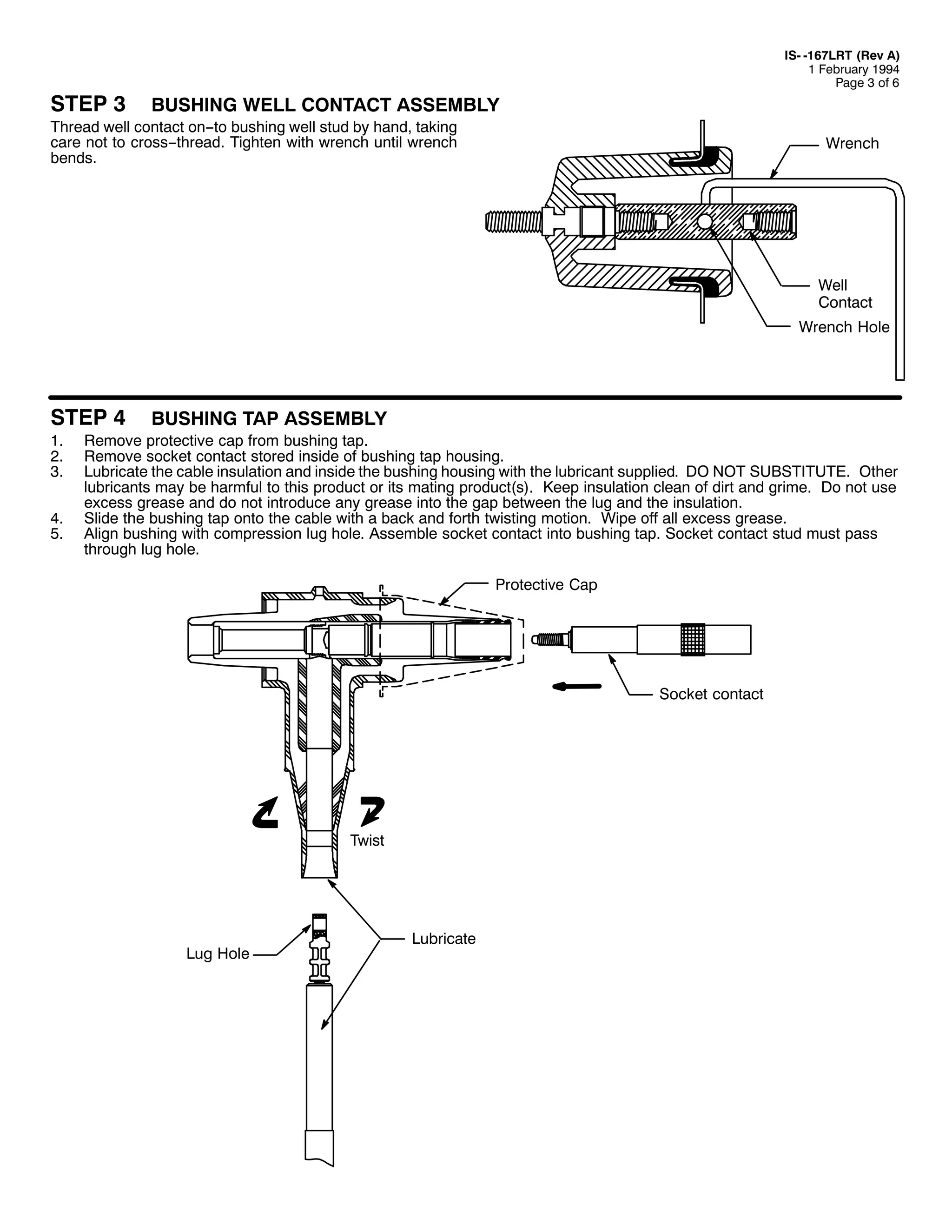
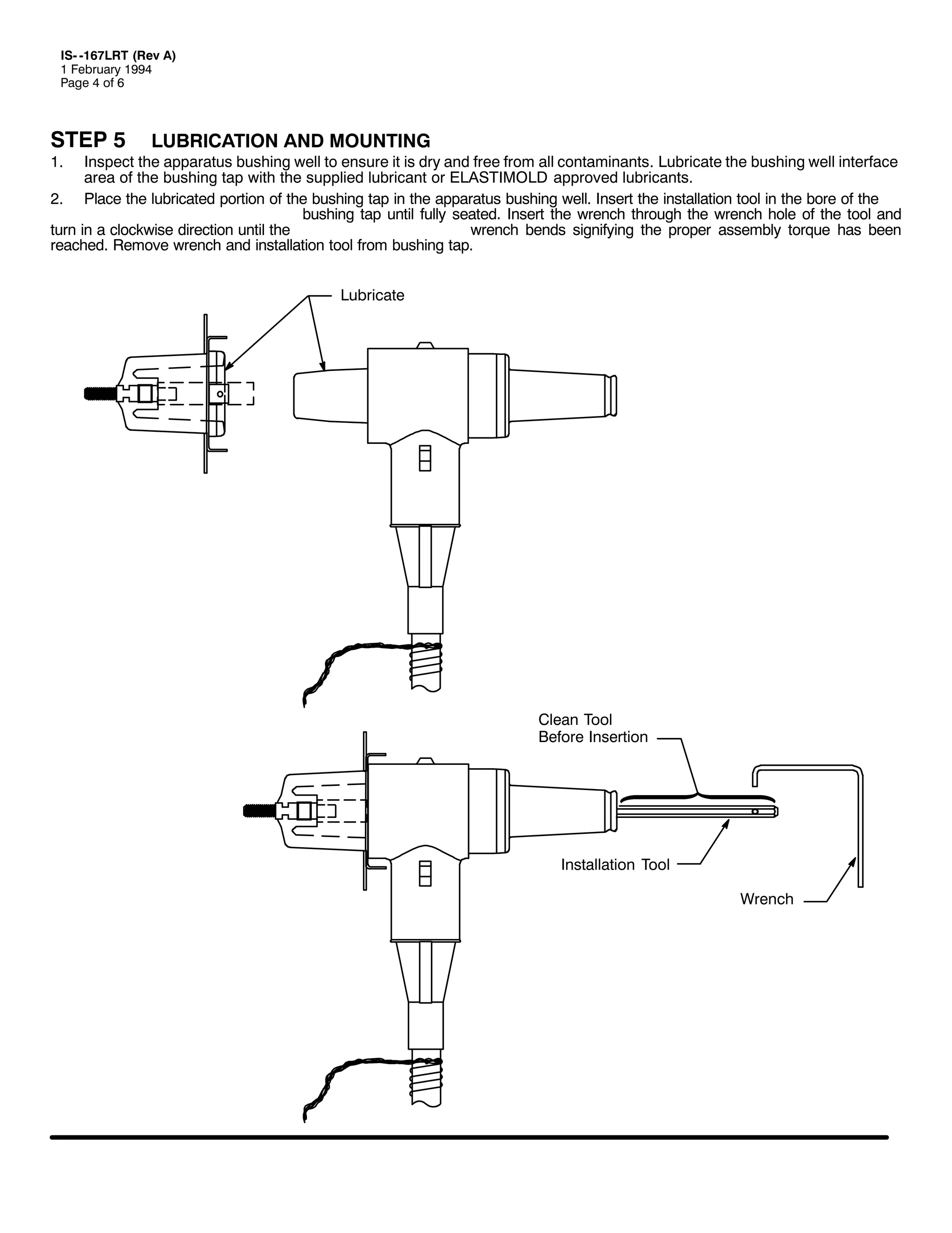
![67(3 9
41
51
,60 049:/57 +5HY $,
4 )HEUXDU 4<<7
3DJH 8 RI 9
&21&(175,& 1(875$/ &211(&7,21
,QVHUW RQH HQG RI D 1R1 47 $:* +518PP, FRSSHU ZLUH RU HTXLYDOHQW WKURXJK WKH JURXQGLQJ HH RQ WKH EXVKLQJ WDS1 7ZLVW WLJKW
WDNLQJ FDUH QRW WR GDPDJH HH1
7ZLVW QHXWUDO ZLUHV DQG FRQQHFW WR JURXQG XVLQJ DSSURSULDWH FRQQHFWRU1
*URXQGLQJ (H
67(3 :
7KRURXJKO ZLSH WKH EXVKLQJ WDS LQWHUIDFH FOHDQ RI DQ FRQWDPLQDQWV DQG DSSO D OLJKW/ XQLIRUP FRDW RI VXSSOLHG OXEULFDQW/
ZRUNLQJ WKRURXJKO LQWR VXUIDFH1 &$87,21= (;&(66 /8%5,&$17 PD SUHYHQW D ORDGEUHDN HOERZ IURP EHLQJ IXOO VHDWHG LQ
WKH µORFNHG RQµ SRVLWLRQ1 ,QVWDOO WKH PDWLQJ SURGXFWV WR WKH EXVKLQJ WDS IROORZLQJ WKH LQVWUXFWLRQV VXSSOLHG ZLWK WKH PDWLQJ
SURGXFWV1 ,I WKH EXVKLQJ WDS LV QRW WR EH LPPHGLDWHO PDWHG ZLWK DQ HOERZ FRQQHFWRU/ LQVXODWHG FDS RU JURXQGLQJ HOERZ FRQQHFWRU/
UHSODFH WKH VKLSSLQJ FDS1 'R QRW HQHUJL]H RU VXEPHUJH WKH DSSDUDWXV ZLWK WKH VKLSSLQJ FDS RQ WKH EXVKLQJ WDS1 7KLV LV D
SURWHFWLYH FDS RQO ZKLFK LV QRW LQVXODWHG RU ZDWHU WLJKW DQG RQO LQWHQGHG WR NHHS WKH EXVKLQJ WDS VXUIDFHV FOHDQ GXULQJ KDQGOLQJ
DQG LQVWDOODWLRQ1
&OHDQ %XVKLQJ &RQQHFWRU ,QWHUIDFH
DQG /XEULFDWH 7KRURXJKO
,QVXODWHG &DS
RU (OERZ](https://image.slidesharecdn.com/elastimold-140130102426-phpapp02/75/Elastimold-Connectors-Loadbreak-Deadbreak-Elbow-Bolted-Tee-Connectors-HV-MV-700-Series-349-2048.jpg)
![,60 049:/57 +5HY $,
4 )HEUXDU 4<<7
3DJH 9 RI 9
23(5$7,1* ,16758&7,216
%HIRUH /RDGPDNH RU /RDGEUHDN 2SHUDWLRQ=
/RDGEUHDN FRQQHFWRUV PXVW EH RSHUDWHG ZLWK DQ HLJKW IRRW ORQJ/ IXOO LQVXODWHG µKRWVWLFNµ WSH RI WRRO1
5HPRYH )OXLG ,QMHFWLRQ RU 9ROWDJH 7HVW &DS DQG LQVWDOO ,QVXODWHG &DS IROORZLQJ LQVWUXFWLRQV SDFNDJHG ZLWK WKHVH SDUWV1
$UHD PXVW EH FOHDU RI REVWUXFWLRQV RU FRQWDPLQDQWV WKDW ZRXOG LQWHUIHUH ZLWK WKH RSHUDWLRQ RI WKH FRQQHFWRU1 7KLV SRVLWLRQ VKRXOG DOORZ RX WR HVWDEOLVK ILUP IRRWLQJ
DQG HQDEOH RX WR JUDVS WKH KRWVWLFN WRRO VHFXUHO/ PDLQWDLQLQJ SRVLWLYH FRQWURO RYHU WKH PRYHPHQW RI WKH ORDGEUHDN FRQQHFWRU EHIRUH/ GXULQJ DQG GLUHFWO DIWHU WKH
RSHUDWLQJ VHTXHQFH1 %HFDXVH RI WKH FRQWURO/ VSHHG DQG IRUFH UHTXLUHG WR HQJDJH RU GLVHQJDJH WKH HOERZ/ FHUWDLQ RSHUDWLQJ SRVLWLRQV DUH PRUH DGYDQWDJHRXV WKDQ
RWKHUV1 ,I WKHUH LV VRPH TXHVWLRQ DV WR SURSHU RSHUDWLQJ SRVLWLRQ/ LW LV UHFRPPHQGHG WKDW WKH FRQQHFWRUV EH RSHUDWHG GH00HQHUJL]HG1 'R QRW FRQQHFW WZR GLIIHUHQW
SKDVHV RI D PXOWLSOH00SKDVH VVWHP1 %HIRUH FORVLQJ D VLQJOH00SKDVH ORRS/ PDNH FHUWDLQ ERWK HQGV RI WKH ORRS DUH WKH VDPH SKDVH1
/2$'0$.( 23(5$7,21
127(= &KHFN DSSURSULDWH DFFHVVRU GHYLFH RSHUDWLQJ LQVWUXFWLRQV WR EH VXUH WKDW WKH GHYLFH LV UDWHG IRU HQHUJL]HG RSHUDWLRQ1
41
51
61
71
81
$UHD PXVW EH FOHDU RI REVWUXFWLRQV RU FRQWDPLQDQWV WKDW ZRXOG LQWHUIHUH ZLWK WKH RSHUDWLRQ RI WKH FRQQHFWRU1
,Q SUHSDULQJ EXVKLQJ IRU HOERZ FRQQHFWRU/ UHPRYH LQVXODWHG FDS E DWWDFKLQJ KRWVWLFN WRRO WR WKH LQVXODWHG FDS SXOOLQJ HH/ DQG IROORZLQJ WKH LQVWUXFWLRQV
IRU WKLV DFFHVVRU/ UHPRYH IURP EXVKLQJ1
6HFXUHO IDVWHQ D KRWVWLFN WR WKH ORDGEUHDN FRQQHFWRU SXOOLQJ HH1
$IWHU HVWDEOLVKLQJ ILUP IRRWLQJ DQG SRVLWLYH FRQWURO RI WKH HOERZ FRQQHFWRU/ ZLWKGUDZ WKH HOERZ IURP WKH DFFHVVRU GHYLFH RQ WKH DSSDUDWXV SDUNLQJ VWDQG
ZLWK D IDVW/ VWUDLJKW/ ILUP PRWLRQ EHLQJ FDUHIXO QRW WR SODFH WKH HOERZ FRQQHFWRU QHDU D JURXQG SODQH1
3ODFH WKH HOERZ FRQQHFWRU UHFHSWDFOH DUHD RYHU WKH EXVKLQJ SOXJ/ LQVHUWLQJ WKH HOERZ PDOH FRQWDFW +DUF IROORZHU SRUWLRQ, LQWR WKH EXVKLQJ XQWLO WKH ILUVW VOLJKW
UHVLVWDQFH LV IHOW1 5HVLVWDQFH LV IHOW ZKHQ WKH DUF IROORZHU SRUWLRQ RI WKH PDOH FRQWDFW ILUVW PHHWV WKH IHPDOH FRQWDFW RI WKH EXVKLQJ +DW WKLV SRLQW WKH FRQWDFWV
DUH DSSUR[LPDWHO 5µ DSDUW,1
127(= '2 127 +2/' ,1 7+,6 326,7,21 %87 ,00(',$7(/< 386+ 7+( (/%2: +20( :,7+ $ )$67/ ),50/ 675$,*+7 027,21/ ZKLFK ZLOO
HQJDJH WKH LQWHUQDO ORFN RQ WKH HOERZ DQG EXVKLQJ LQWHUIDFH1
$SSO VXIILFLHQW IRUFH WR HQJDJH WKH LQWHUQDO ORFN RQ WKH HOERZ FRQQHFWRU DQG EXVKLQJ LQWHUIDFH1
)DXOW &ORVH
41
51
,W LV QRW UHFRPPHQGHG WKDW RSHUDWLRQV EH PDGH RQ NQRZQ IDXOWV1
,I D IDXOW LV H[SHULHQFHG/ ERWK WKH HOERZ FRQQHFWRU DQG WKH EXVKLQJ PXVW EH UHSODFHG1
41
3ODFH GHVLUHG DFFHVVRU GHYLFH RQ DSSDUDWXV SDUNLQJ VWDQG1
127(= 5HIHU WR DSSURSULDWH RSHUDWLQJ LQVWUXFWLRQV IRU DFFHVVRU GHYLFH WR EH XVHG1 %H FHUWDLQ LW LV UDWHG IRU HQHUJL]HG RSHUDWLRQ1
)LUPO WLJKWHQ D KRWVWLFN WR WKH ORDGEUHDN FRQQHFWRU SXOOLQJ HH1
:LWKRXW H[HUWLQJ DQ SXOOLQJ IRUFH/ VOLJKWO URWDWH WKH FRQQHFWRU LQ RUGHU WR EUHDN VXUIDFH IULFWLRQ SULRU WR GLVFRQQHFWLRQ1
:LWKGUDZ WKH FRQQHFWRU IURP WKH EXVKLQJ ZLWK D IDVW/ ILUP/ VWUDLJKW PRWLRQ/ EHLQJ FDUHIXO QRW WR SODFH WKH FRQQHFWRU QHDU D JURXQG SODQH1
3ODFH FRQQHFWRU RQ DSSURSULDWH DFFHVVRU GHYLFH/ IROORZLQJ WKH RSHUDWLQJ LQVWUXFWLRQV IRU WKDW DFFHVVRU1
/2$'%5($. 23(5$7,21
51
61
71
81
5RXWH 57/ +DFNHWWVWRZQ/ 1HZ -HUVH 3:;73 86$
+<3;,;850 04455 )$;= +<3;,;850 0948;
$ 'LYLVLRQ RI $PHUDFH &RUSRUDWLRQ](https://image.slidesharecdn.com/elastimold-140130102426-phpapp02/75/Elastimold-Connectors-Loadbreak-Deadbreak-Elbow-Bolted-Tee-Connectors-HV-MV-700-Series-350-2048.jpg)
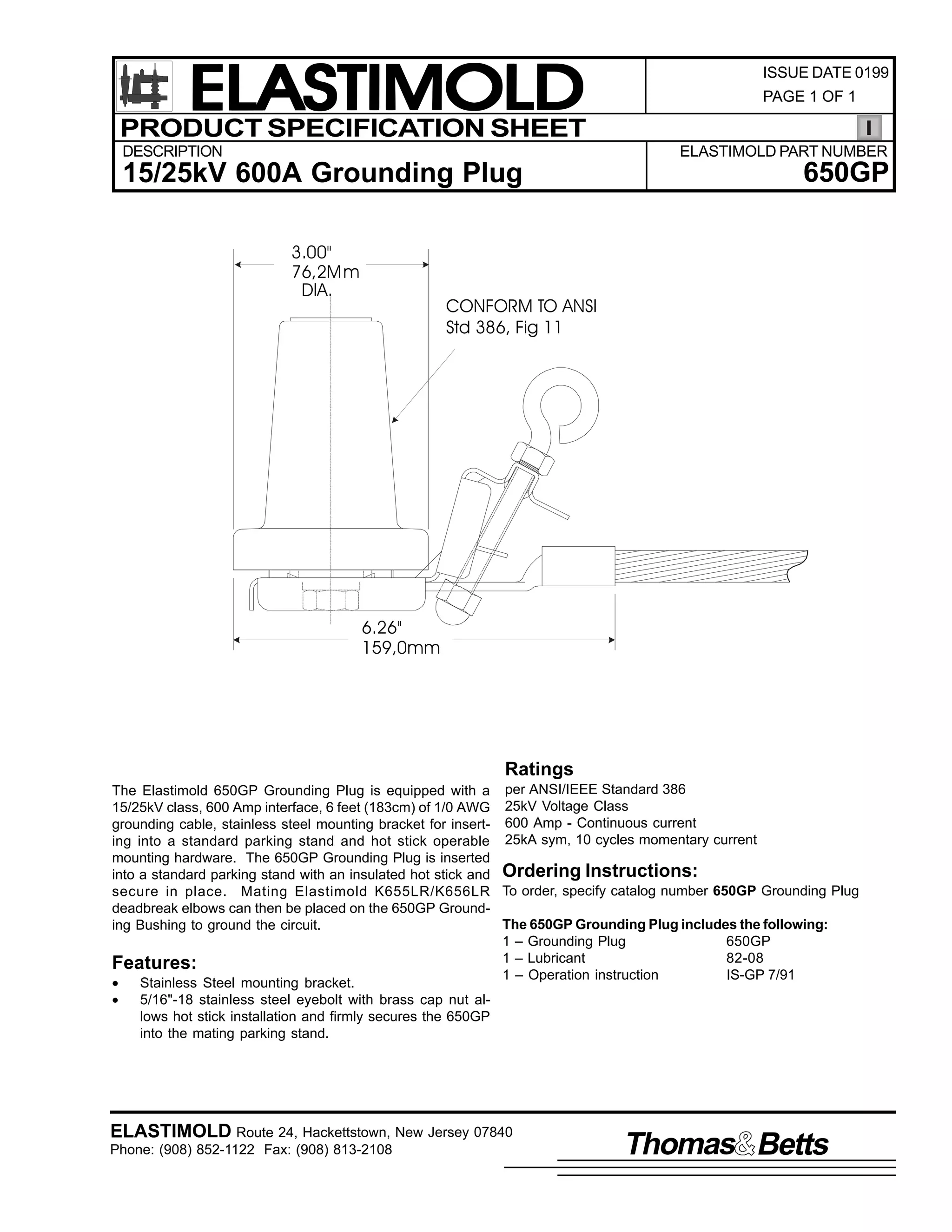
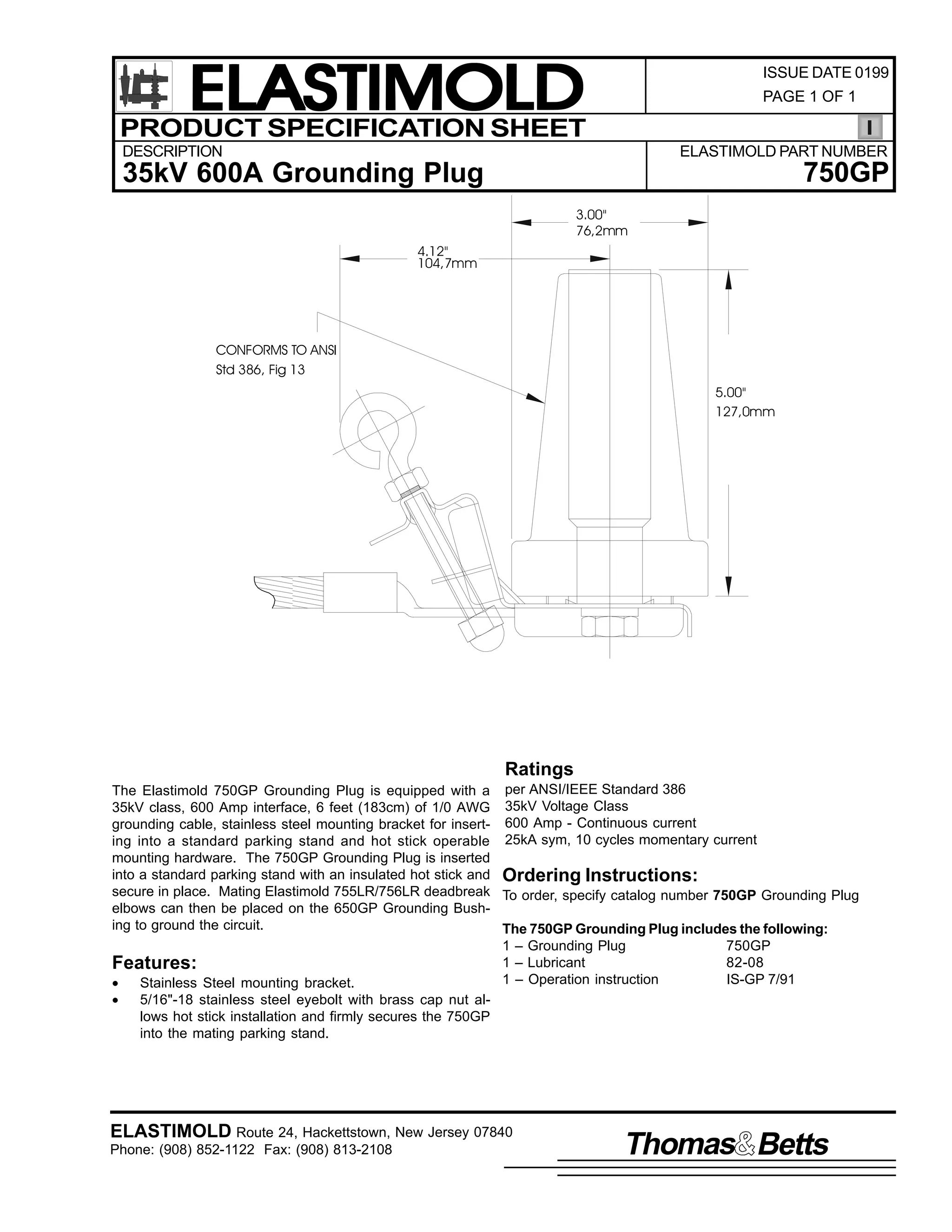
![9
,60 0*3
63 -XO 4<<4
3DJH 4
2SHUDWLQJ ,QVWUXFWLRQV
983*3 DQG :83*3
*URXQGLQJ 3OXJ
&217(176=
*URXQGLQJ 3OXJ +FRPSOHWH ZLWK PRXQWLQJ KDUGZDUH,/ /XEULFDQW/ 2SHUDWLQJ ,QVWUXFWLRQV1
7KH *URXQGLQJ 3OXJ LV GHVLJQHG WR JURXQG D FDEOH WHUPLQDWHG ZLWK D 933 DPSHUH HOERZ1
'$1*(5
$OO DSSDUDWXV PXVW EH GH0 0HQHUJL]HG GXULQJ LQVWDOODWLRQ
RU UHPRYDO RI SDUW+V,1
SHUVRQQHO WUDLQHG LQ JRRG VDIHW SUDFWLFHV LQYROYLQJ
KLJK YROWDJH HOHFWULFDO HTXLSPHQW1 7KHVH LQVWUXFWLRQV
DUH QRW LQWHQGHG DV D VXEVWLWXWH IRU DGHTXDWH WUDLQLQJ RU
'R QRW WRXFK RU PRYH HQHUJL]HG FDEOHV DQG2RU SURGXFWV
H[SHULHQFH LQ VXFK VDIHW SUDFWLFHV1
E KDQG1
7KHVH LQVWUXFWLRQV GR QRW DWWHPSW WR SURYLGH IRU HYHU
SRVVLEOH FRQWLQJHQF1
([FHVV GLVWRUWLRQ RI WKH DVVHPEOHG SURGXFW PD UHVXOW
)DLOXUH WR IROORZ WKHVH LQVWUXFWLRQV FRXOG UHVXOW LQ GDP0
LQ LWV IDLOXUH1
DJH WR WKH SURGXFW DQG VHULRXV RU IDWDO LQMXU1
,QVSHFW SDUWV IRU GDPDJH/ UDWLQJ DQG FRPSDWLELOLW ZLWK
7KLV SURGXFW LV VXSSOLHG ZLWK D SURWHFWLYH VKLSSLQJ FDS1
PDWLQJ SDUWV1
5HPRYH WKLV VKLSSLQJ FDS DQG UHSODFH ZLWK WKH DSSUR0
SULDWH +9 LQVXODWHG FDS RU FRQQHFWRU EHIRUH VXEPHUJ0
7KLV SURGXFW VKRXOG EH LQVWDOOHG RQO E FRPSHWHQW
LQJ RU HQHUJL]LQJ WKH FLUFXLW1
)25 025( ,1)250$7,21 21 3$576/ ,167$//$7,21 5$7,1*6 $1' &203$7,%,/,7</ &$// 7+( 1($5(67 (/$60
7,02/' 2)),&(1
,03257$17
41 &KHFN FRQWHQWV RI SDFNDJH WR LQVXUH WKH DUH FRP0 0
SOHWH DQG XQGDPDJHG1
61 5HDG HQWLUH LQVWDOODWLRQ LQVWUXFWLRQV EHIRUH VWDUWLQJ1
51 &KHFN DOO FRPSRQHQWV WR LQVXUH SURSHU ILW ZLWK FDEOH
DQG2RU PDWLQJ SURGXFWV1
71 +DYH DOO UHTXLUHG WRROV DW KDQG DQG PDLQWDLQ FOHDQOL0 0
QHVV WKURXJKRXW WKH SURFHGXUH1
67(3 4
7R 6VWHP *URXQG
&RQQHFW WKH IOH[LEOH OHDG RI WKH JURXQGLQJ SOXJ WR VVWHP
JURXQG OHDYLQJ HQRXJK VODFN WR RSHUDWH ZLWK D KRWVWLFN1
(HEROW
&OHDQ WKH LQWHUIDFH RI WKH JURXQGLQJ SOXJ1 /XEULFDWH WKLV
VXUIDFH1 8VH RQO WKH VXSSOLHG OXEULFDQW RU (/$67,02/'
DSSURYHG OXEULFDQWV1 '2 127 68%67,787(1 2WKHU OXEUL0
FDQWV PD EH KDUPIXO WR WKLV SURGXFW DQG LWV PDWLQJ SURG0
XFWV1 $OZDV UHSODFH WKH SURWHFWLYH FDS ZKHQ WKH JURXQG0
LQJ SOXJ LV QRW LQ XVH1
/XEULFDWH
,60 0*3
63 -XO 4<<4
3ULQWHG LQ 8161$1
5RXWH 57/ +DFNHWWVWRZQ/ 1HZ -HUVH 3:;73 86$
+<3;,;850 04455 )$;= +<3;,;850 0948;](https://image.slidesharecdn.com/elastimold-140130102426-phpapp02/75/Elastimold-Connectors-Loadbreak-Deadbreak-Elbow-Bolted-Tee-Connectors-HV-MV-700-Series-353-2048.jpg)
![,60 0*3
63 -XO 4<<4
3DJH 5
67(3 5
$WWDFK KRWVWLFN WR WKH HH RI WKH JURXQGLQJ SOXJ FDUULDJH
DVVHPEO1 6OLGH FDUULDJH DVVHPEO LQWR SDUNLQJ VWDQG1
&DUULDJH $VVHPEO
7R 6VWHP
*URXQG
+RWVWLFN
3DUNLQJ 6WDQG
67(3 6
)ROORZ WKH DSSOLFDEOH LQVWUXFWLRQV IRU WKH +.,988/5 2:88/5 WR GHWHUPLQH WKDW WKH HOERZ FRQQHFWRU LV GH0 0HQHUJL]HG EHIRUH
UHPRYLQJ IURP WKH DSSDUDWXV EXVKLQJ1 5HPRYH HOERZ FRQQHFWRU IURP DSSDUDWXV EXVKLQJ DQG SODFH RQ JURXQGLQJ SOXJ1 '2
127 5(029( ,) (/%2: &211(&725 ,6 (1(5*,=('1
:$55$17<
7KLV SURGXFW ZLOO SHUIRUP ZLWKLQ WKH UHFRPPHQGHG RSHUDWLRQDO UDWLQJV ZKHQ LQVWDOOHG DQG RSHUDWHG LQ DFFRUGDQFH ZLWK DSSOLFDEOH LQVWUXFWLRQV1 $PHUDFH &RUSRUDWLRQ*V OLDELOLW LV OLPLWHG WR UHSODFHPHQW SDUWV
GHVLJQHG DQG PDQXIDFWXUHG E $PHUDFH ZKLFK DUH SURYHG WR EH GHIHFWLYH LQ ZRUNPDQVKLS RU PDWHULDO1 $OO VWDWHPHQWV/ WHFKQLFDO LQIRUPDWLRQ DQG UHFRPPHQGDWLRQV VXSSOLHG ZLWK WKH SURGXFW DUH EDVHG RQ
WHVWV EHOLHYHG WR EH UHOLDEOH/ EXW WKH DFFXUDF RU FRPSOHWHQHVV WKHUHRI LV QRW JXDUDQWHHG1 ,Q DGMXVWPHQW RI DQ FODLPV/ LQVSHFWLRQ RI WKH SDUWV DQG DSSOLFDWLRQ ZLOO EH UHTXLUHG1 $PHUDFH H[SUHVVO GLVFODLPV DQG
H[FOXGHV DOO RWKHU ZDUUDQWLHV H[SUHVV RU LPSOLHG/ LQFOXGLQJ ZLWKRXW OLPLWDWLRQ WKH ZDUUDQWLHV RI PHUFKDQWDELOLW DQG RI ILWQHVV IRU D SDUWLFXODU SXUSRVH/ DQG DOVR GLVFODLPV DQG H[FOXGHV DOO FRQVHTXHQWLDO DQG
LQFLGHQWDO GDPDJHV1 7KLV ZDUUDQW LV HIIHFWLYH IRU WZR +5, HDUV IURP GDWH RI VKLSPHQW1 +:0 0((5,1
5RXWH 57/ +DFNHWWVWRZQ/ 1HZ -HUVH 3:;73 86$
+<3;,;850 04455 )$;= +<3;,;850 0948;](https://image.slidesharecdn.com/elastimold-140130102426-phpapp02/75/Elastimold-Connectors-Loadbreak-Deadbreak-Elbow-Bolted-Tee-Connectors-HV-MV-700-Series-354-2048.jpg)
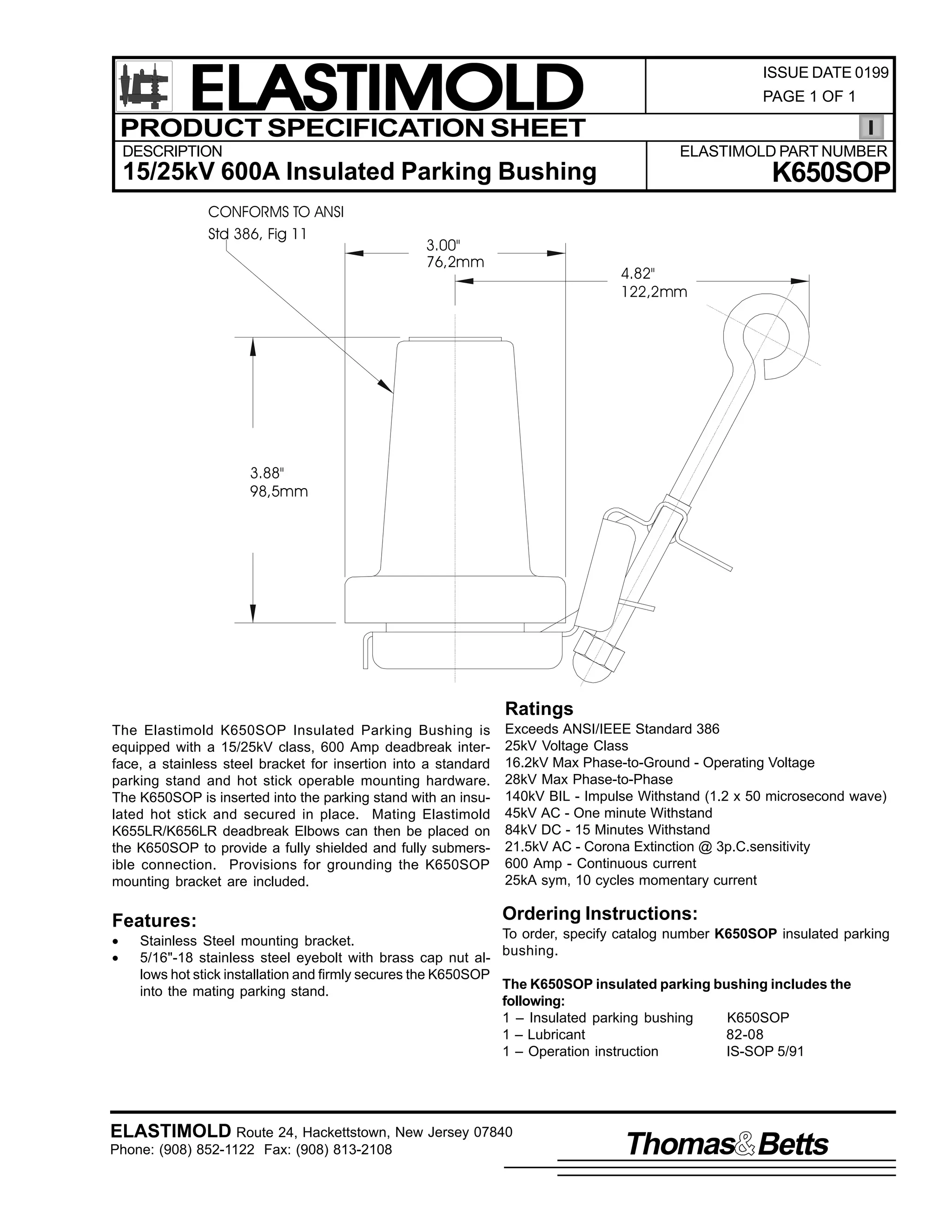
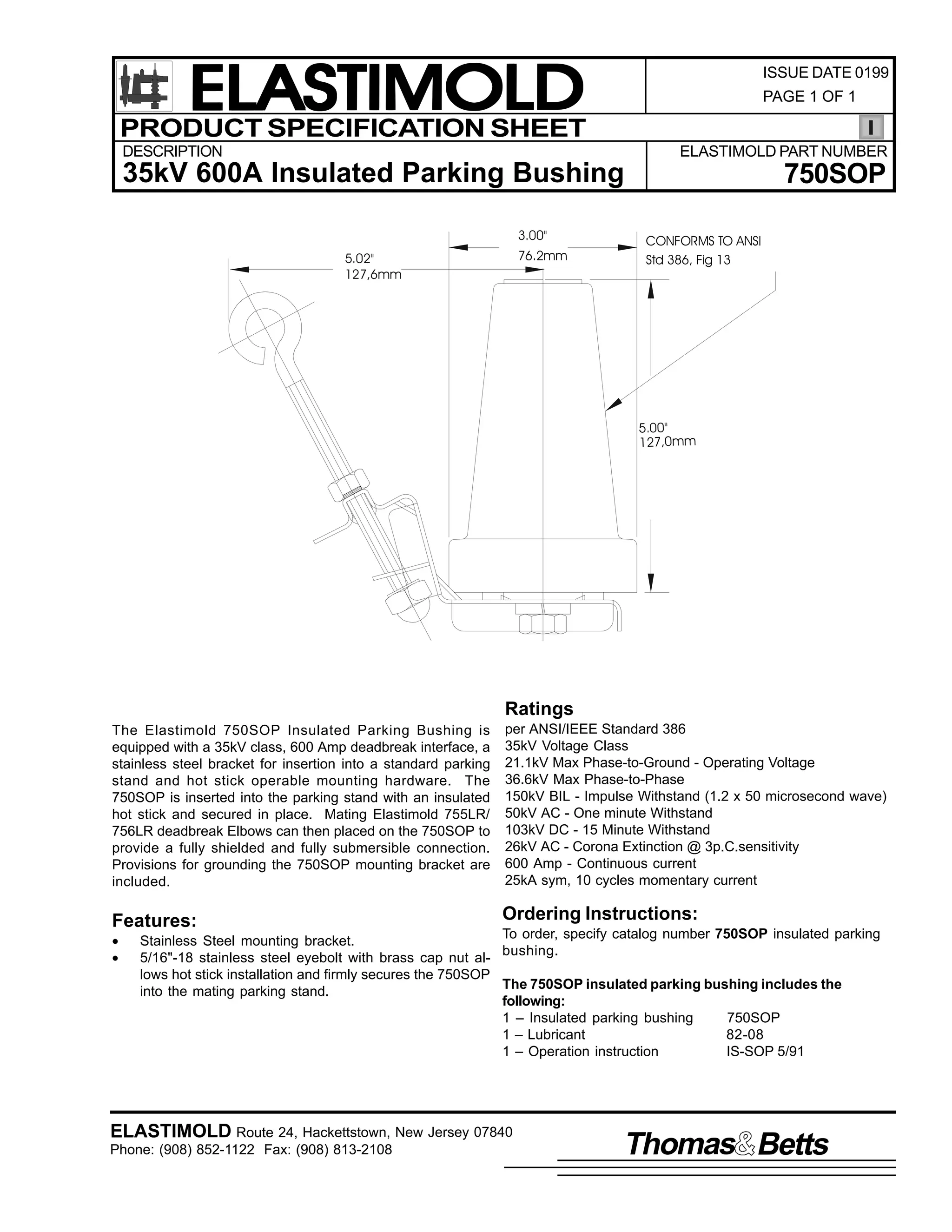
![9
,60 0623
64 0D 4<<4
3DJH 4
2SHUDWLQJ ,QVWUXFWLRQV
983623/ .983623/ DQG :83623
6WDQG0 02II 3OXJV
&217(176= 40 06WDQG RII SOXJ ZLWK VWDLQOHVV VWHHO PRXQWLQJ KDUGZDUH/ /XEULFDQW/ 40 0,QVWUXFWLRQ 6KHHW
7KH (ODVWLPROG 983623 .983623 DQG :83623 VWDQG0 0RII SOXJV DUH XVHG WR LVRODWH DQG (ODVWLPROG 988/5/ .988/5/ RU
/
/
:88/5 HOERZ FRQQHFWRU/ UHVSHFWLYHO1
127(= 7+( 67$1'0 02)) 3/8* 6+28/' $/:$<6 %( 0$7(' :,7+ (,7+(5 $1 ,168/$7(' &$3 +983623 $1'
.983623,/
$ %86+,1* &219(57(5/ 25 $1 (/%2: &211(&725 :+(1 127 ,1 86( 72 35(0
9(17 &217$0,1$7,21 2) 7+(
,17(5)$&(1
'$1*(5
$OO DSSDUDWXV PXVW EH GH0 0HQHUJL]HG GXULQJ LQVWDOODWLRQ
RU UHPRYDO RI SDUW+V,1
SHUVRQQHO WUDLQHG LQ JRRG VDIHW SUDFWLFHV LQYROYLQJ
KLJK YROWDJH HOHFWULFDO HTXLSPHQW1 7KHVH LQVWUXFWLRQV
DUH QRW LQWHQGHG DV D VXEVWLWXWH IRU DGHTXDWH WUDLQLQJ RU
'R QRW WRXFK RU PRYH HQHUJL]HG FDEOHV DQG2RU SURGXFWV
H[SHULHQFH LQ VXFK VDIHW SUDFWLFHV1
E KDQG1
7KHVH LQVWUXFWLRQV GR QRW DWWHPSW WR SURYLGH IRU HYHU
SRVVLEOH FRQWLQJHQF1
([FHVV GLVWRUWLRQ RI WKH DVVHPEOHG SURGXFW PD UHVXOW
)DLOXUH WR IROORZ WKHVH LQVWUXFWLRQV FRXOG UHVXOW LQ GDP0
LQ LWV IDLOXUH1
DJH WR WKH SURGXFW DQG VHULRXV RU IDWDO LQMXU1
,QVSHFW SDUWV IRU GDPDJH/ UDWLQJ DQG FRPSDWLELOLW ZLWK
7KLV SURGXFW LV VXSSOLHG ZLWK D SURWHFWLYH VKLSSLQJ FDS1
PDWLQJ SDUWV1
5HPRYH WKLV VKLSSLQJ FDS DQG UHSODFH ZLWK WKH DSSUR0
SULDWH +9 LQVXODWHG2VKLHOGHG GHDGHQG FDS RU FRQQHFWRU
7KLV SURGXFW VKRXOG EH LQVWDOOHG RQO E FRPSHWHQW
EHIRUH VXEPHUJLQJ RU HQHUJL]LQJ WKH FLUFXLW1
)25 025( ,1)250$7,21 21 3$576/ ,167$//$7,21 5$7,1*6 $1' &203$7,%,/,7</ &$// 7+( 1($5(67 (/$60
7,02/' 2)),&(1
,03257$17
41 &KHFN FRQWHQWV RI SDFNDJH WR LQVXUH LW LV FRPSOHWH
DQG XQGDPDJHG1
51 &KHFN DOO FRPSRQHQWV WR LQVXUH SURSHU ILW ZLWK FDEOH
DQG2RU PDWLQJ SURGXFWV1
61 5HDG HQWLUH LQVWDOODWLRQ LQVWUXFWLRQV EHIRUH VWDUWLQJ1
71 +DYH DOO UHTXLUHG WRROV DW KDQG DQG REVHUYH FOHDQOL0 0
QHVV WKURXJKRXW WKH SURFHGXUH1
67(3 4
/XEULFDWH WKH LQWHUIDFH ZLWK OXEULFDQW VXSSOLHG RU (/$67,02/' DSSURYHG OXEULFDQW1 '2 127 68%67,787(1 2WKHU OXEULFDQWV
PD EH KDUPIXO WR WKLV SURGXFW RU LWV PDWLQJ SURGXFWV1
(<(%2/7
,60 0623
64 0D 4<<4
3ULQWHG LQ 8161$1
/8%5,&$7(](https://image.slidesharecdn.com/elastimold-140130102426-phpapp02/75/Elastimold-Connectors-Loadbreak-Deadbreak-Elbow-Bolted-Tee-Connectors-HV-MV-700-Series-357-2048.jpg)
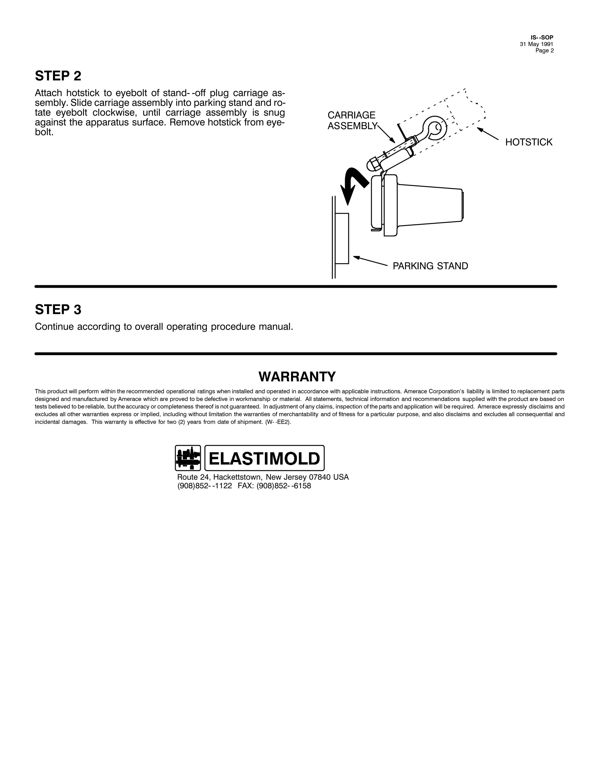
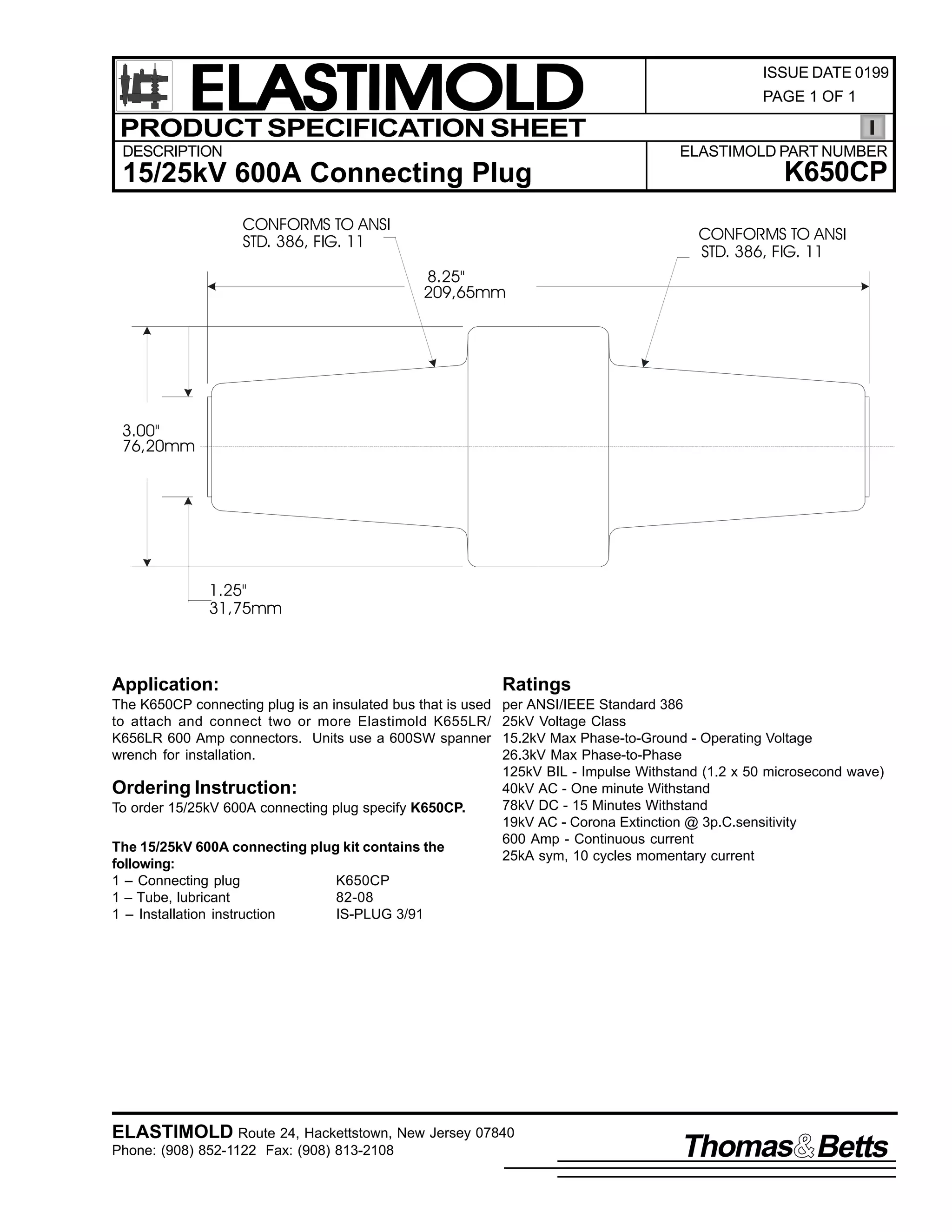
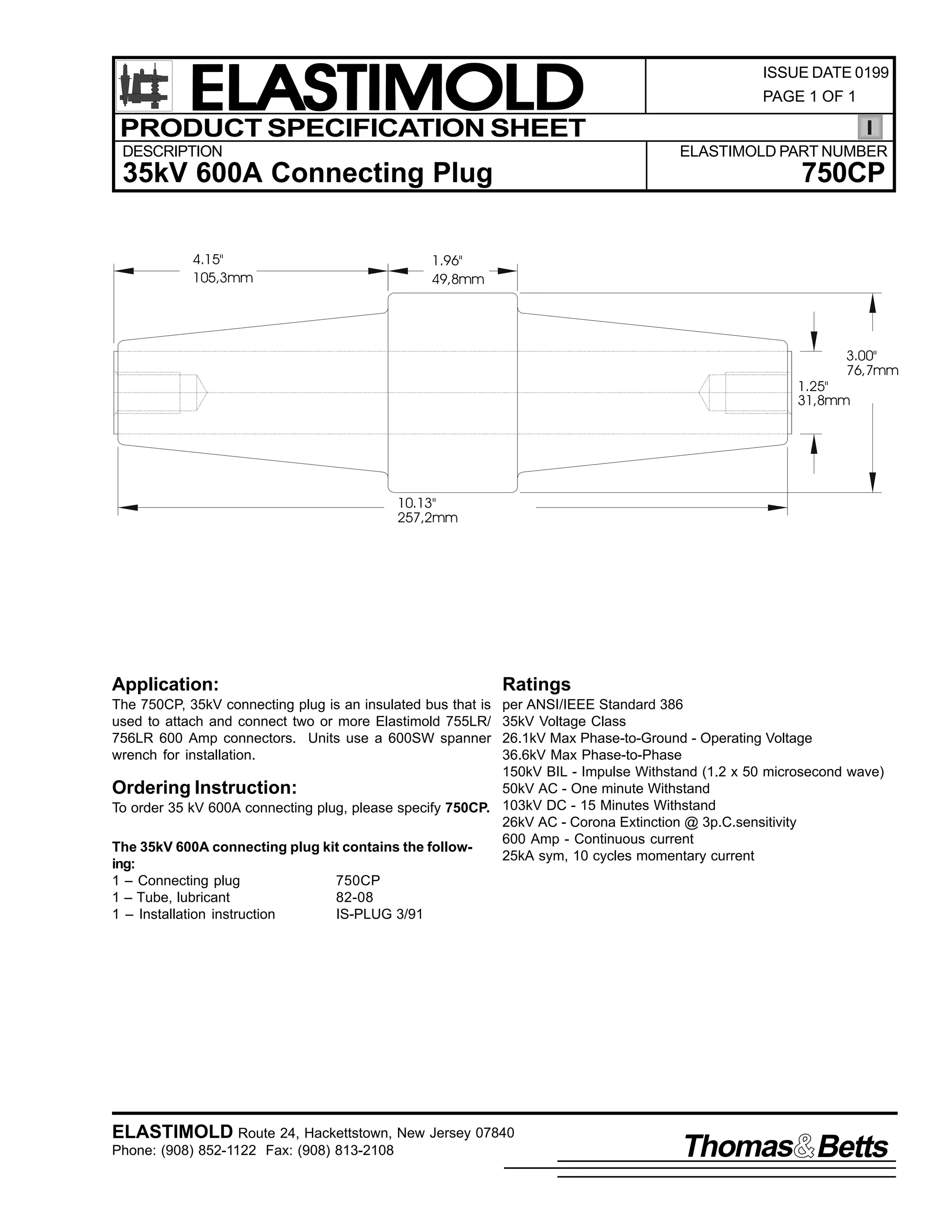
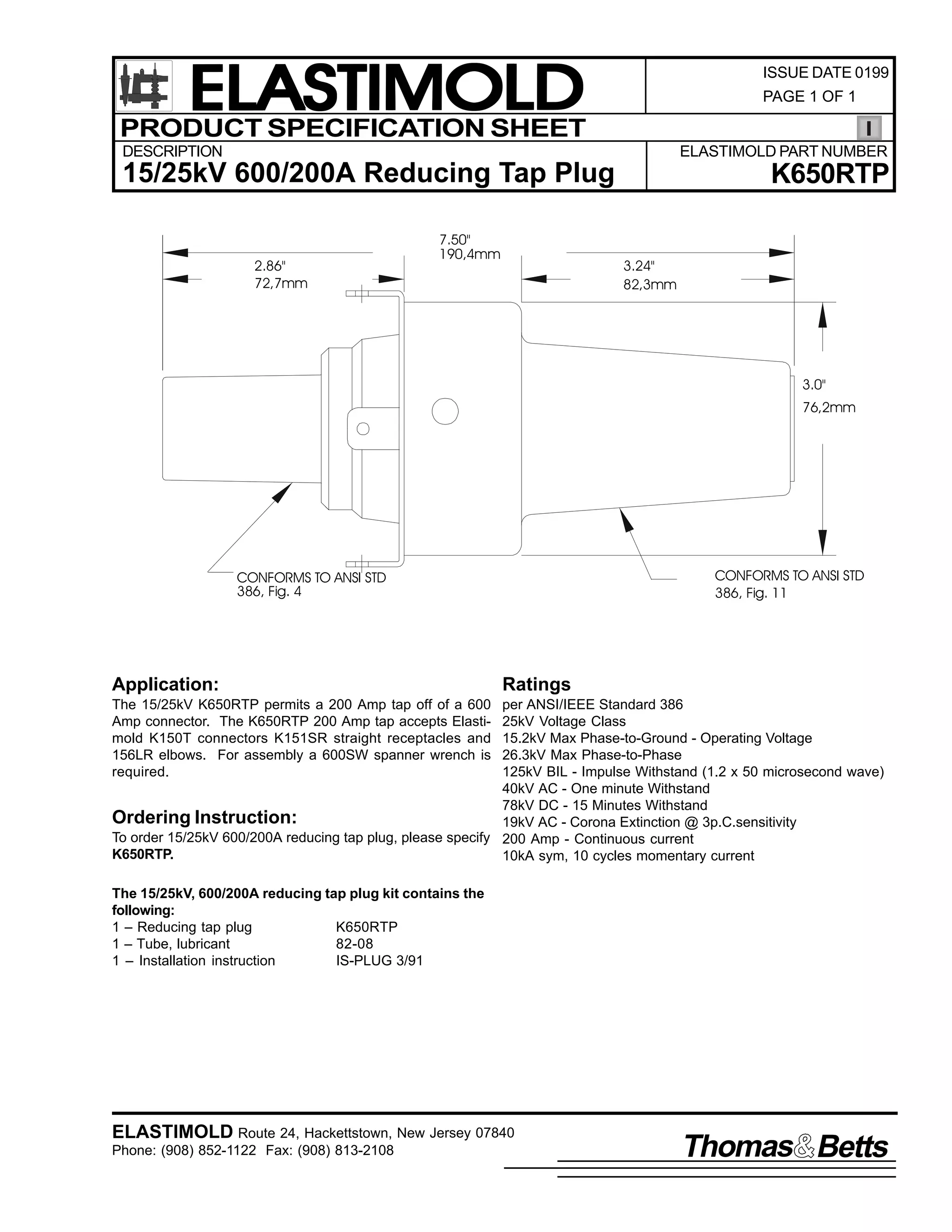
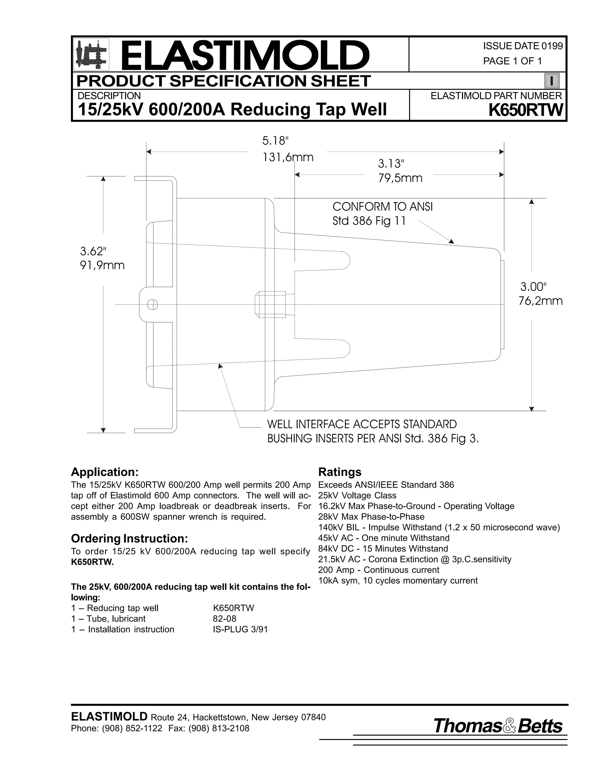


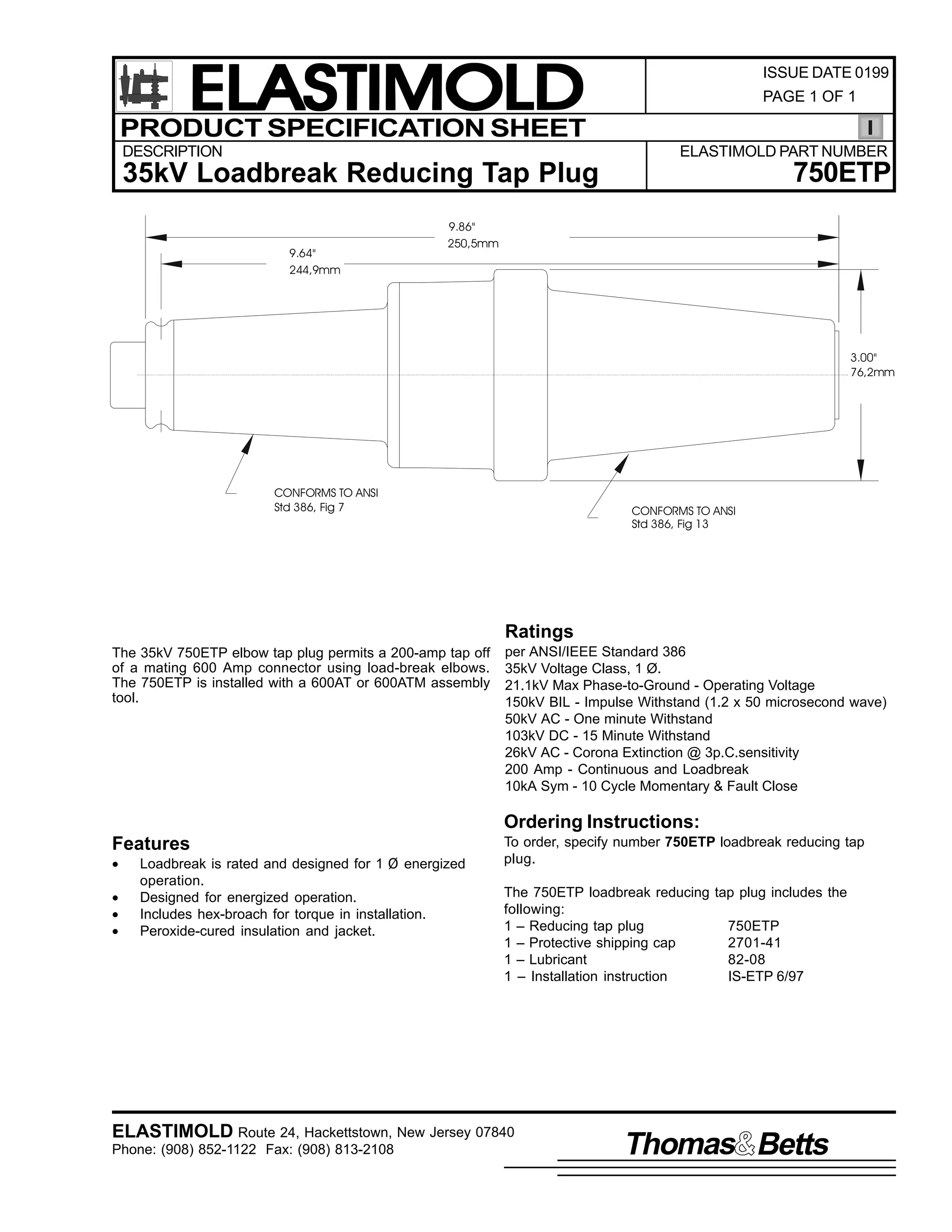
![9
,60 0(73
-XQH 4<<:
3DJH 4 RI 6
,QVWDOODWLRQ ,QVWUXFWLRQV
(73
(OERZ 7DS 3OXJ
&217(176= 7DS 3OXJ/ /XEULFDQW +'2 127 68%67,787(,/ 6WXG +LI DSSOLFDEOH,/ ,QVWDOODWLRQ ,QVWUXFWLRQV1
:$51,1*= 7+(
$9$,/$%/( )$8/7 &855(17 0867 %( /,0,7(' 72 43/333 $03(5(6 :+(1 86,1* 7+,6 352'8&71
7KH (73 LV GHVLJQHG WR SURYLGH D 533 DPSHUH ORDGEUHDN WDS DW VVWHP YROWDJH DV LQGLFDWHG RQ WKH (731
:$51,1*= 7+( )2//2:,1* 5$7,1*6 $33/< 72 7+,6 352'8&7=
9332<33 $PSHUH 'HDGEUHDN ,QWHUIDFH 0 0 933 RU <33 DPSHUHV ORDG FXUUHQW DQG 58/333 DPSHUHV VKRUW FLUFXLW
FXUUHQW IRU 43 FFOHV1
533 $PSHUH /RDGEUHDN ,QWHUIDFH 0 0 533 DPSHUHV ORDG FXUUHQW DQG 43/333 DPSHUHV IDXOW0 0FORVH FXUUHQW1
)RU KLJKHU VKRUW FLUFXLW FXUUHQW= 4, WKLV LQWHUIDFH VKRXOG RQO EH RSHUDWHG
GH0 0HQHUJL]HG> DQG 5, HOERZV XVHG IRU WDSV RU JURXQGLQJ PXVW EH
DGHTXDWHO VHFXUHG VXFK DV ZLWK D EDLO1
'$1*(5
$OO DSSDUDWXV PXVW EH GH0 0HQHUJL]HG GXULQJ LQVWDOODWLRQ
RU UHPRYDO RI SDUW+V,1
'R QRW WRXFK RU PRYH HQHUJL]HG FDEOHV DQG2RU SURGXFWV
E KDQG1
([FHVV GLVWRUWLRQ RI WKH DVVHPEOHG SURGXFW PD UHVXOW
LQ LWV IDLOXUH1
,QVSHFW SDUWV IRU GDPDJH/ UDWLQJ DQG FRPSDWLELOLW ZLWK
PDWLQJ SDUWV1
7KLV SURGXFW VKRXOG EH LQVWDOOHG RQO E FRPSHWHQW
SHUVRQQHO WUDLQHG LQ JRRG VDIHW SUDFWLFHV LQYROYLQJ
KLJK YROWDJH HOHFWULFDO HTXLSPHQW1 7KHVH LQVWUXFWLRQV
DUH QRW LQWHQGHG DV D VXEVWLWXWH IRU DGHTXDWH WUDLQLQJ RU
H[SHULHQFH LQ VXFK VDIHW SUDFWLFHV1
7KHVH LQVWUXFWLRQV GR QRW DWWHPSW WR SURYLGH IRU HYHU
SRVVLEOH FRQWLQJHQF1
)DLOXUH WR IROORZ WKHVH LQVWUXFWLRQV ZLOO UHVXOW LQ GDPDJH
WR WKH SURGXFW DQG VHULRXV RU IDWDO LQMXU1
)25 025( ,1)250$7,21 21 3$576/ ,167$//$7,21 5$7,1*6 $1' &203$7,%,/,7</ &$// 7+( 1($5(67 (/$67,02/' 2)),&(1
,03257$17
41 &KHFN FRQWHQWV RI SDFNDJH WR LQVXUH LW LV FRPSOHWH
DQG XQGDPDJHG1
51 &KHFN DOO FRPSRQHQWV WR LQVXUH SURSHU ILW ZLWK FDEOH
DQG2RU PDWLQJ SURGXFWV1
61 5HDG HQWLUH LQVWDOODWLRQ LQVWUXFWLRQV EHIRUH VWDUWLQJ1
71 +DYH DOO UHTXLUHG WRROV DW KDQG DQG REVHUYH FOHDQOLQHVV
WKURXJKRXW WKH SURFHGXUH1
67(3 4
3UHSDUH FDEOH XVLQJ VSDGH FRQWDFW DQG LQVWDOO HOERZ DV GHVFULEHG LQ WKH +.,983/5 RU :83/5 LQVWDOODWLRQ LQVWUXFWLRQV1 %HIRUH
PDNLQJ ILUVW FULPS RQ VSDGH FRQWDFW/ DOLJQ LW RQ WKH FDEOH VR WKDW WKH VSDGH OLHV IODW RQ WKH DSSDUDWXV EXVKLQJ FRQWDFW1
&255(&7 326,7,21
$SSDUDWXV
%XVKLQJ
:521* 326,7,21
6SDGH
&RQWDFW
&DEOH
,60 0(73
-XQH 4<<:
3ULQWHG LQ 8161$1
(VQD 3DUN 'ULYH/ +DFNHWWVWRZQ/ 1HZ -HUVH 3:;73 86$
+<3;,;850 04455 )$;= +<3;,;460 0547:
$ 8QLW RI 7KRPDV ) %HWWV &RUSRUDWLRQ](https://image.slidesharecdn.com/elastimold-140130102426-phpapp02/75/Elastimold-Connectors-Loadbreak-Deadbreak-Elbow-Bolted-Tee-Connectors-HV-MV-700-Series-366-2048.jpg)


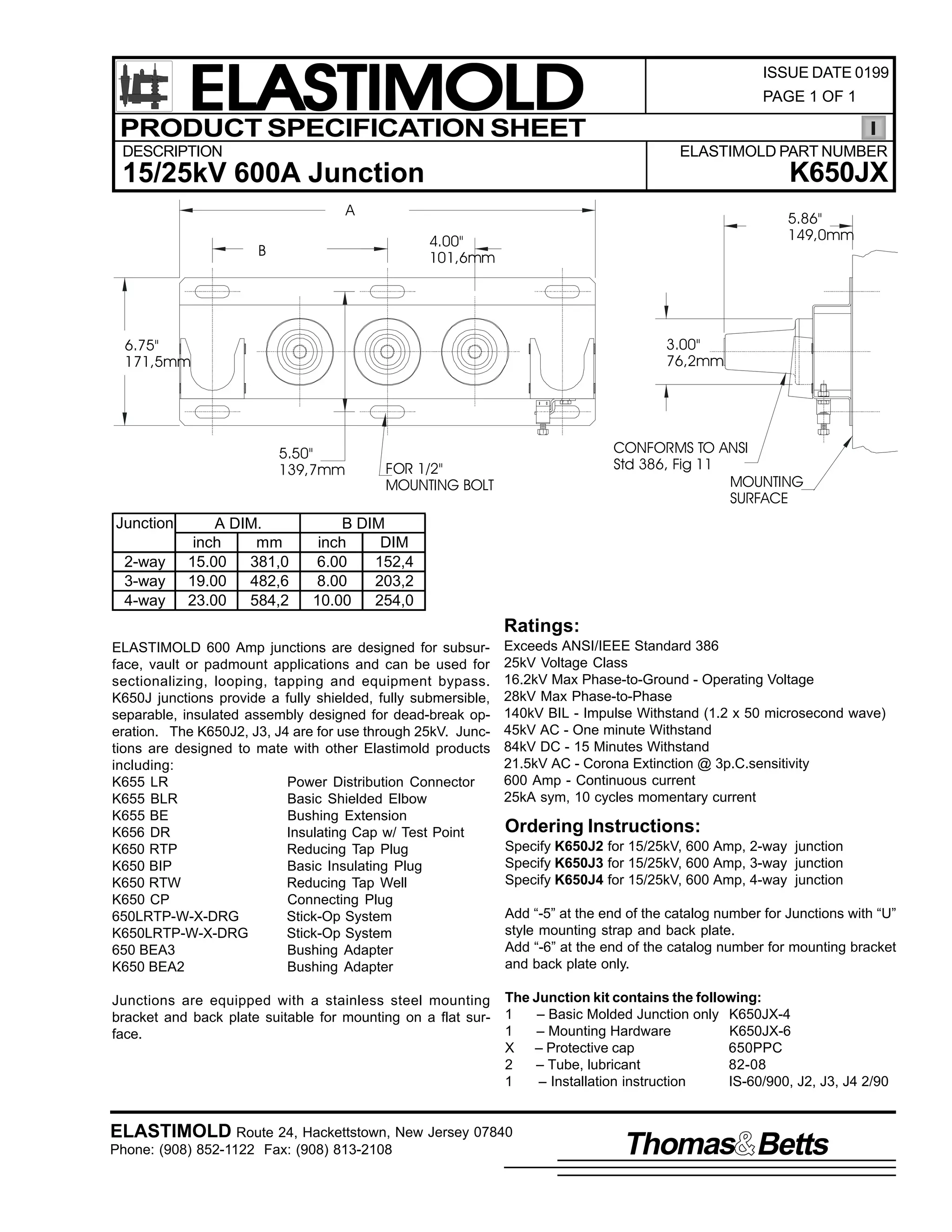
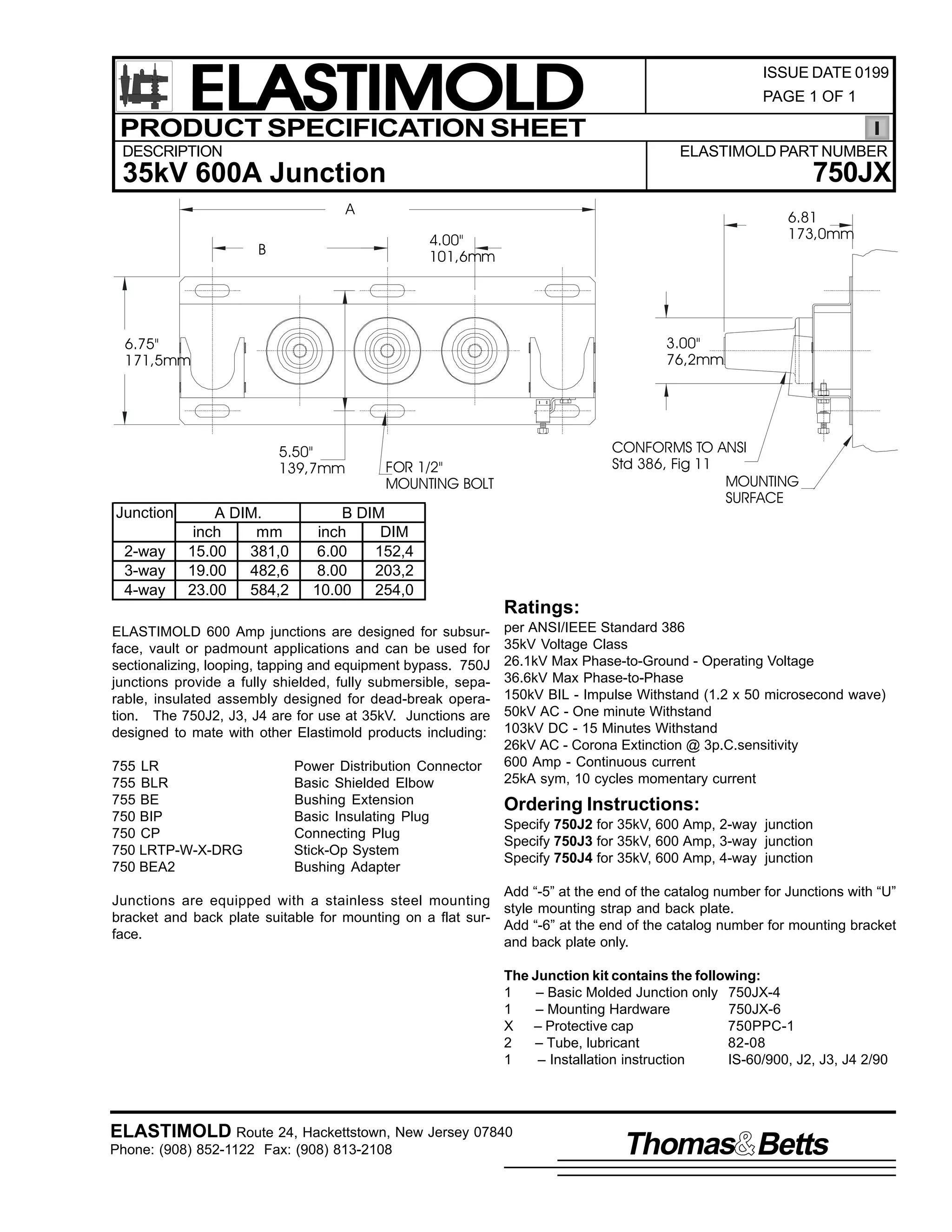
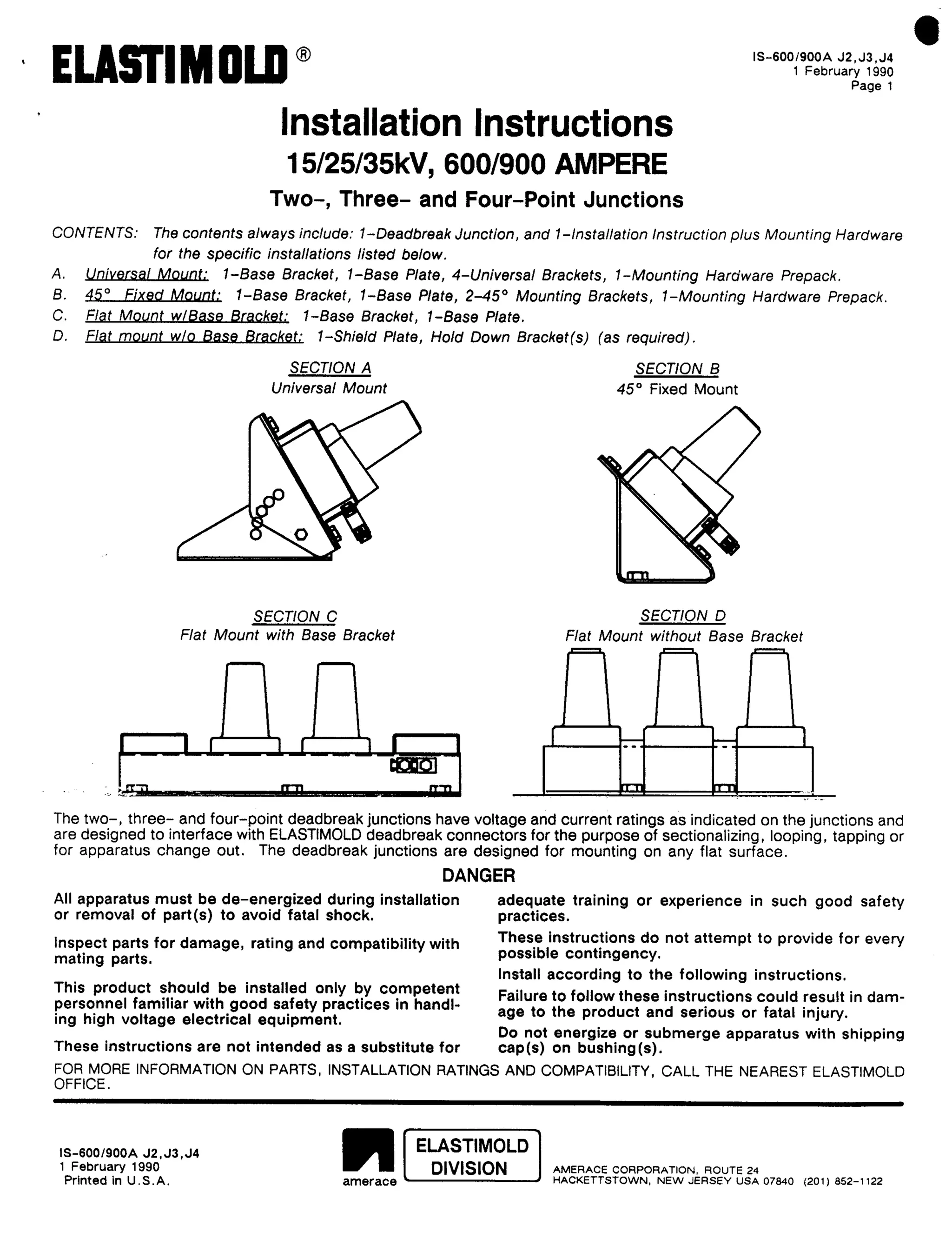
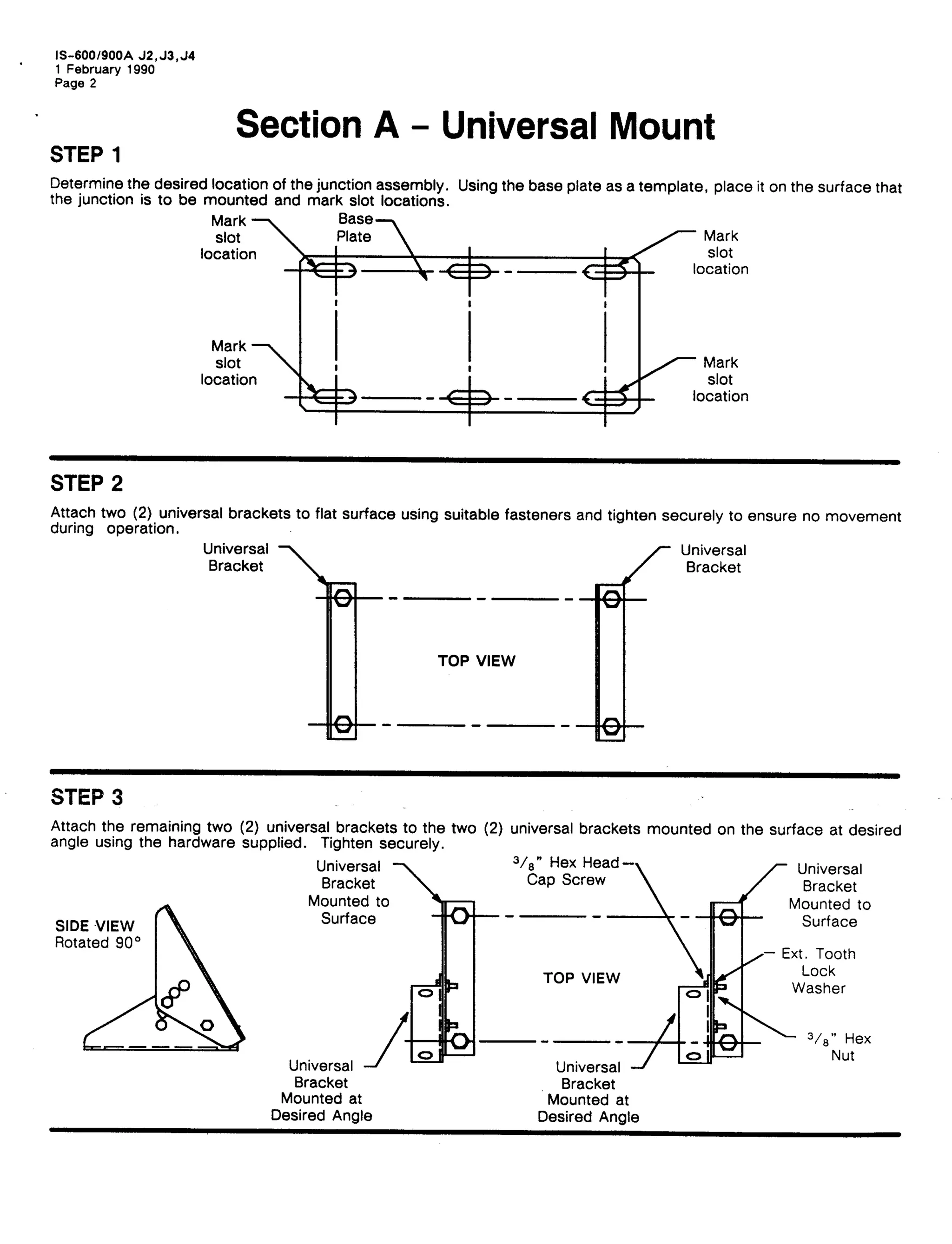
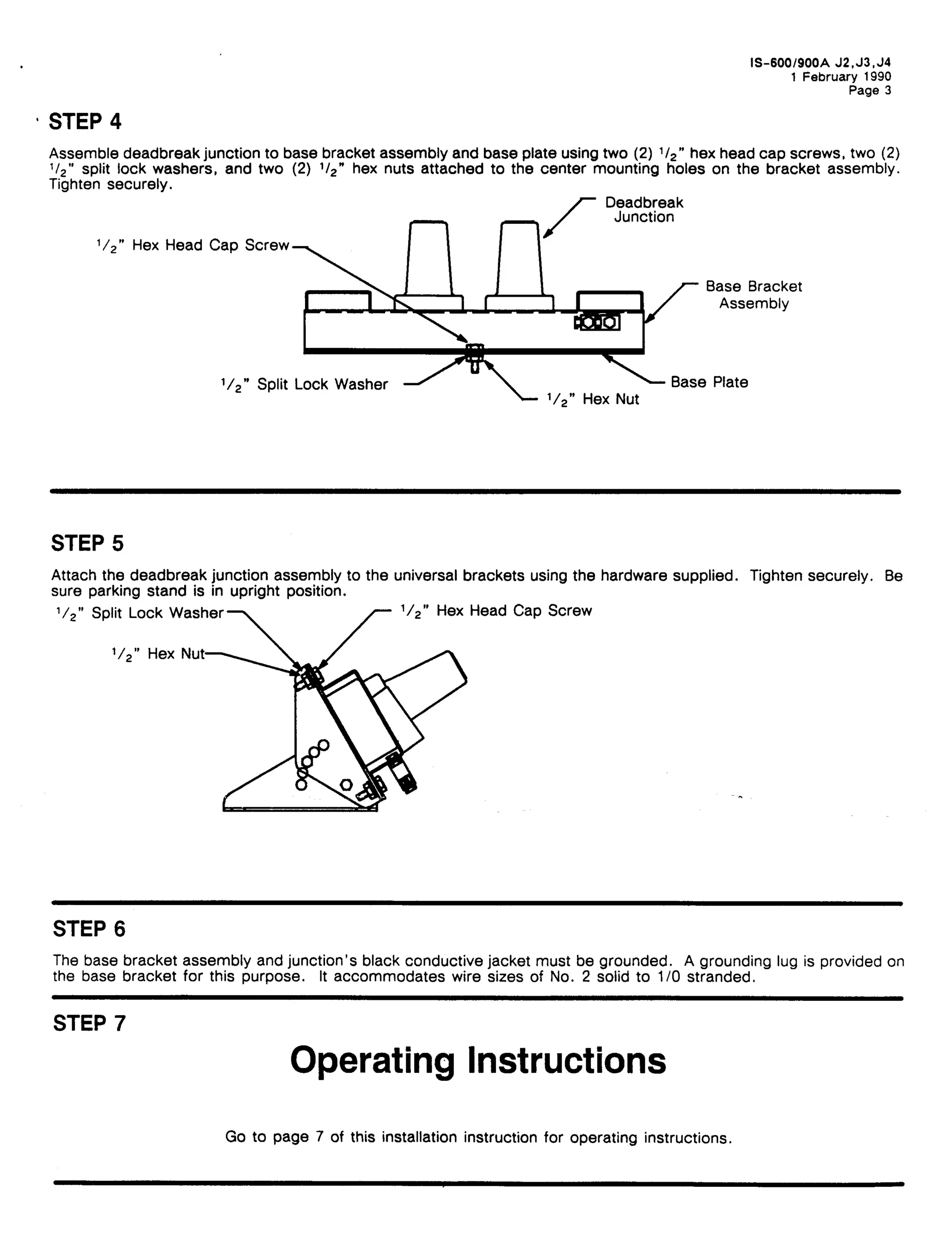
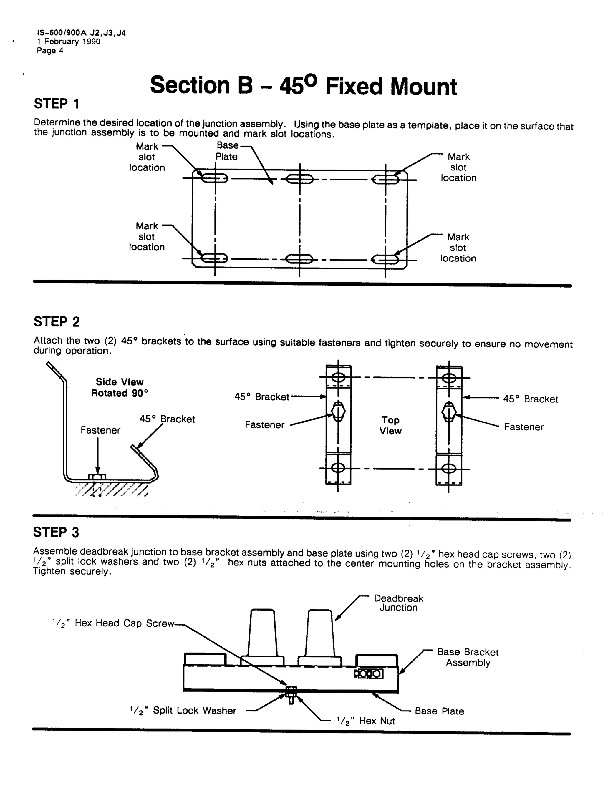
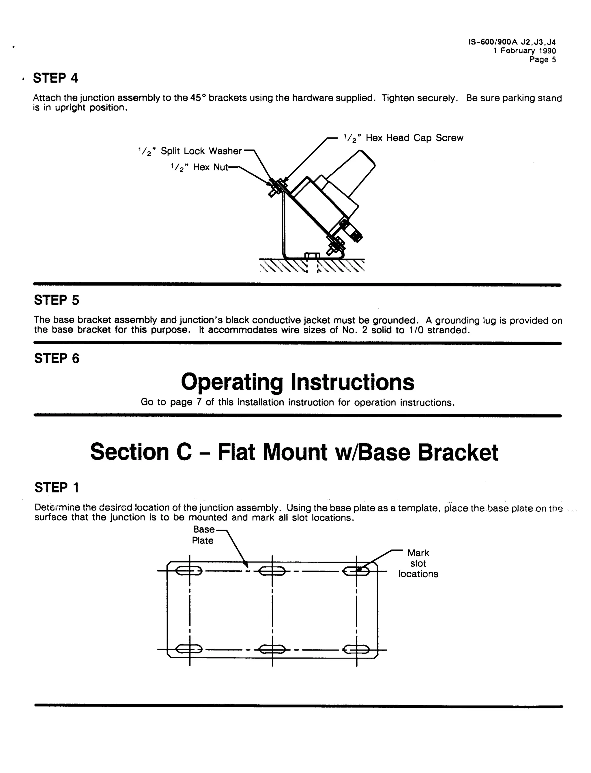
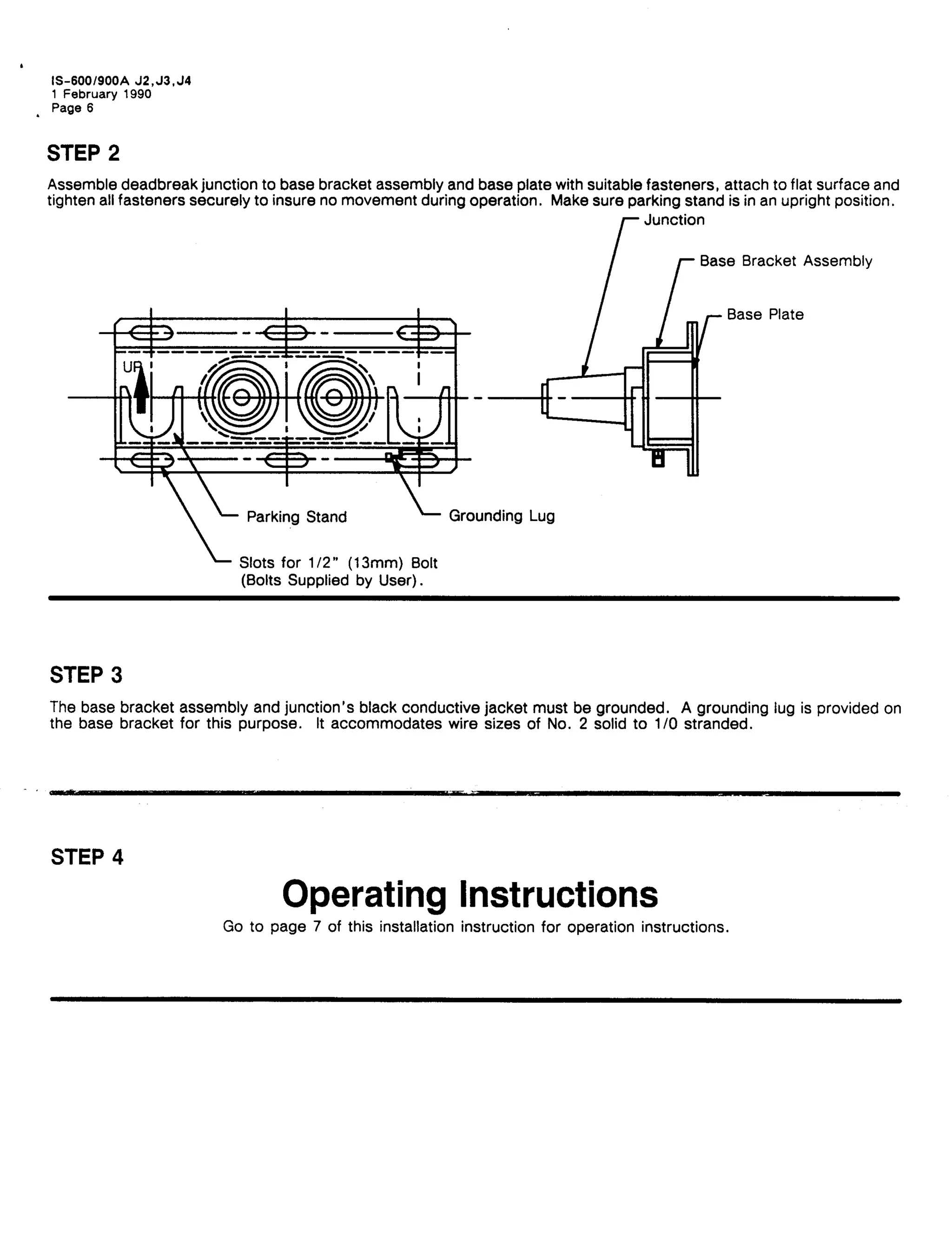
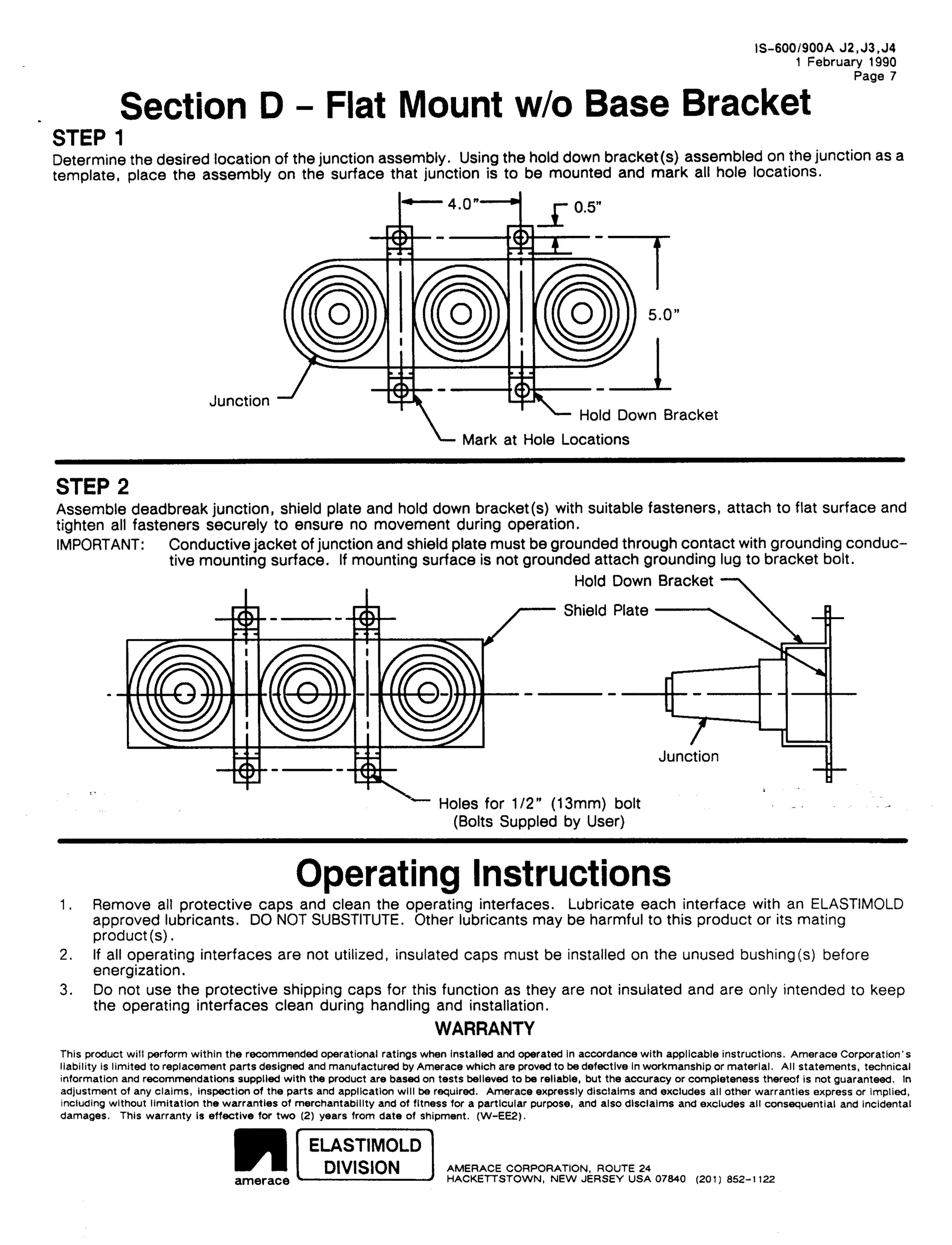
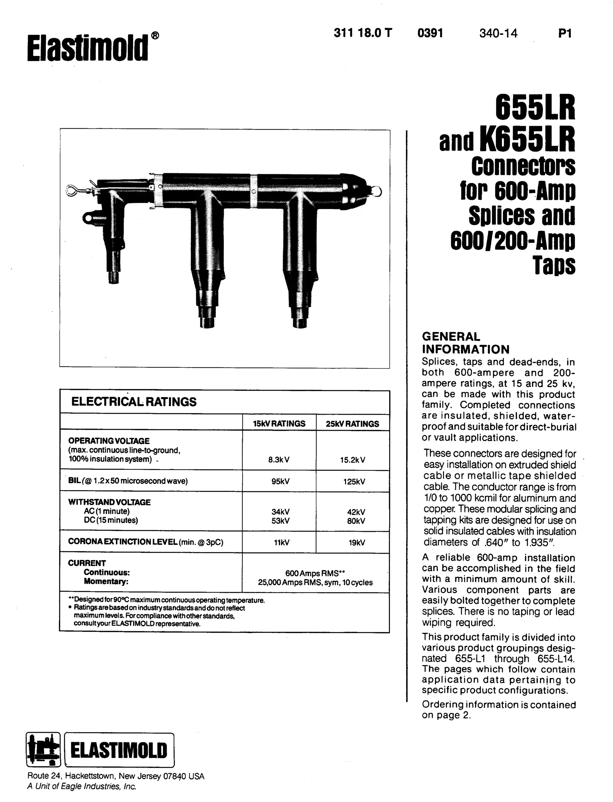
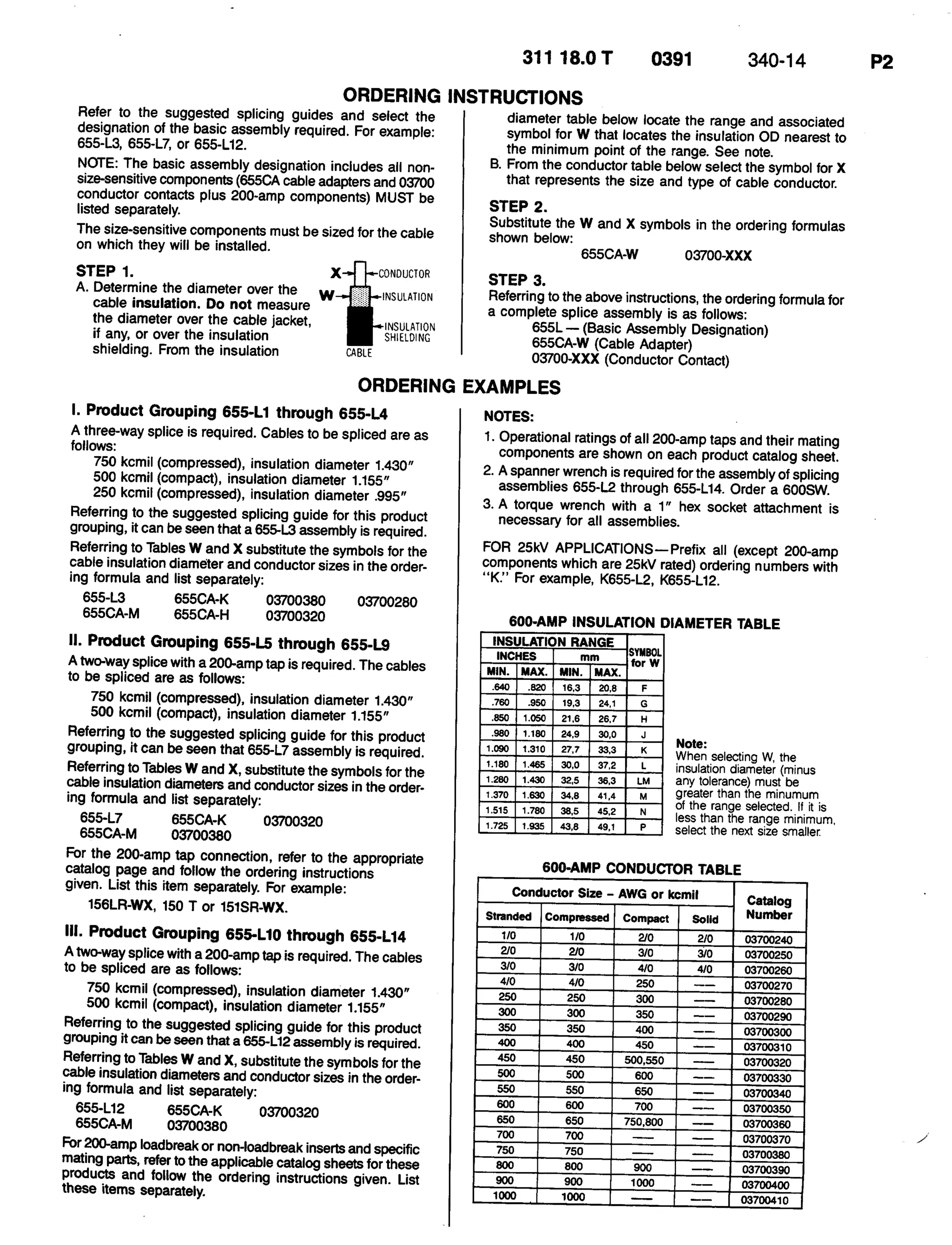
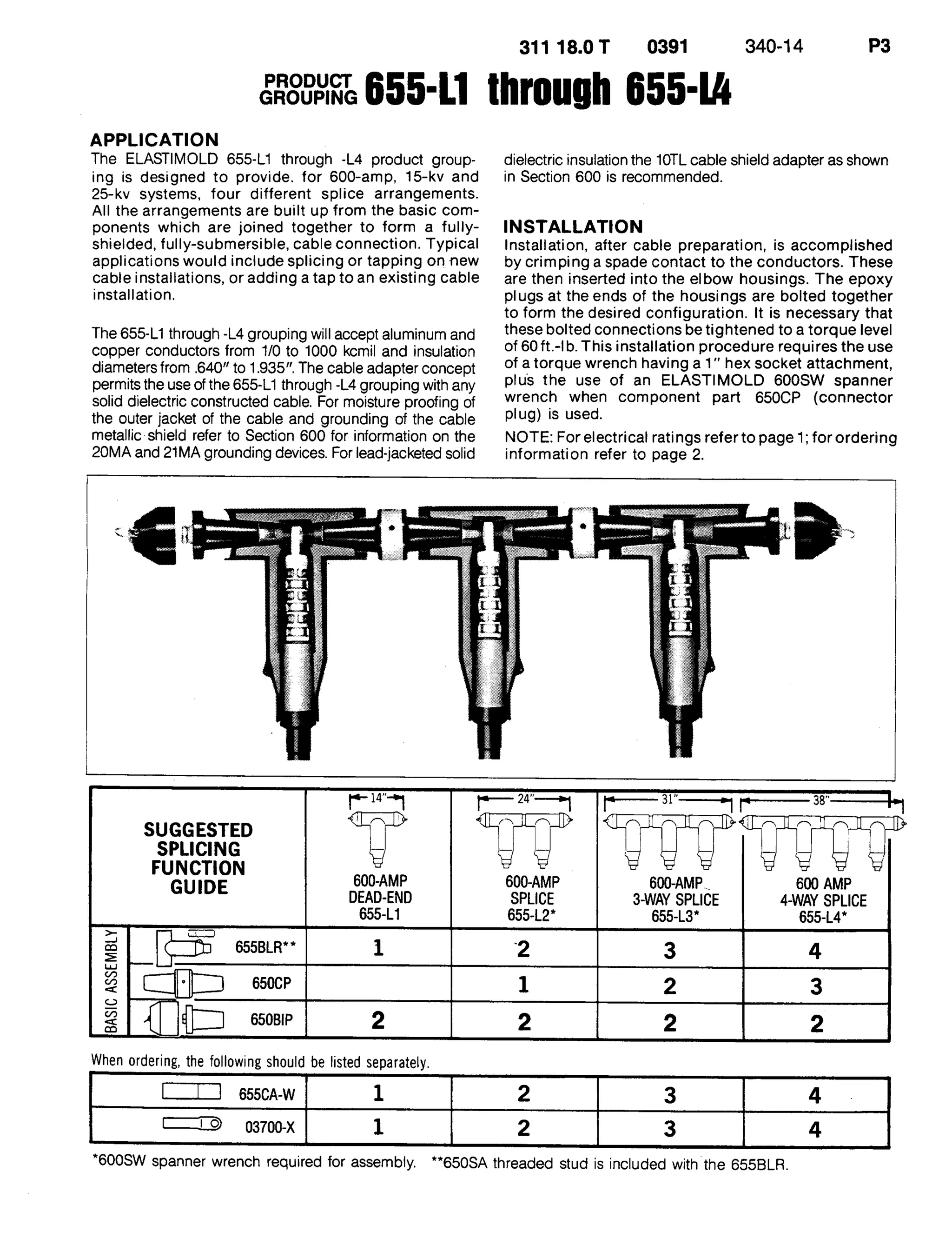
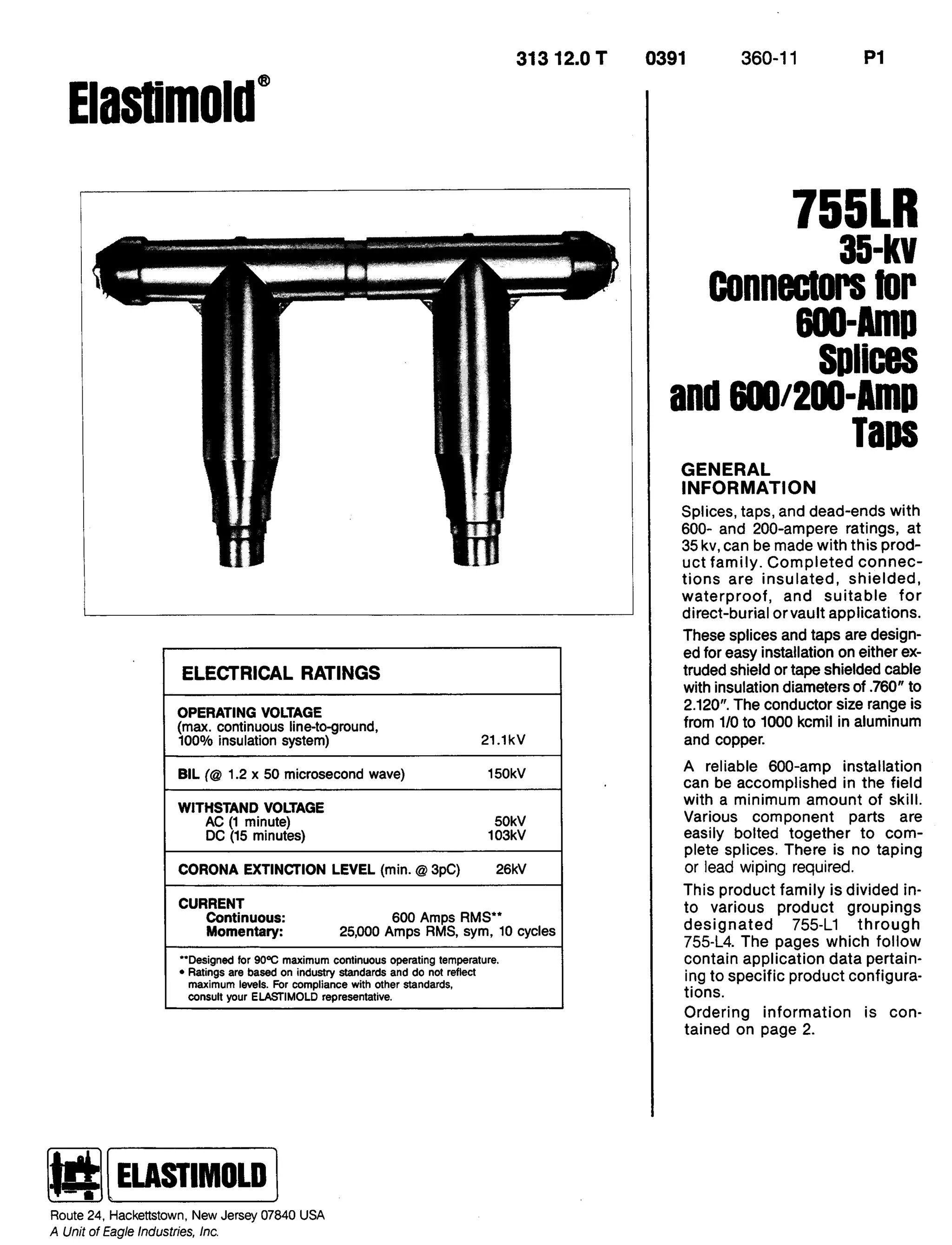
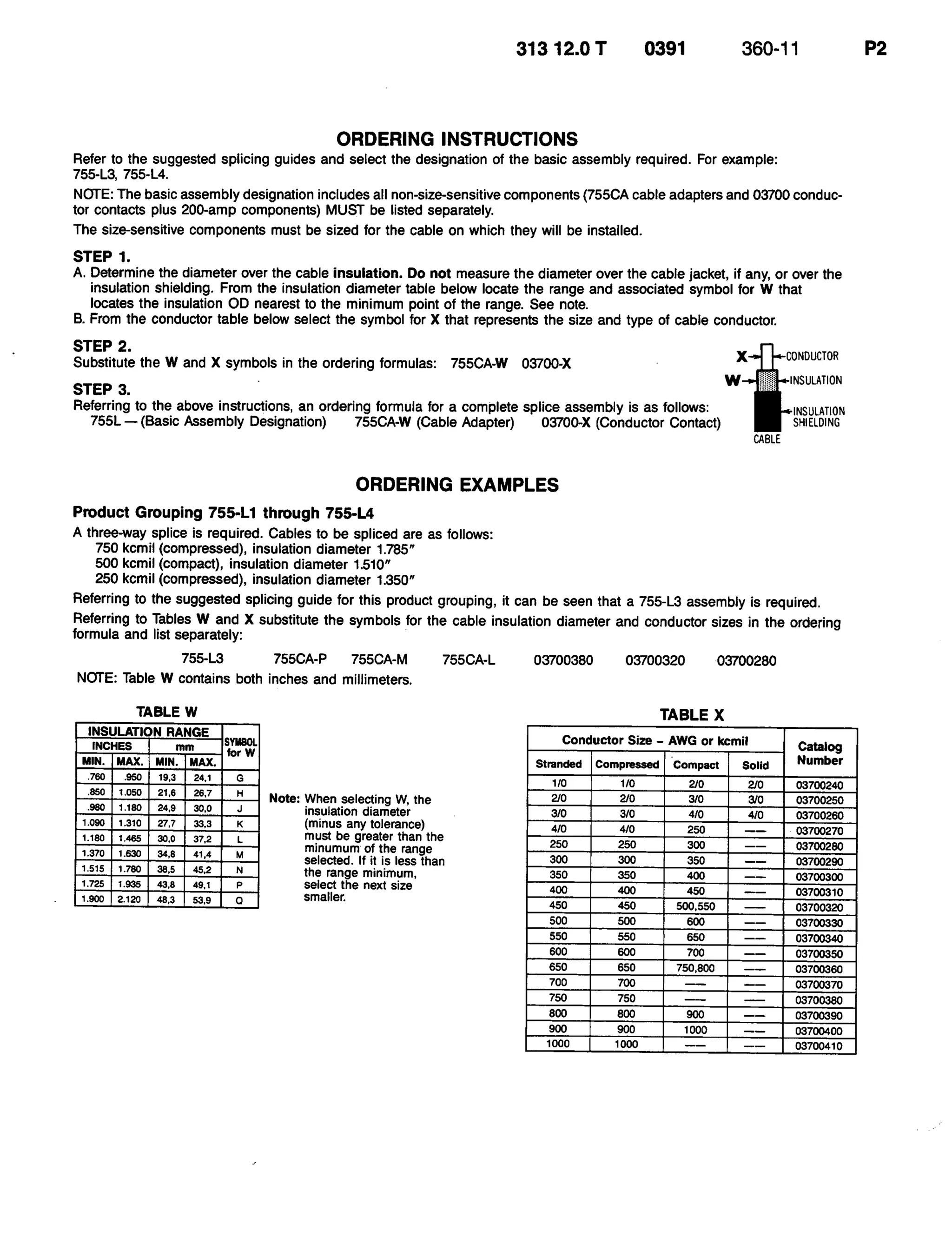
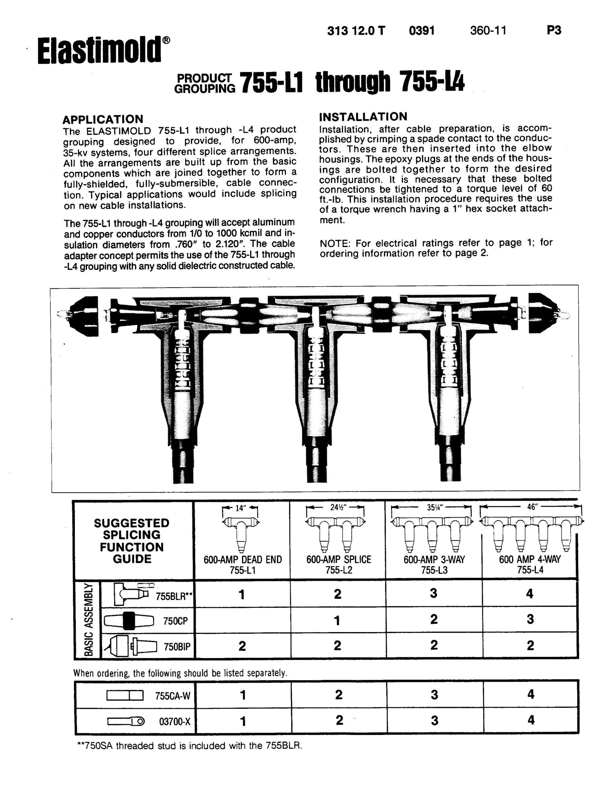
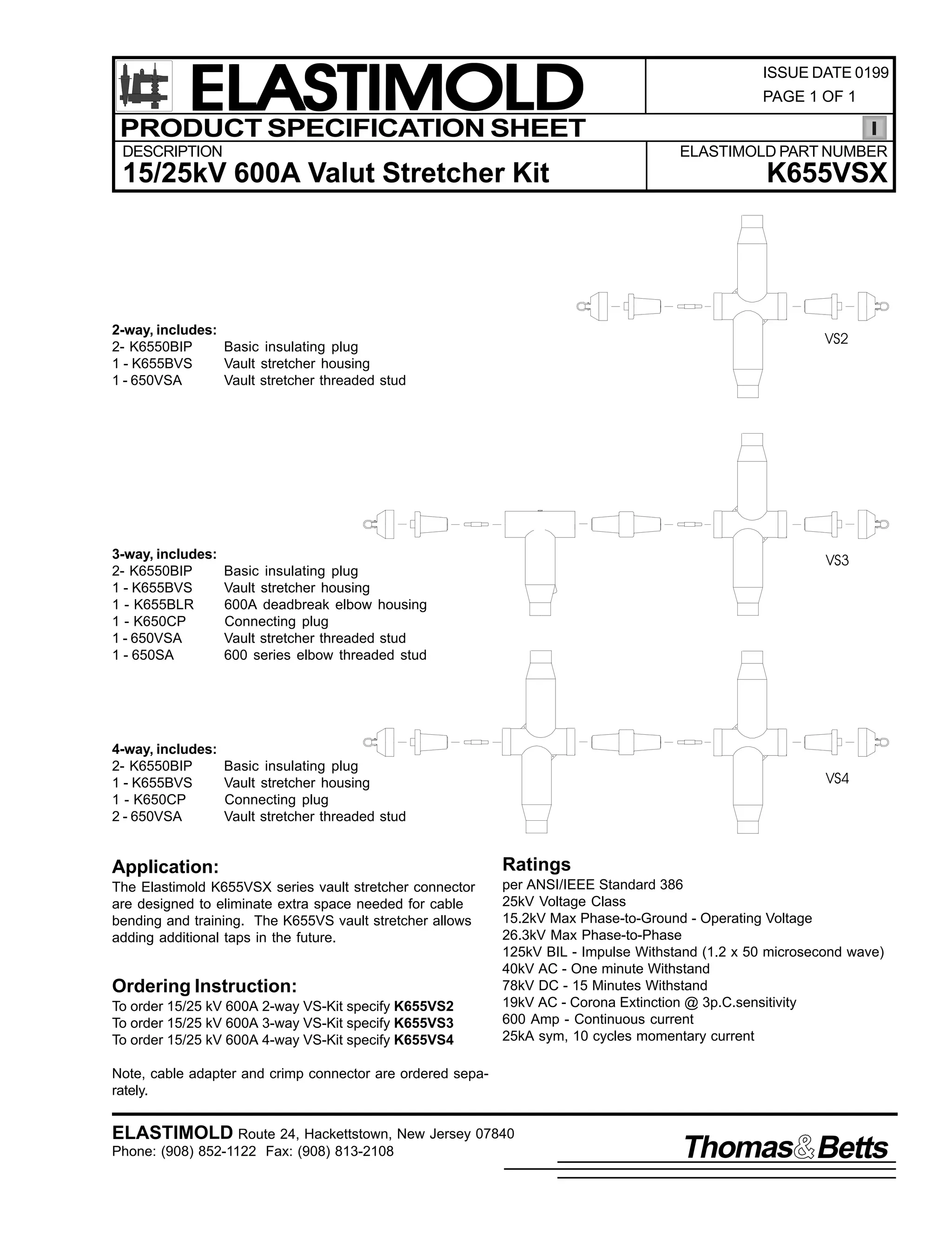
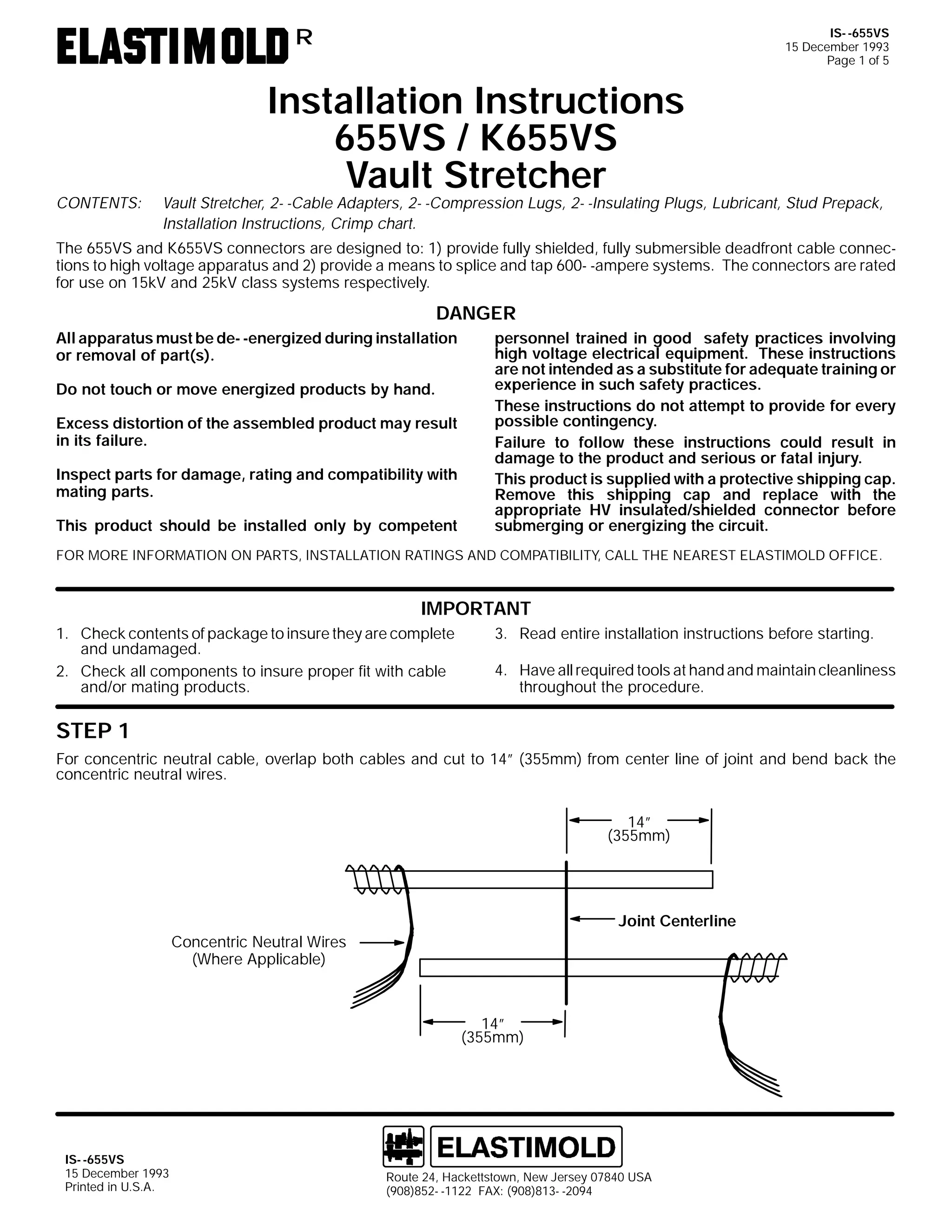
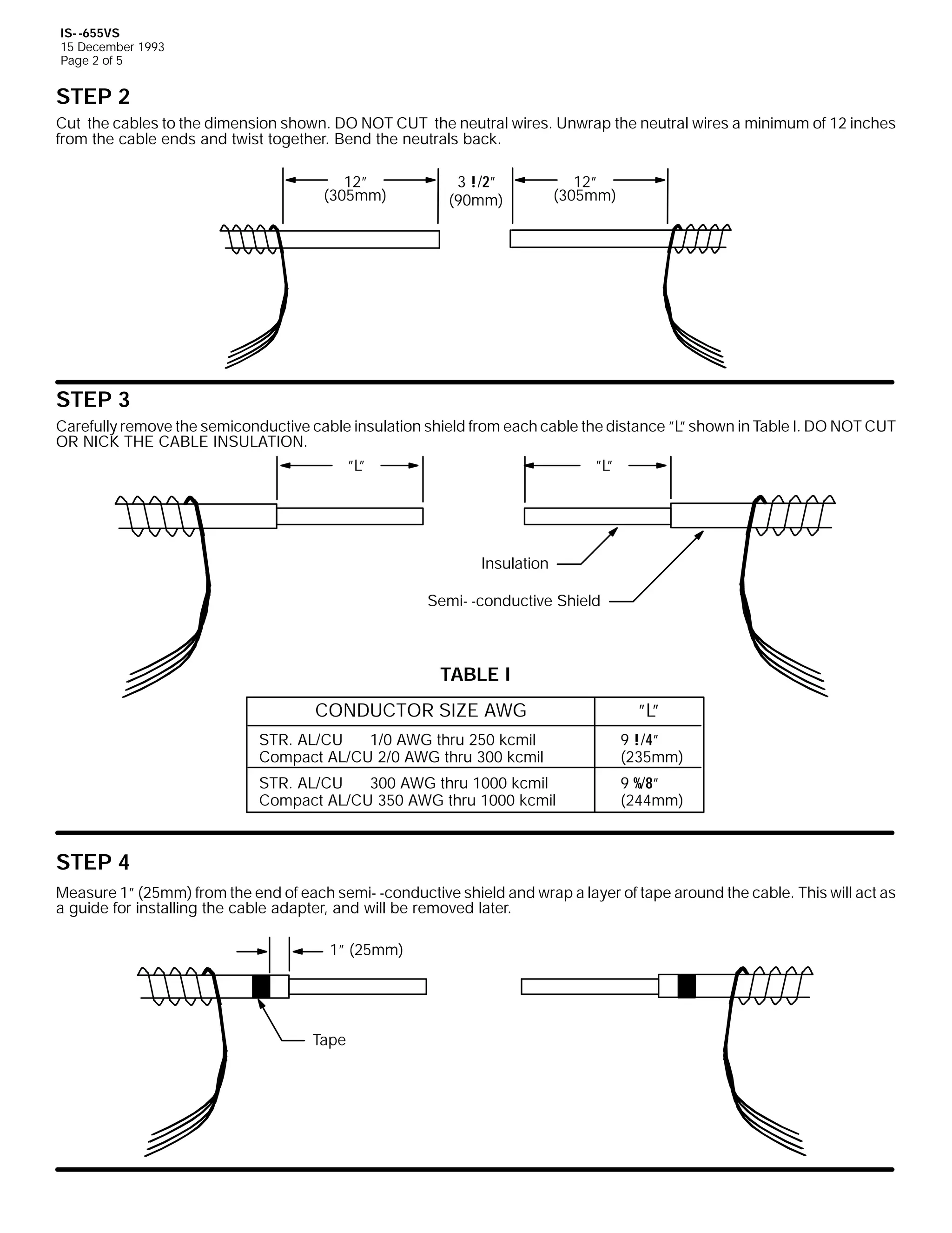
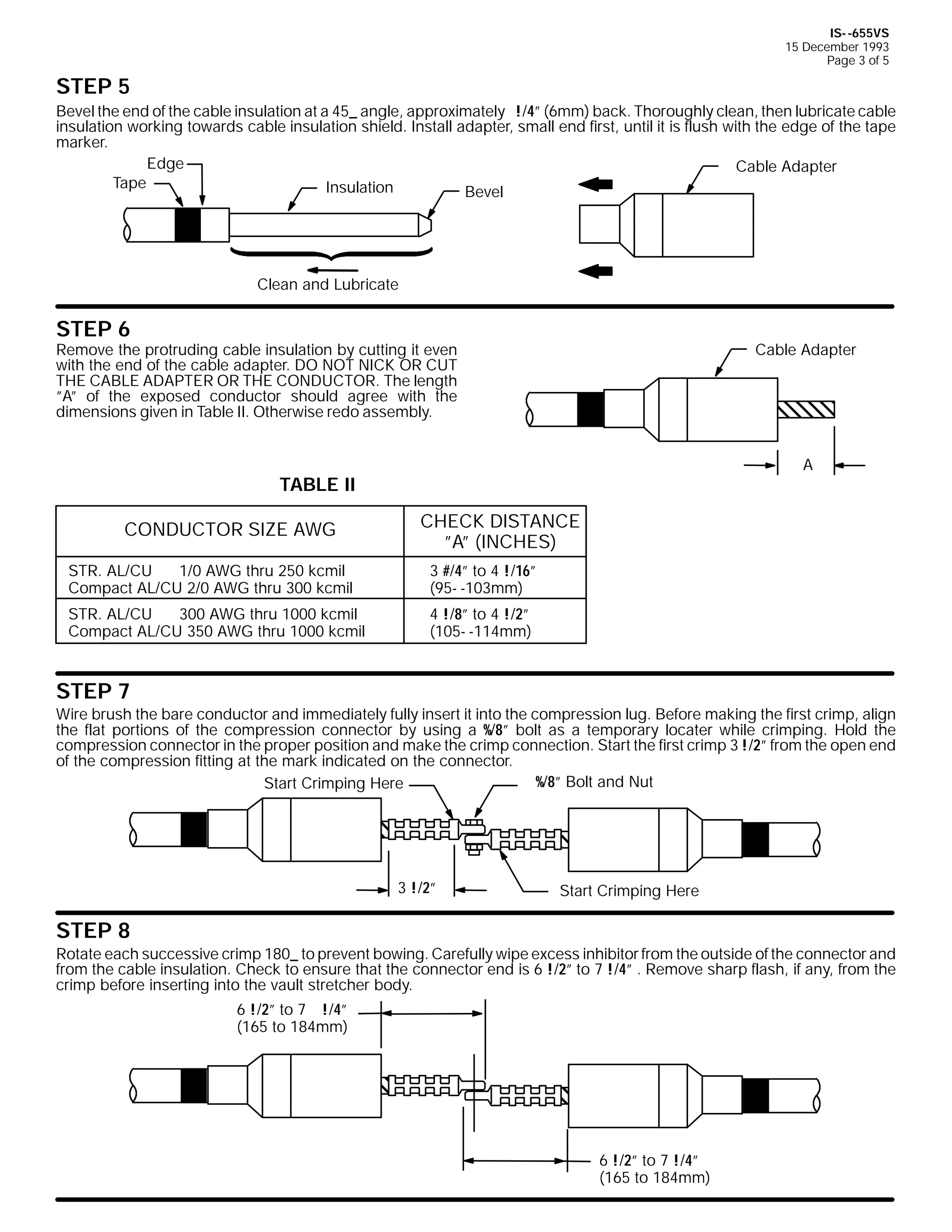
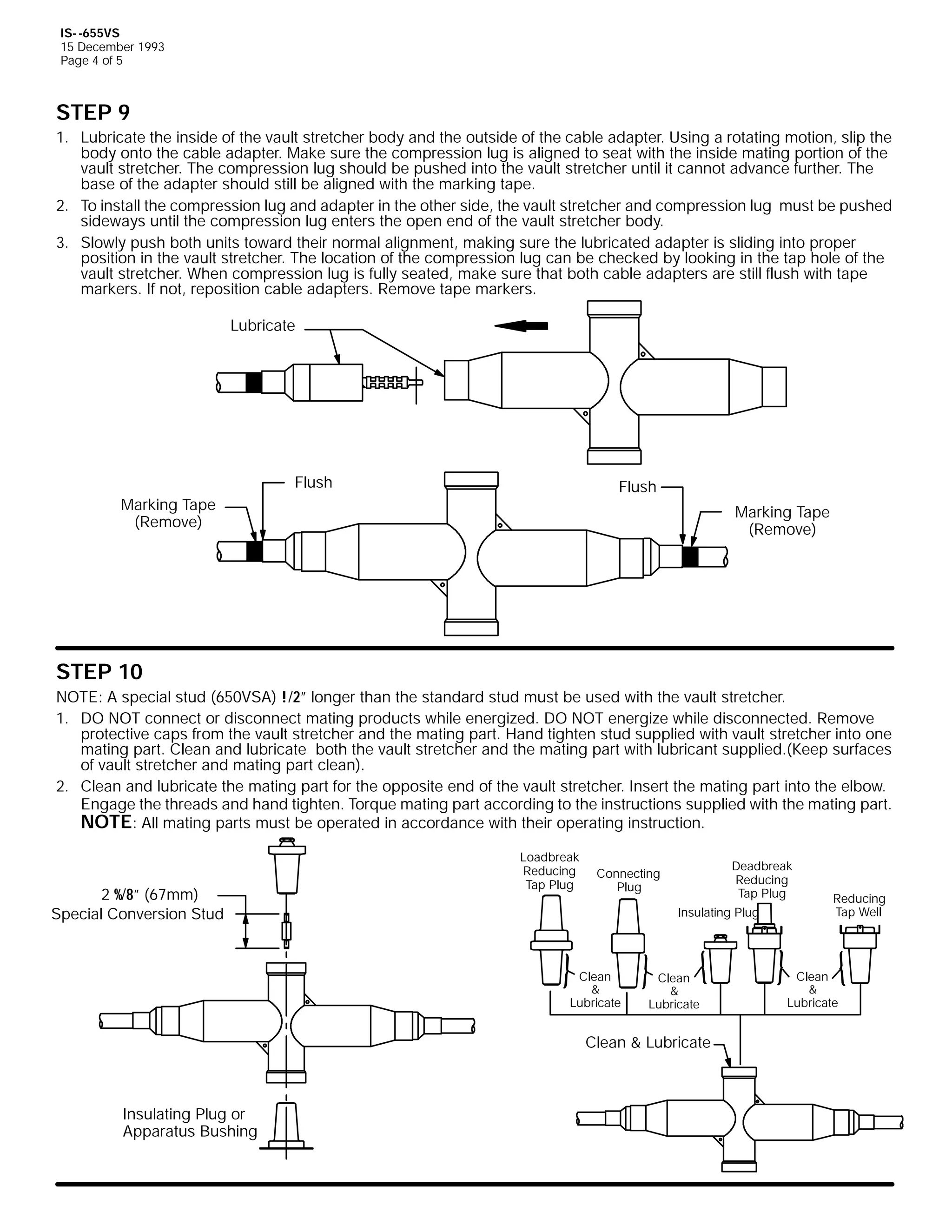
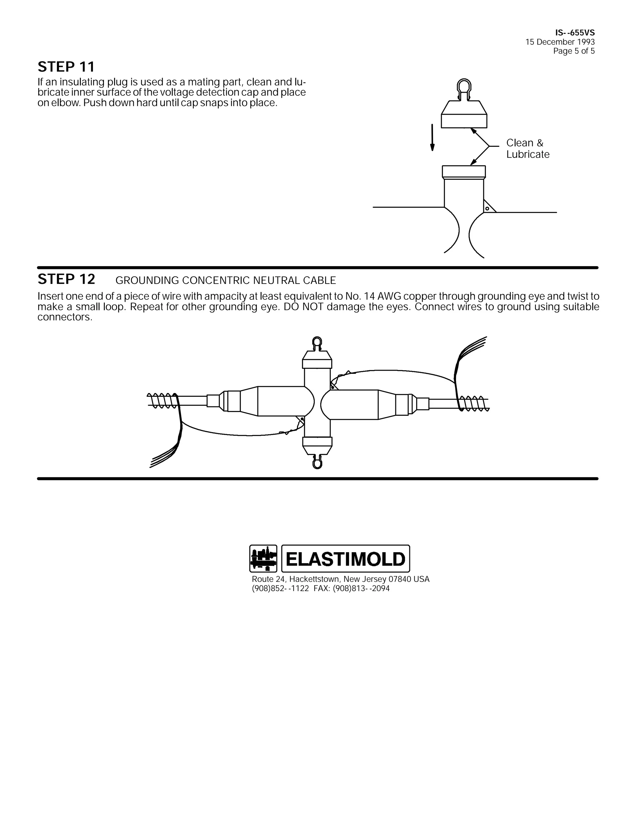
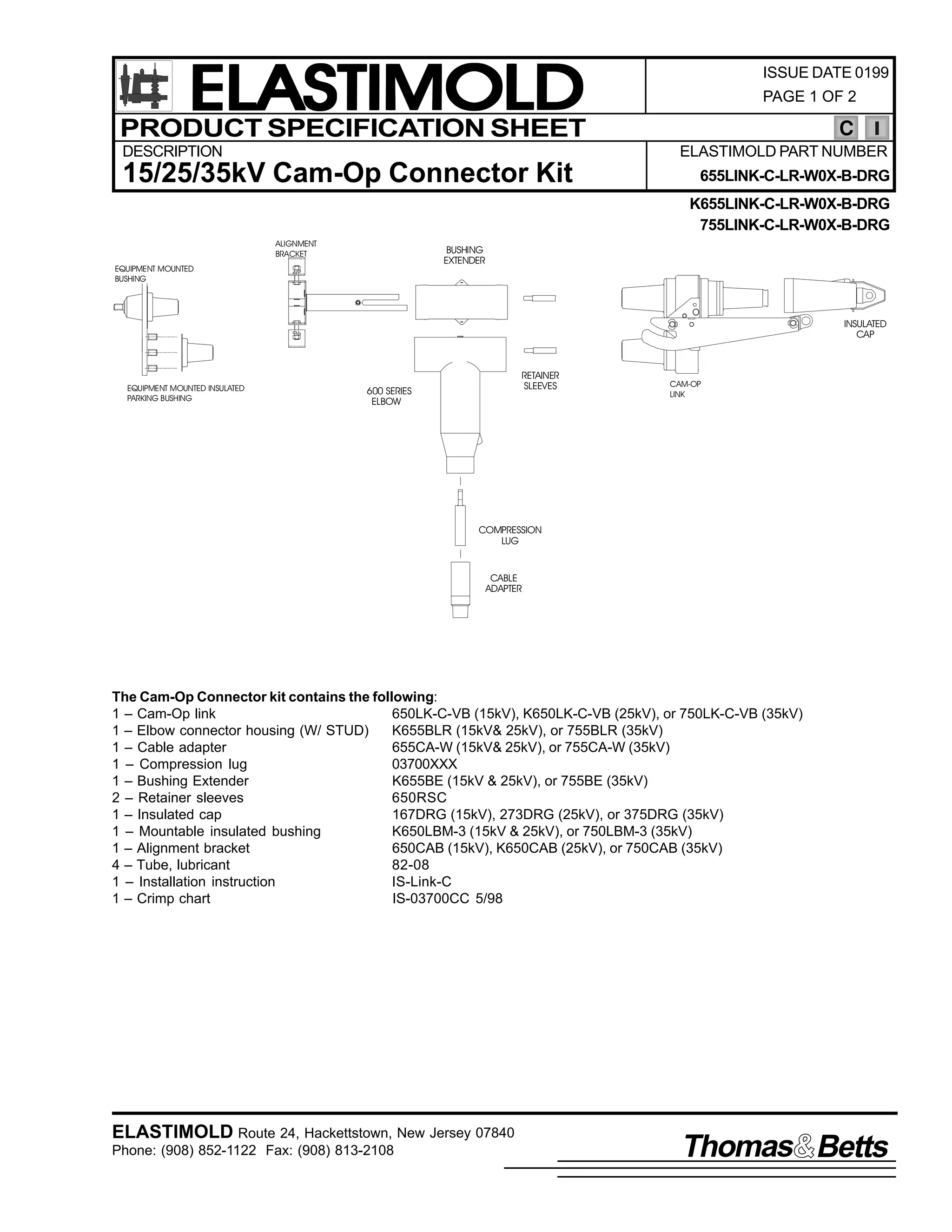
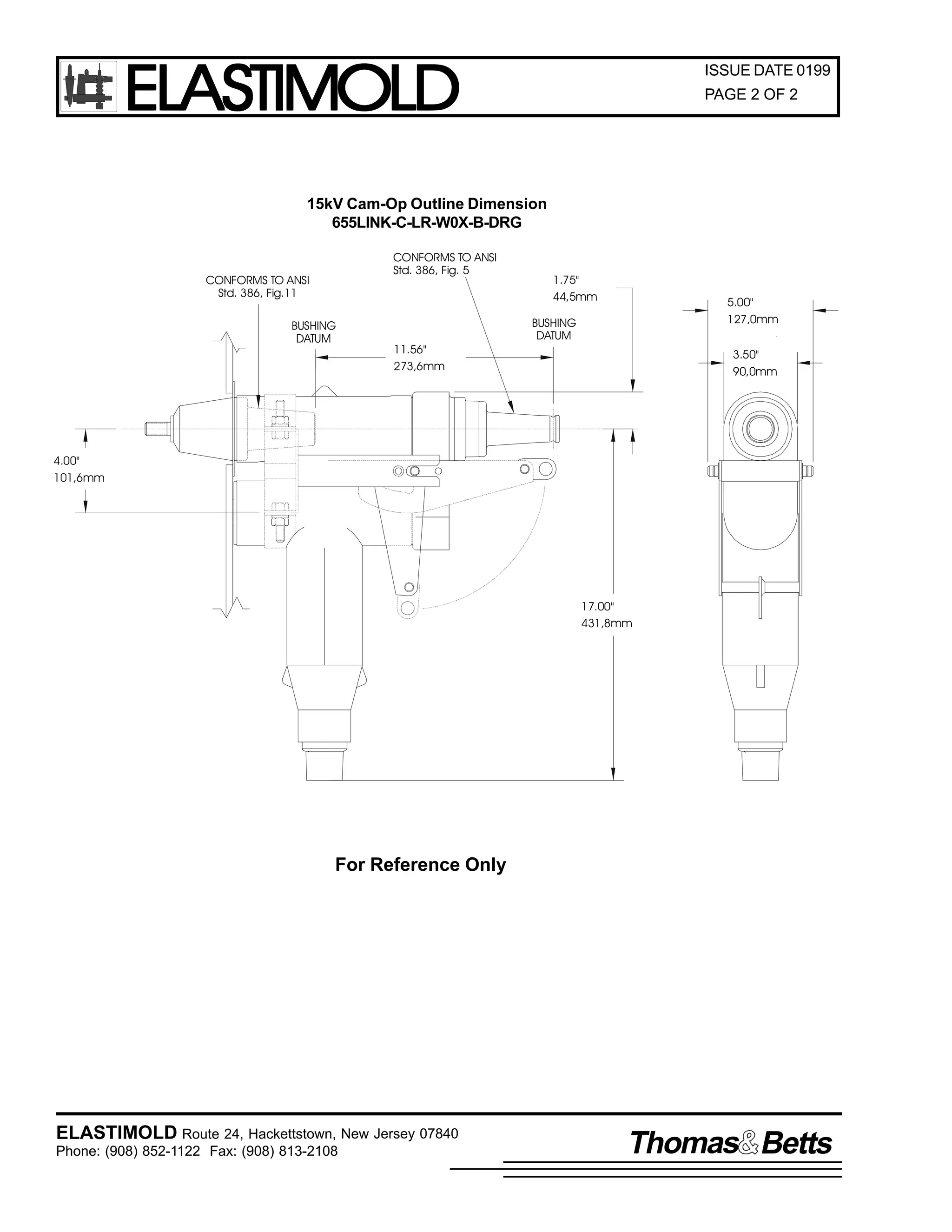

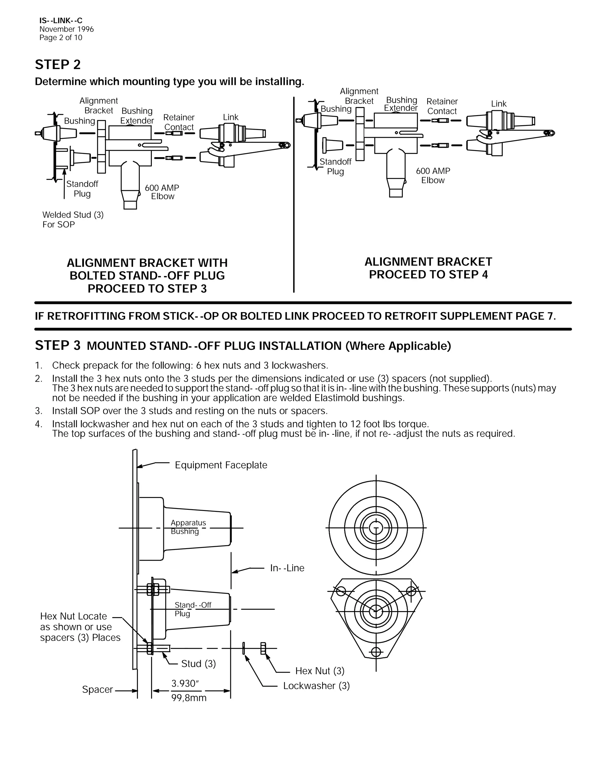
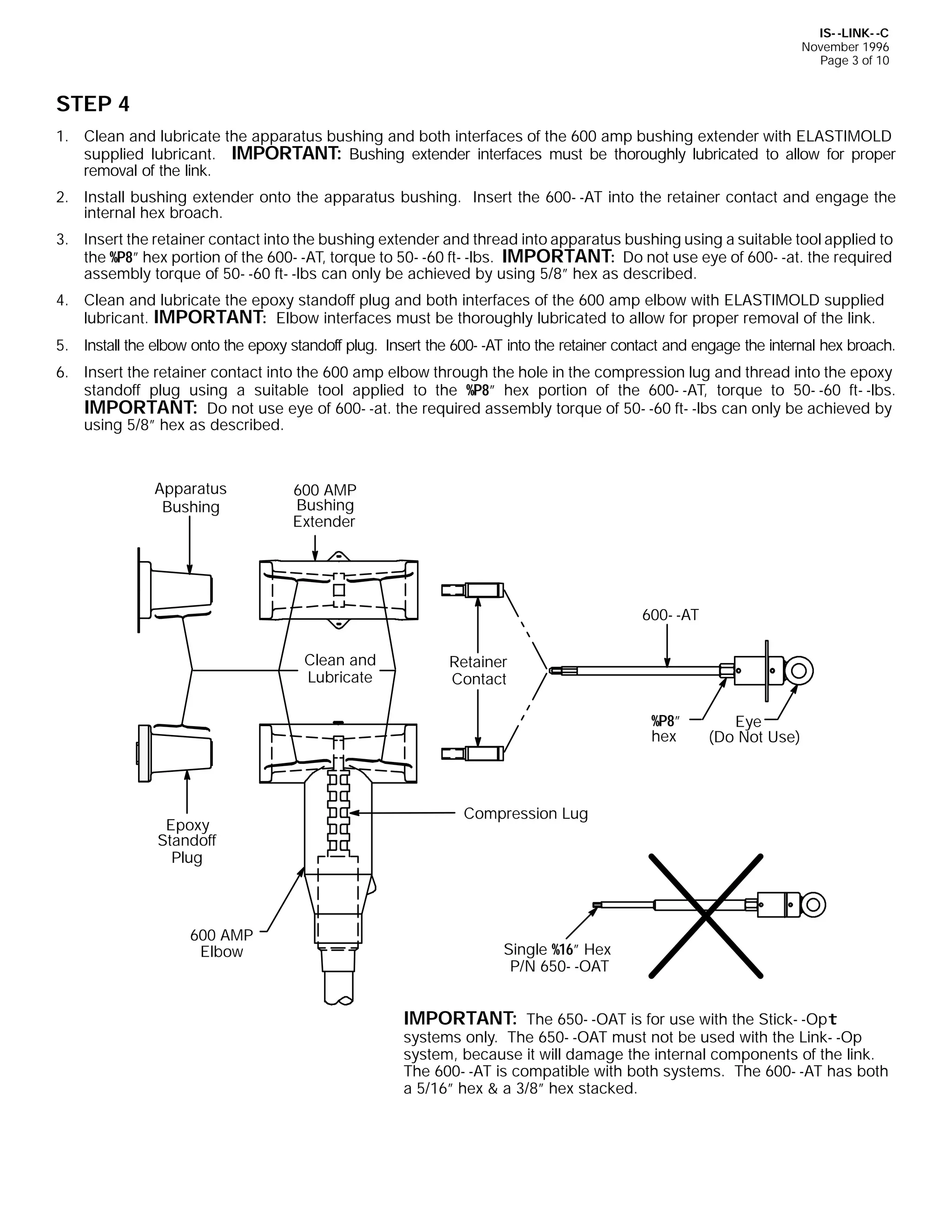
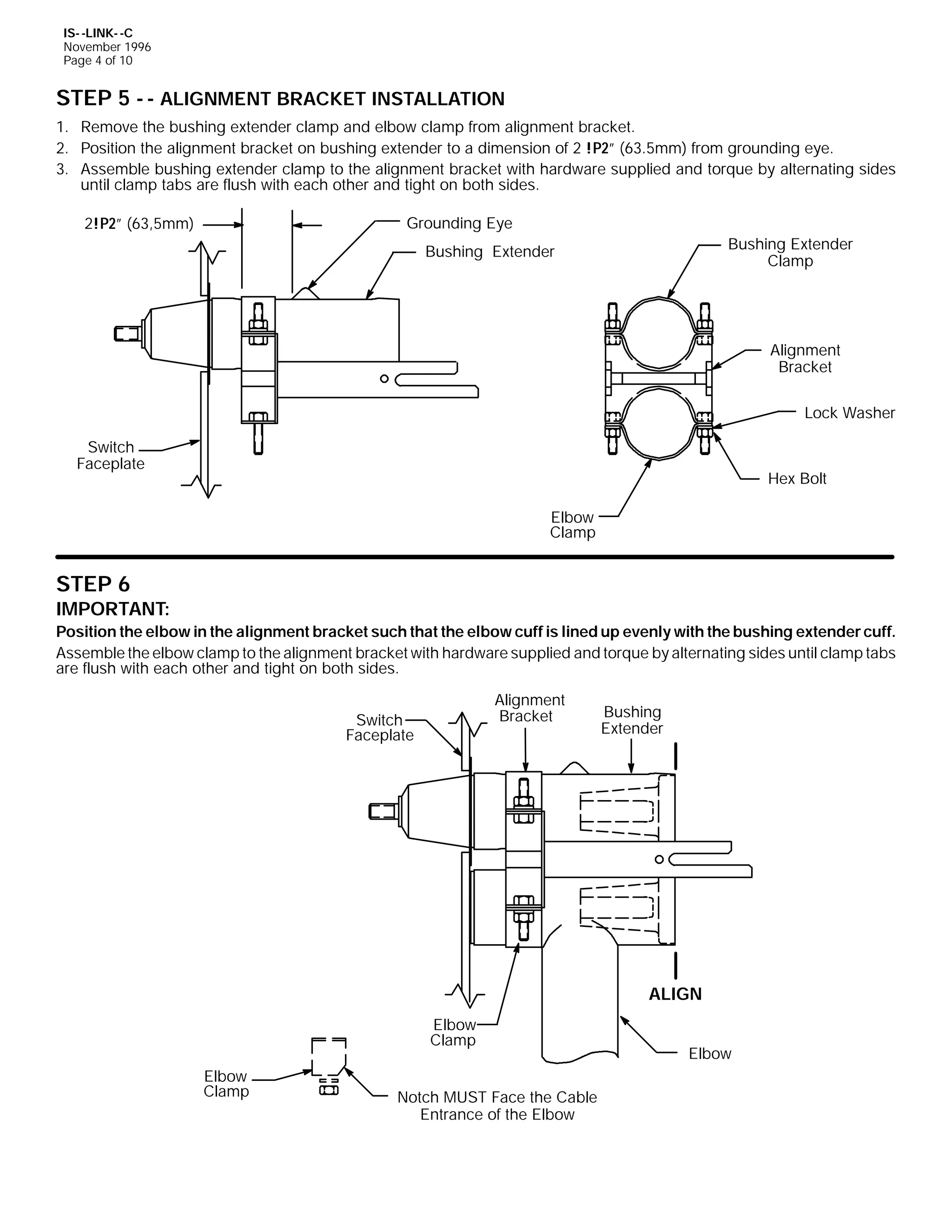
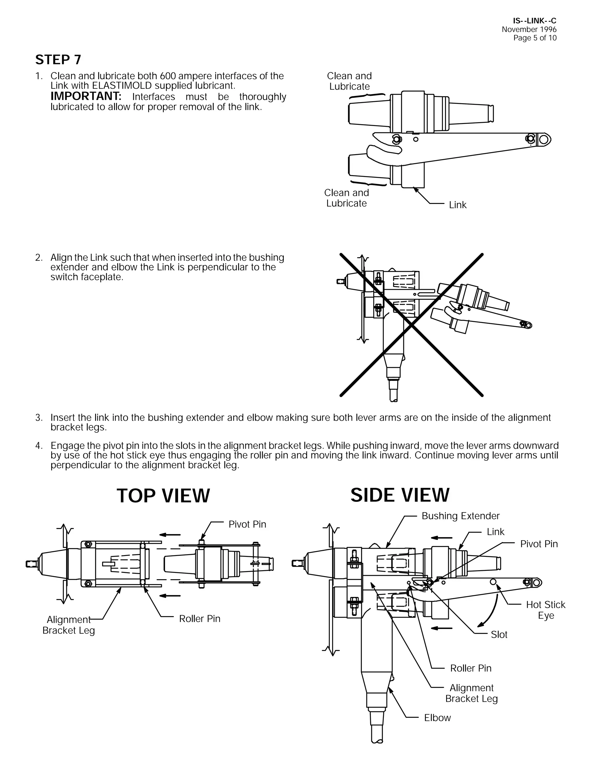
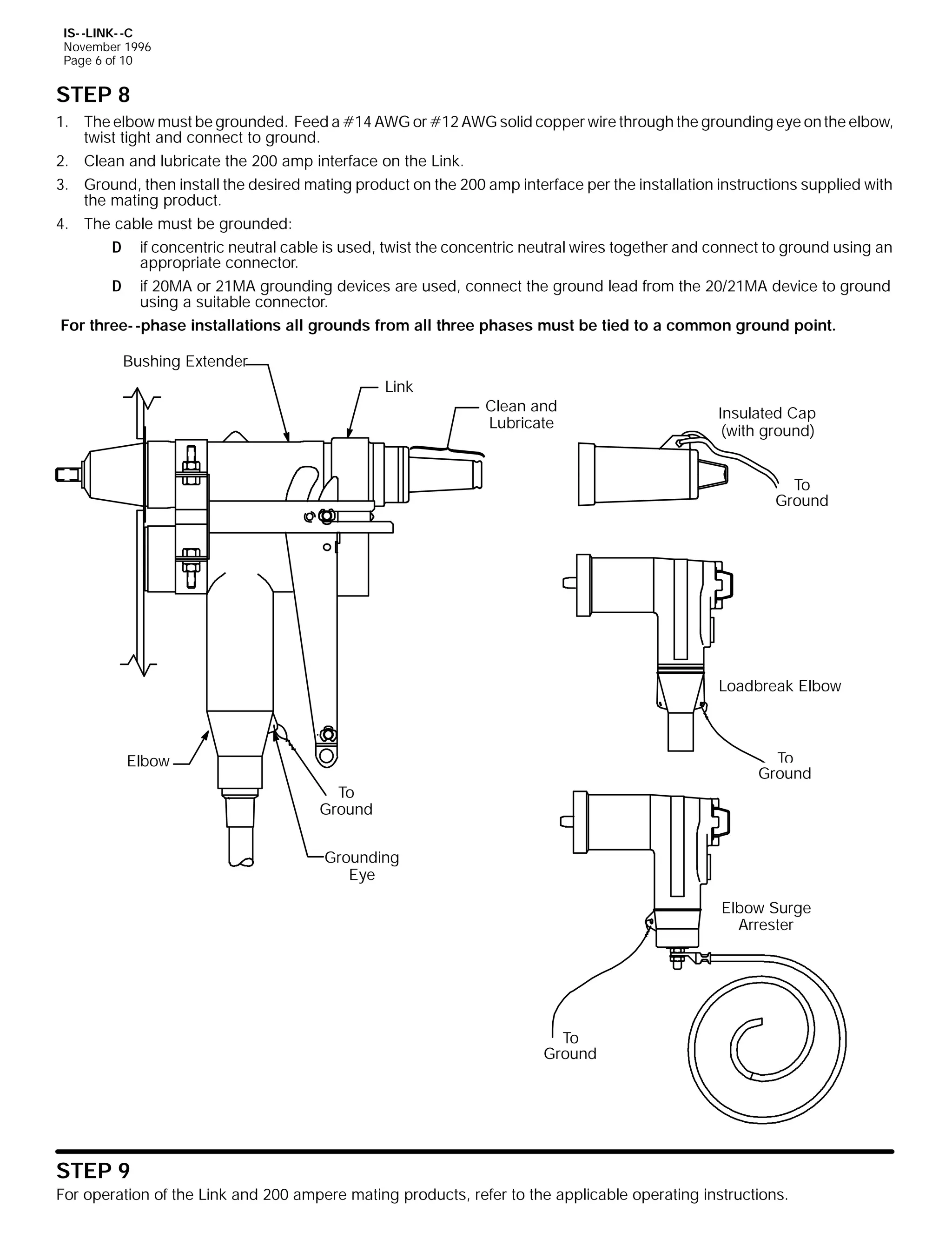
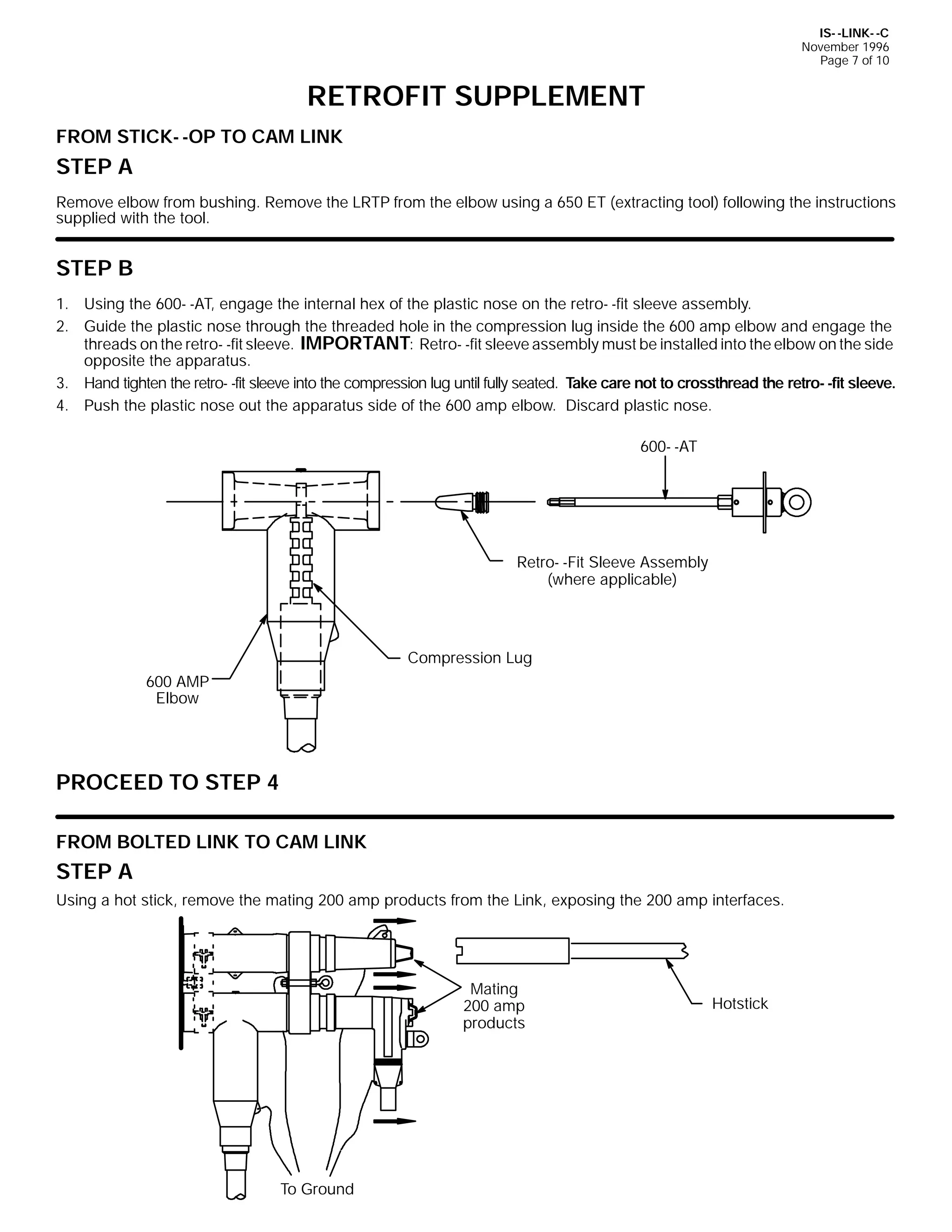
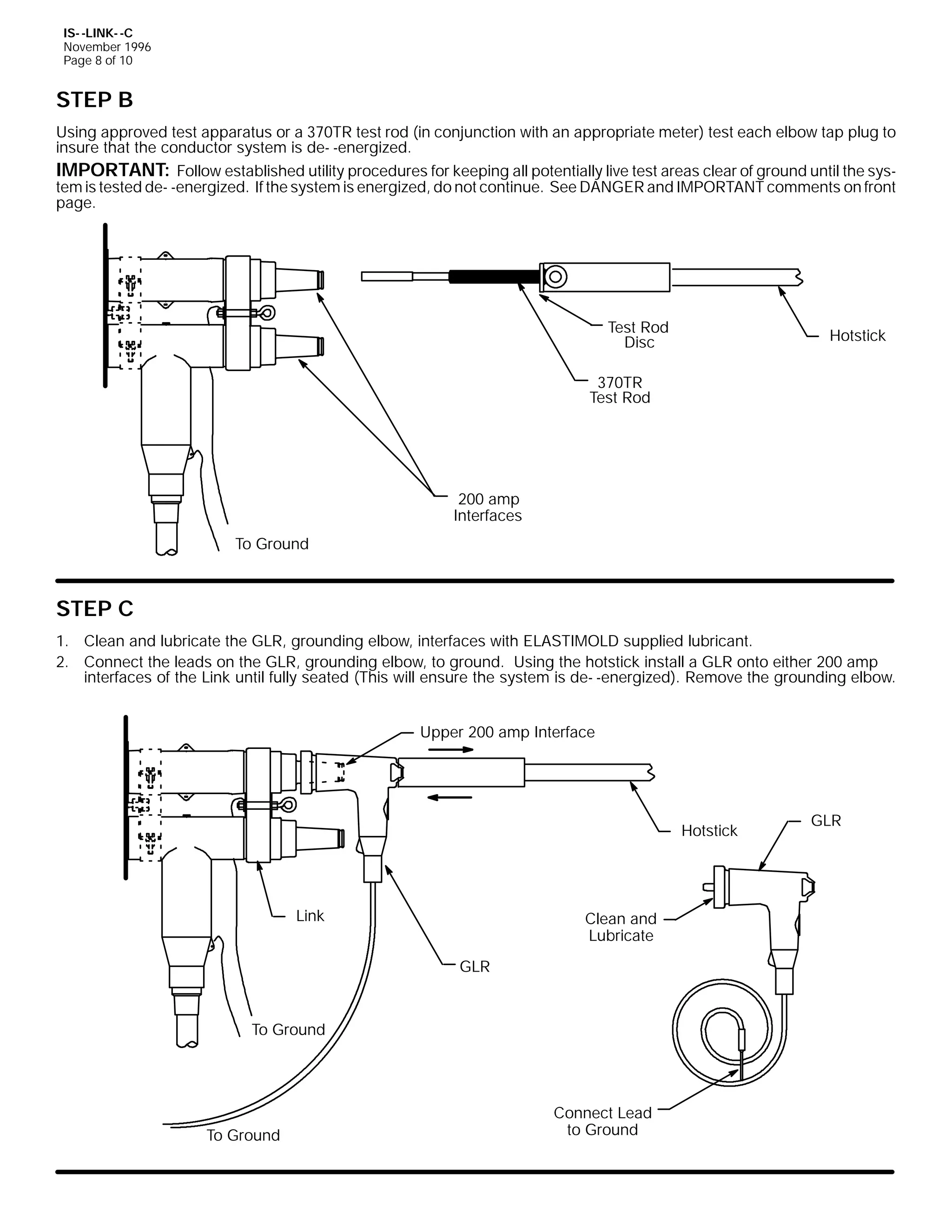
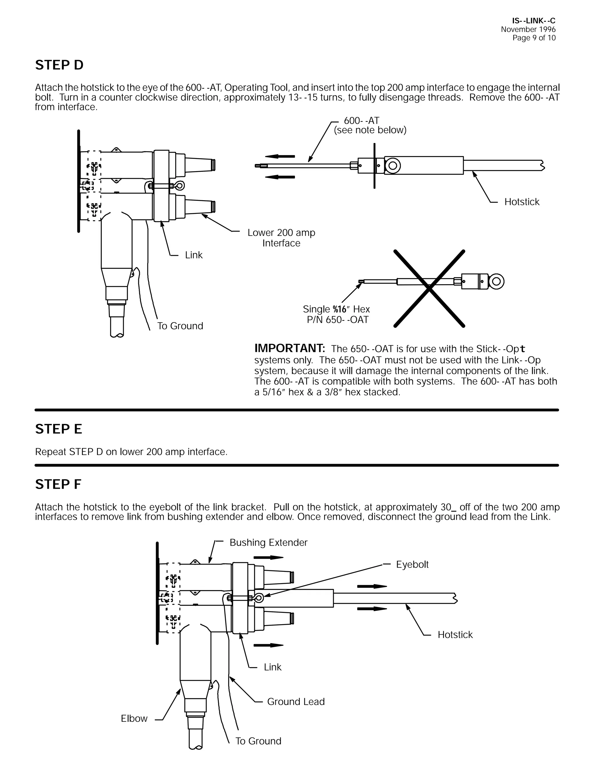
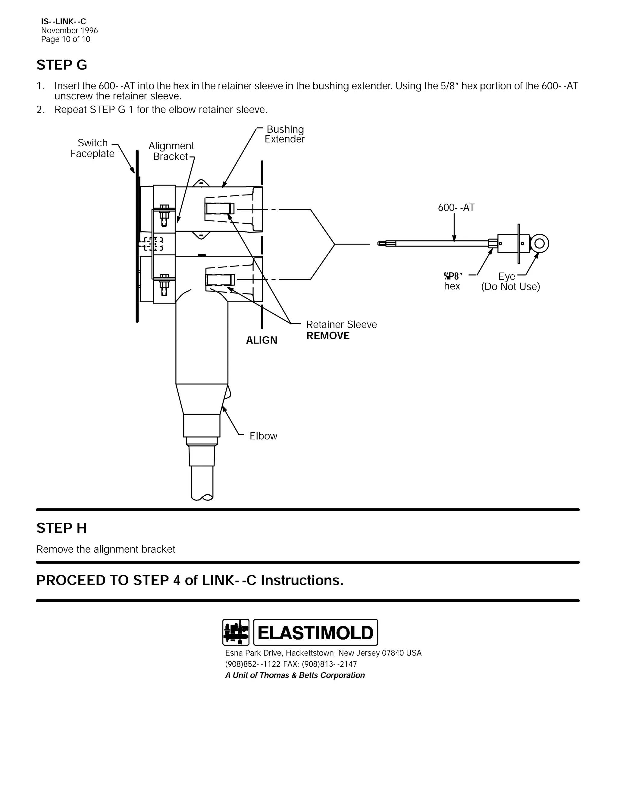
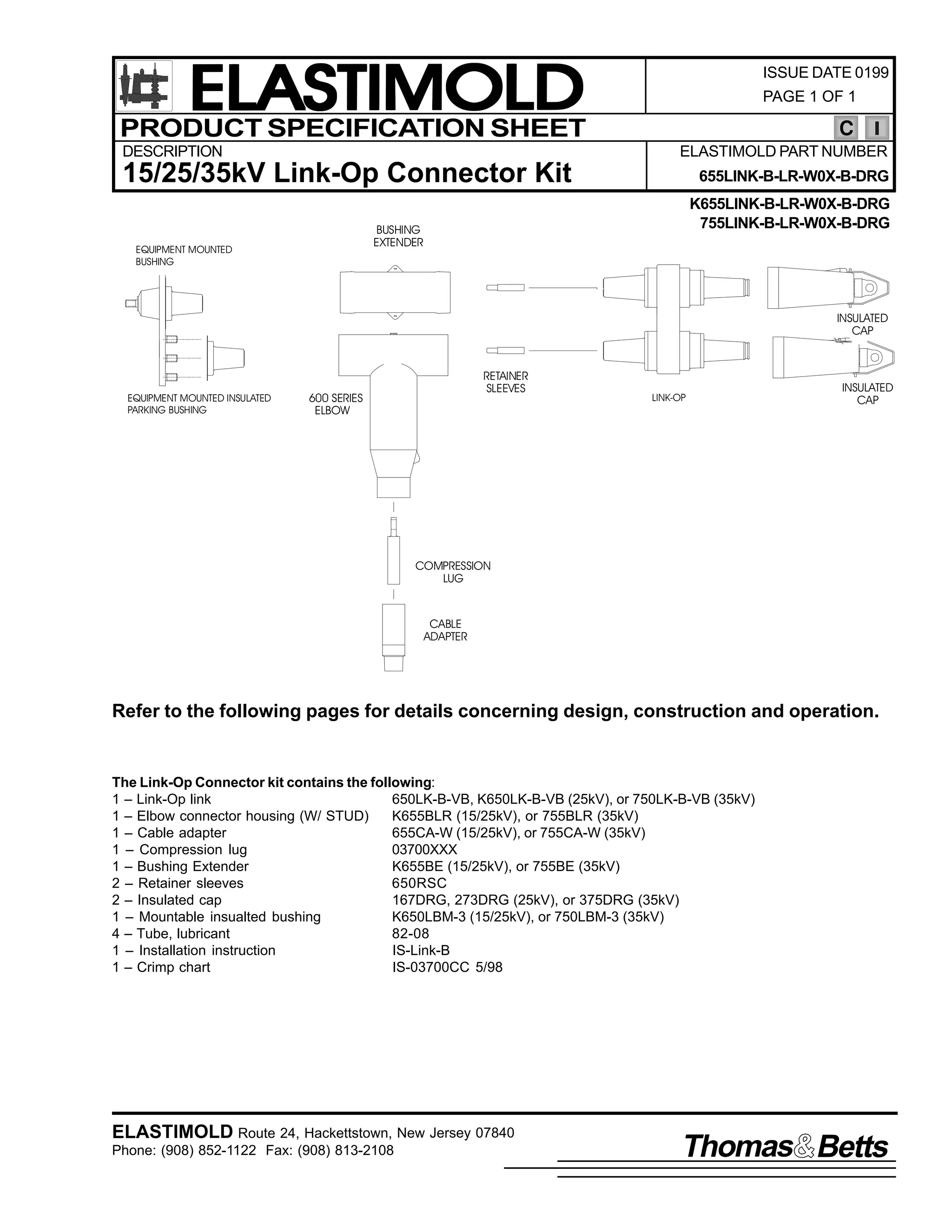


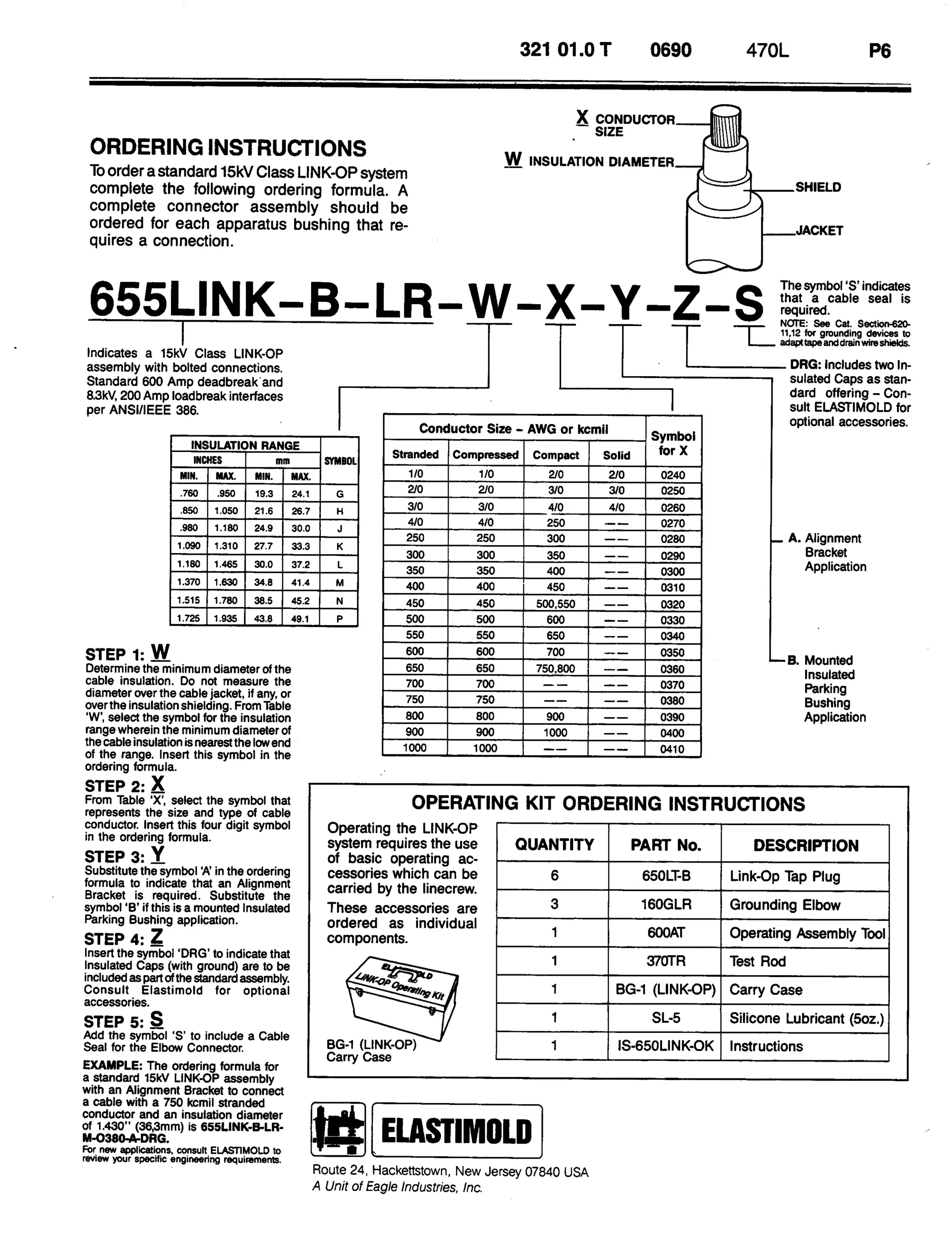
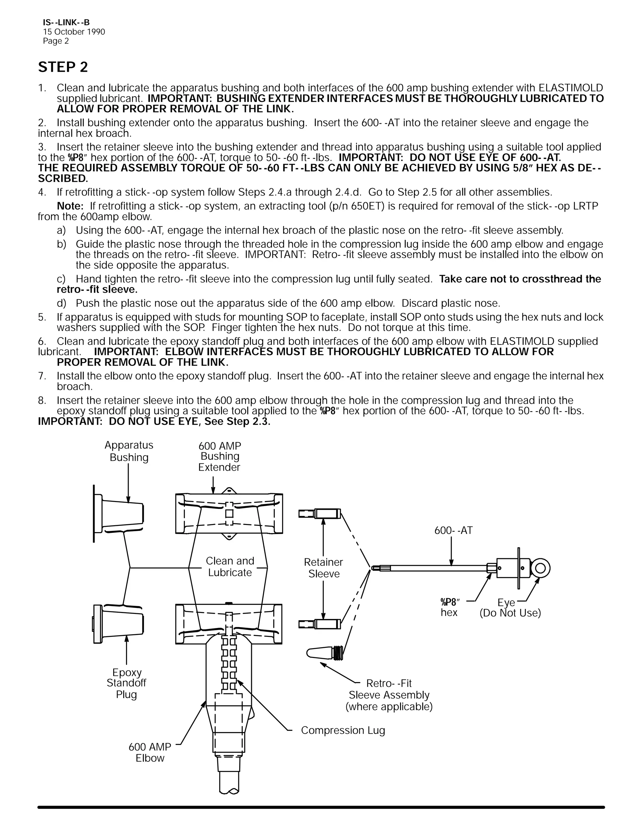
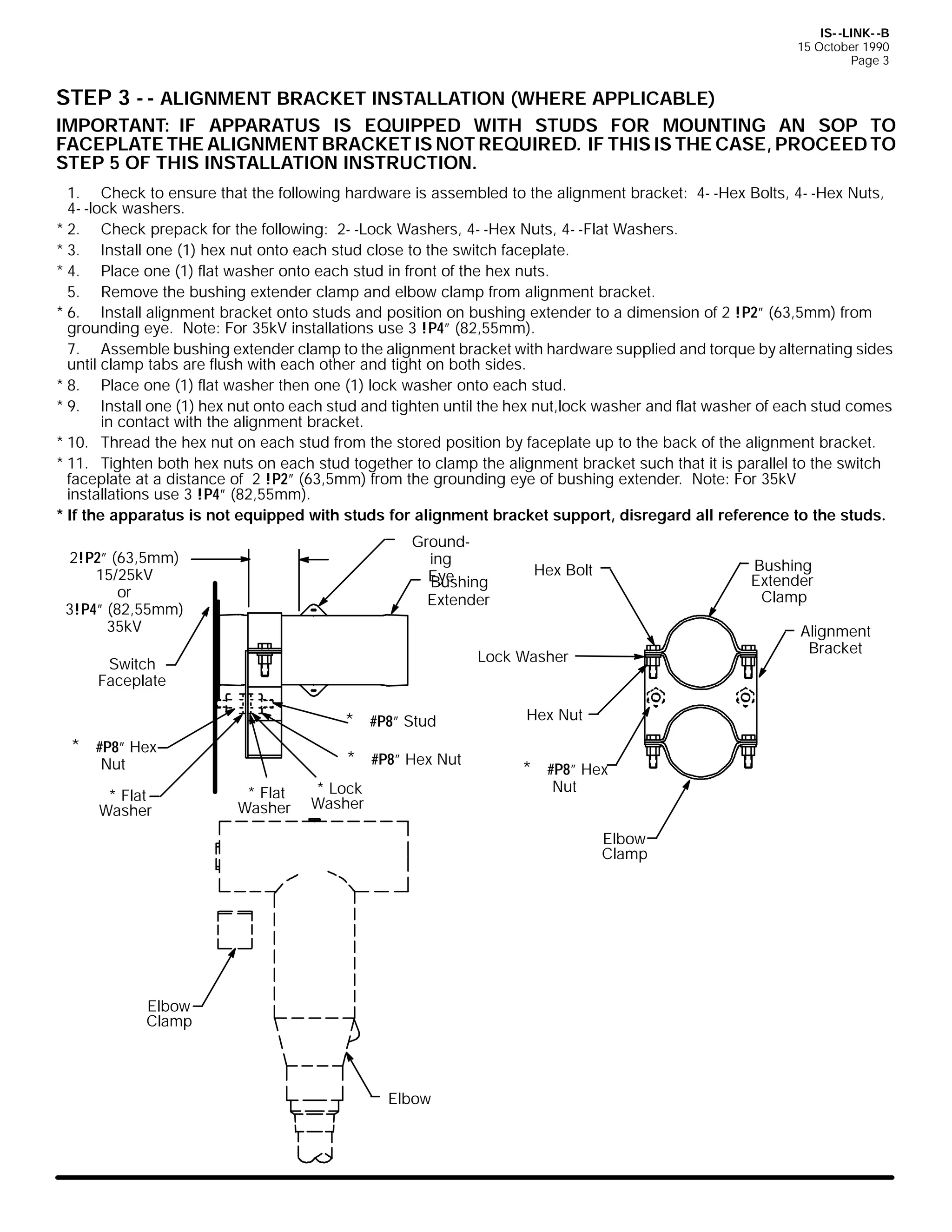
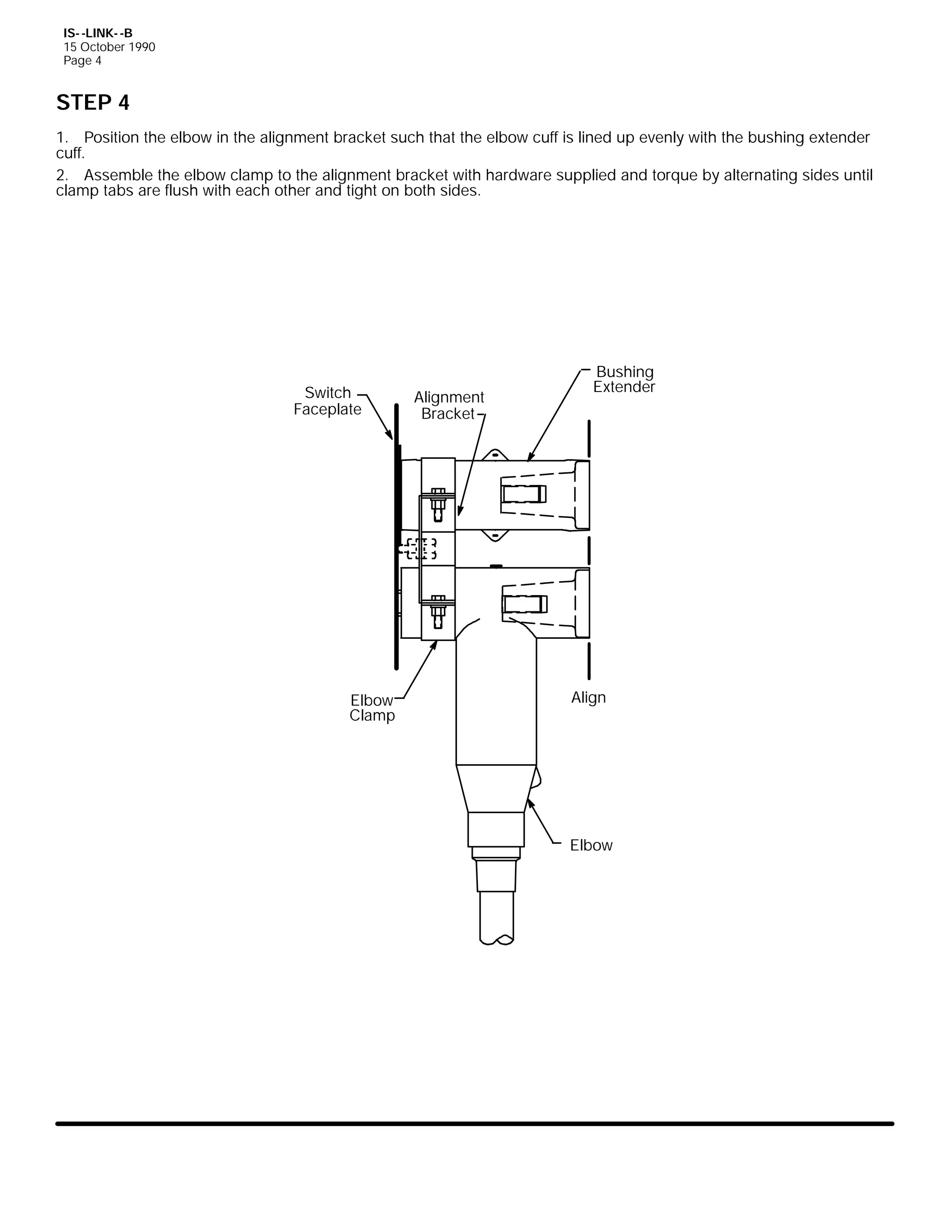
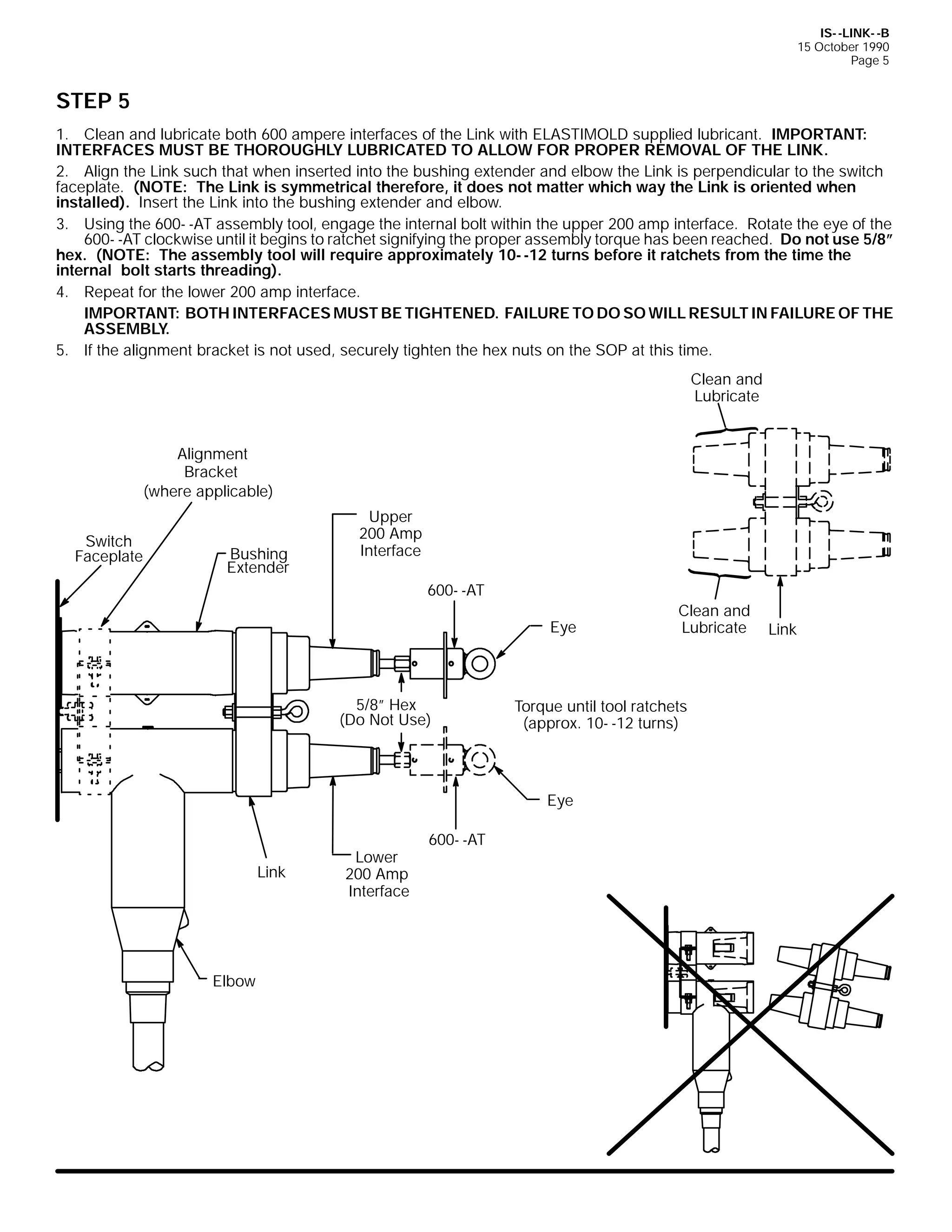
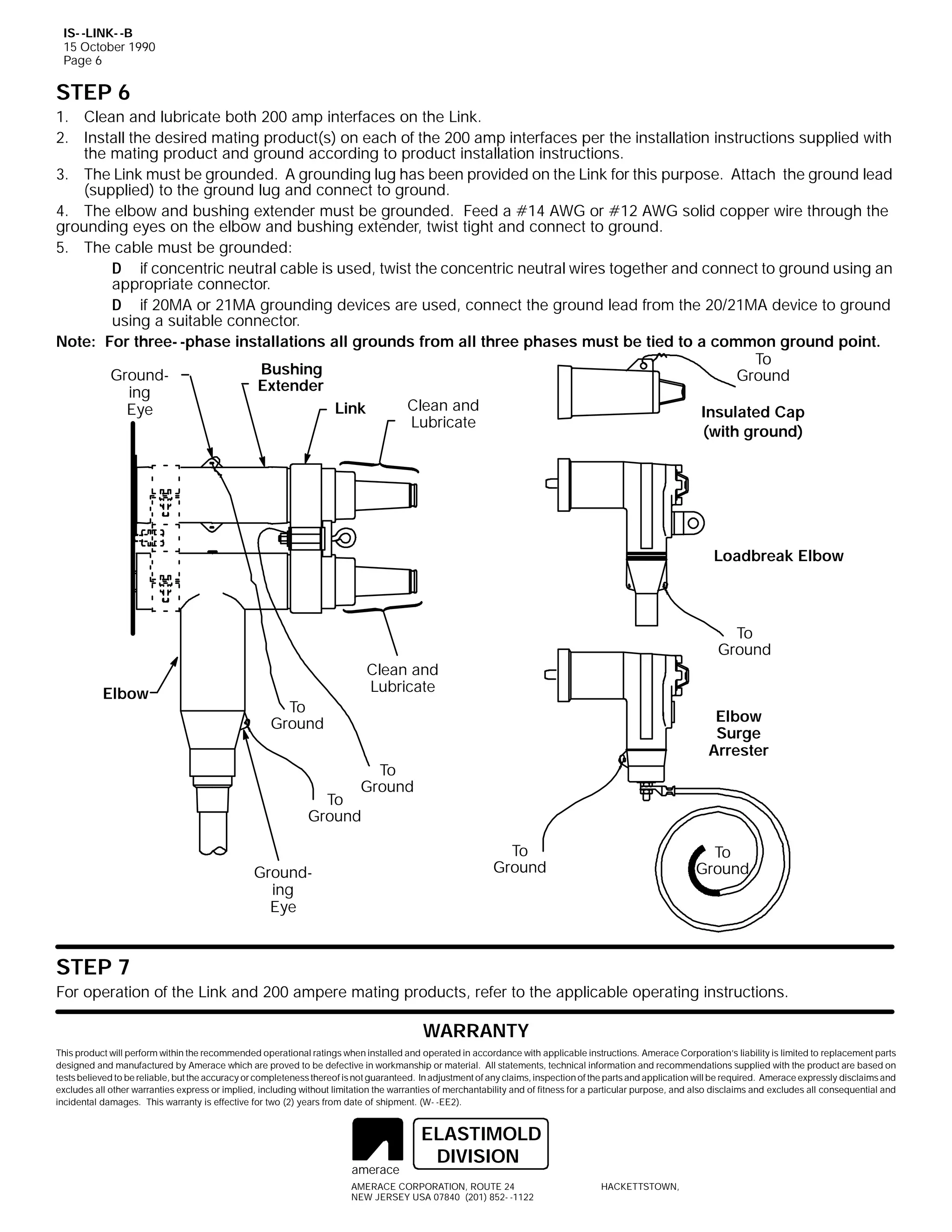
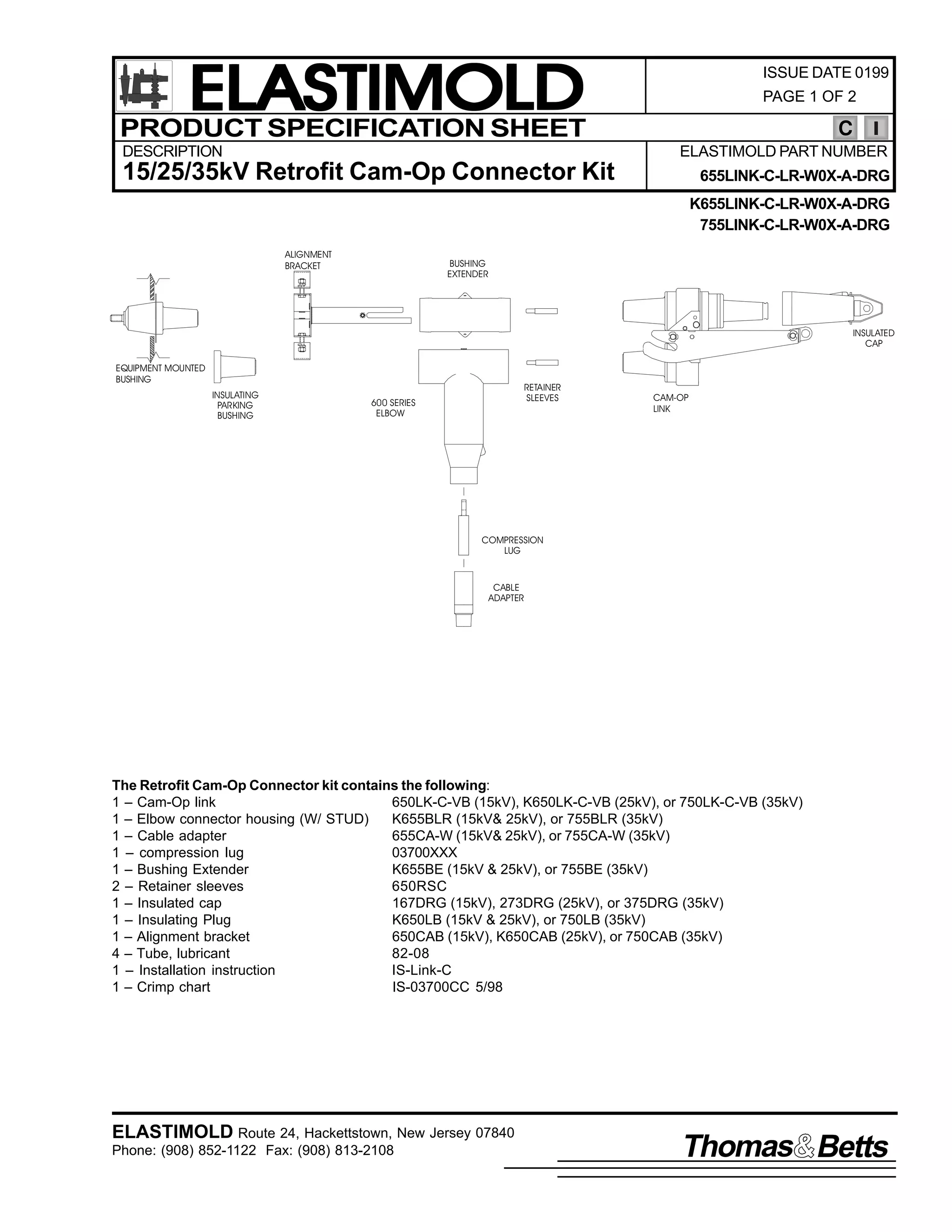
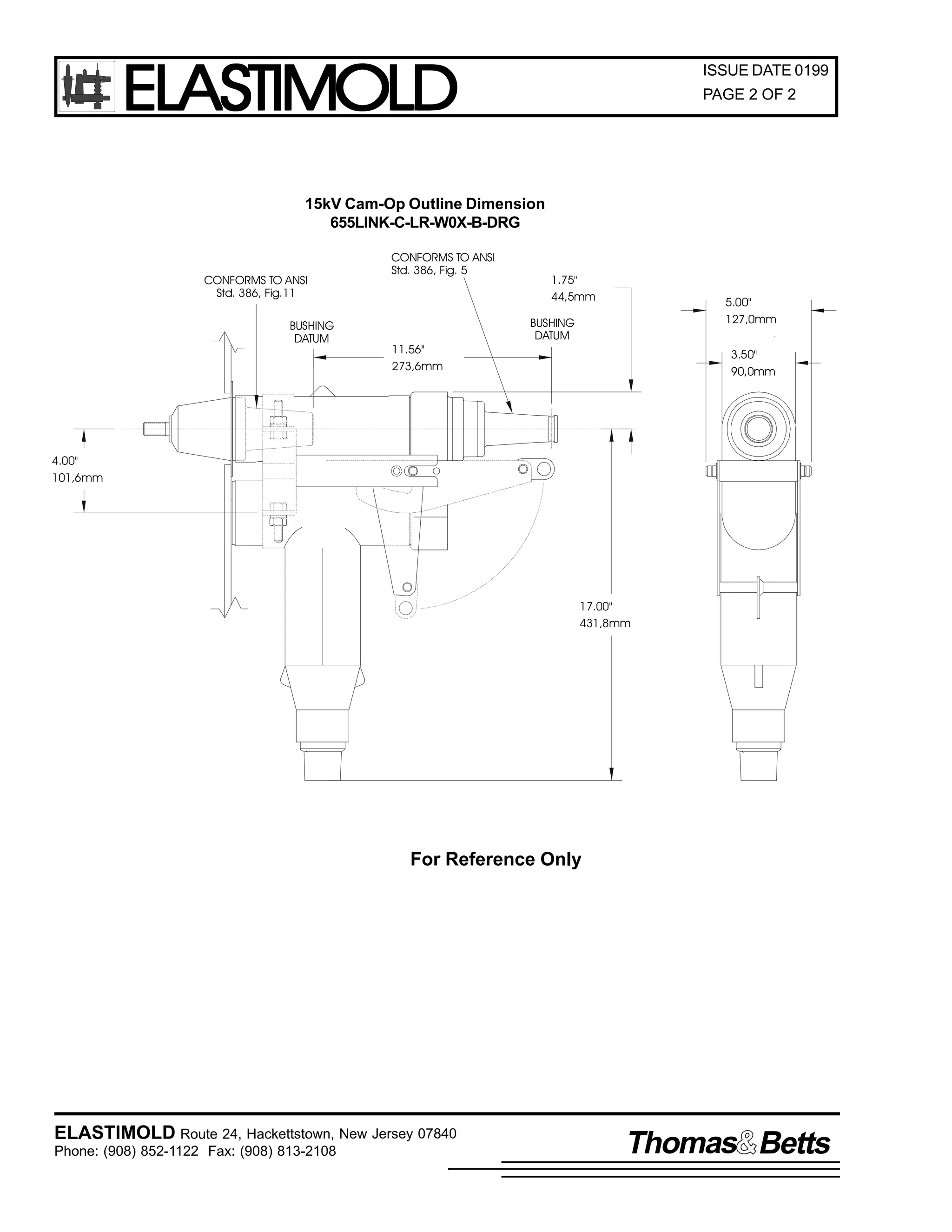
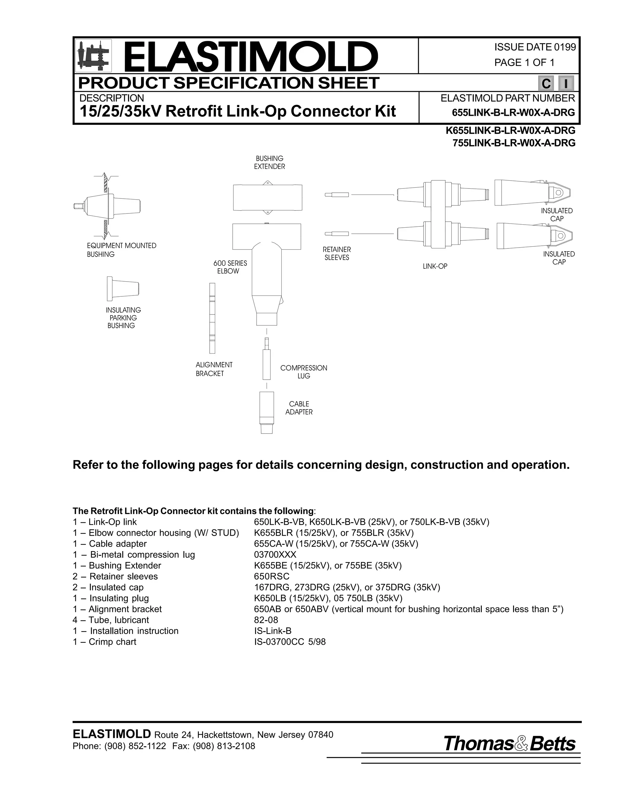
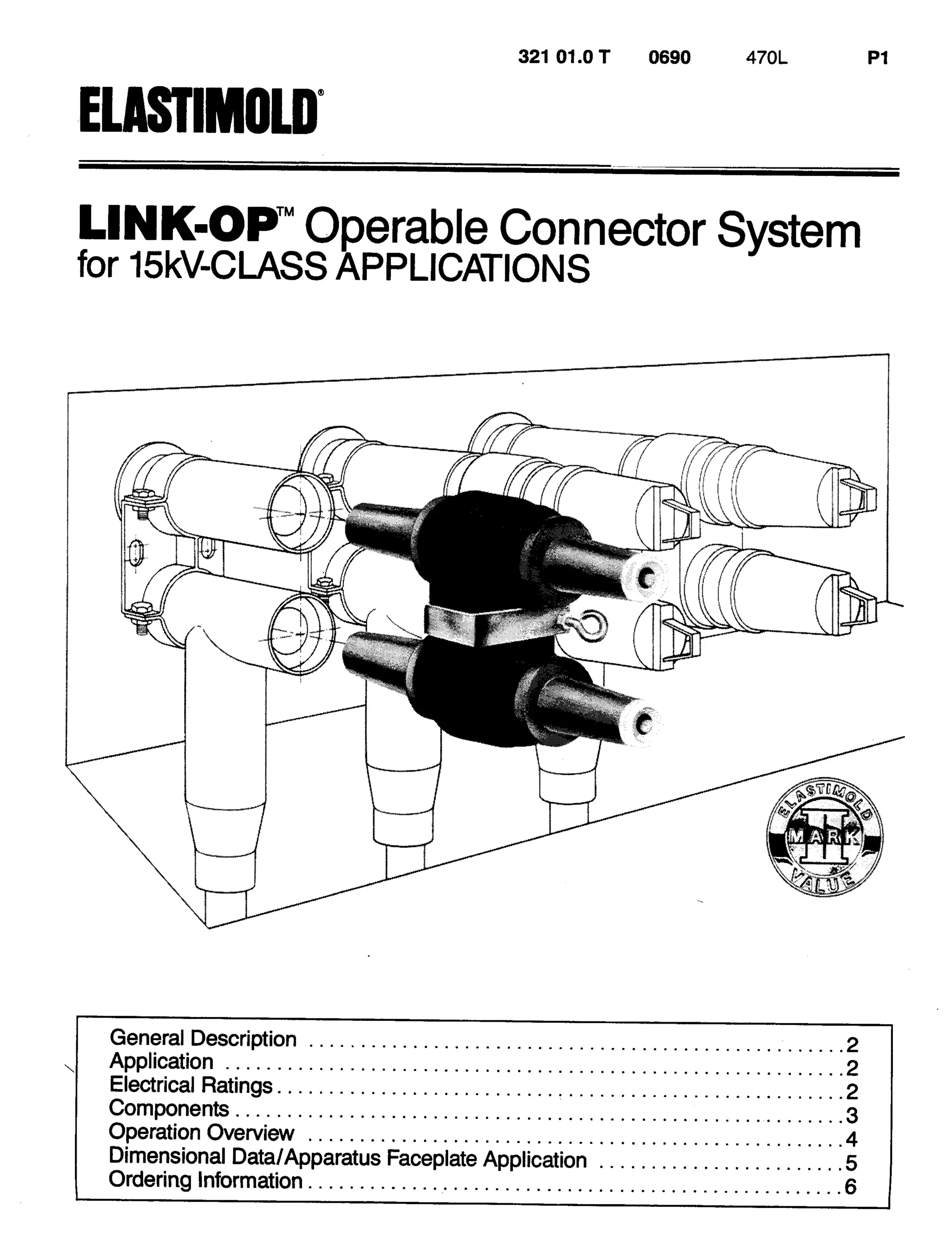
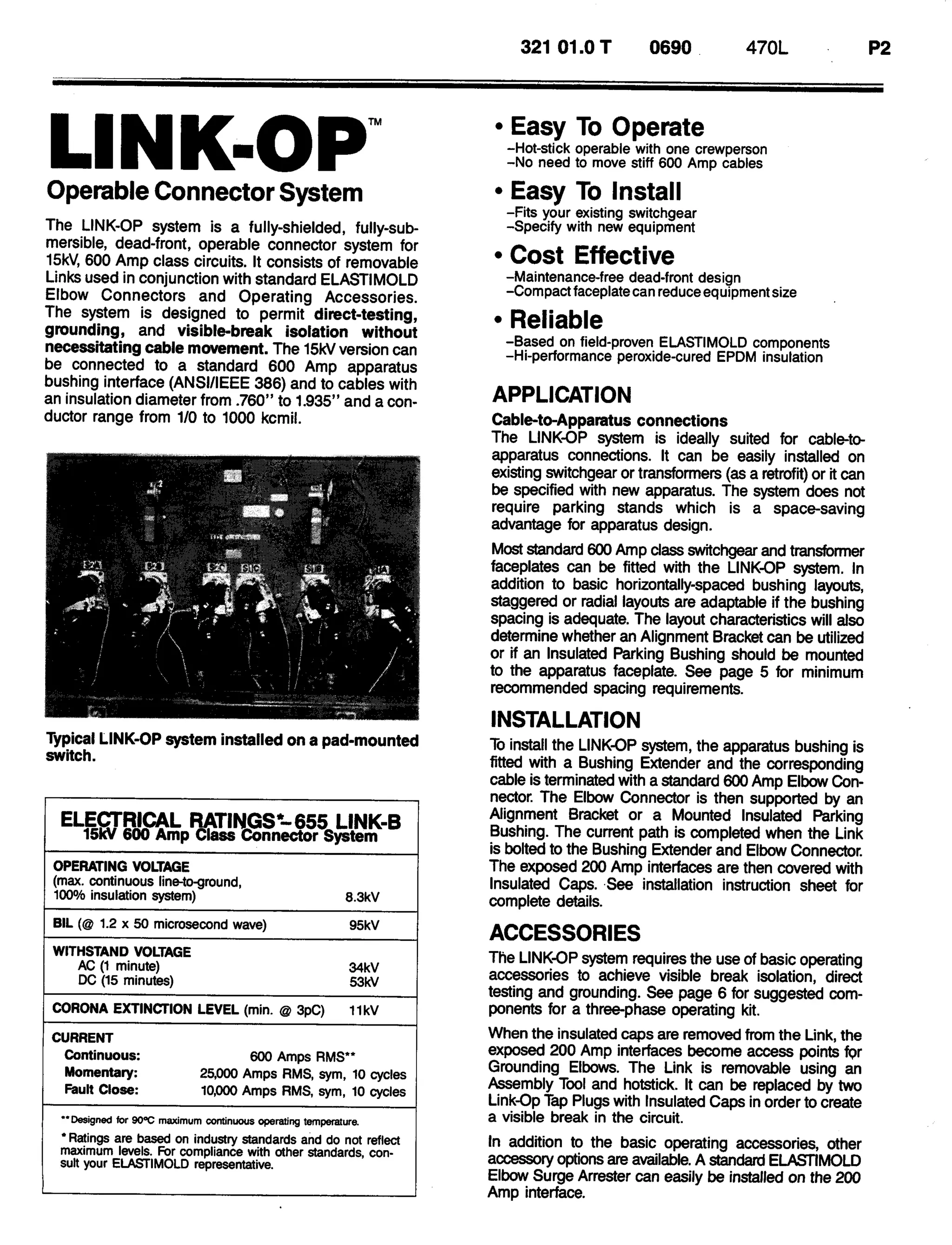

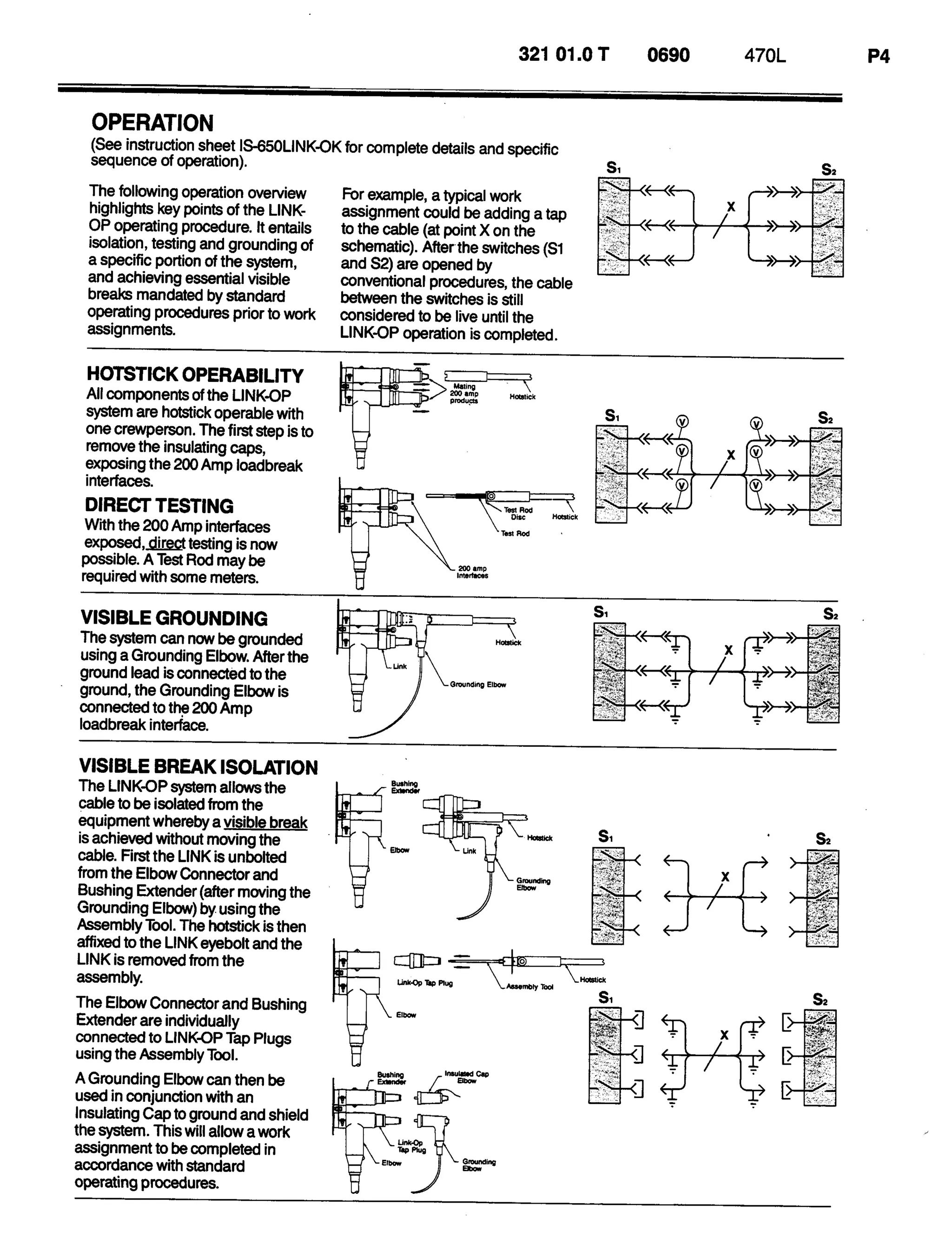
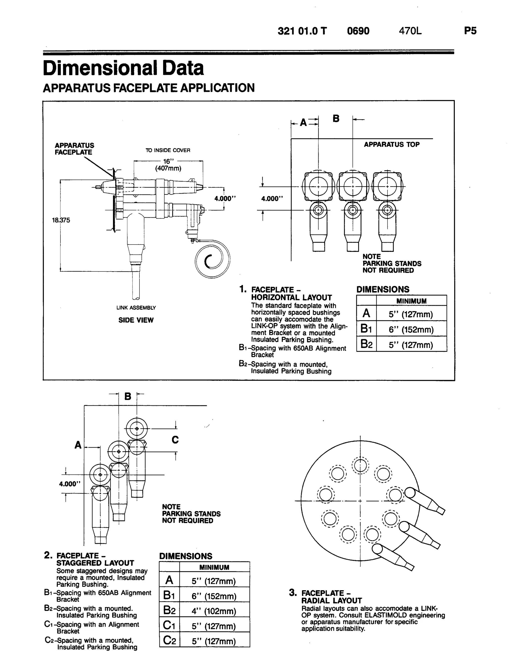

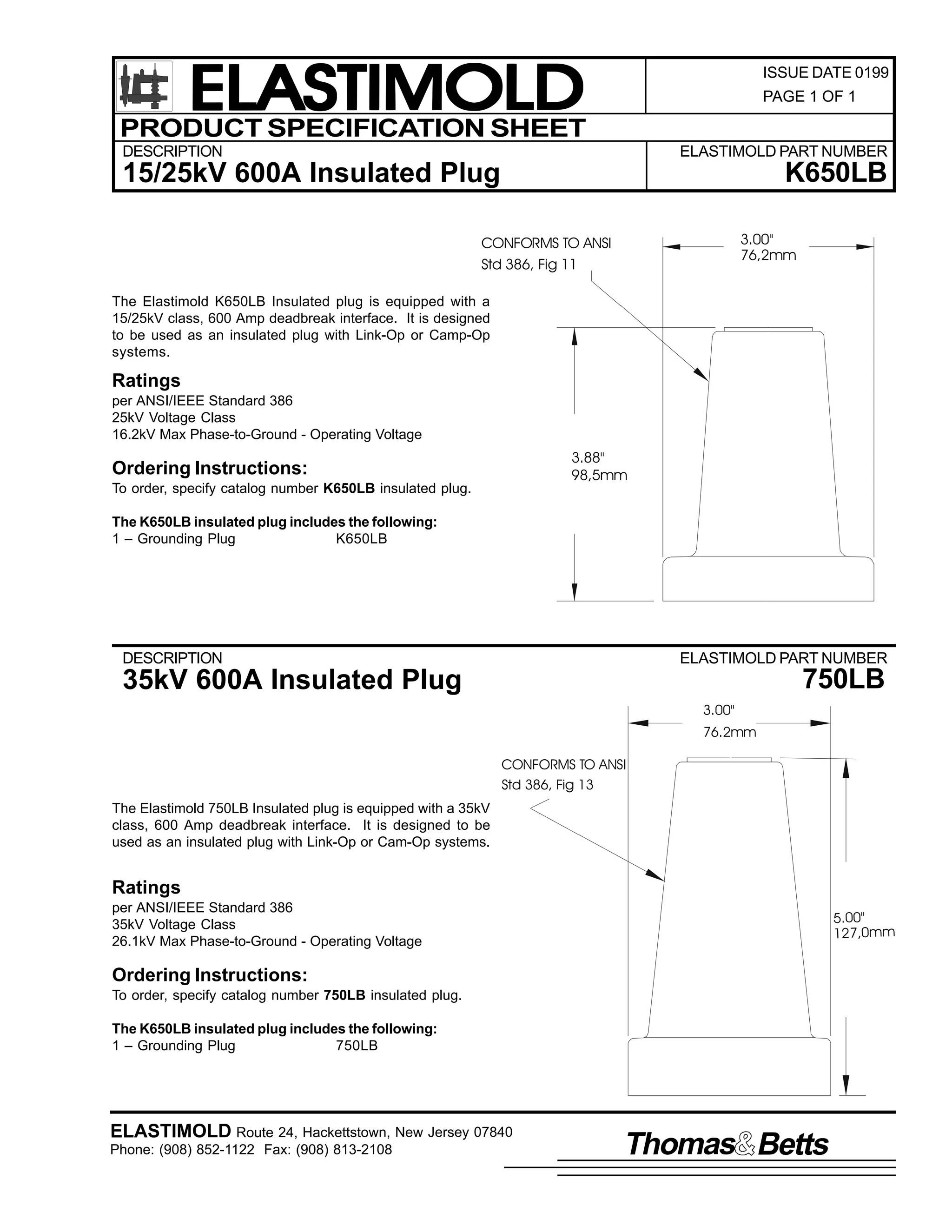
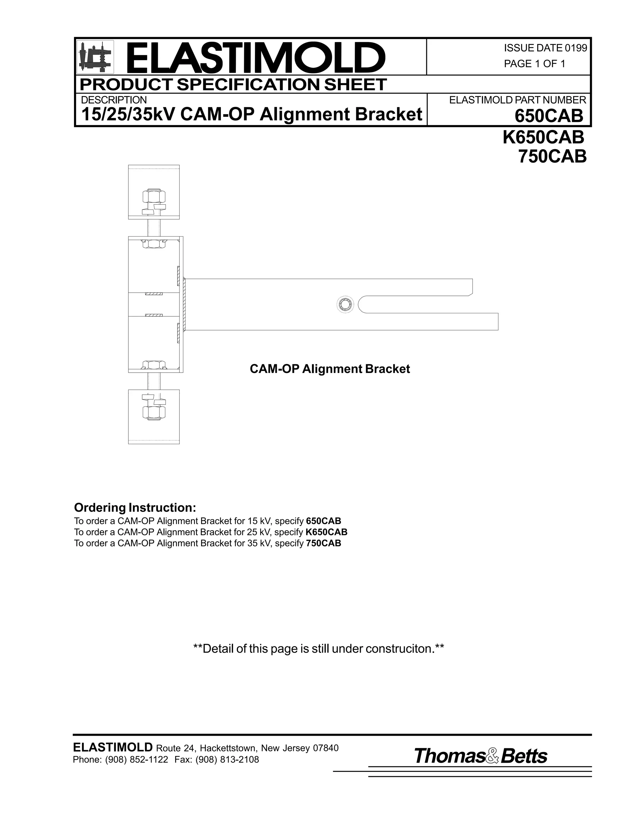
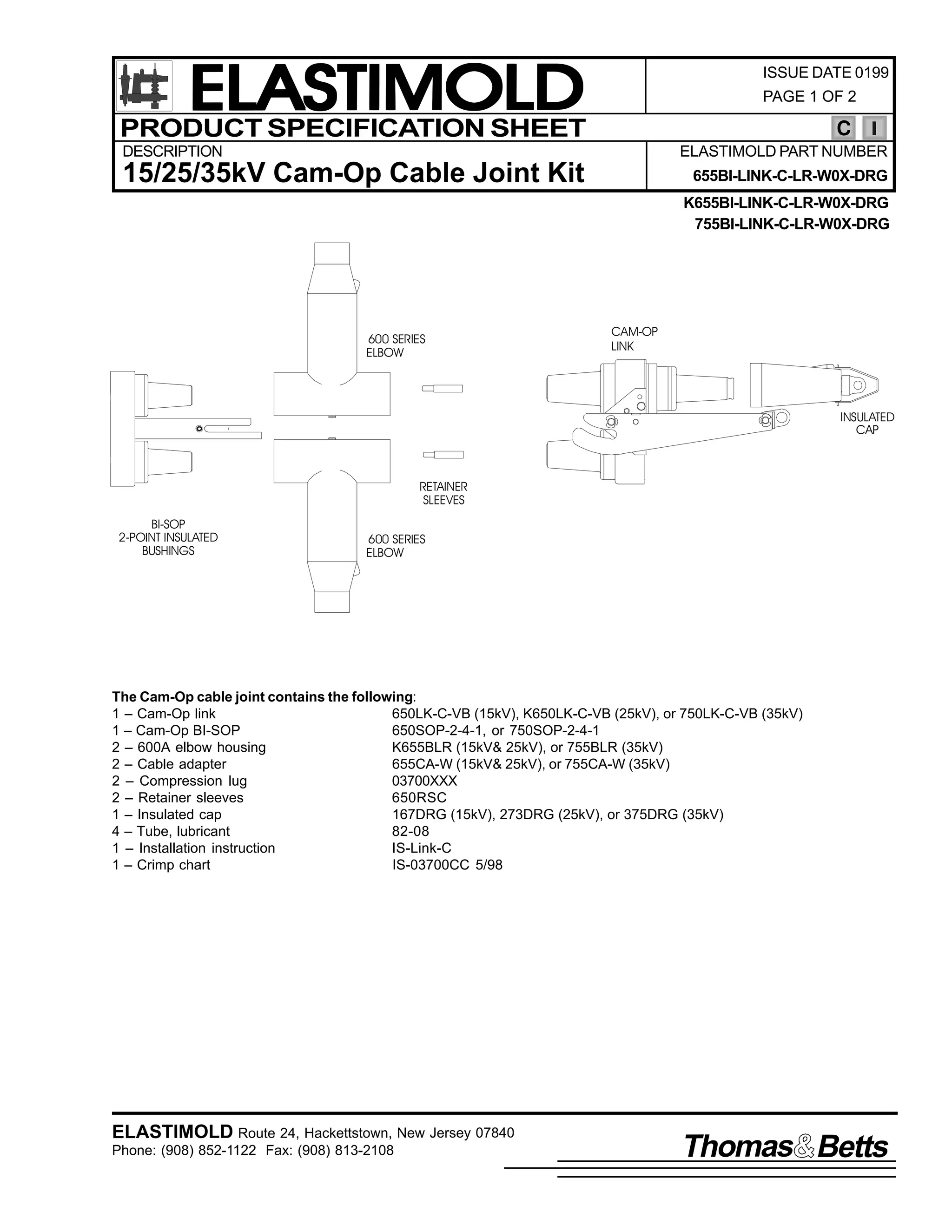
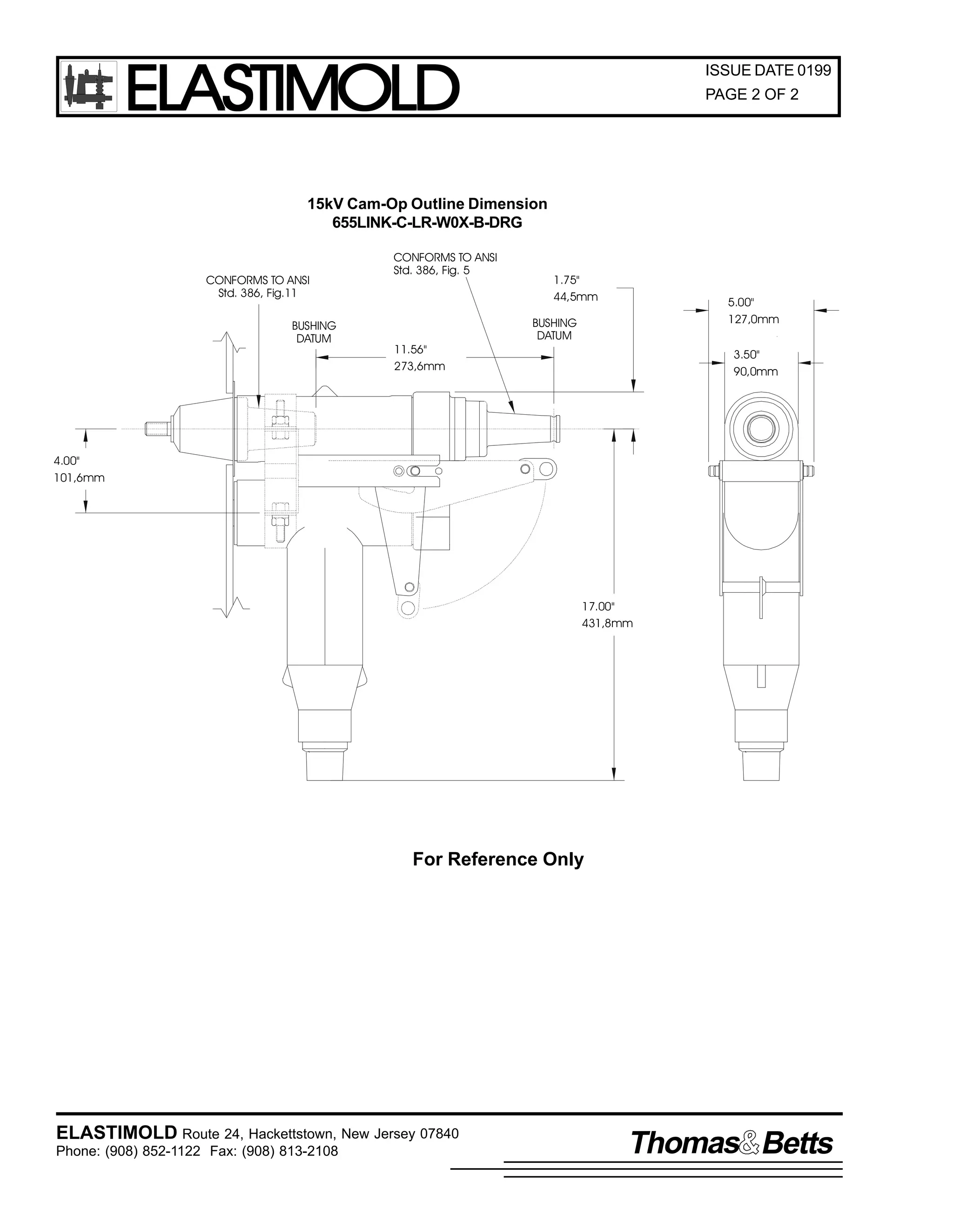
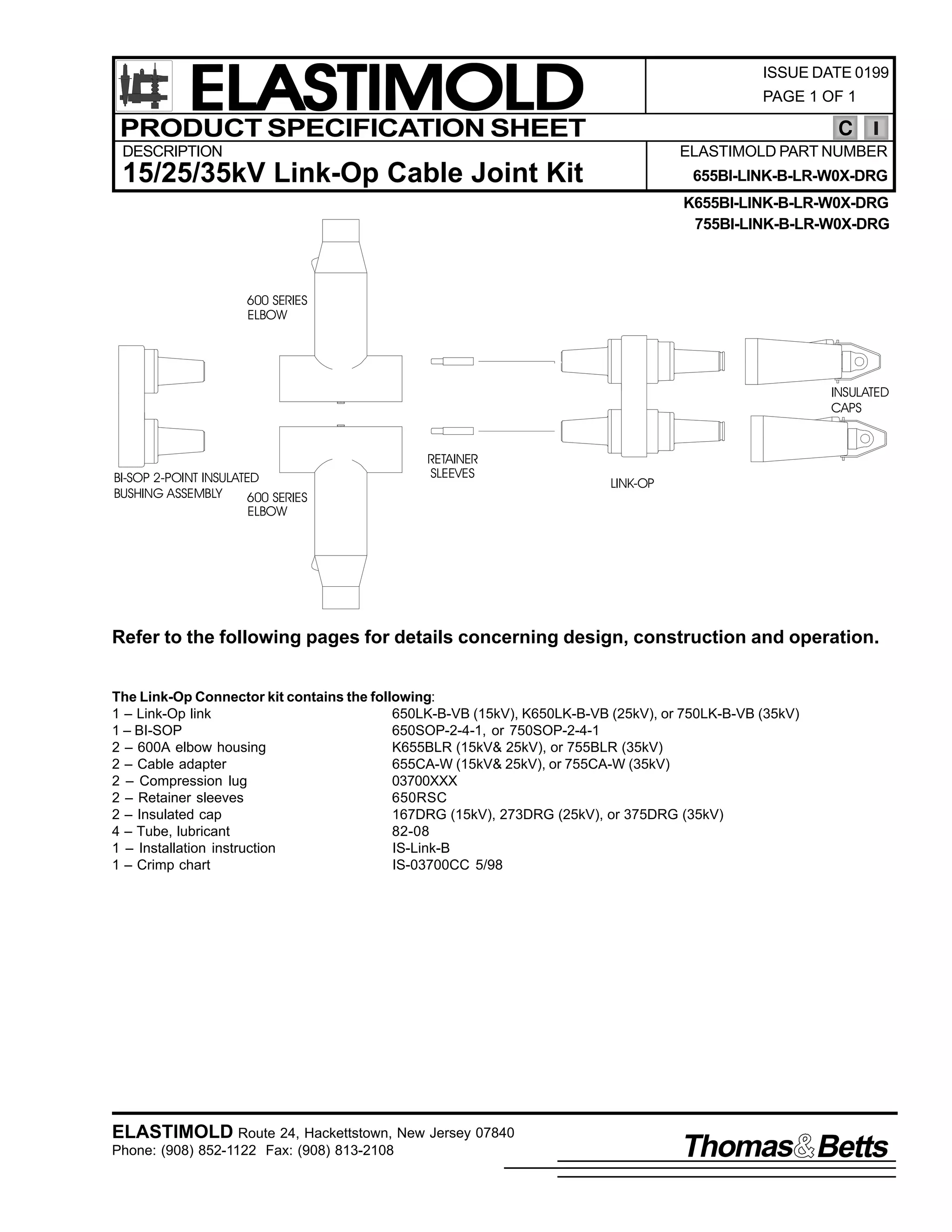


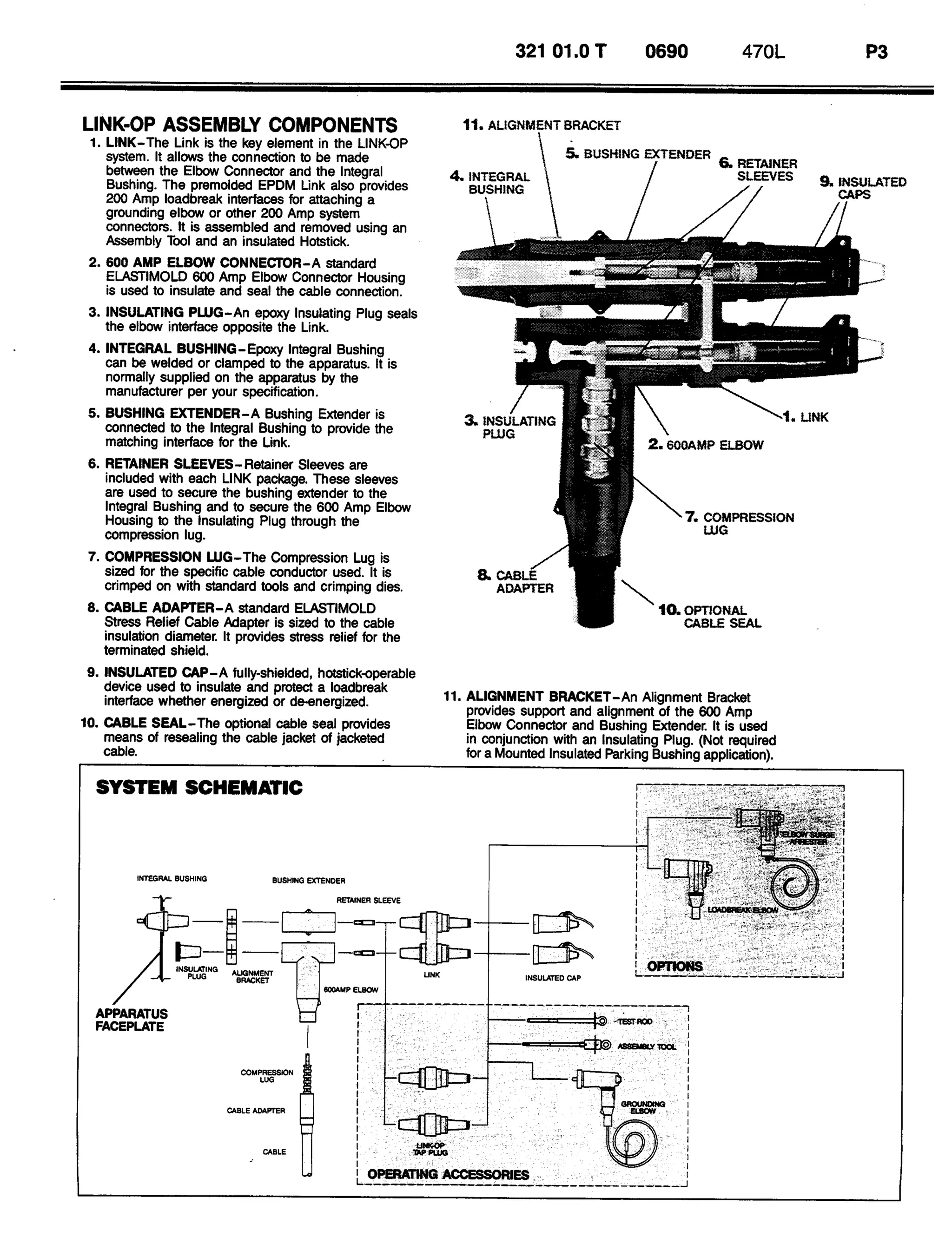


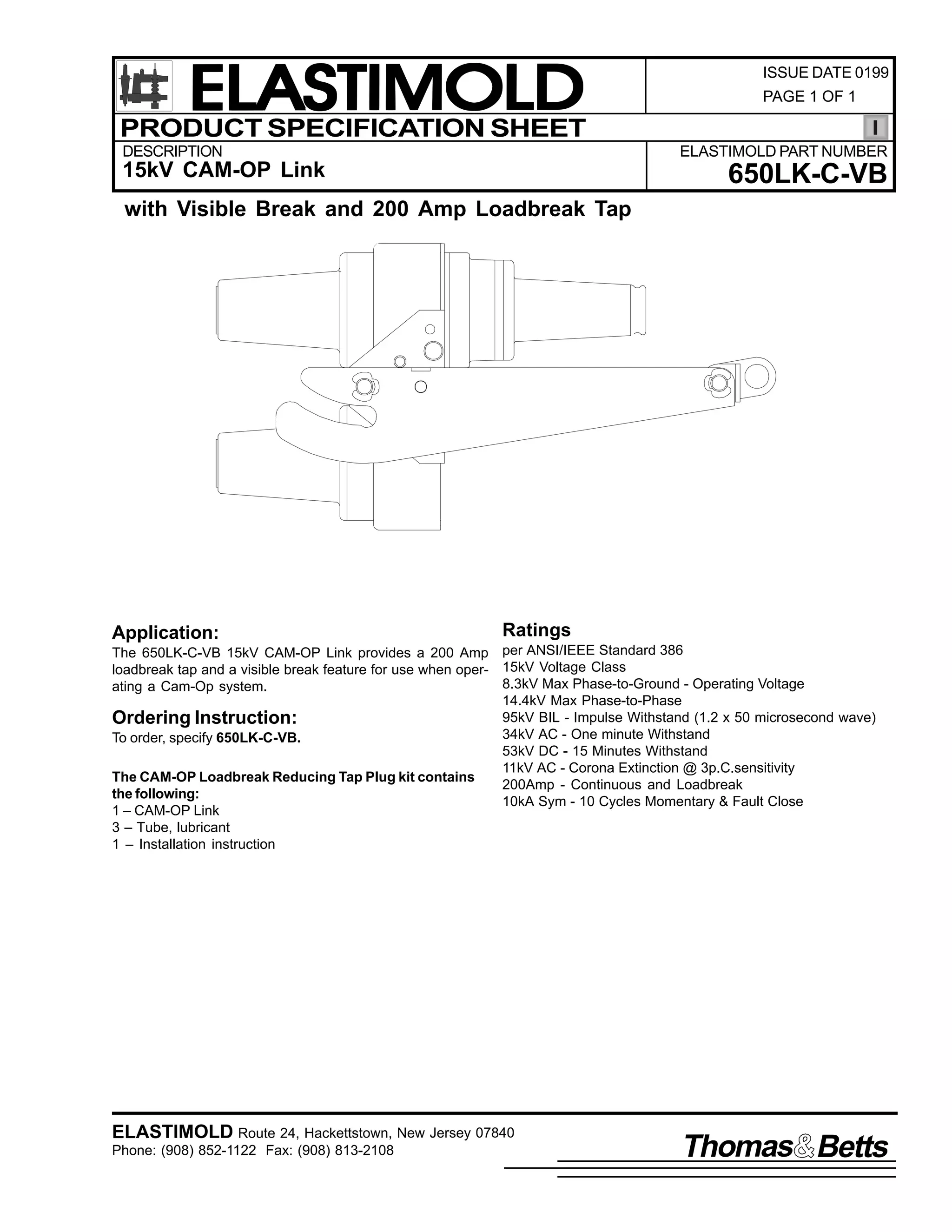
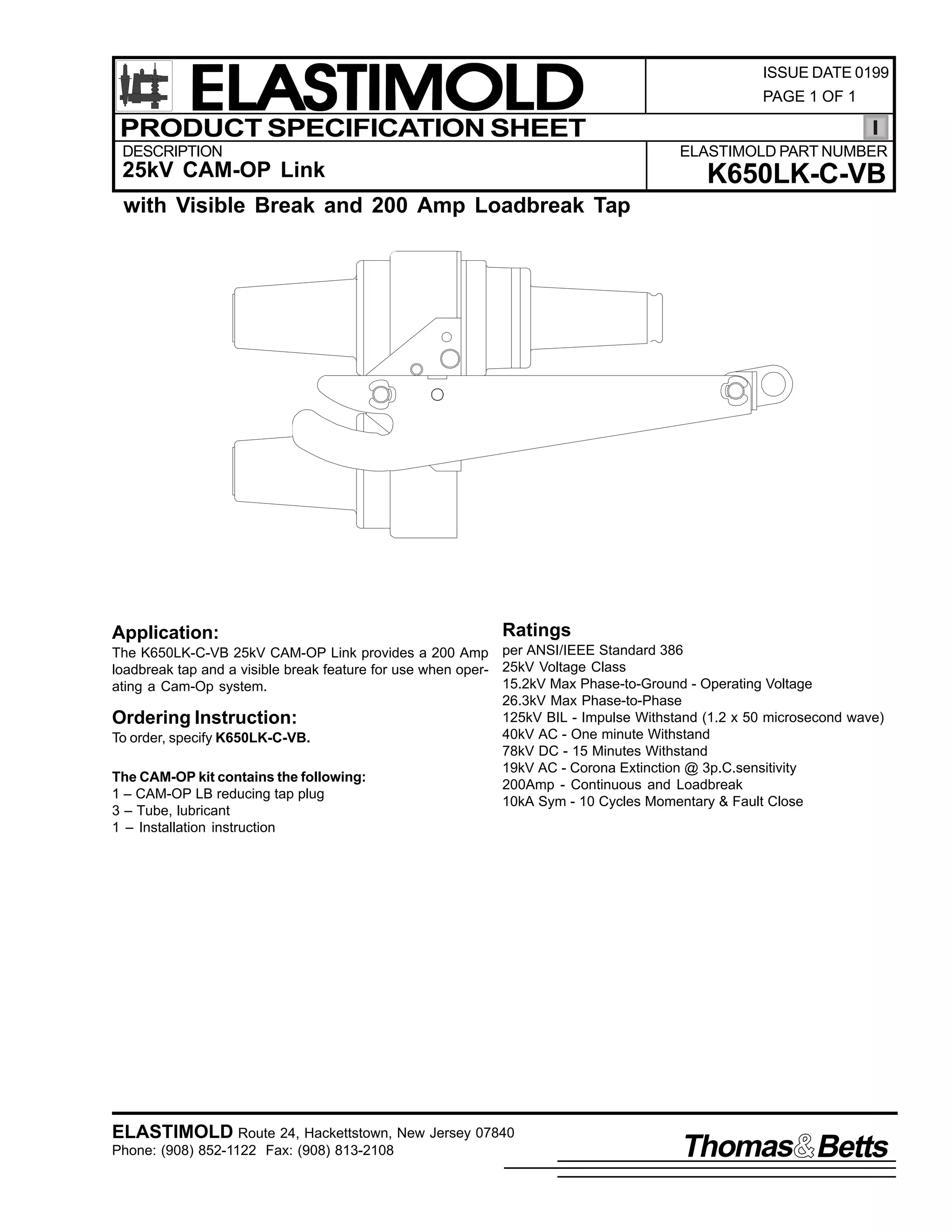

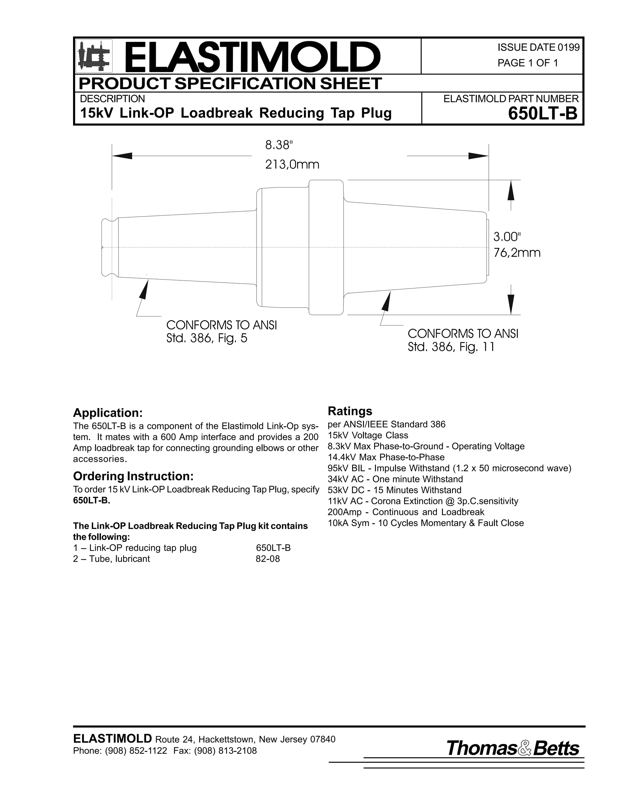
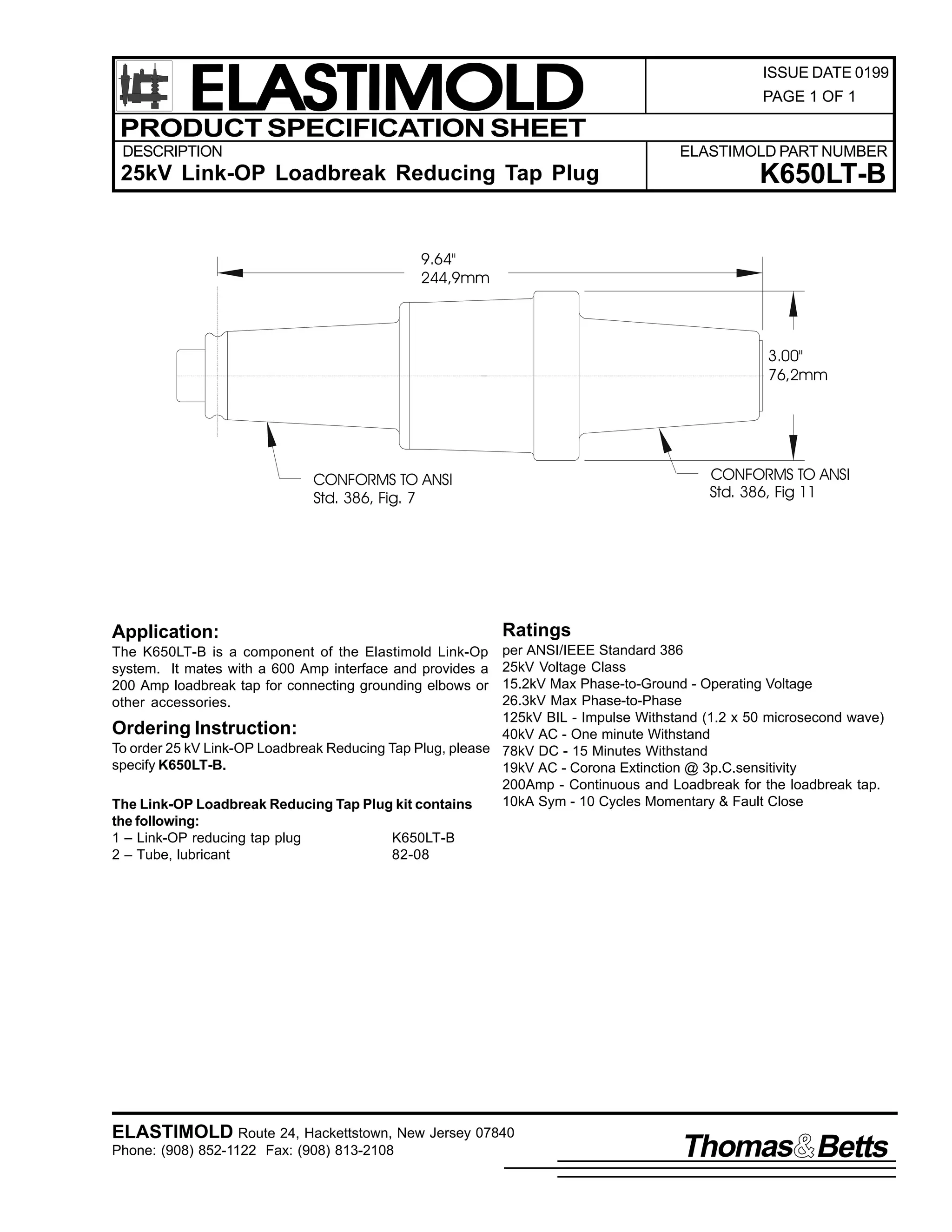
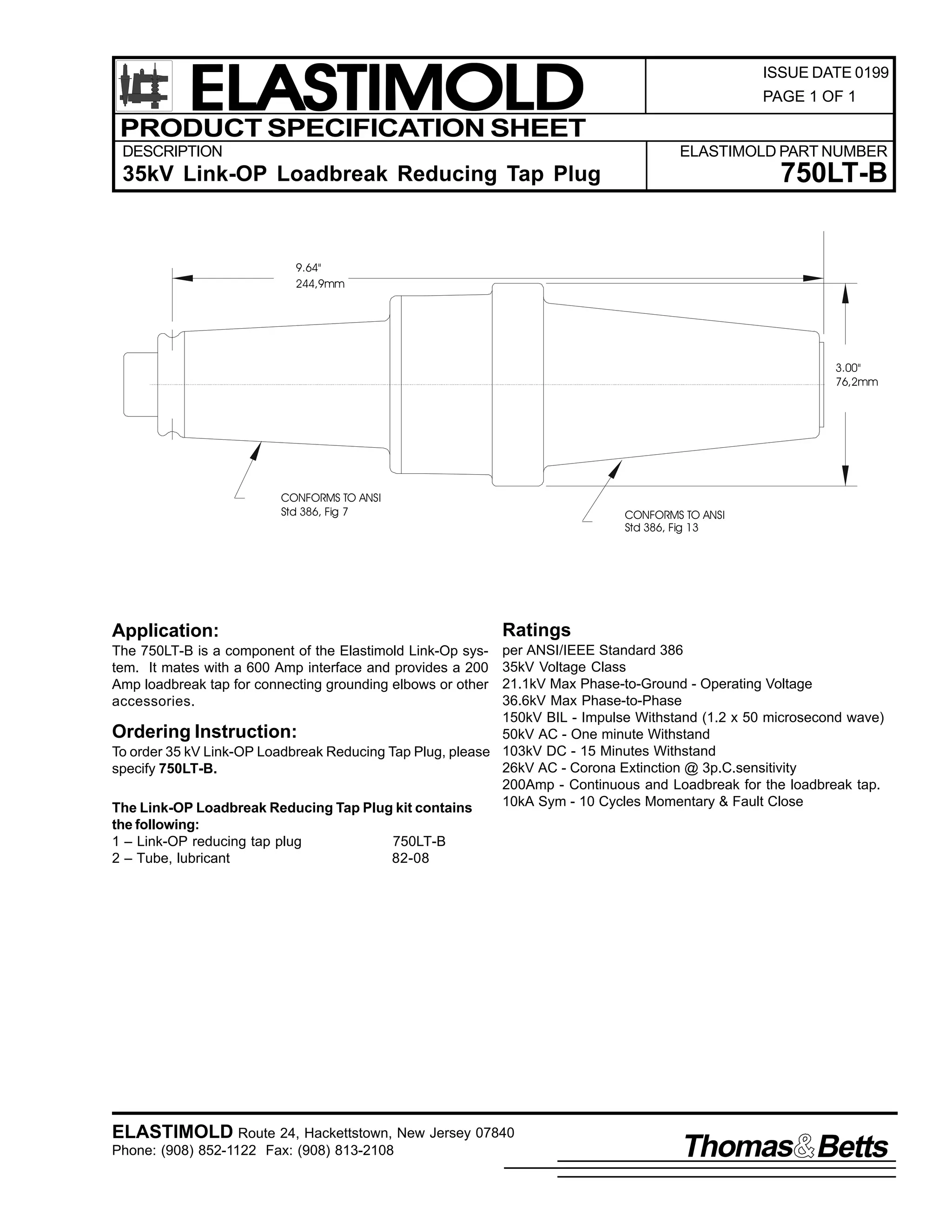
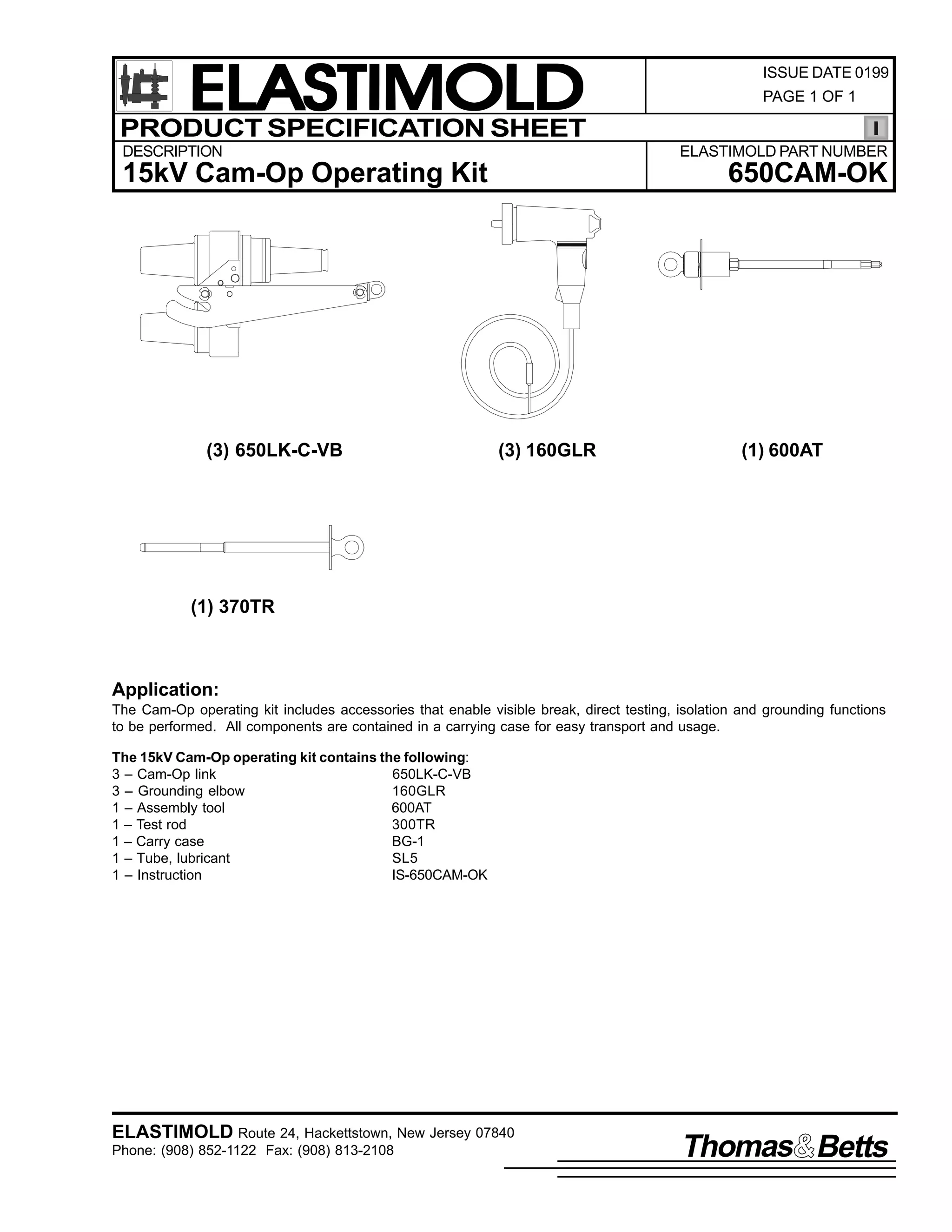
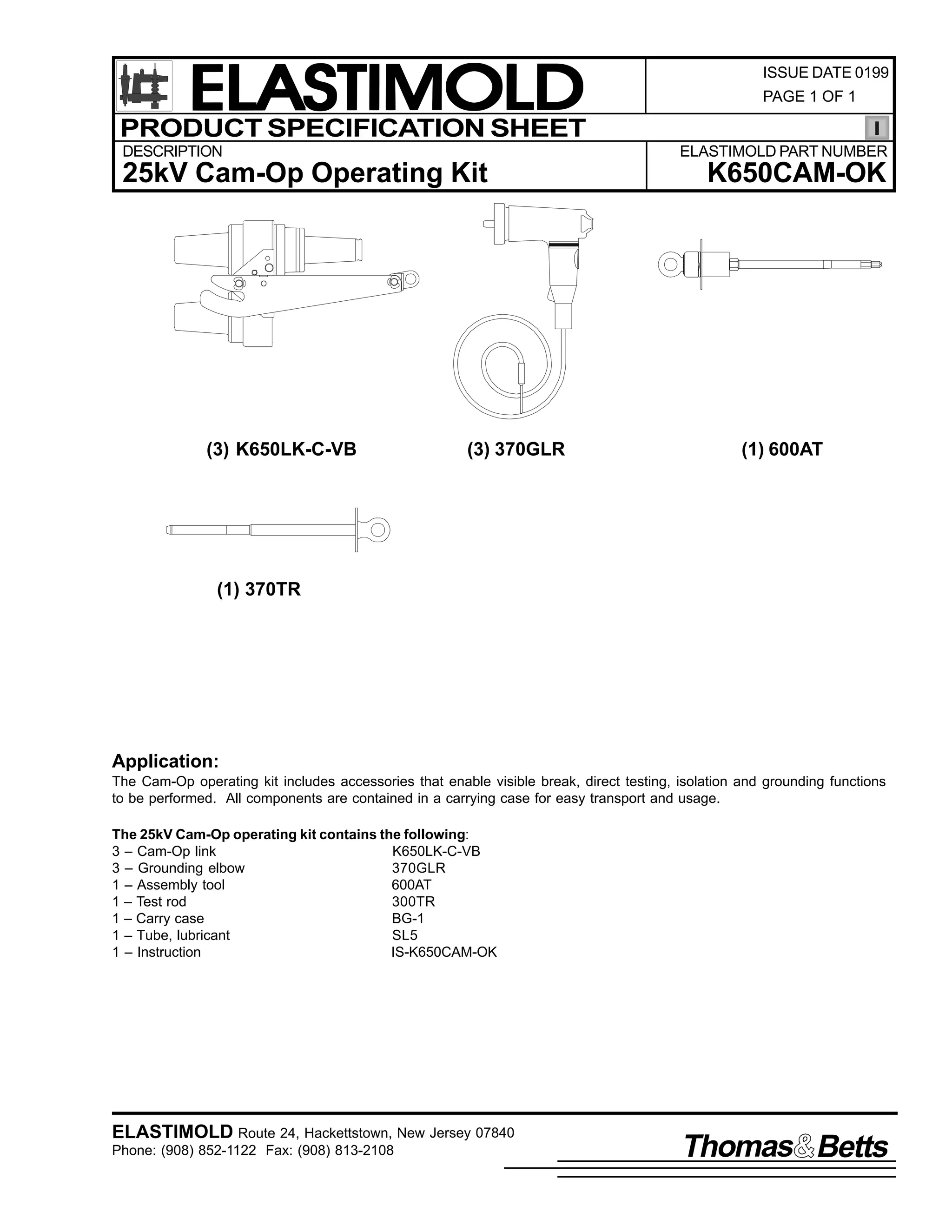
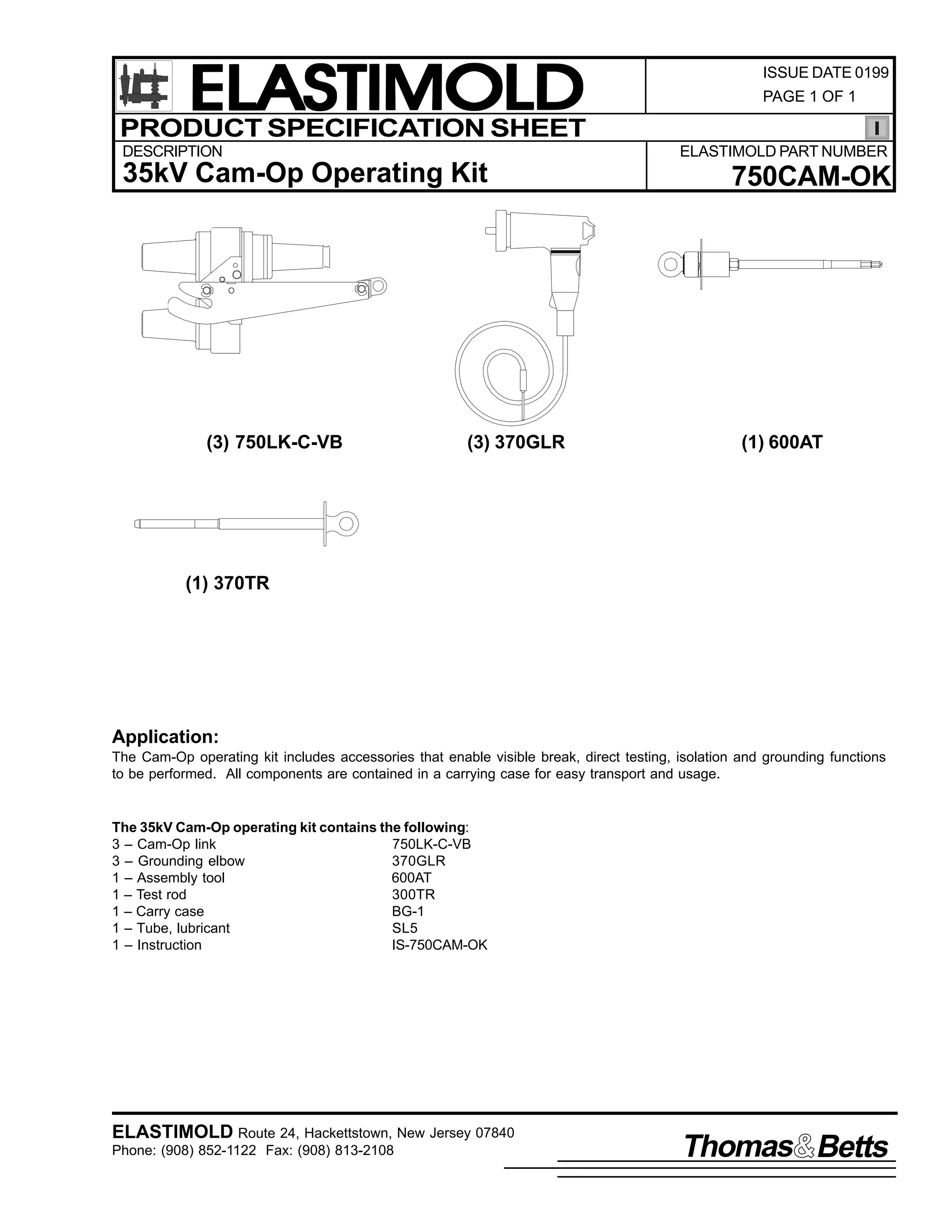
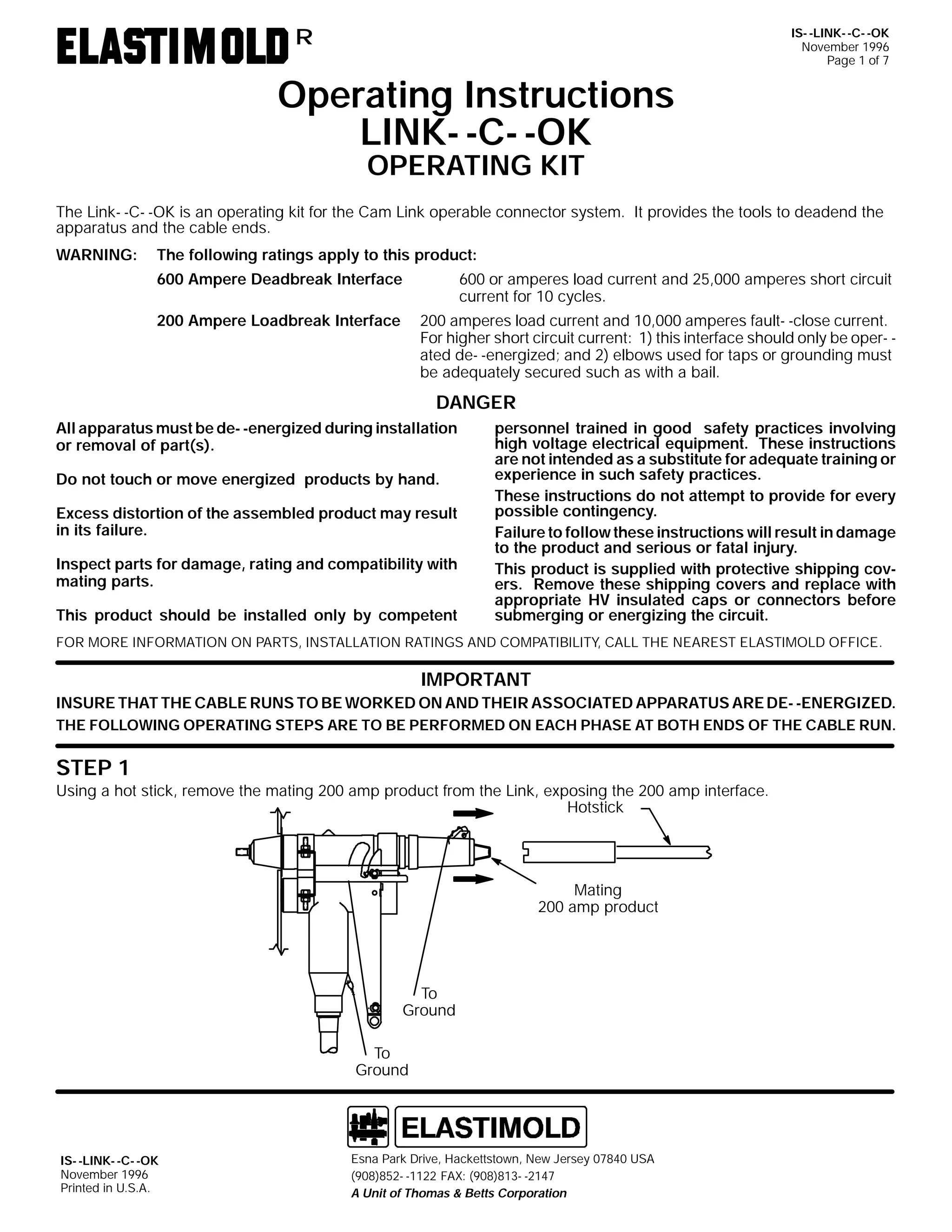
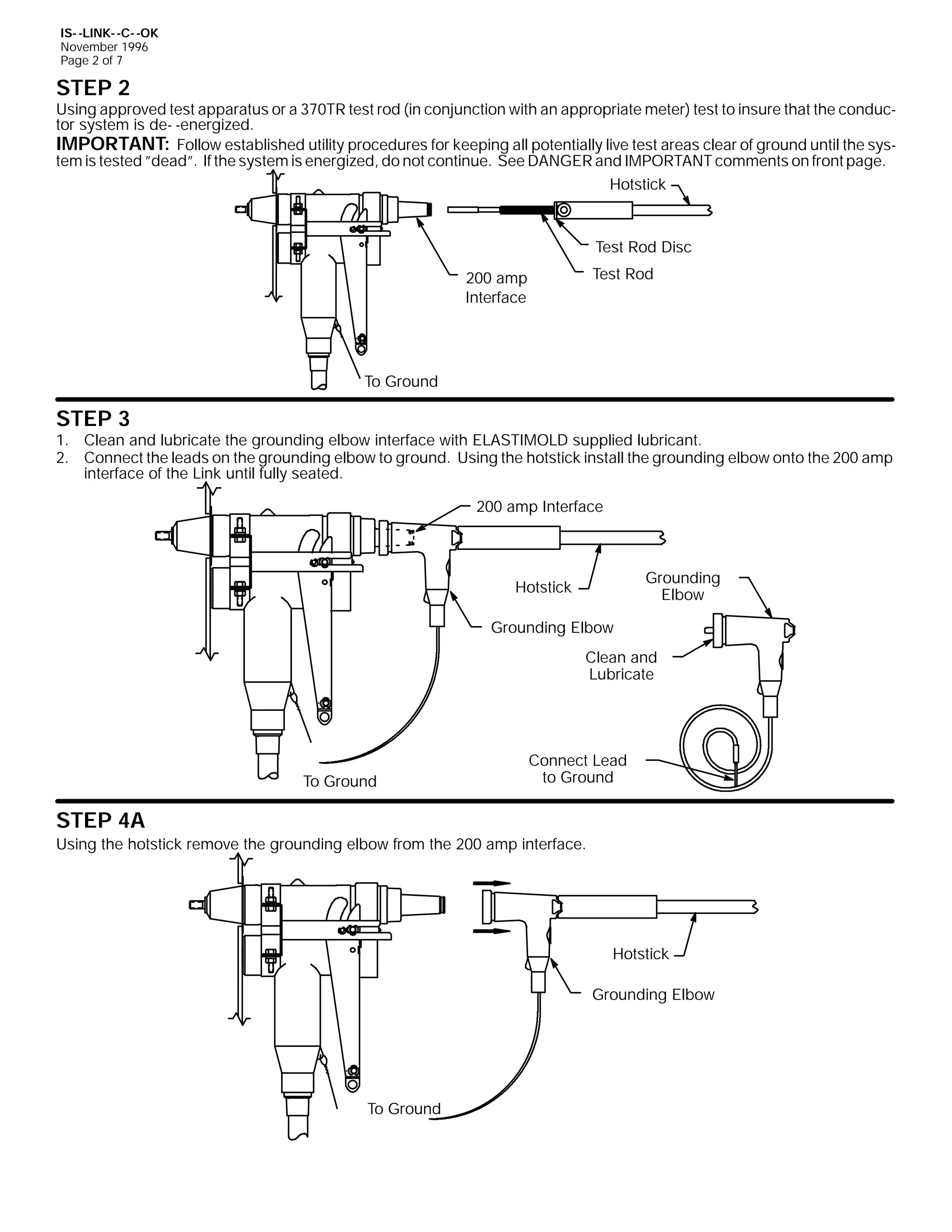
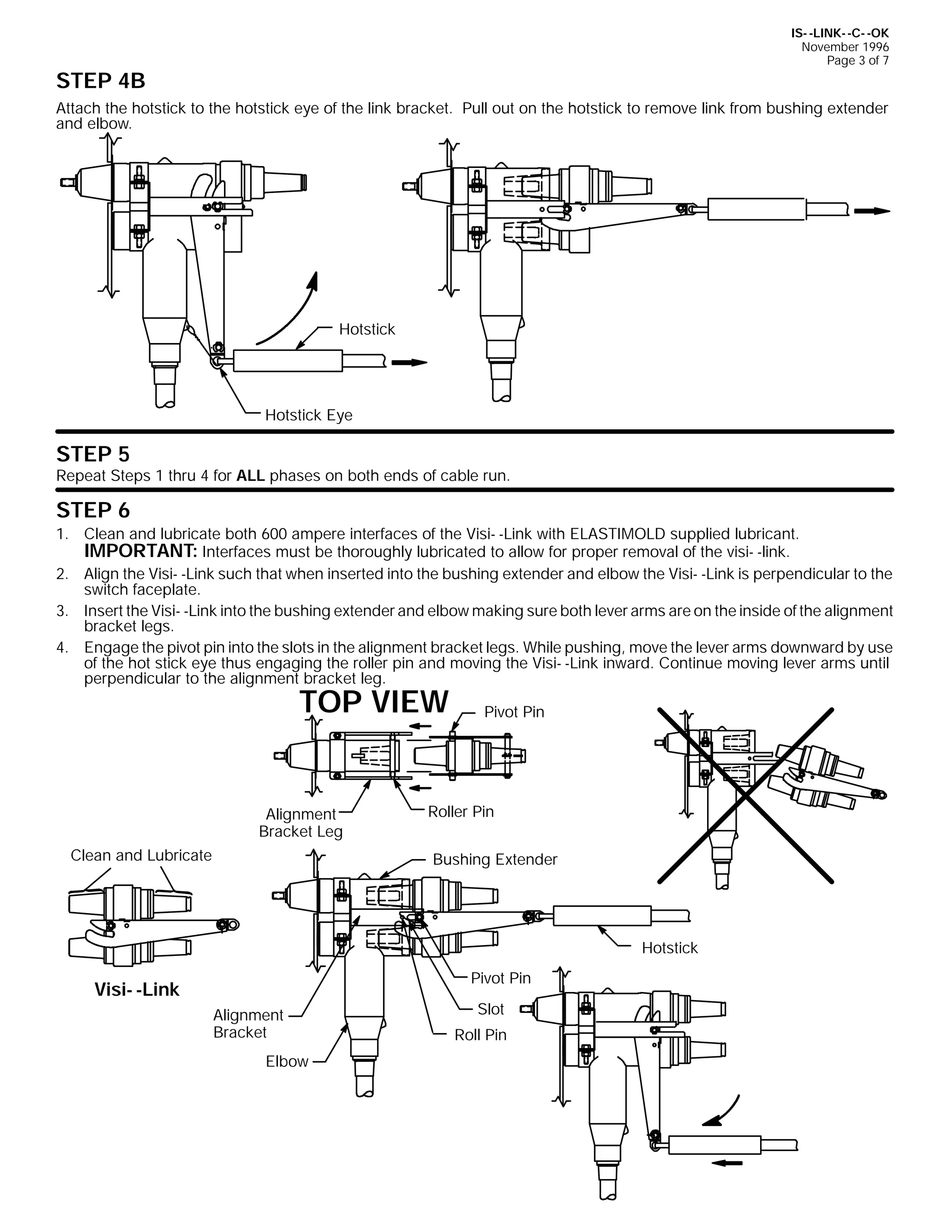
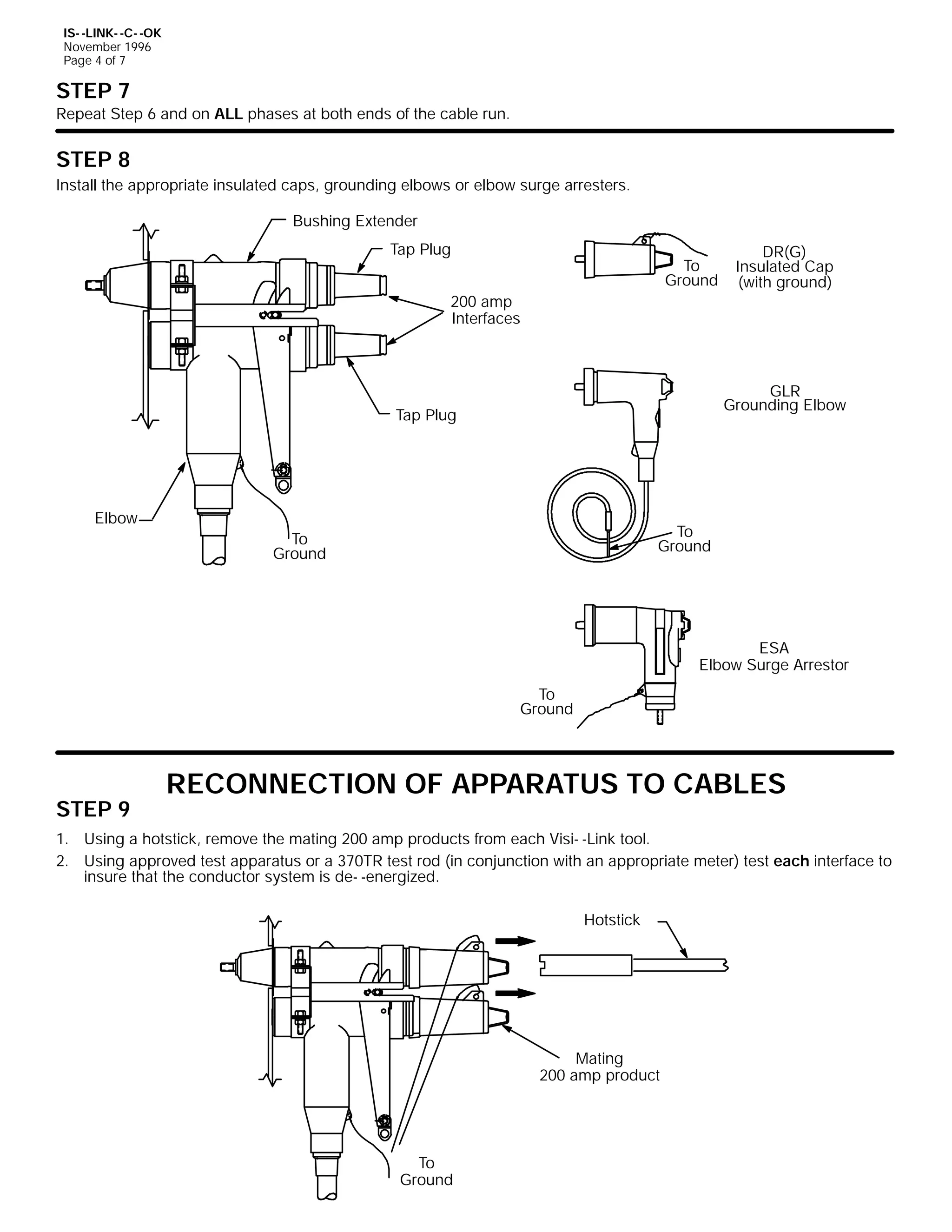
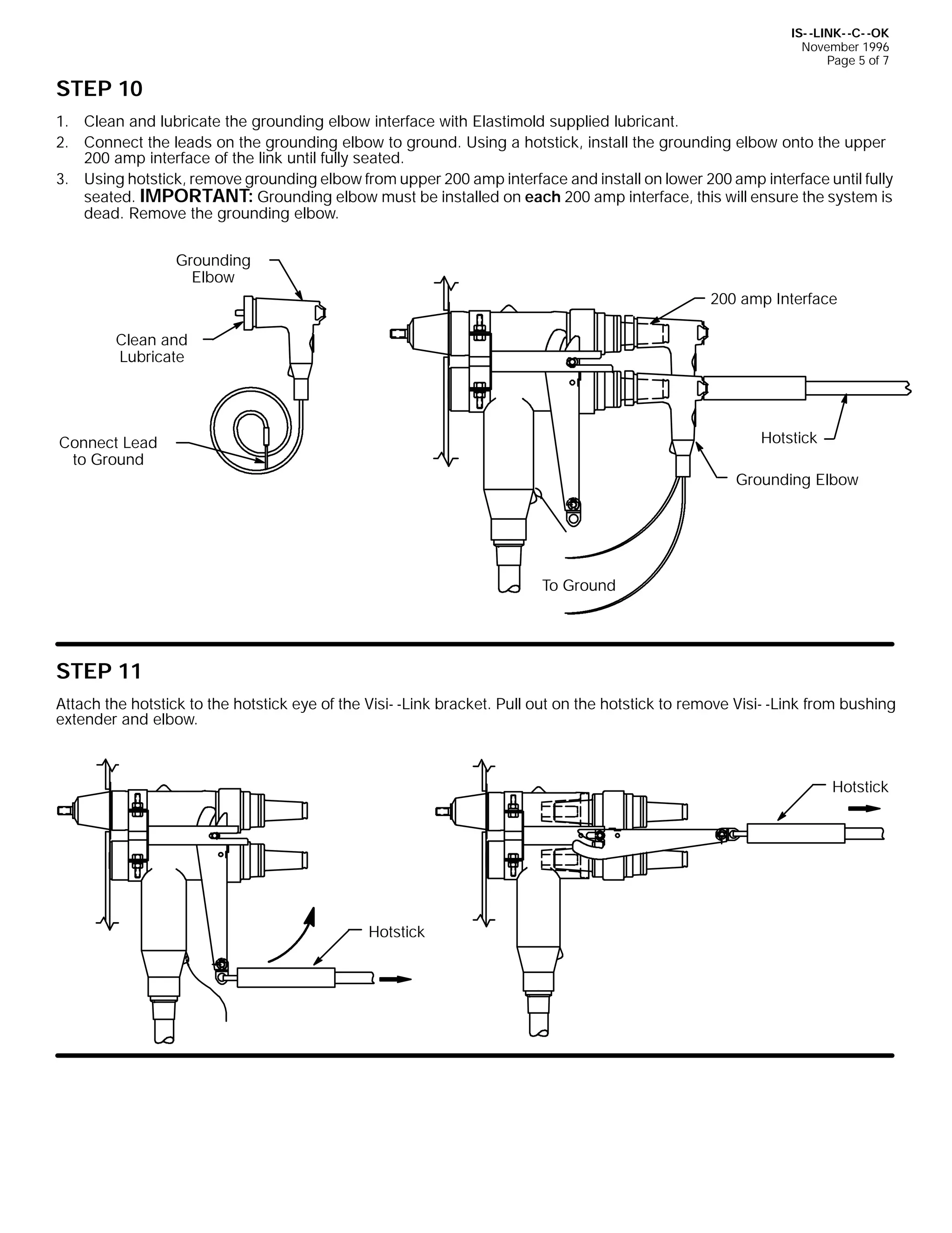
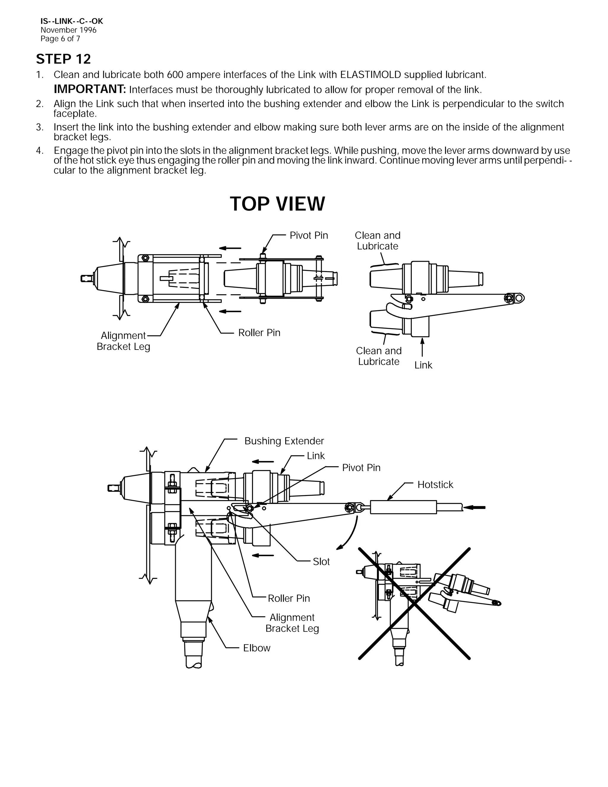
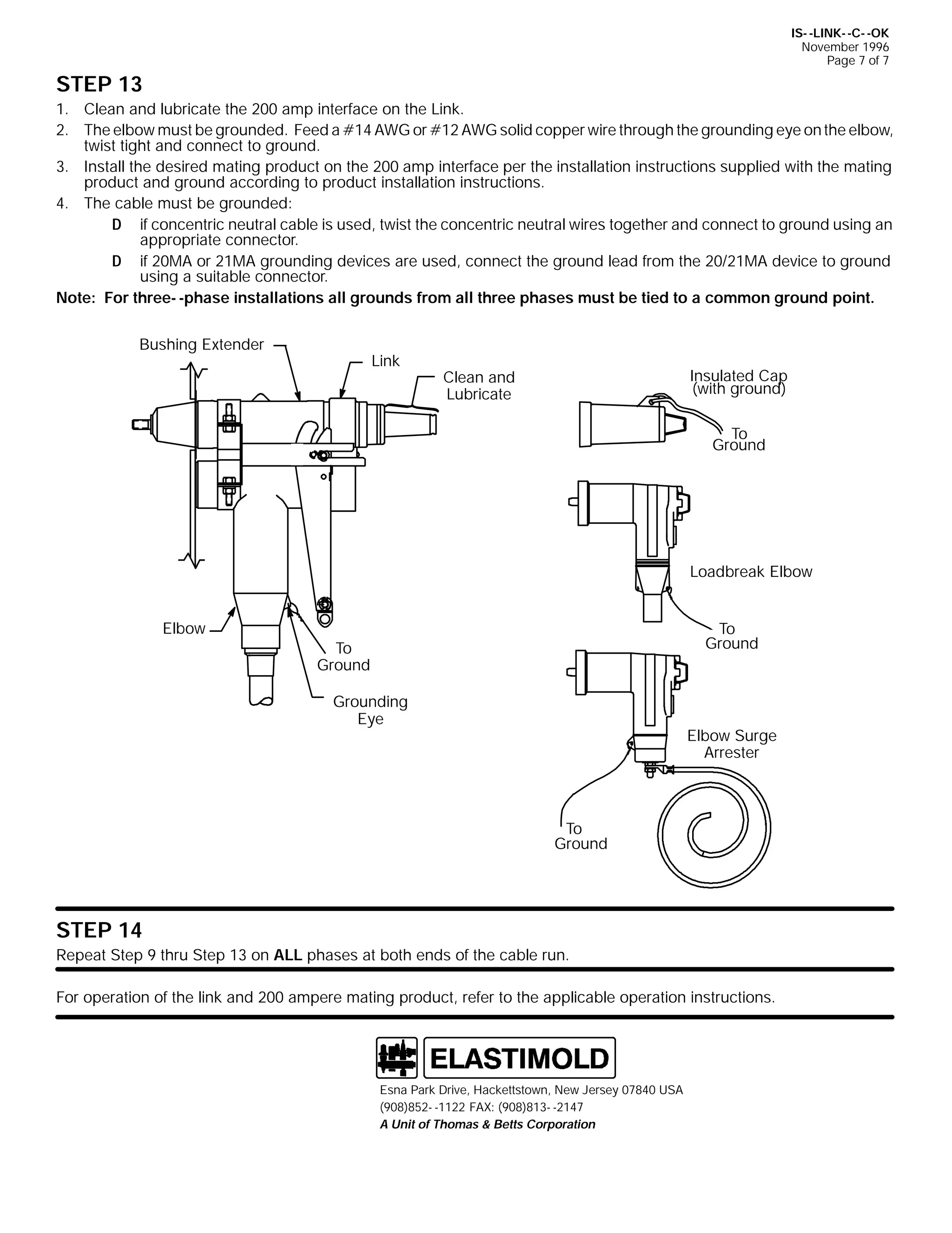

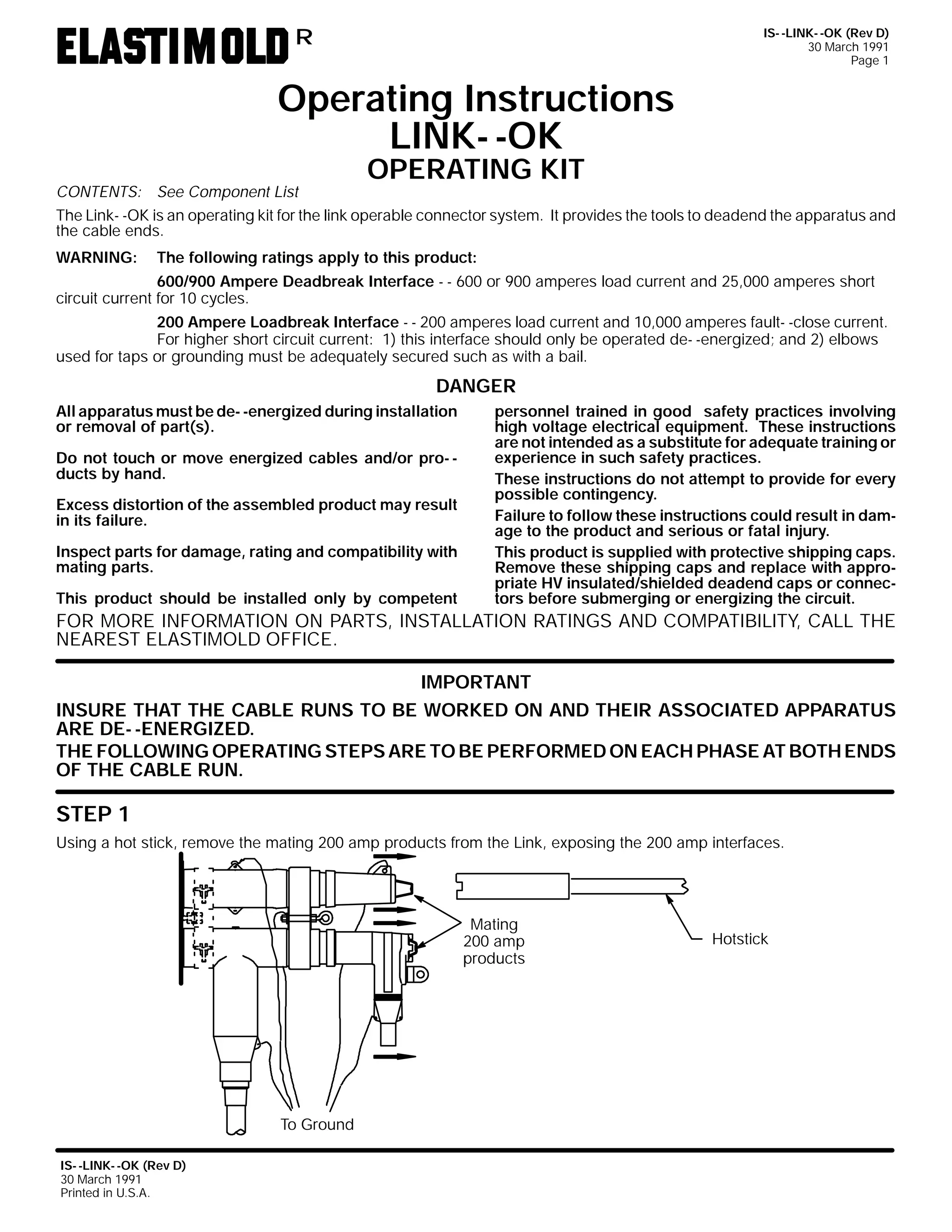
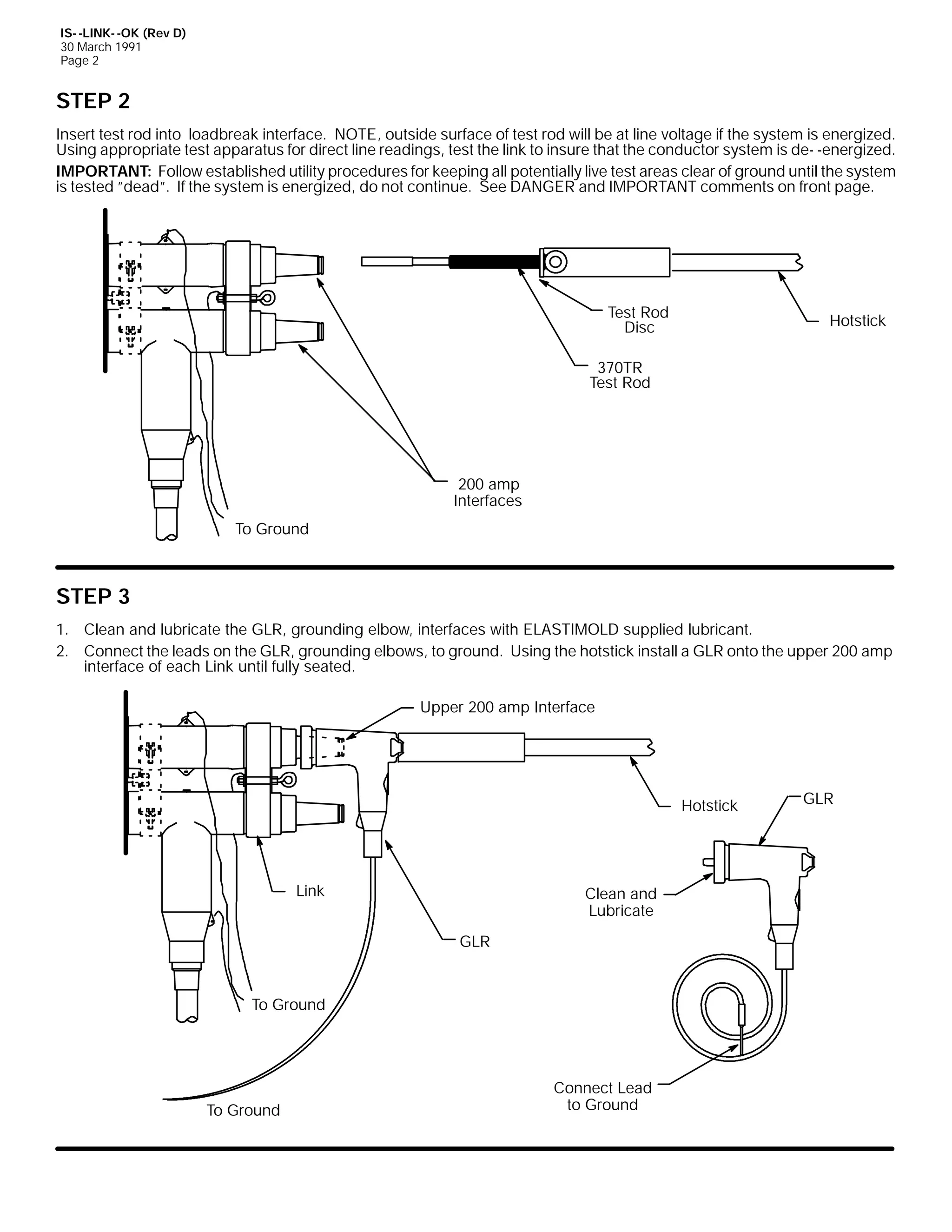
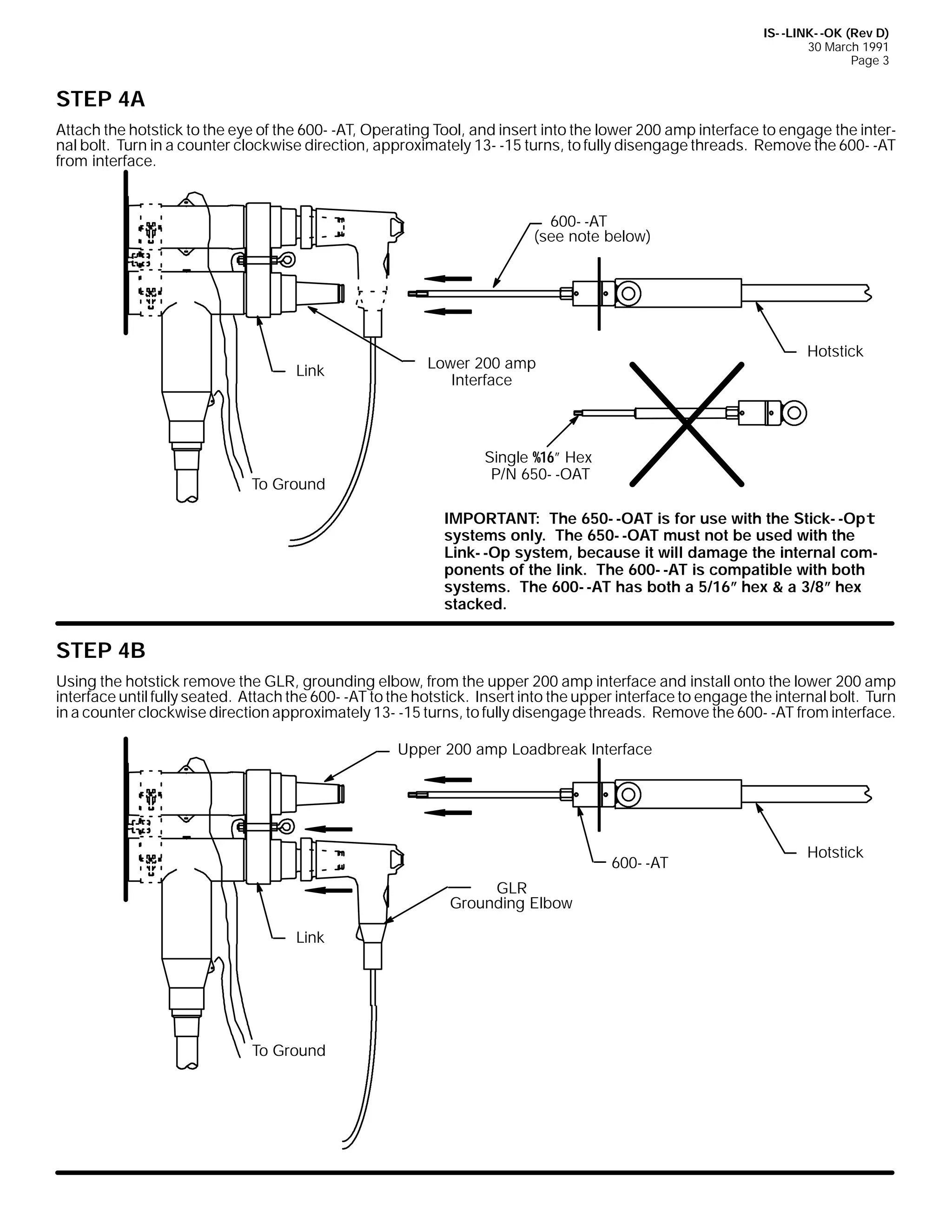
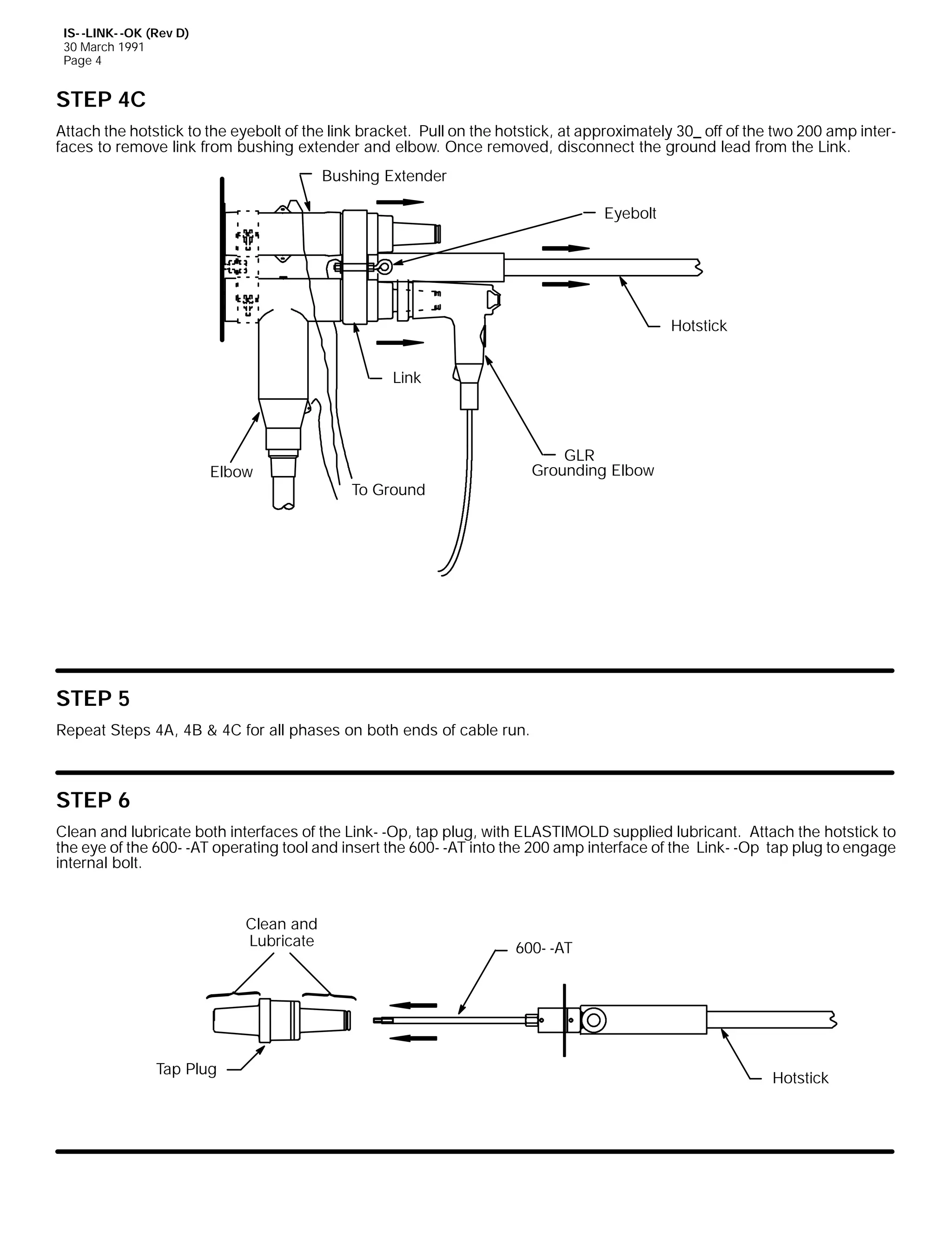
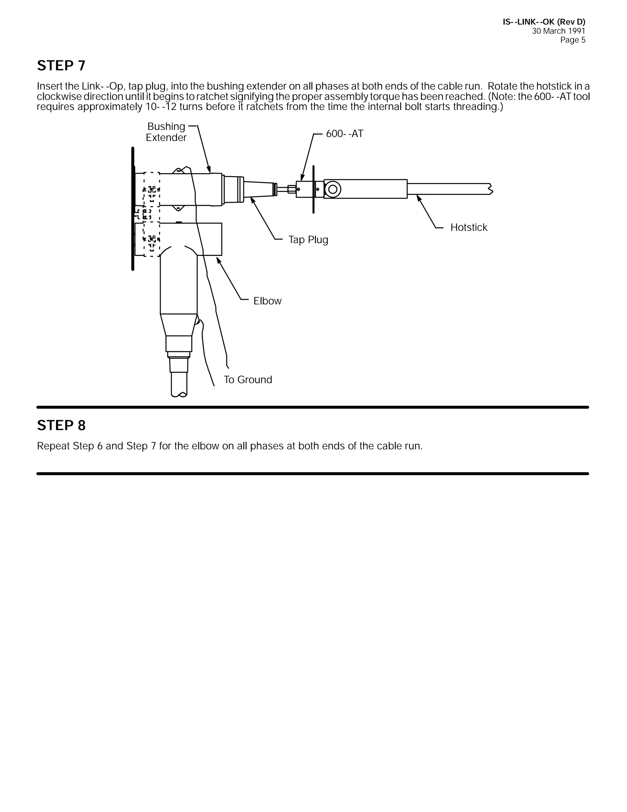
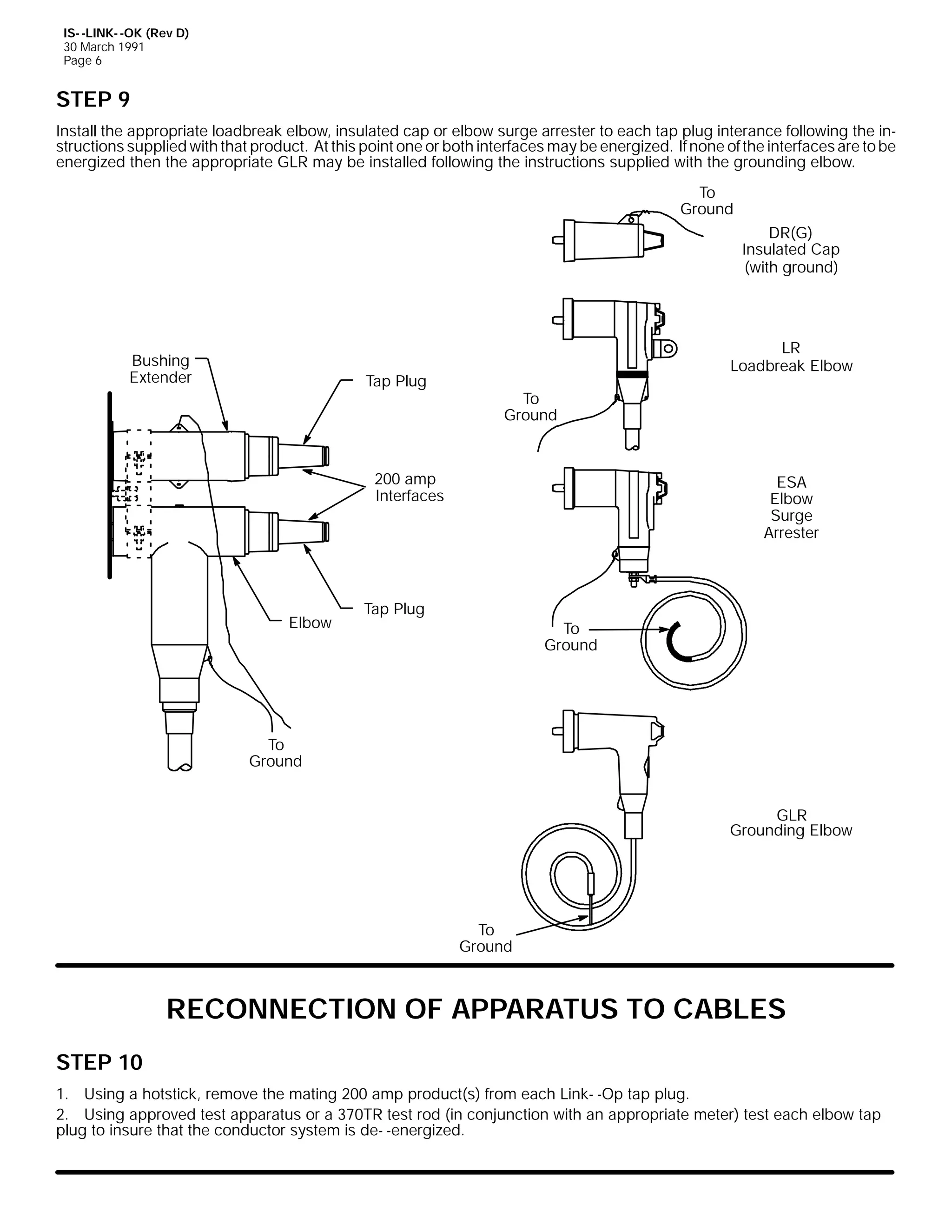
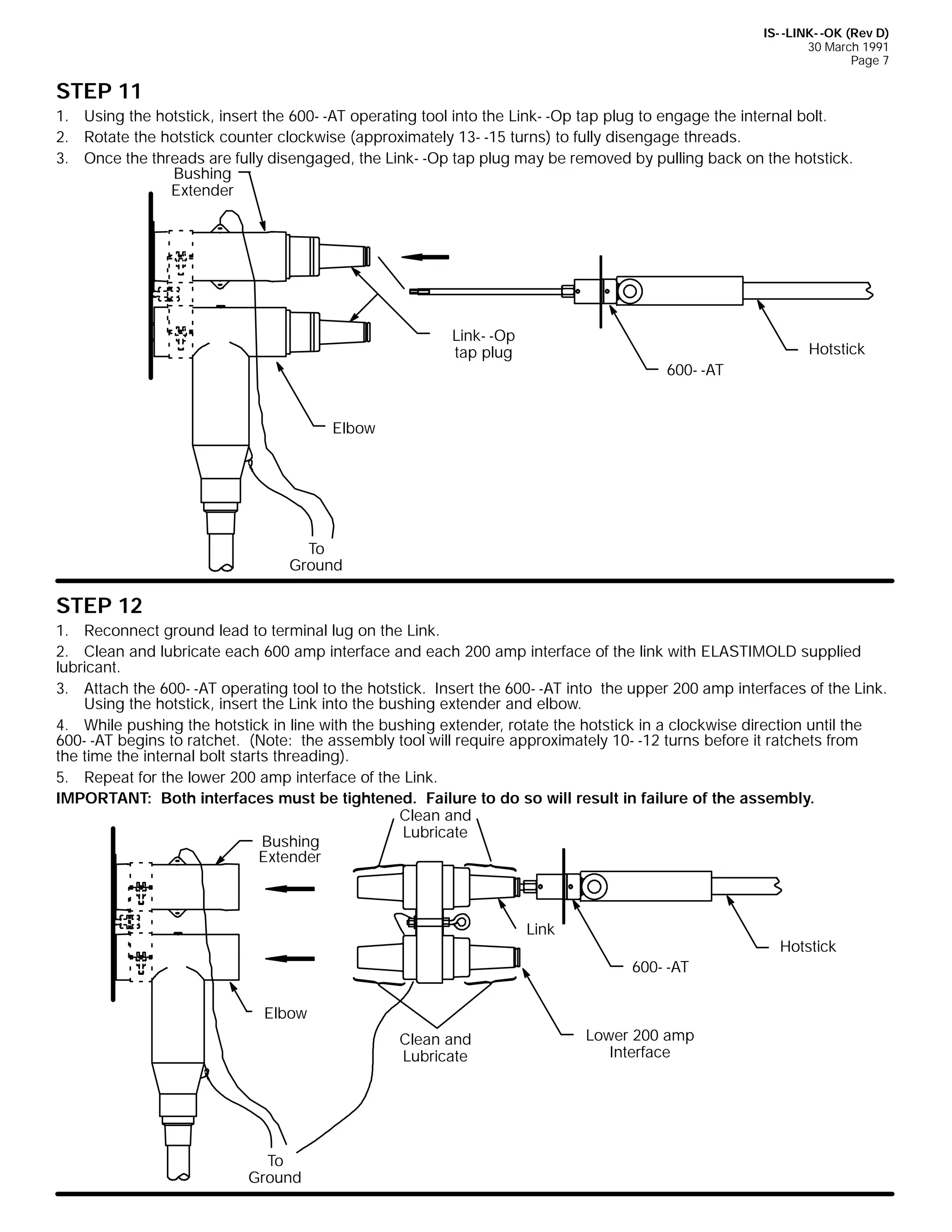
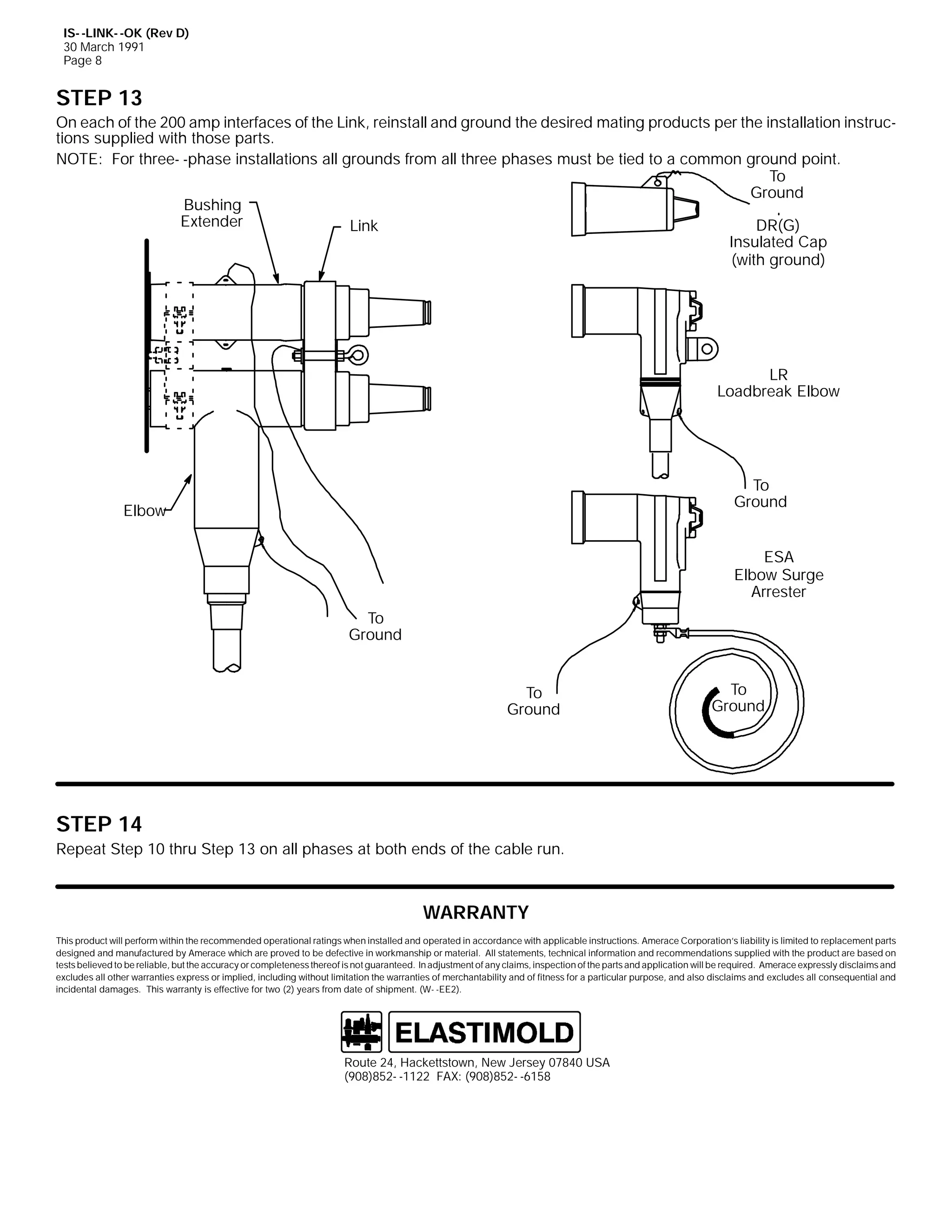
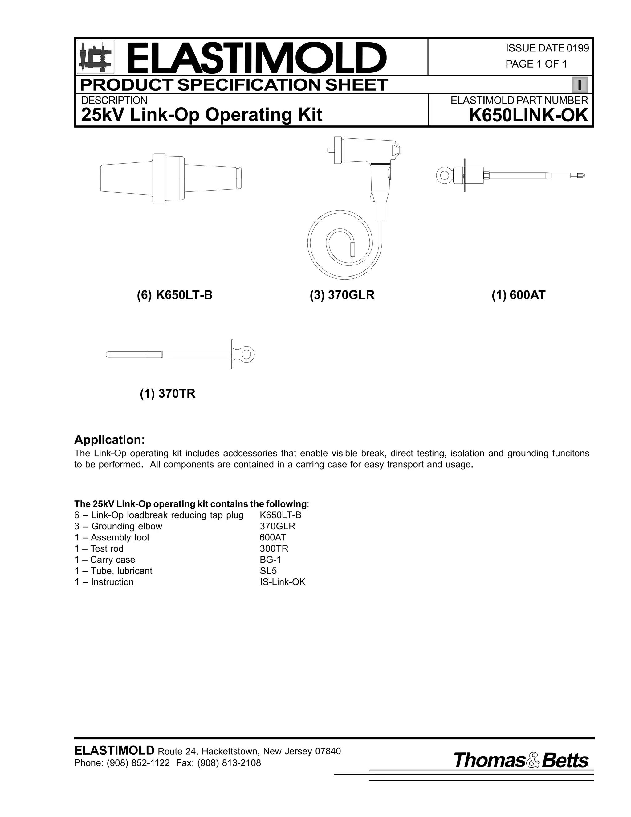

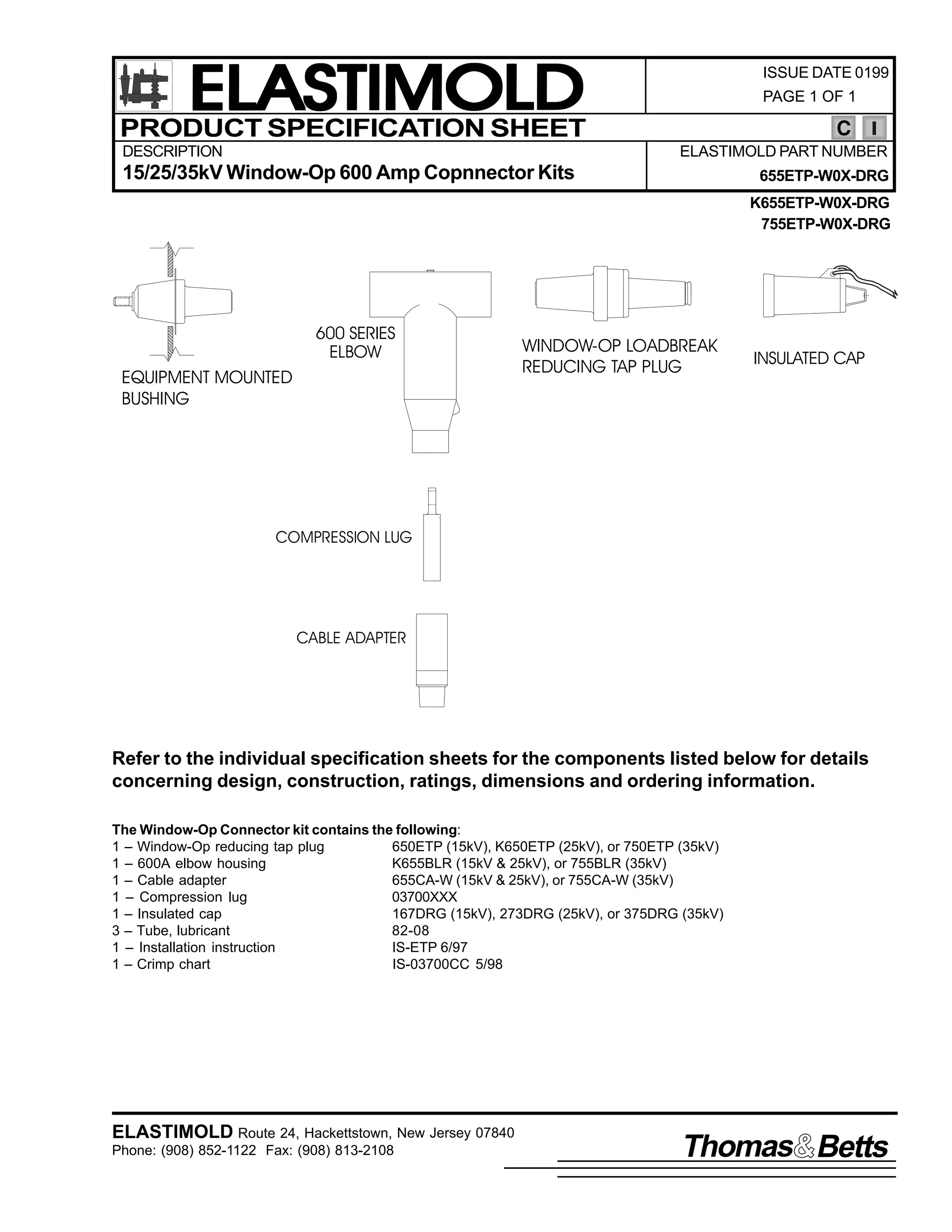
![9
,60 0(73
-XQH 4<<:
3DJH 4 RI 6
,QVWDOODWLRQ ,QVWUXFWLRQV
(73
(OERZ 7DS 3OXJ
&217(176= 7DS 3OXJ/ /XEULFDQW +'2 127 68%67,787(,/ 6WXG +LI DSSOLFDEOH,/ ,QVWDOODWLRQ ,QVWUXFWLRQV1
:$51,1*= 7+(
$9$,/$%/( )$8/7 &855(17 0867 %( /,0,7(' 72 43/333 $03(5(6 :+(1 86,1* 7+,6 352'8&71
7KH (73 LV GHVLJQHG WR SURYLGH D 533 DPSHUH ORDGEUHDN WDS DW VVWHP YROWDJH DV LQGLFDWHG RQ WKH (731
:$51,1*= 7+( )2//2:,1* 5$7,1*6 $33/< 72 7+,6 352'8&7=
9332<33 $PSHUH 'HDGEUHDN ,QWHUIDFH 0 0 933 RU <33 DPSHUHV ORDG FXUUHQW DQG 58/333 DPSHUHV VKRUW FLUFXLW
FXUUHQW IRU 43 FFOHV1
533 $PSHUH /RDGEUHDN ,QWHUIDFH 0 0 533 DPSHUHV ORDG FXUUHQW DQG 43/333 DPSHUHV IDXOW0 0FORVH FXUUHQW1
)RU KLJKHU VKRUW FLUFXLW FXUUHQW= 4, WKLV LQWHUIDFH VKRXOG RQO EH RSHUDWHG
GH0 0HQHUJL]HG> DQG 5, HOERZV XVHG IRU WDSV RU JURXQGLQJ PXVW EH
DGHTXDWHO VHFXUHG VXFK DV ZLWK D EDLO1
'$1*(5
$OO DSSDUDWXV PXVW EH GH0 0HQHUJL]HG GXULQJ LQVWDOODWLRQ
RU UHPRYDO RI SDUW+V,1
'R QRW WRXFK RU PRYH HQHUJL]HG FDEOHV DQG2RU SURGXFWV
E KDQG1
([FHVV GLVWRUWLRQ RI WKH DVVHPEOHG SURGXFW PD UHVXOW
LQ LWV IDLOXUH1
,QVSHFW SDUWV IRU GDPDJH/ UDWLQJ DQG FRPSDWLELOLW ZLWK
PDWLQJ SDUWV1
7KLV SURGXFW VKRXOG EH LQVWDOOHG RQO E FRPSHWHQW
SHUVRQQHO WUDLQHG LQ JRRG VDIHW SUDFWLFHV LQYROYLQJ
KLJK YROWDJH HOHFWULFDO HTXLSPHQW1 7KHVH LQVWUXFWLRQV
DUH QRW LQWHQGHG DV D VXEVWLWXWH IRU DGHTXDWH WUDLQLQJ RU
H[SHULHQFH LQ VXFK VDIHW SUDFWLFHV1
7KHVH LQVWUXFWLRQV GR QRW DWWHPSW WR SURYLGH IRU HYHU
SRVVLEOH FRQWLQJHQF1
)DLOXUH WR IROORZ WKHVH LQVWUXFWLRQV ZLOO UHVXOW LQ GDPDJH
WR WKH SURGXFW DQG VHULRXV RU IDWDO LQMXU1
)25 025( ,1)250$7,21 21 3$576/ ,167$//$7,21 5$7,1*6 $1' &203$7,%,/,7</ &$// 7+( 1($5(67 (/$67,02/' 2)),&(1
,03257$17
41 &KHFN FRQWHQWV RI SDFNDJH WR LQVXUH LW LV FRPSOHWH
DQG XQGDPDJHG1
51 &KHFN DOO FRPSRQHQWV WR LQVXUH SURSHU ILW ZLWK FDEOH
DQG2RU PDWLQJ SURGXFWV1
61 5HDG HQWLUH LQVWDOODWLRQ LQVWUXFWLRQV EHIRUH VWDUWLQJ1
71 +DYH DOO UHTXLUHG WRROV DW KDQG DQG REVHUYH FOHDQOLQHVV
WKURXJKRXW WKH SURFHGXUH1
67(3 4
3UHSDUH FDEOH XVLQJ VSDGH FRQWDFW DQG LQVWDOO HOERZ DV GHVFULEHG LQ WKH +.,983/5 RU :83/5 LQVWDOODWLRQ LQVWUXFWLRQV1 %HIRUH
PDNLQJ ILUVW FULPS RQ VSDGH FRQWDFW/ DOLJQ LW RQ WKH FDEOH VR WKDW WKH VSDGH OLHV IODW RQ WKH DSSDUDWXV EXVKLQJ FRQWDFW1
&255(&7 326,7,21
$SSDUDWXV
%XVKLQJ
:521* 326,7,21
6SDGH
&RQWDFW
&DEOH
,60 0(73
-XQH 4<<:
3ULQWHG LQ 8161$1
(VQD 3DUN 'ULYH/ +DFNHWWVWRZQ/ 1HZ -HUVH 3:;73 86$
+<3;,;850 04455 )$;= +<3;,;460 0547:
$ 8QLW RI 7KRPDV ) %HWWV &RUSRUDWLRQ](https://image.slidesharecdn.com/elastimold-140130102426-phpapp02/75/Elastimold-Connectors-Loadbreak-Deadbreak-Elbow-Bolted-Tee-Connectors-HV-MV-700-Series-466-2048.jpg)
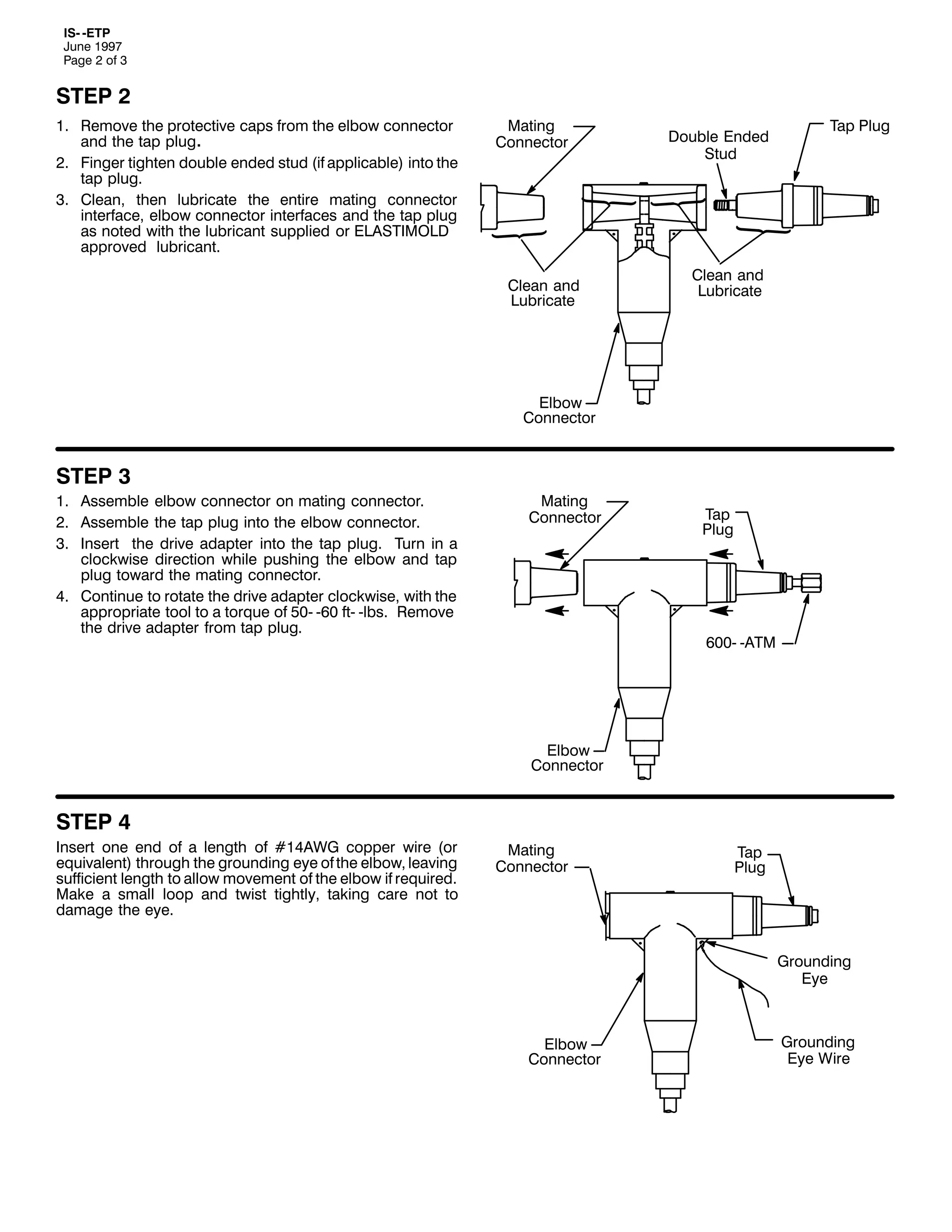
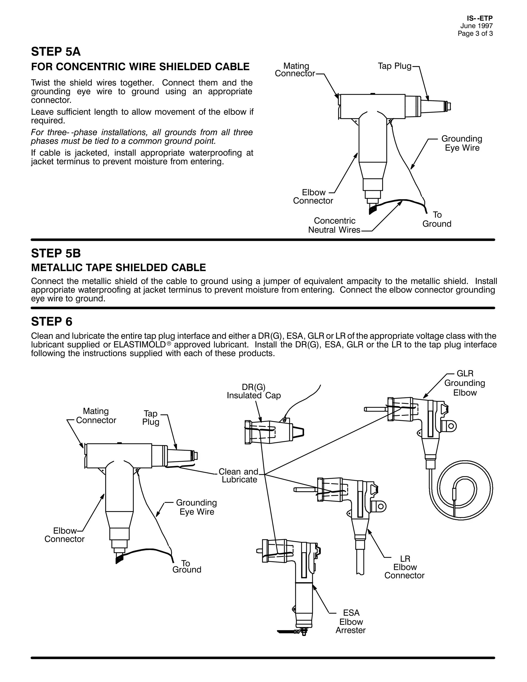
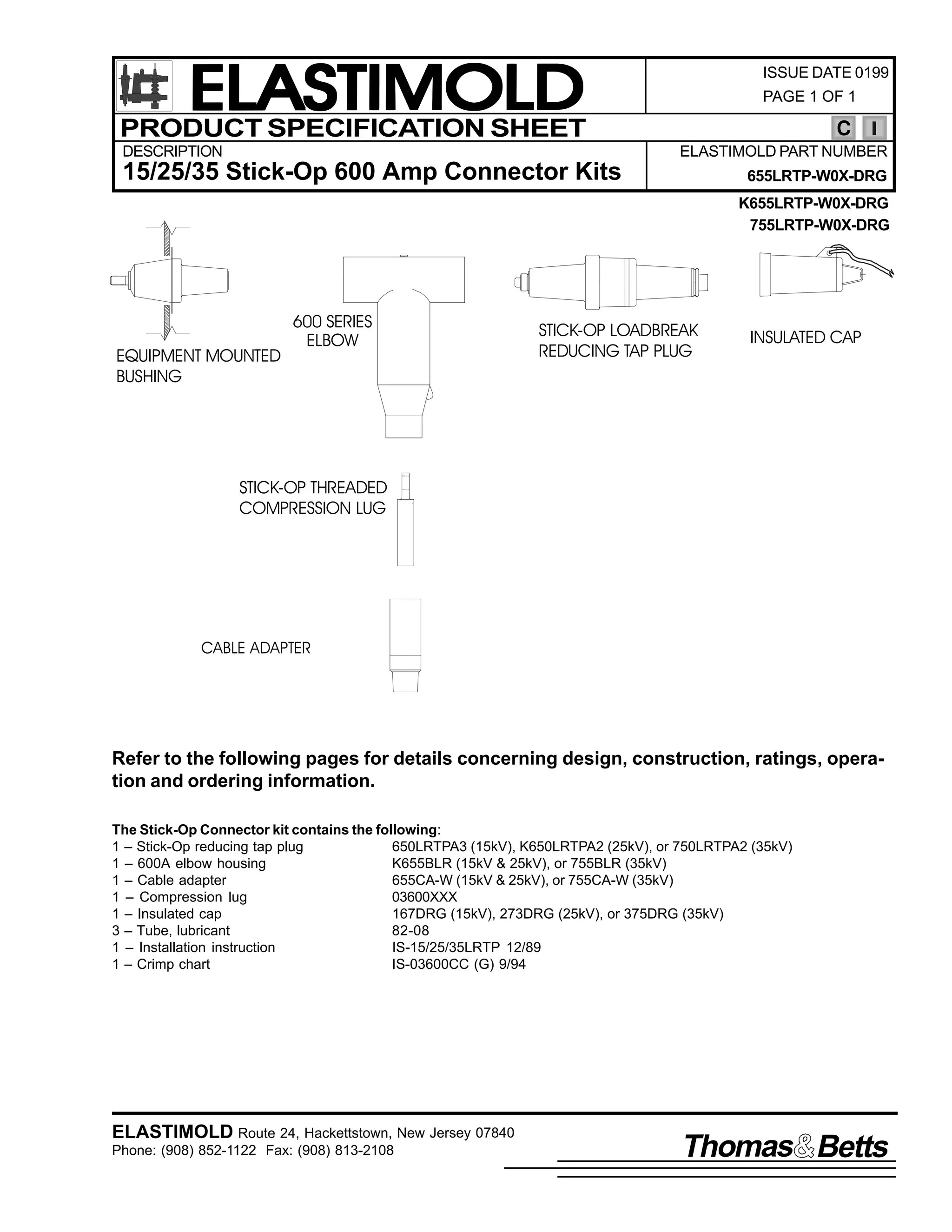
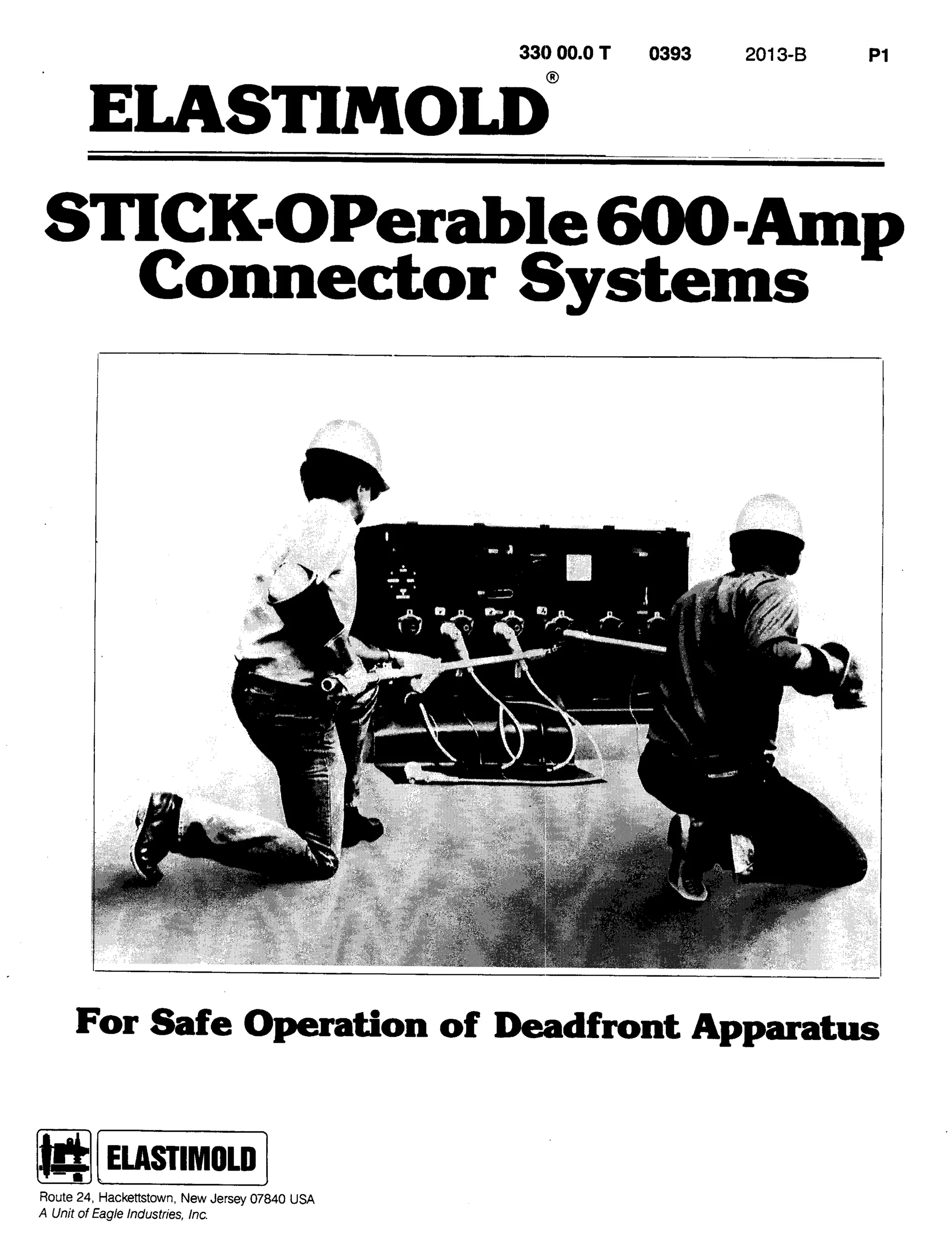
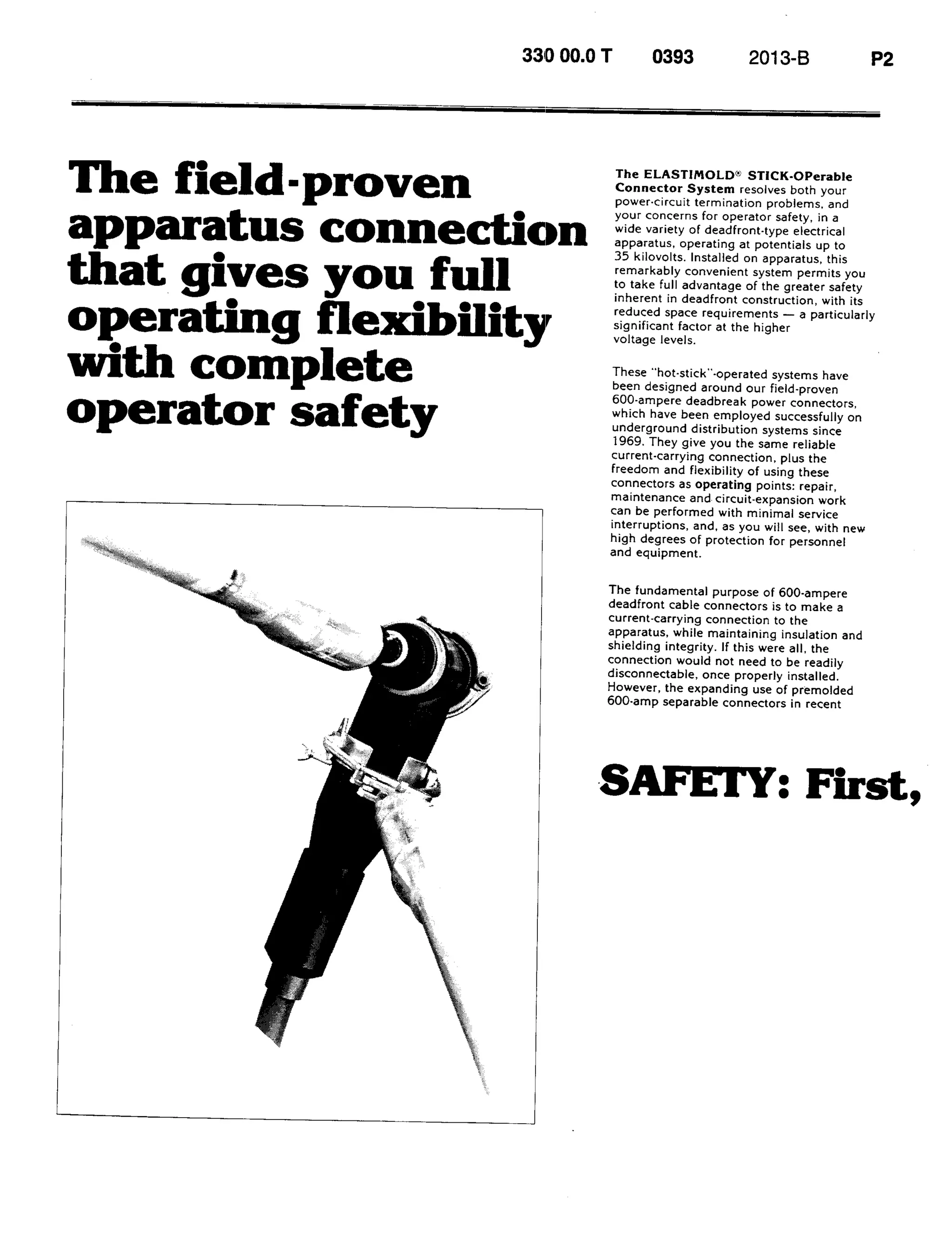
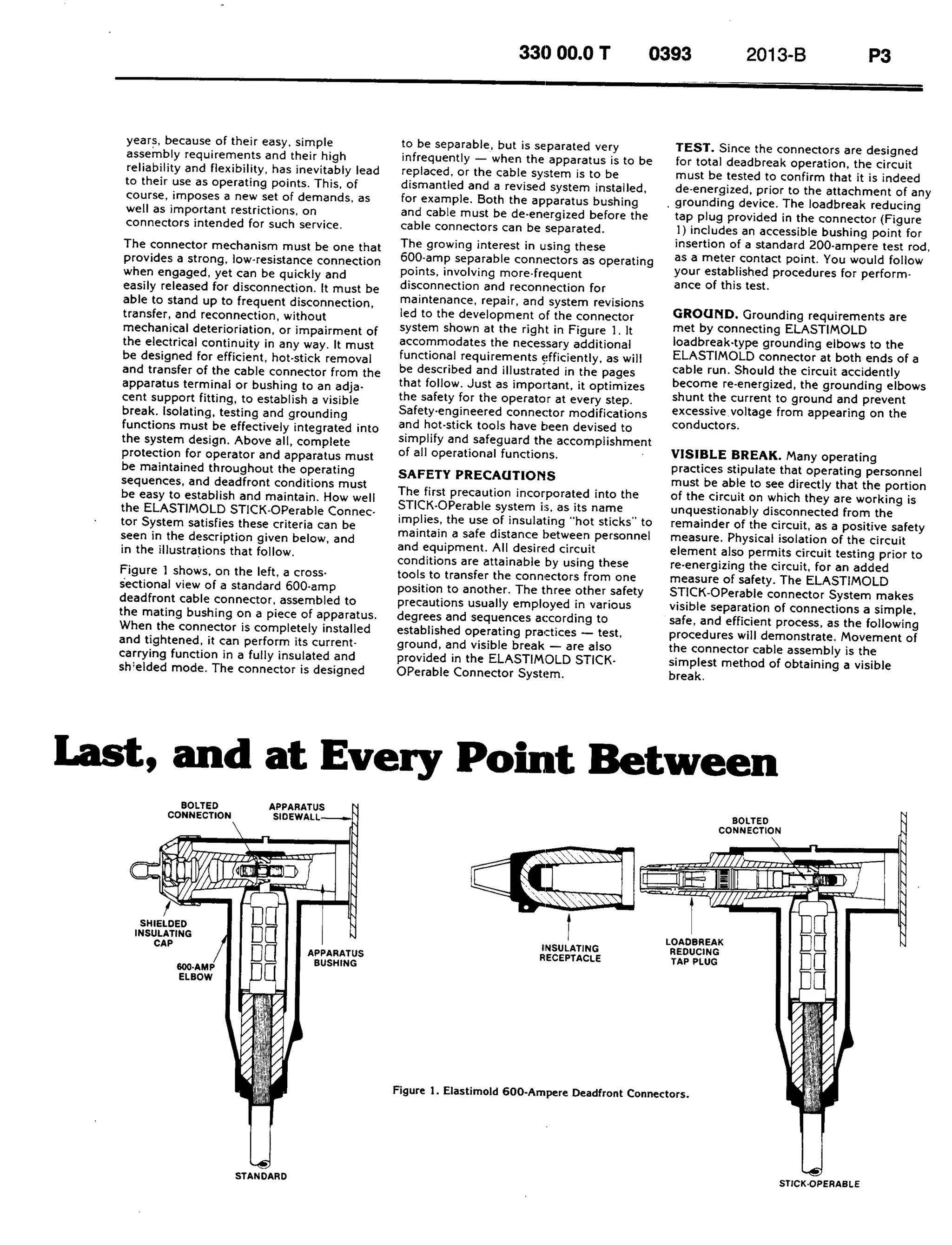
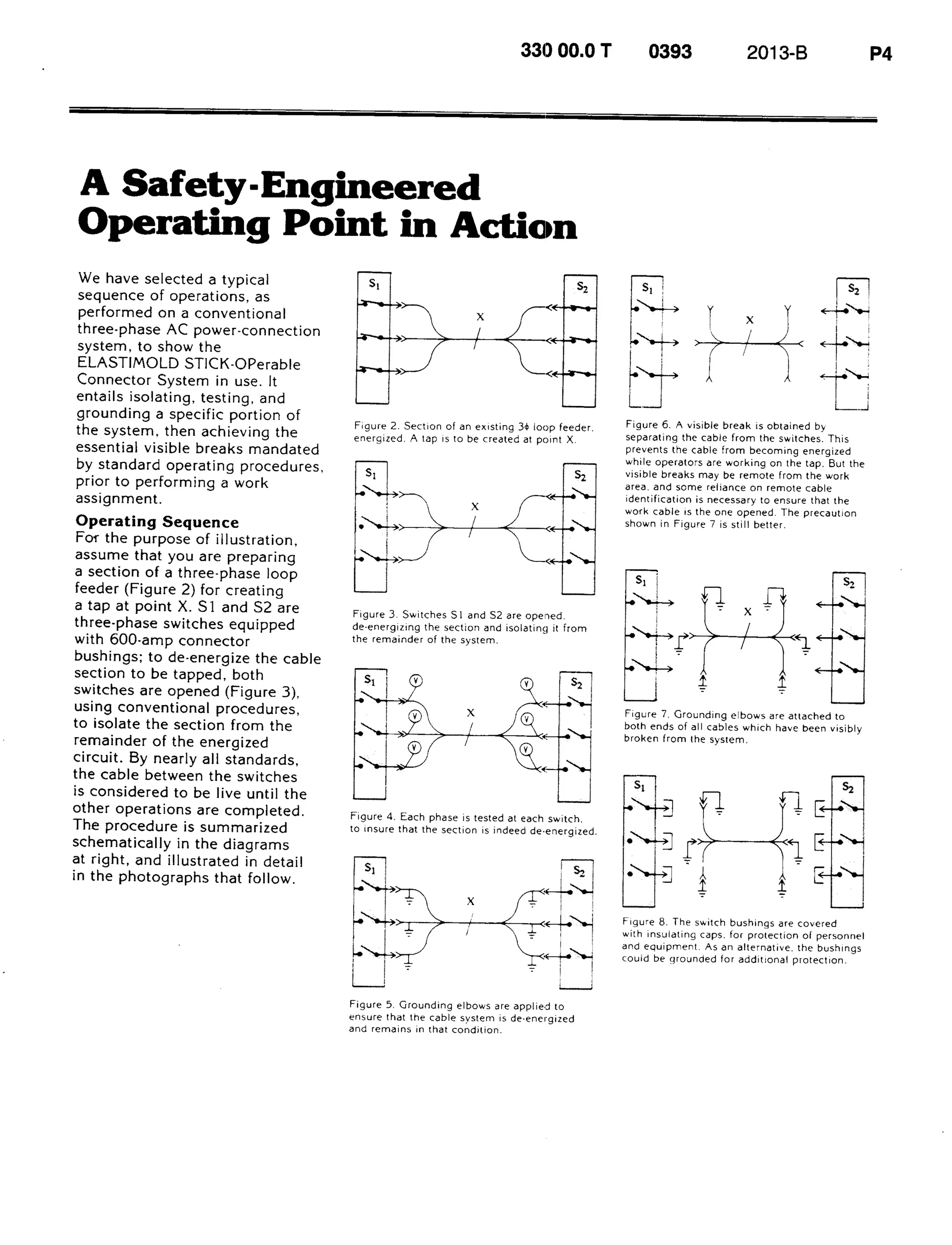
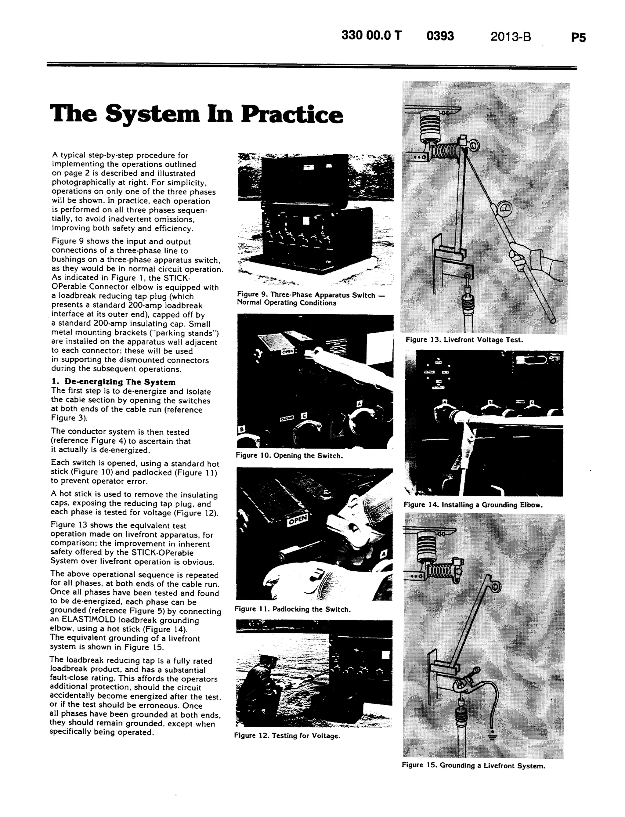
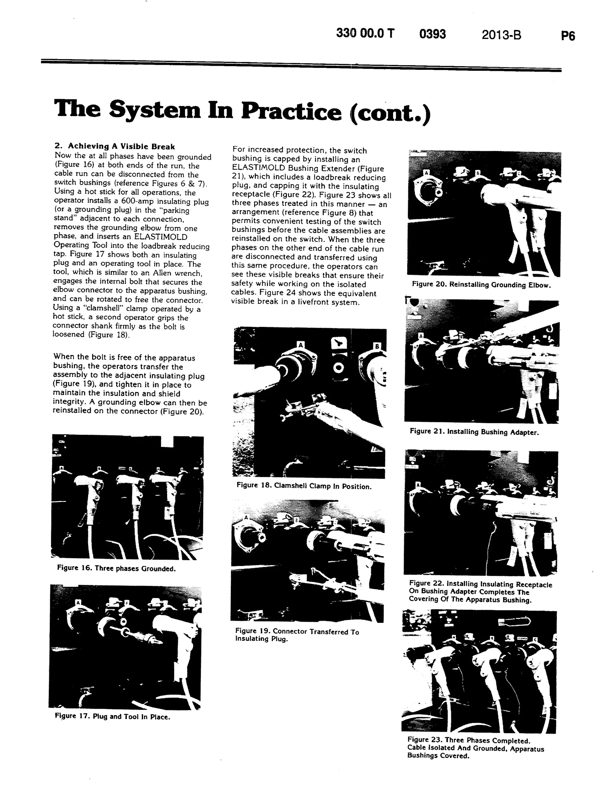
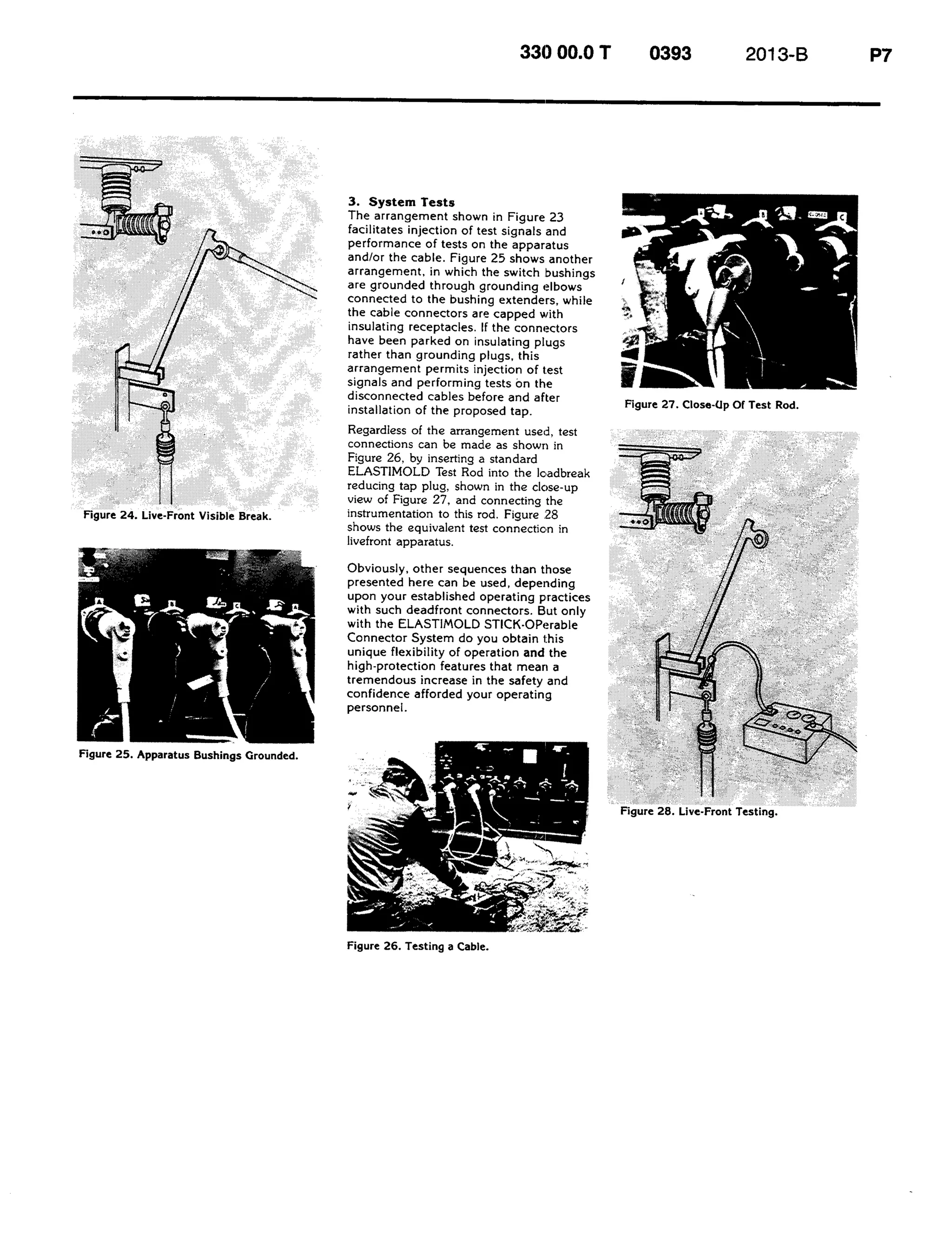
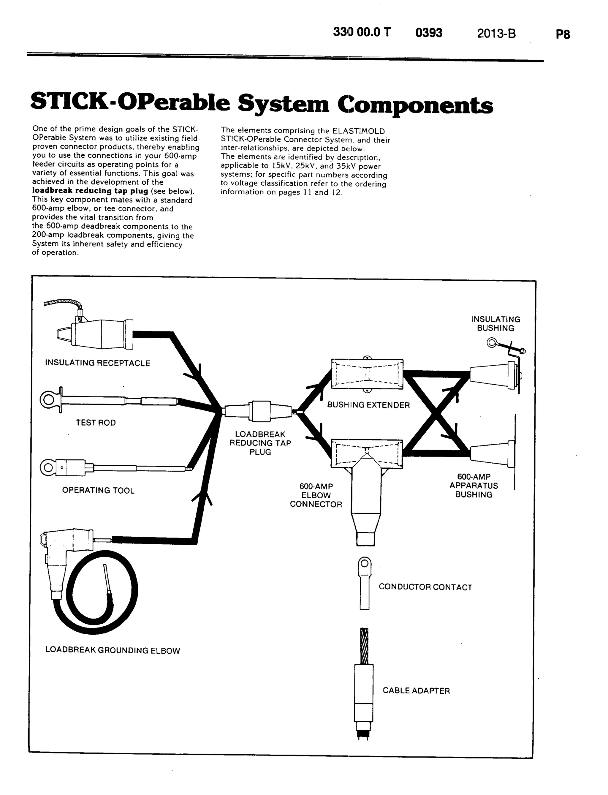
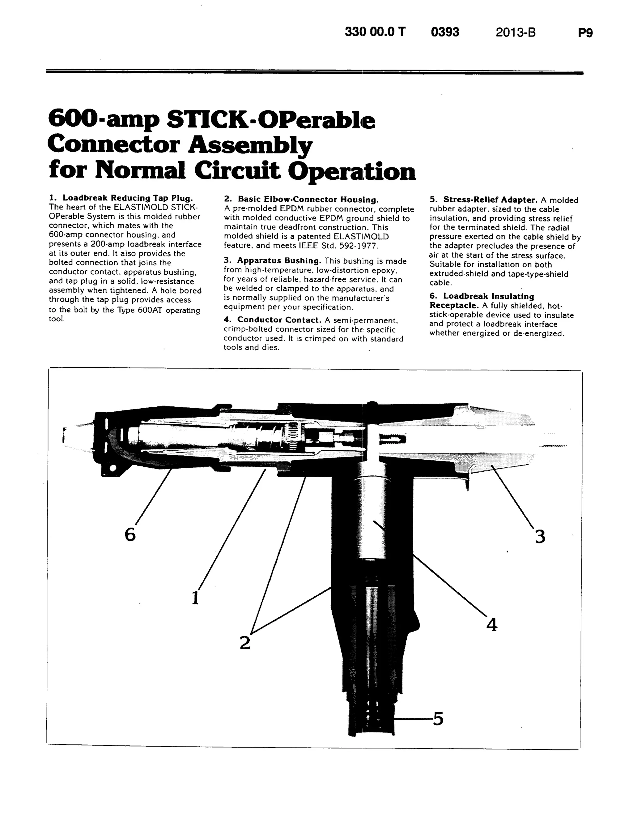
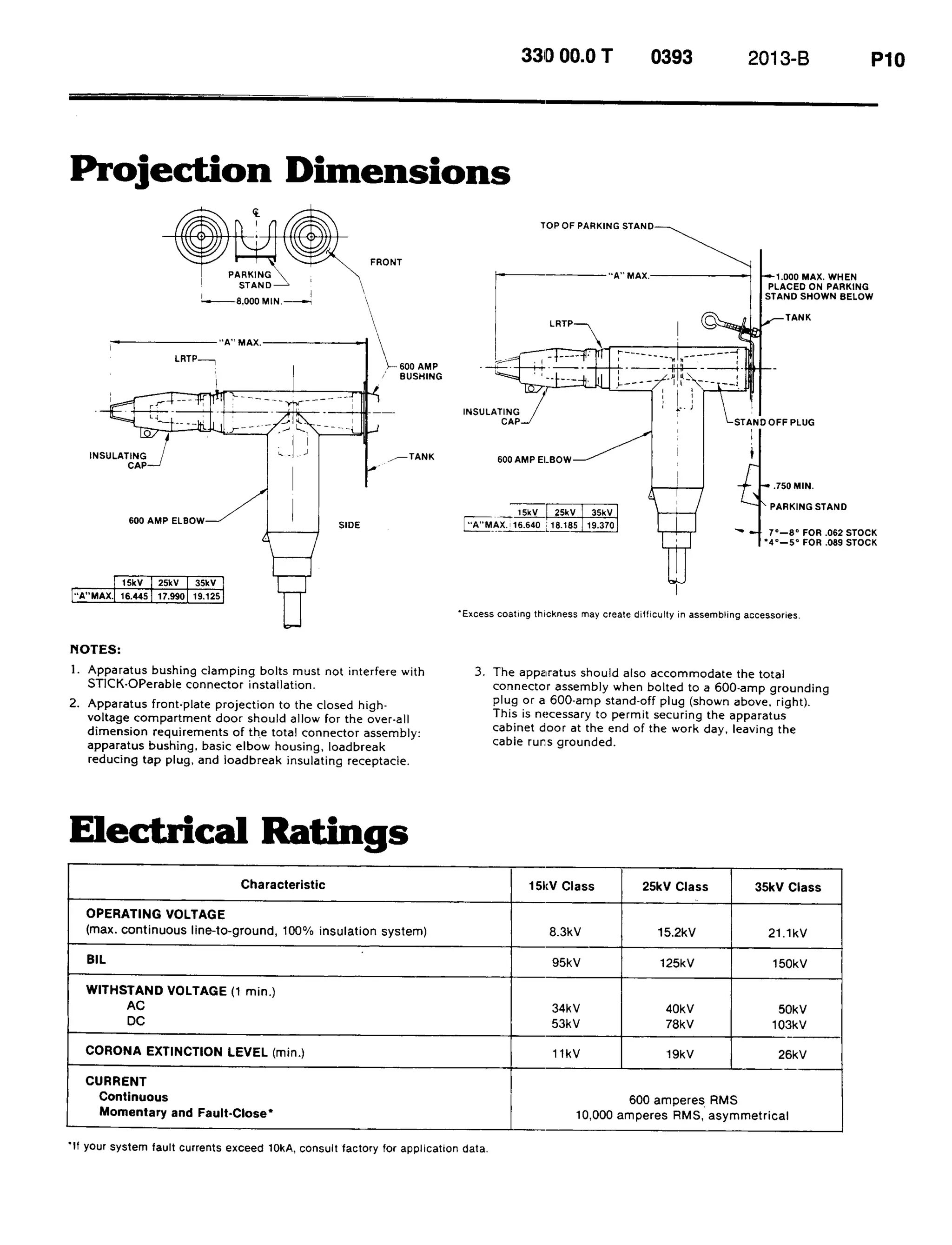
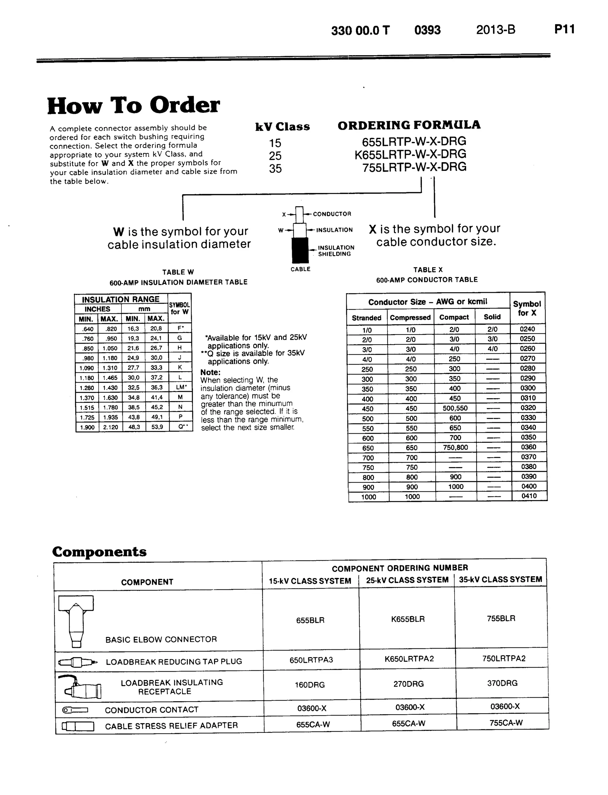
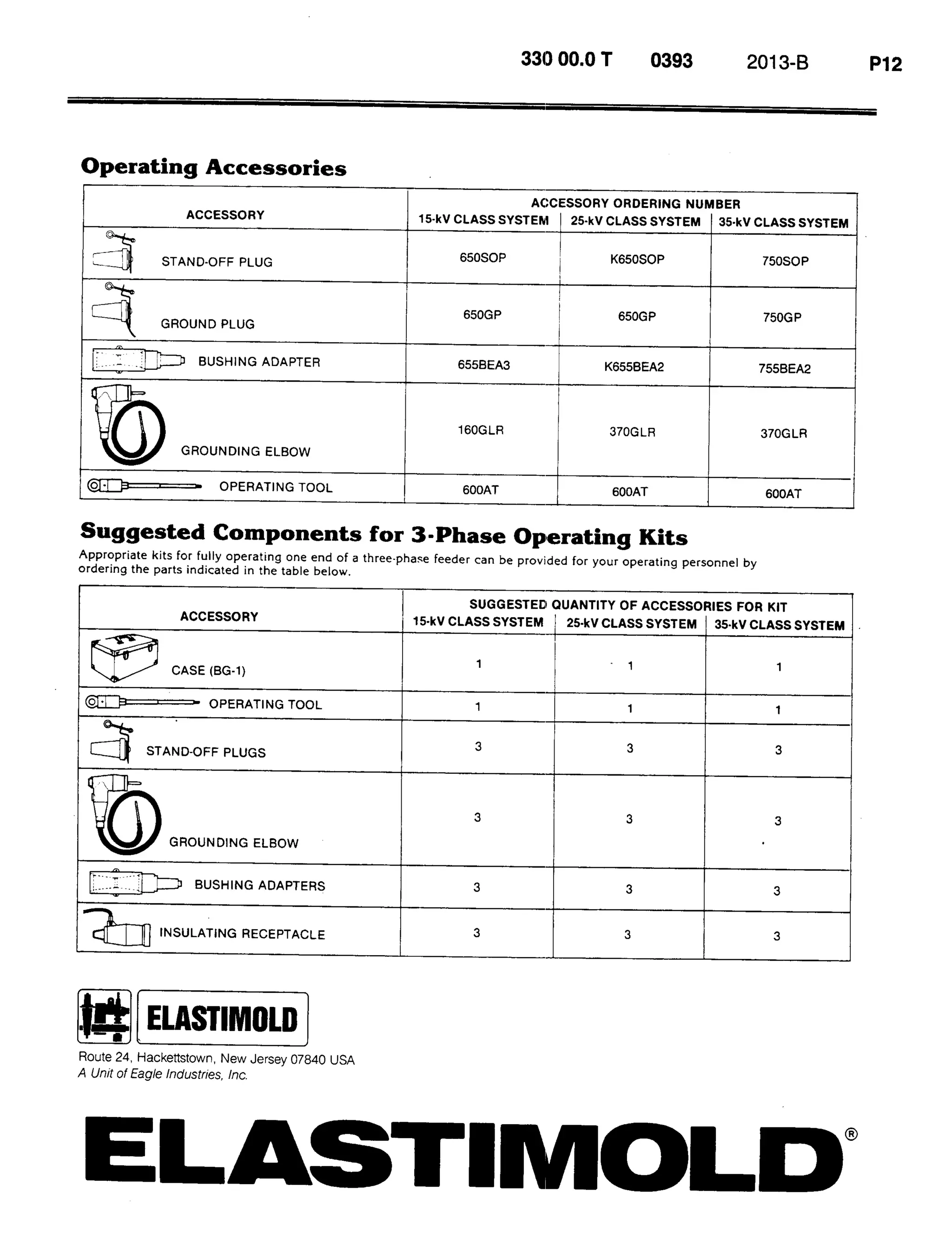


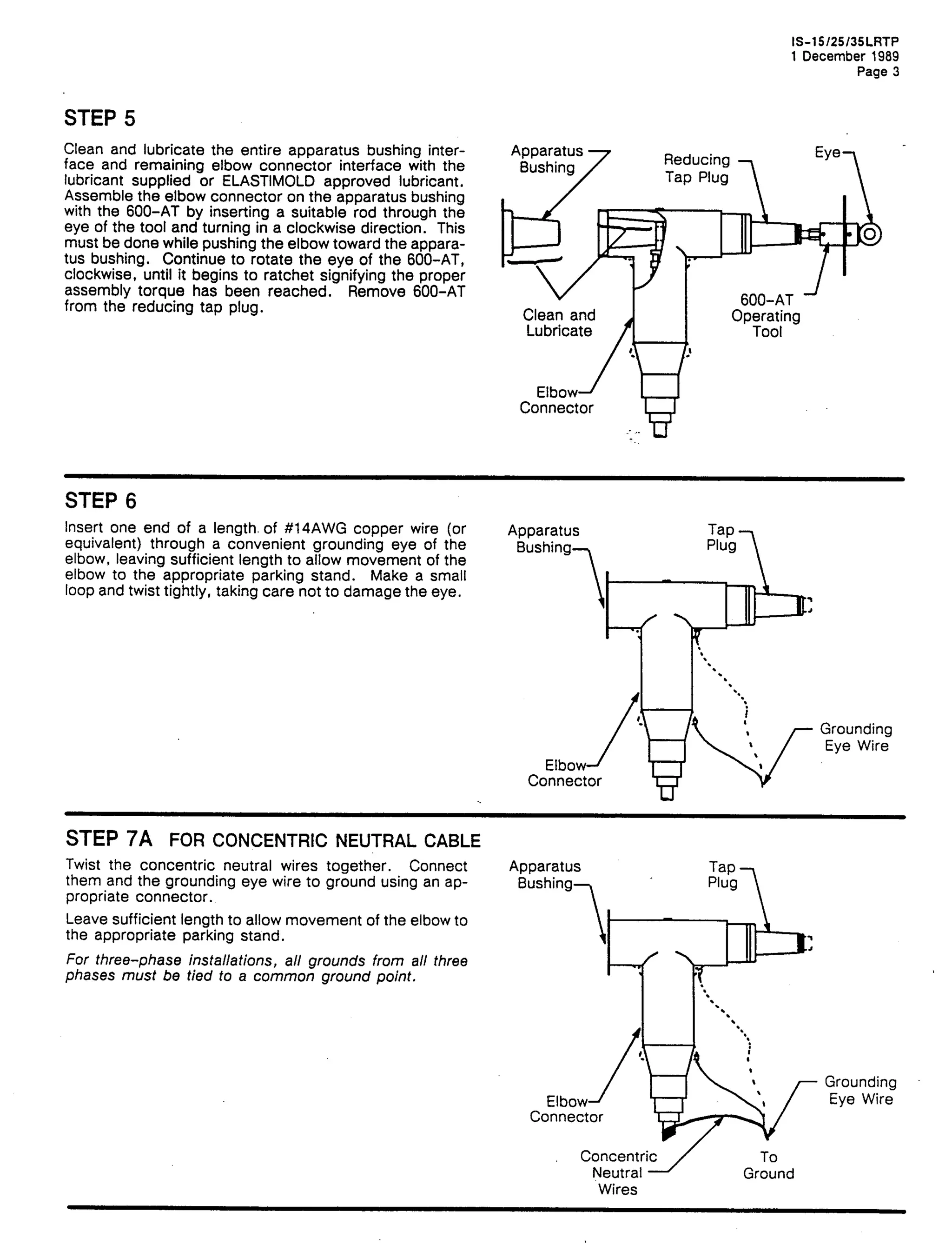

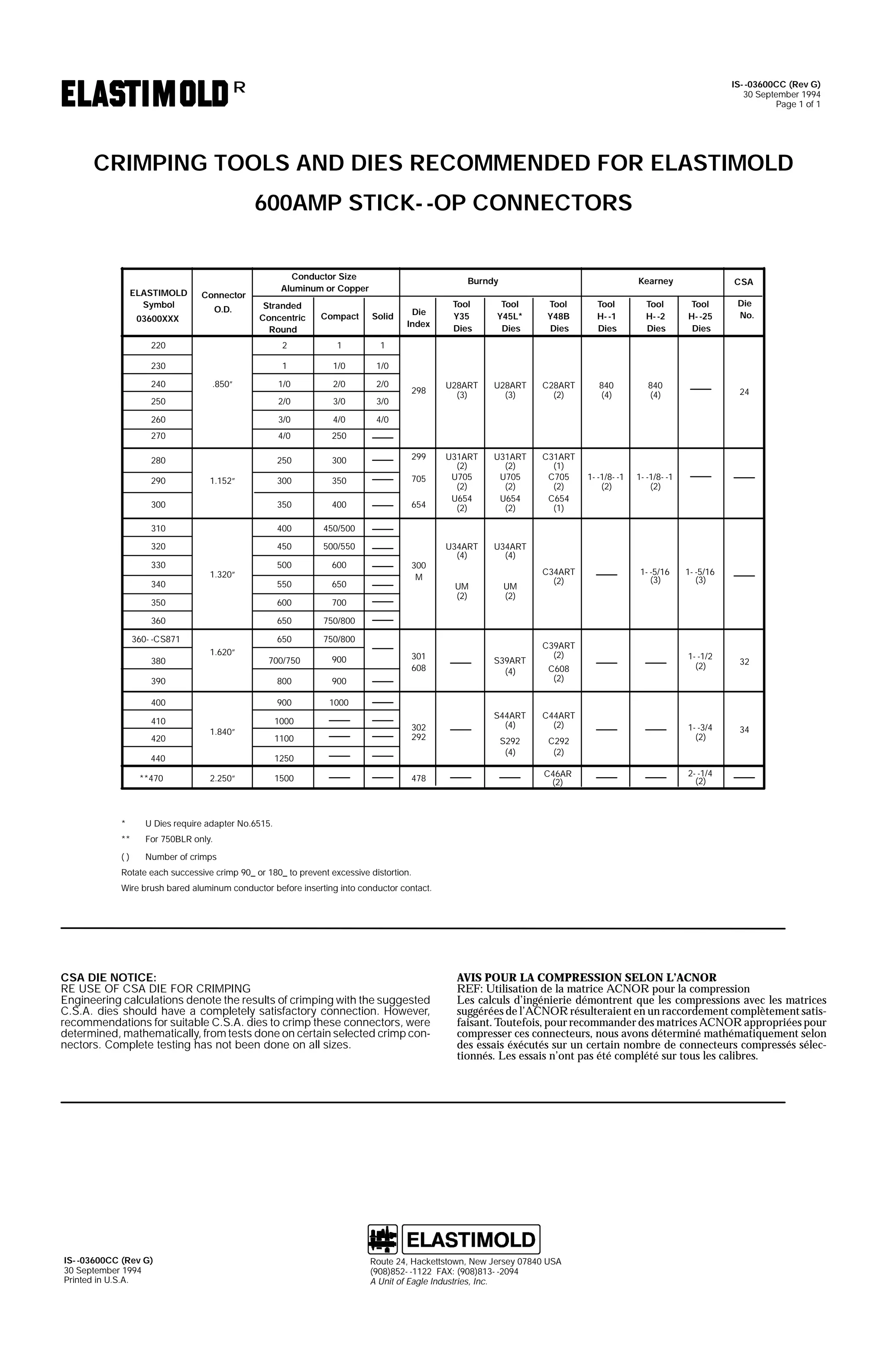
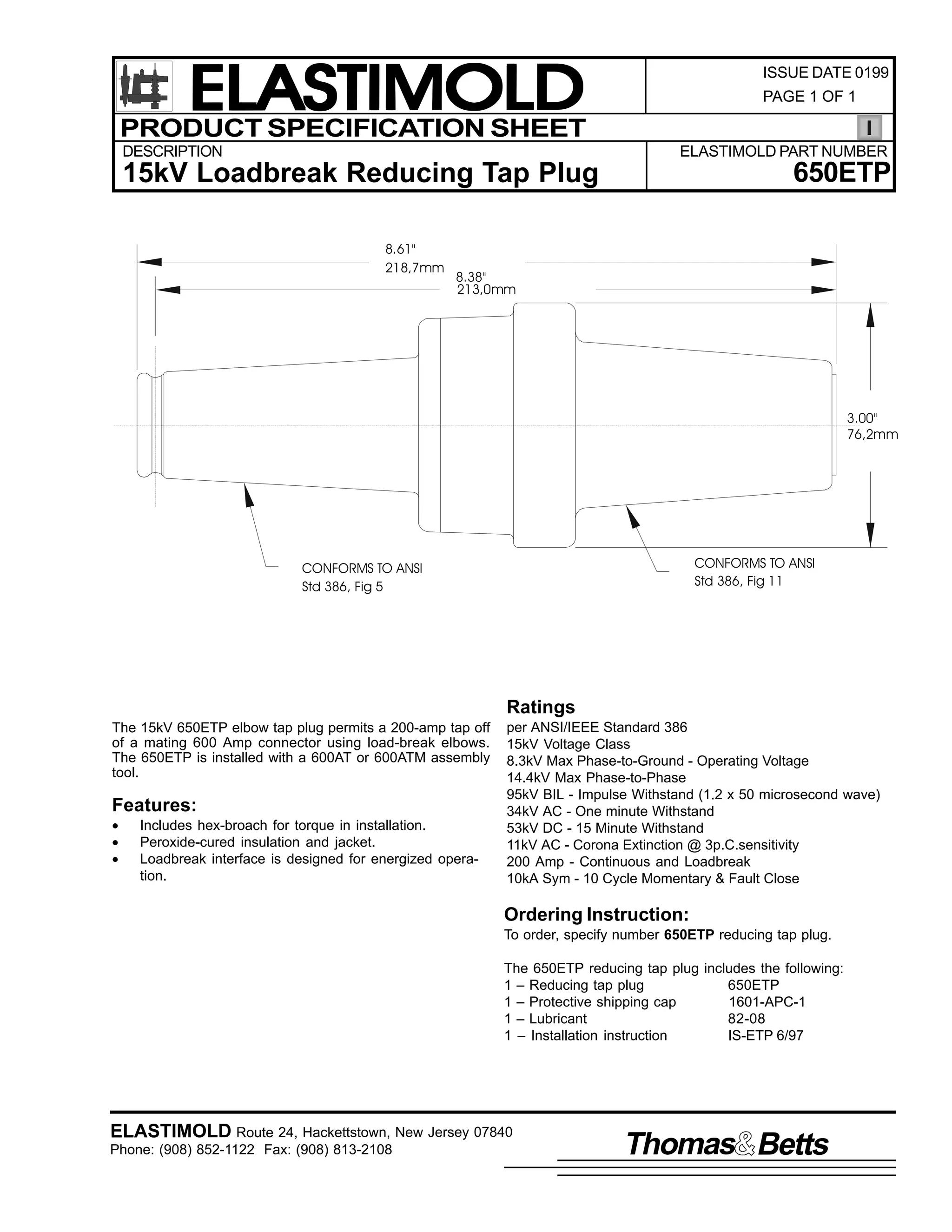
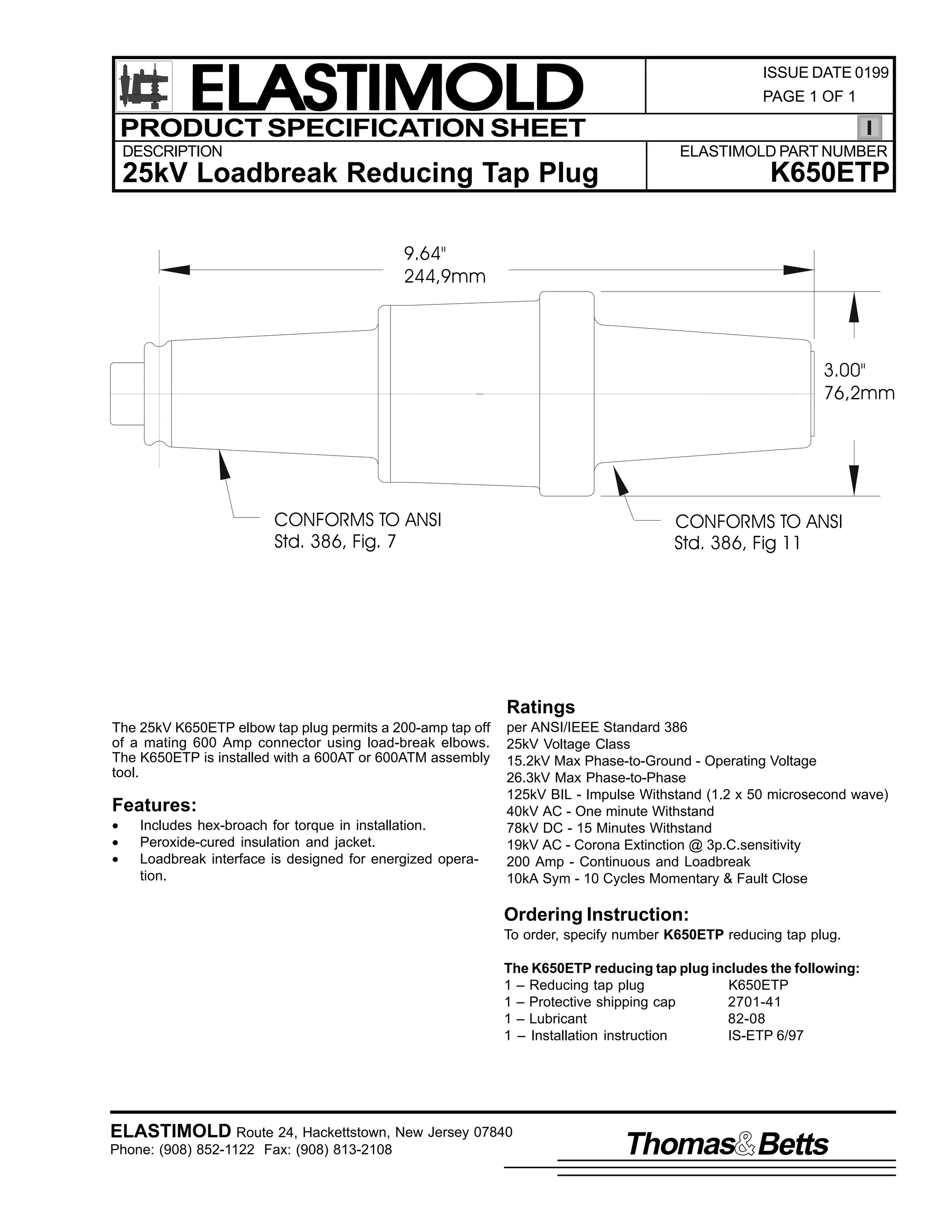

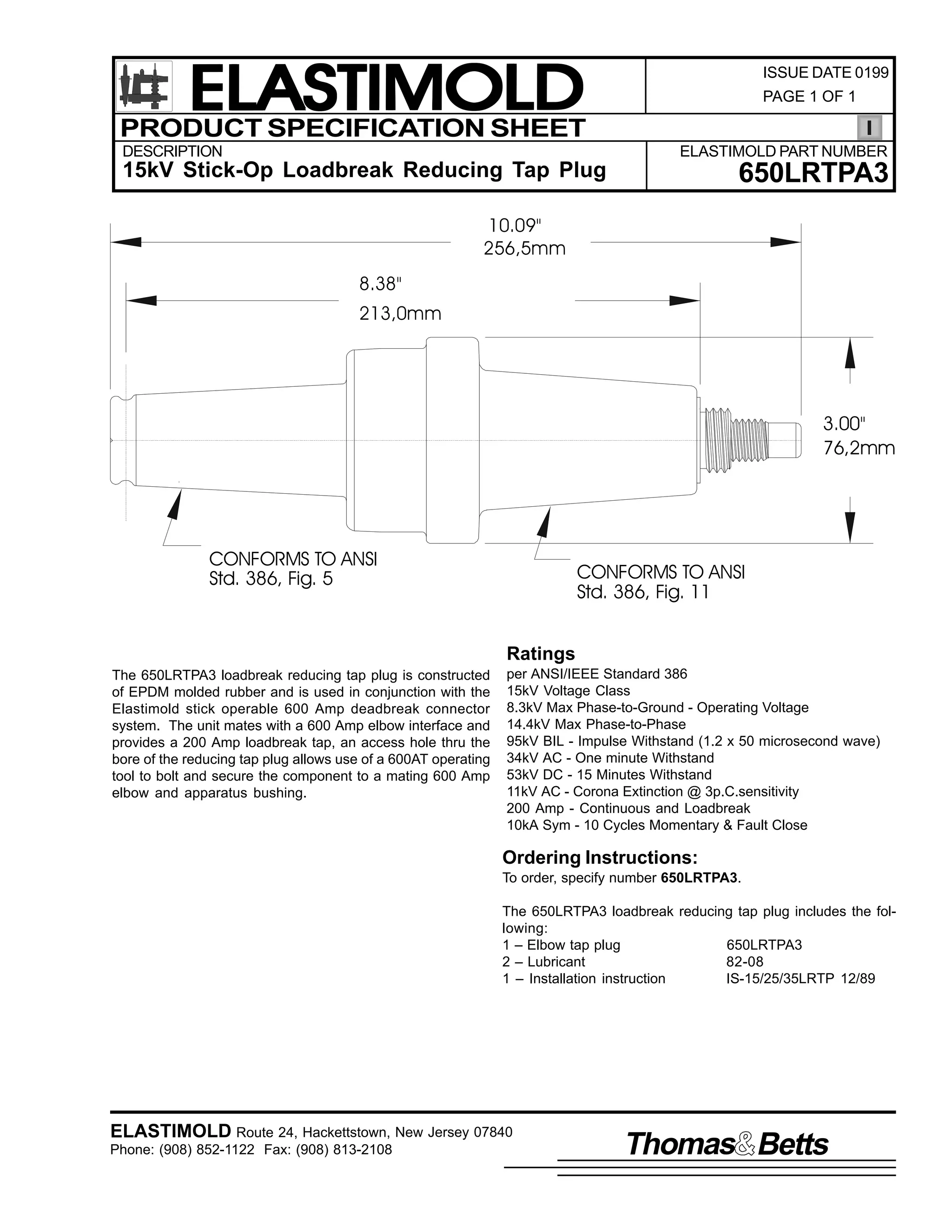
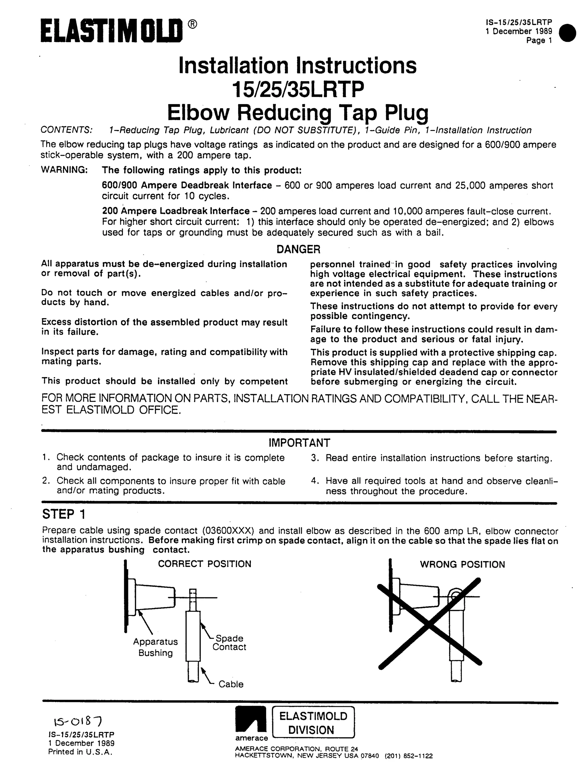
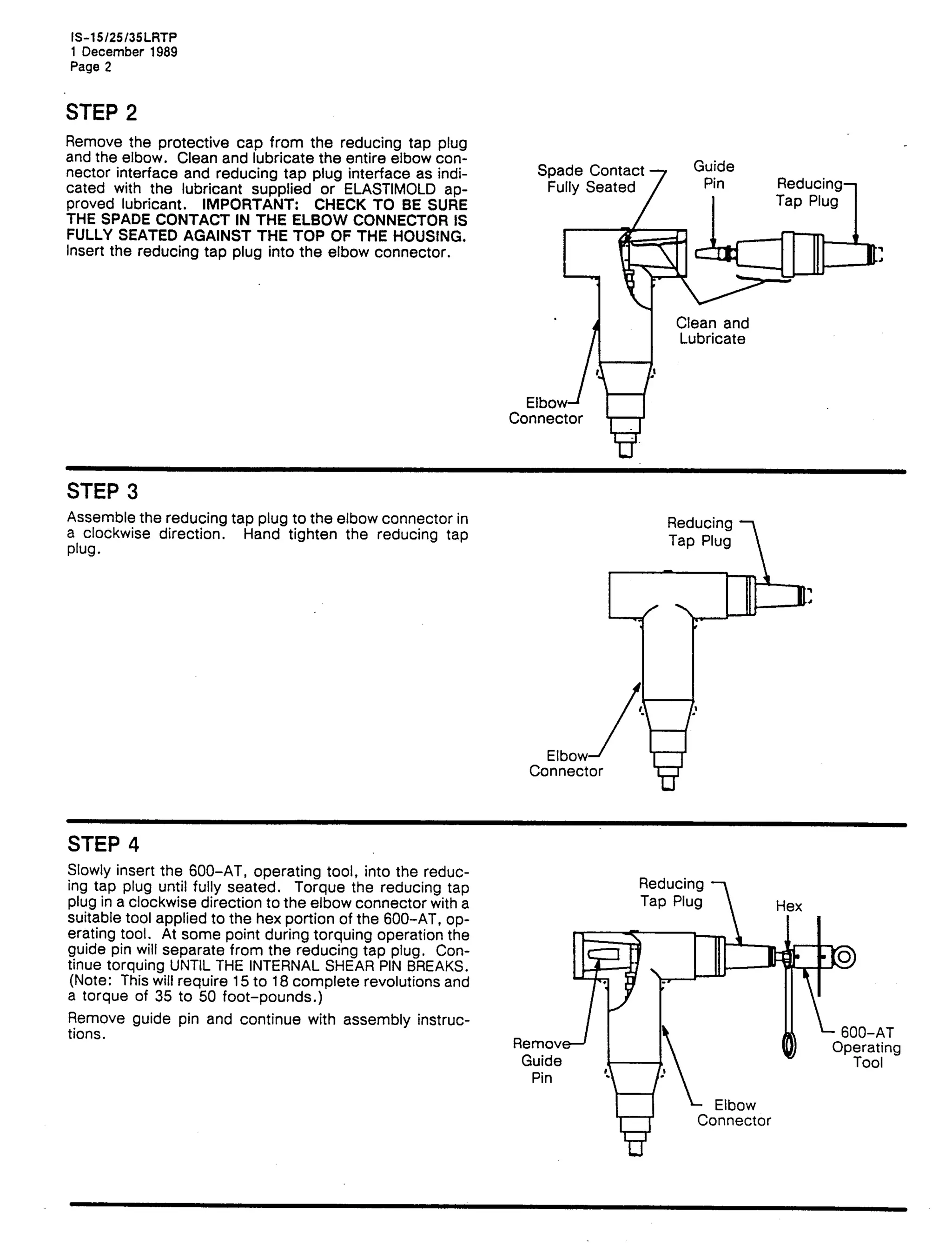

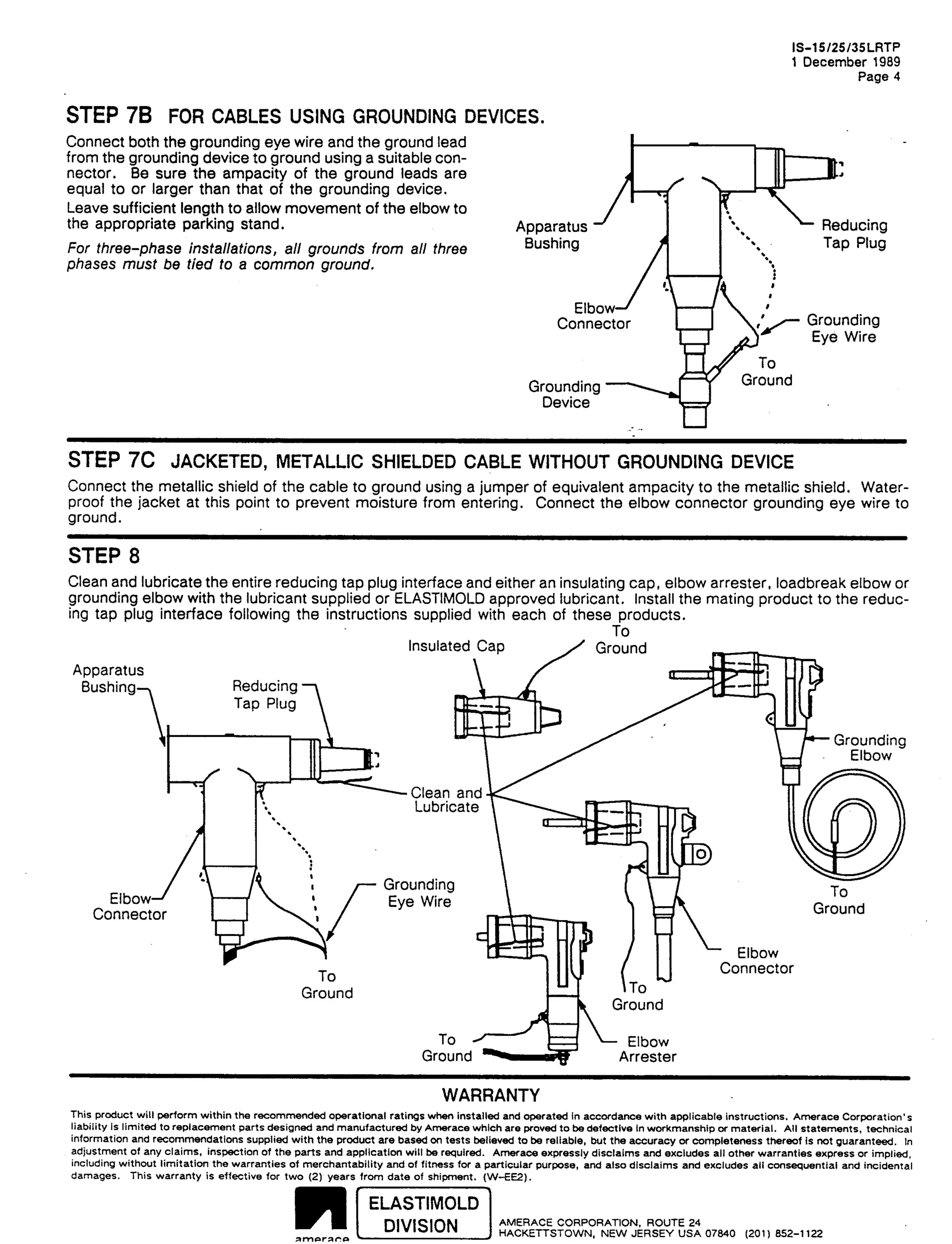
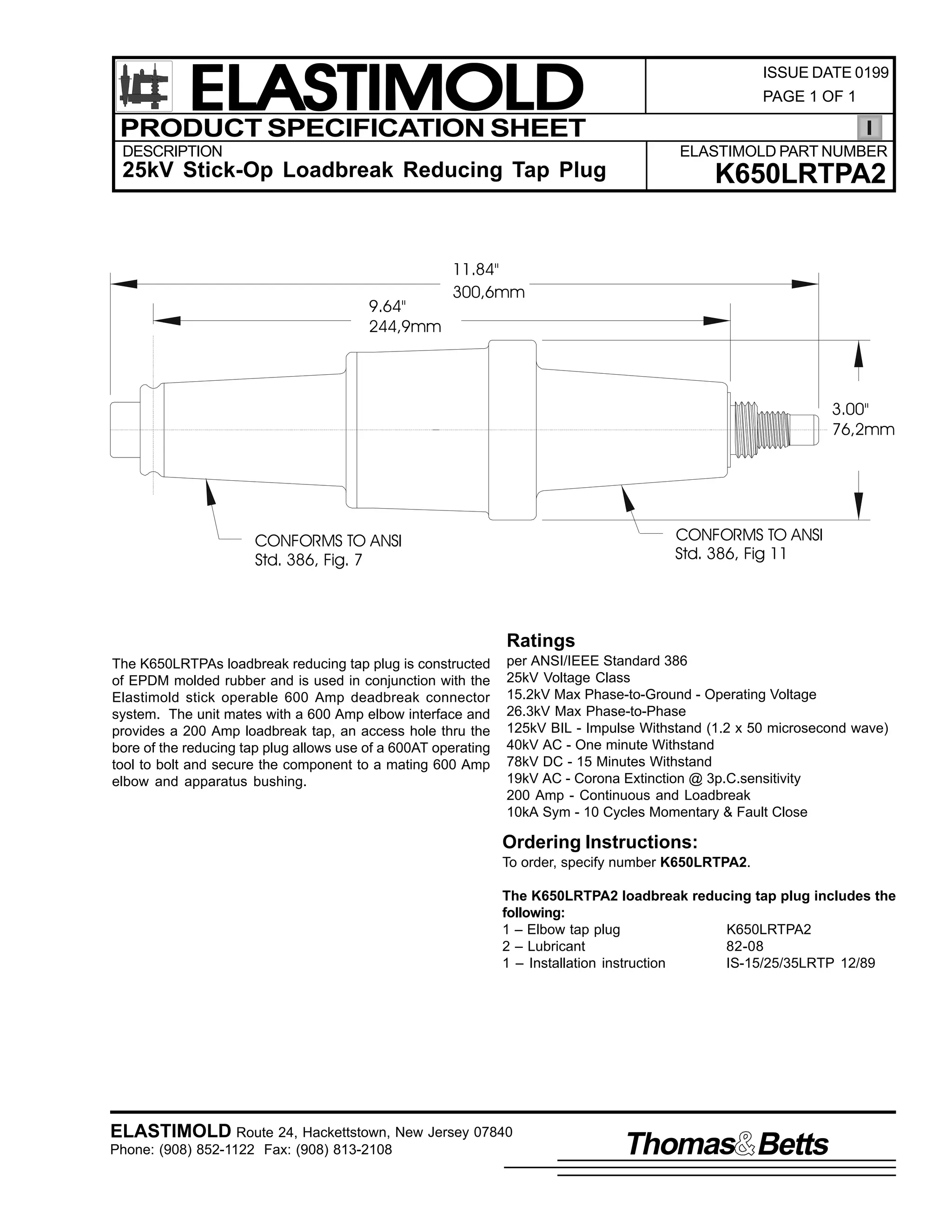
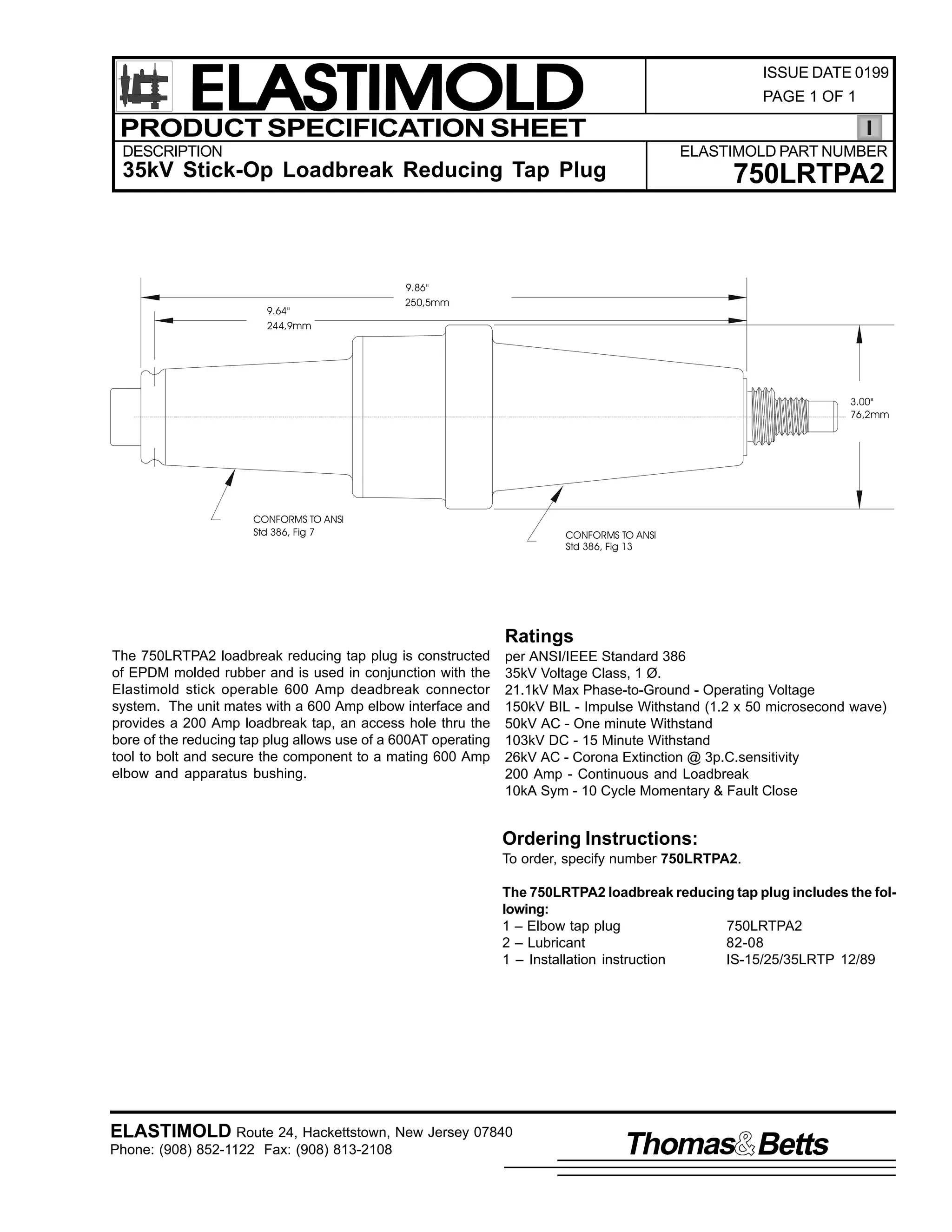
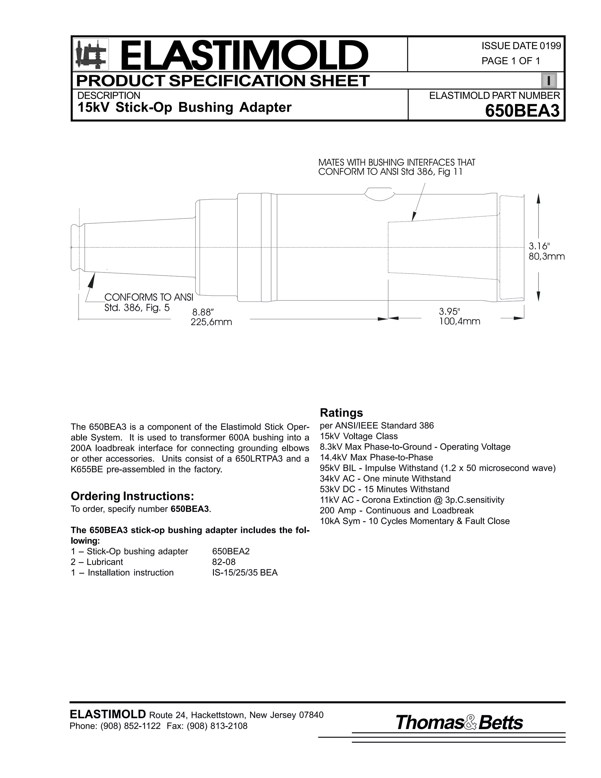
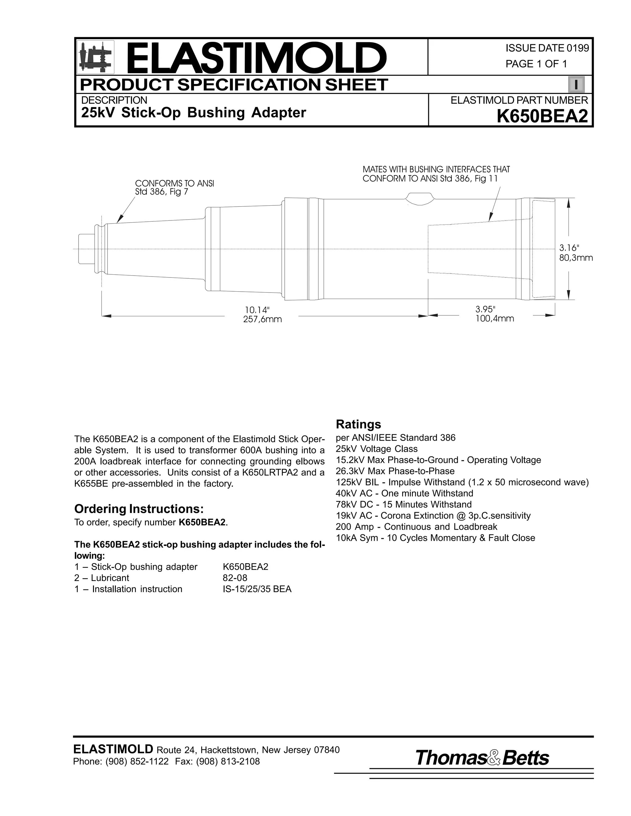
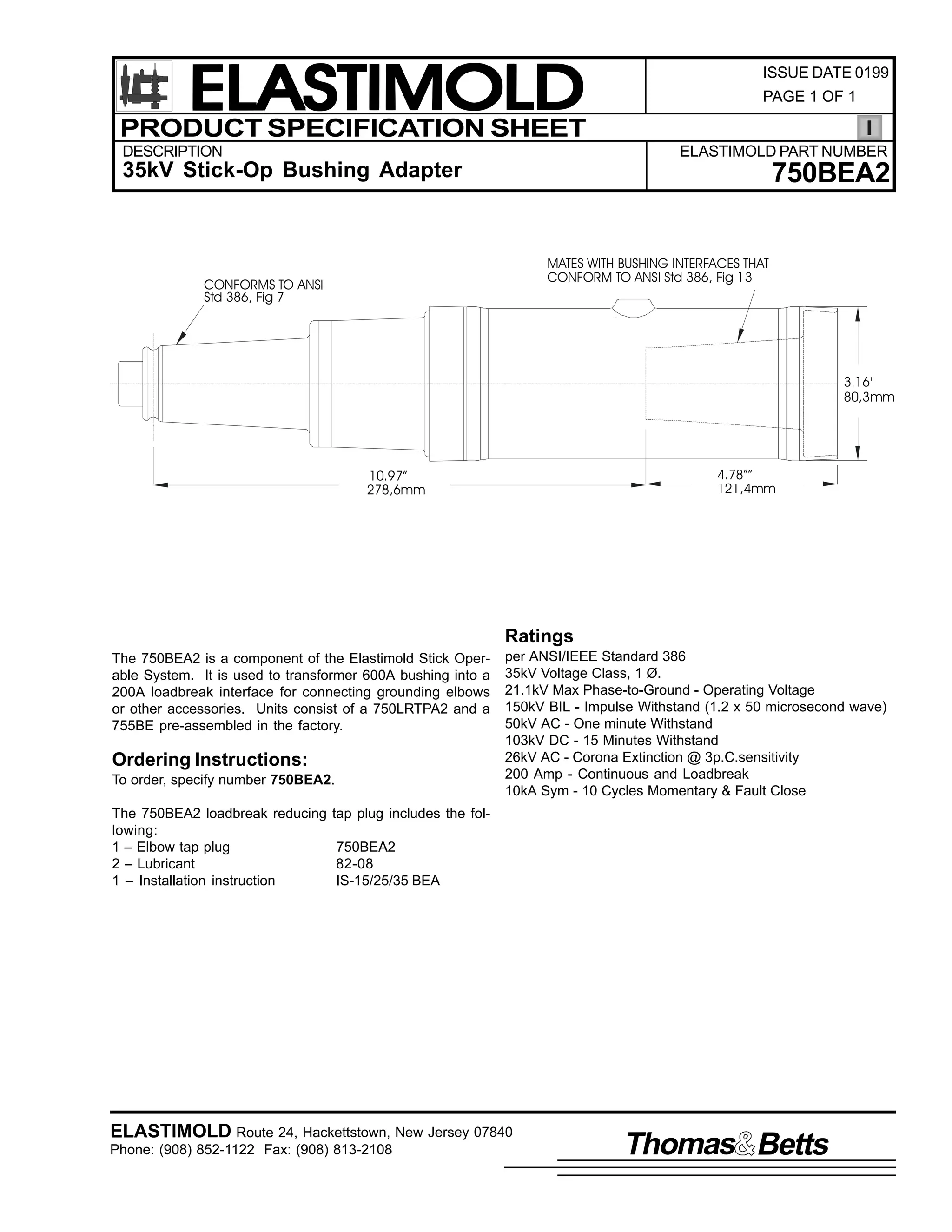

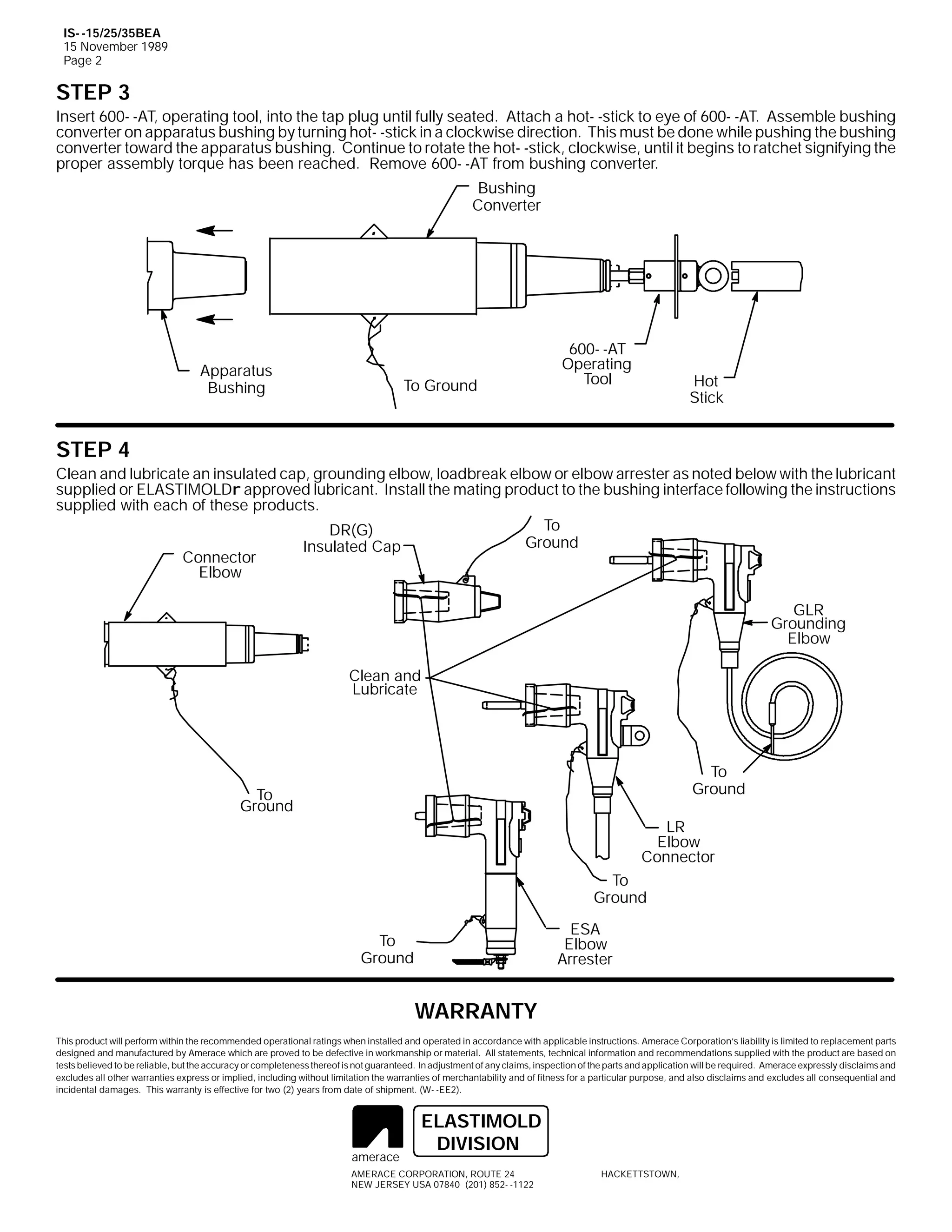
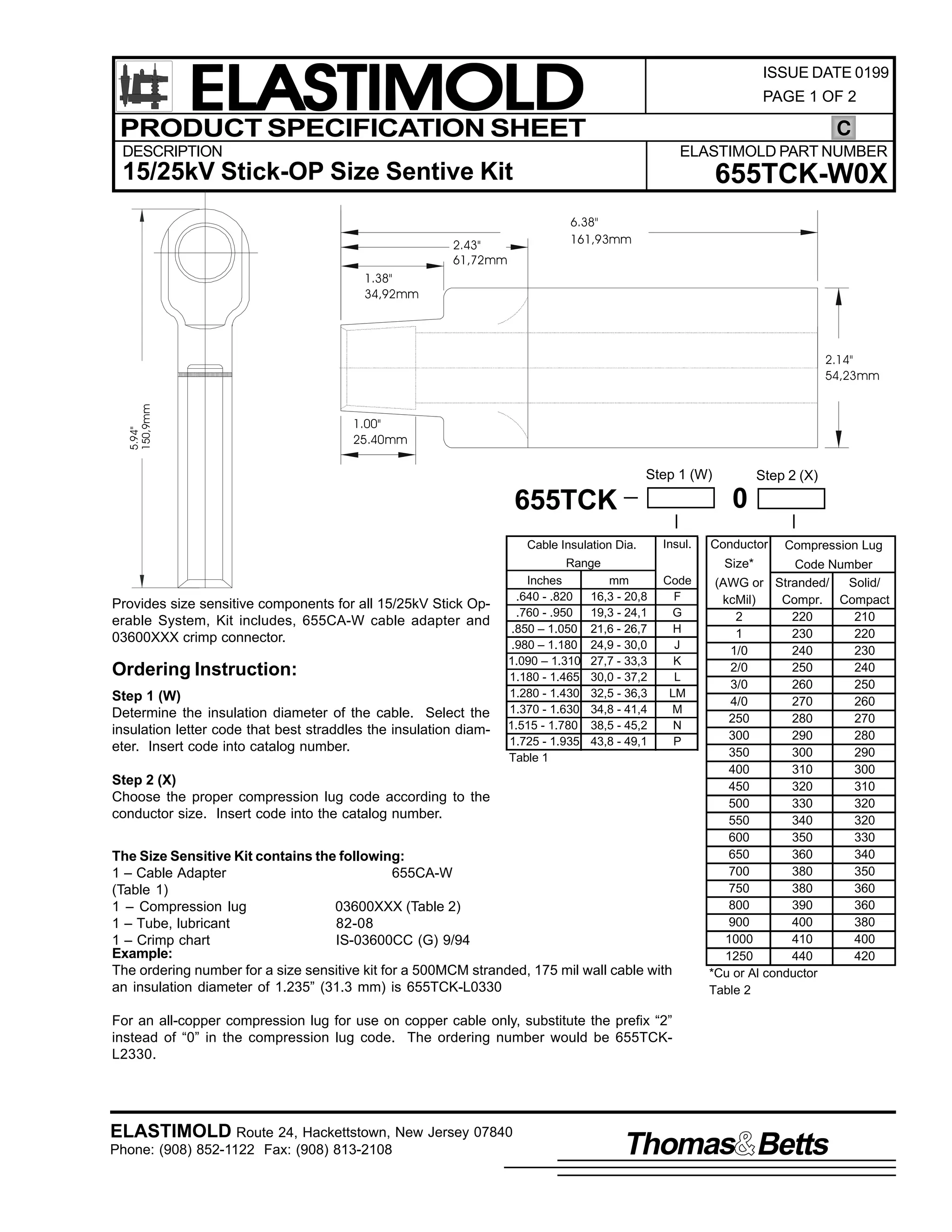
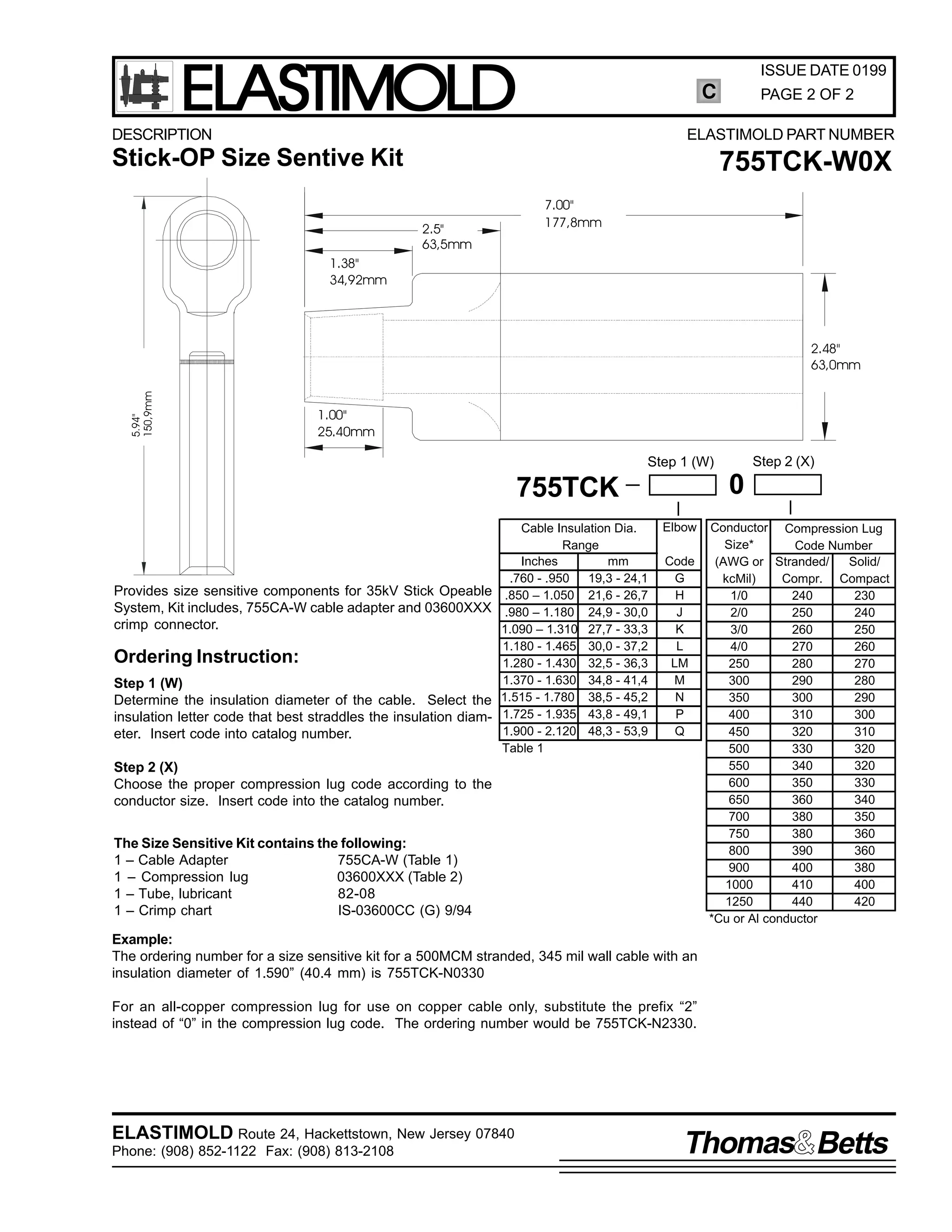
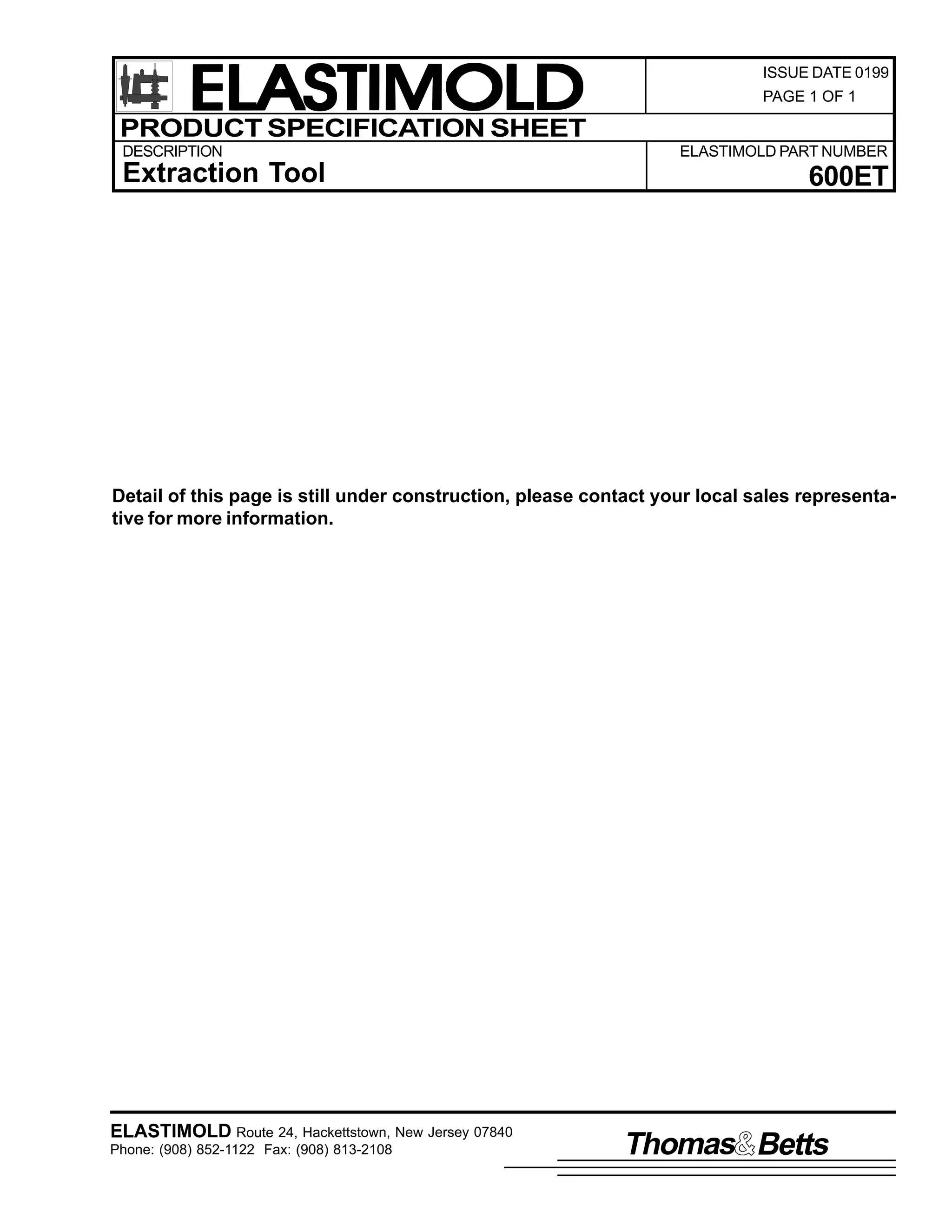
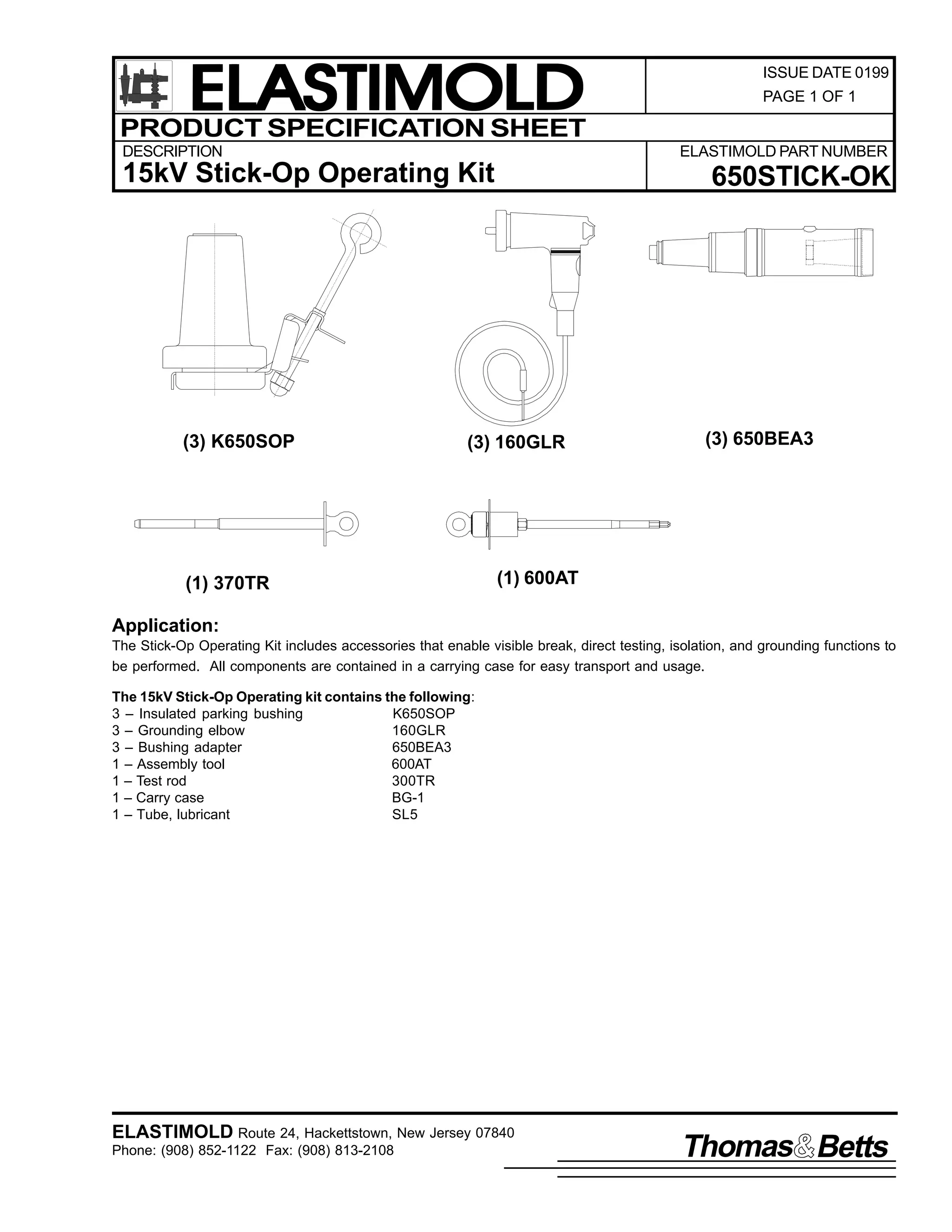

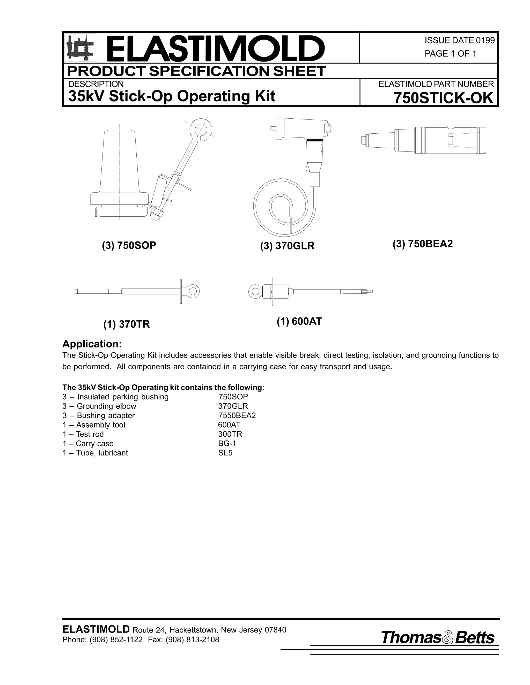

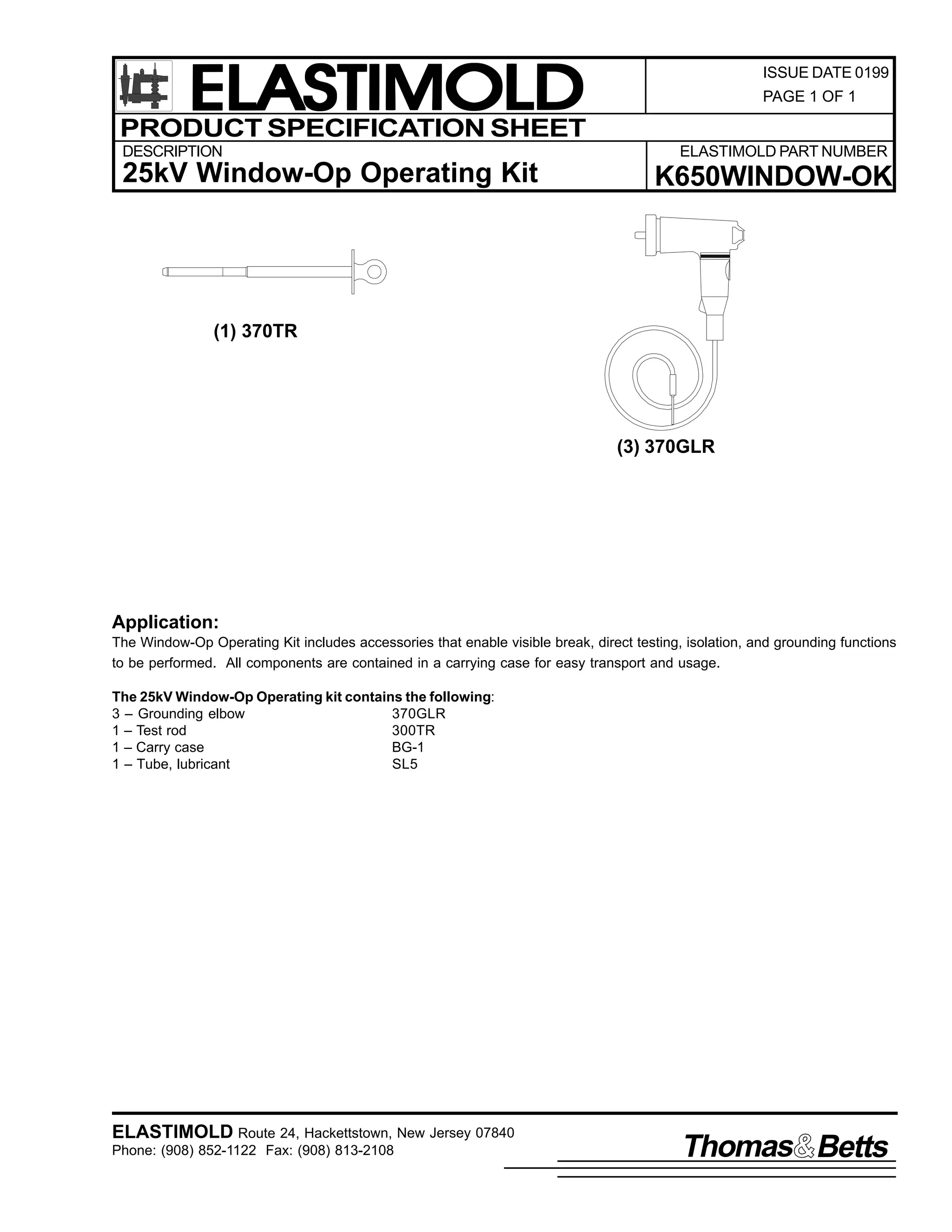

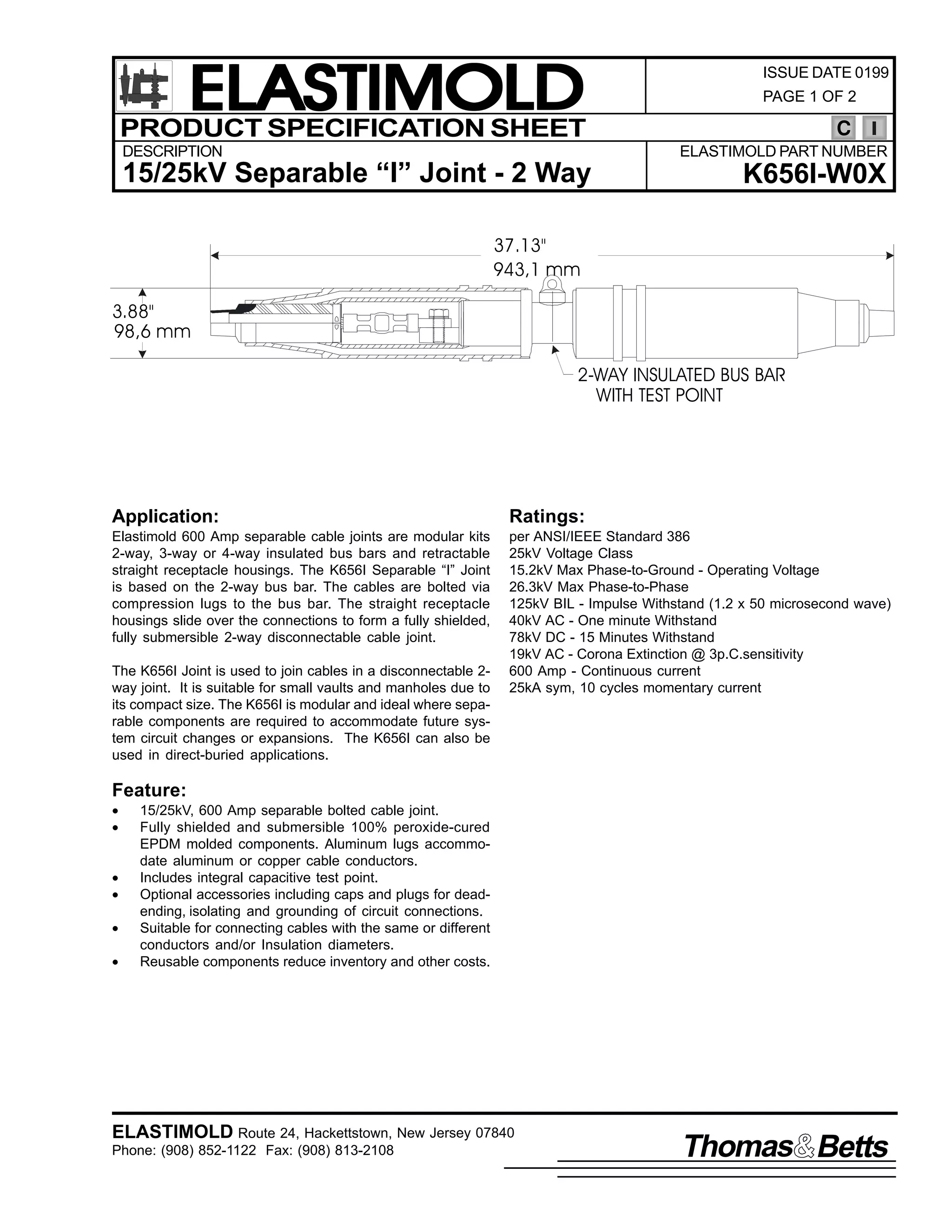
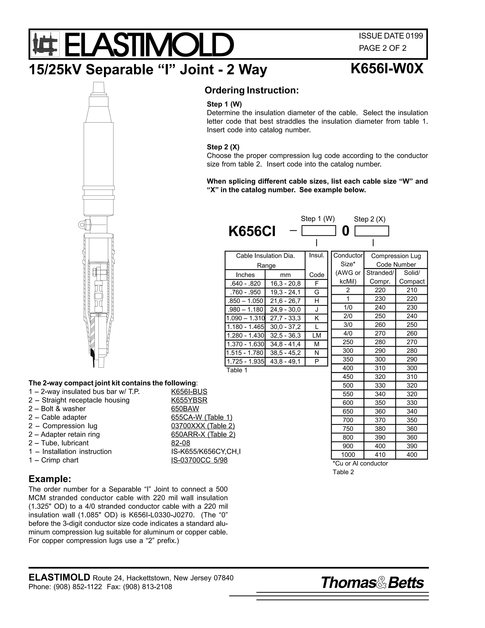
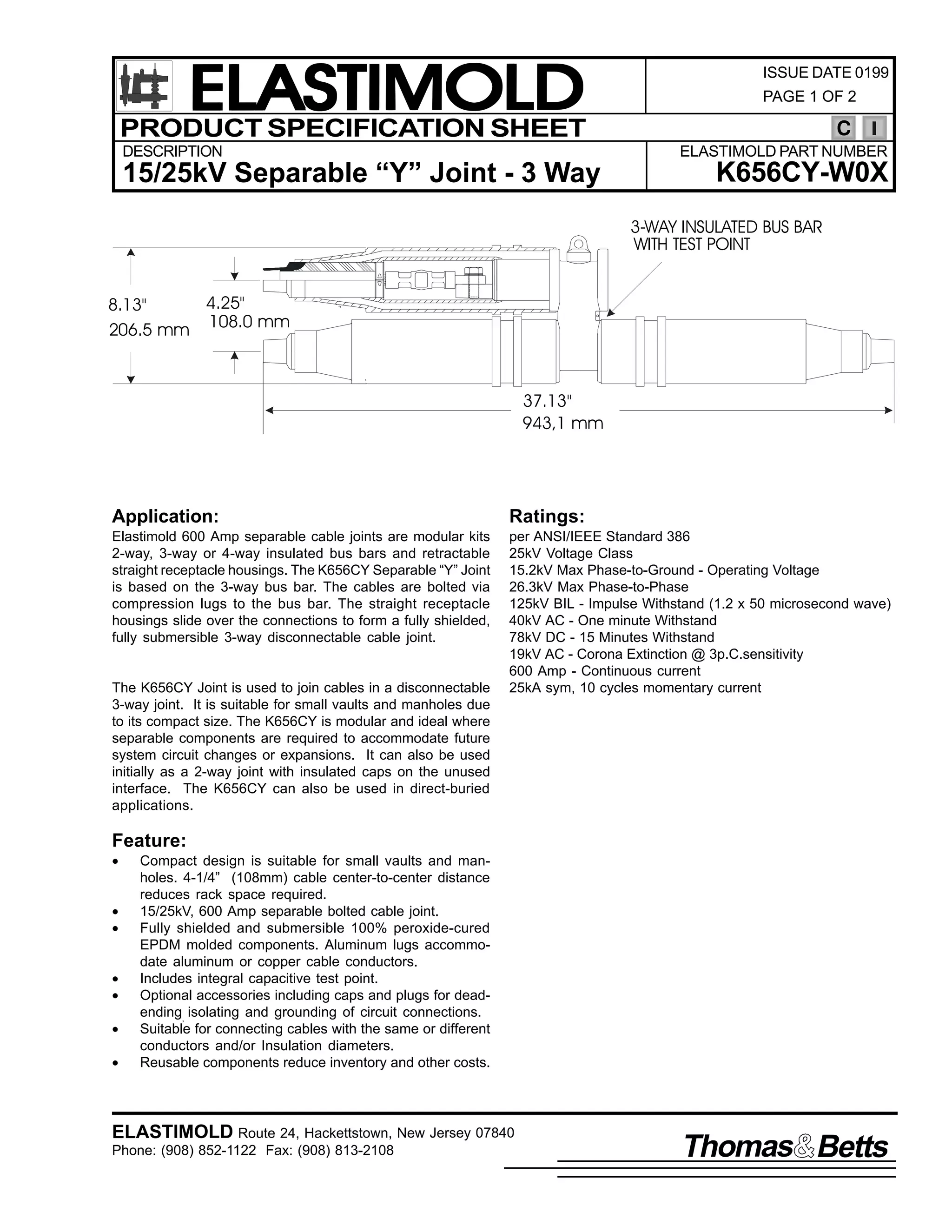

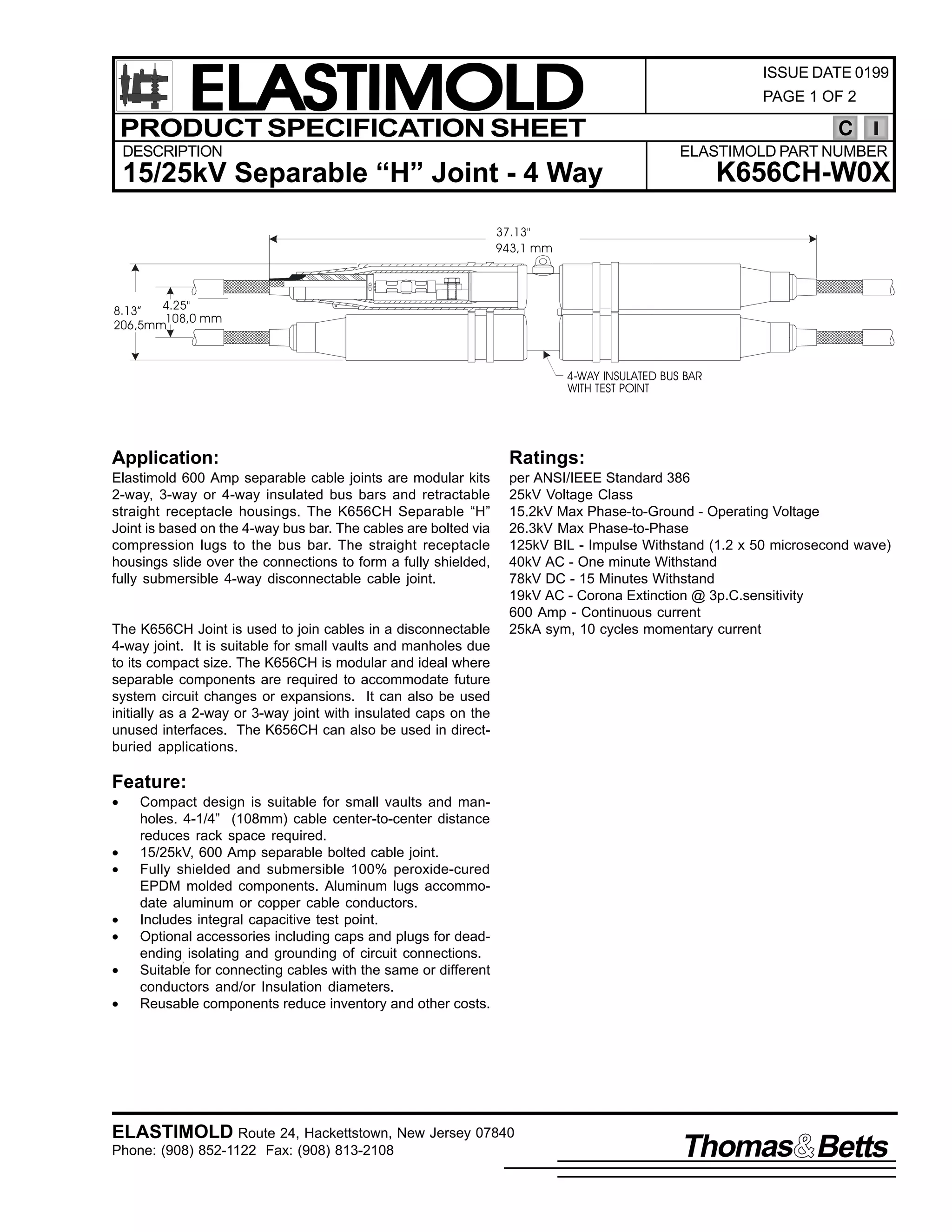
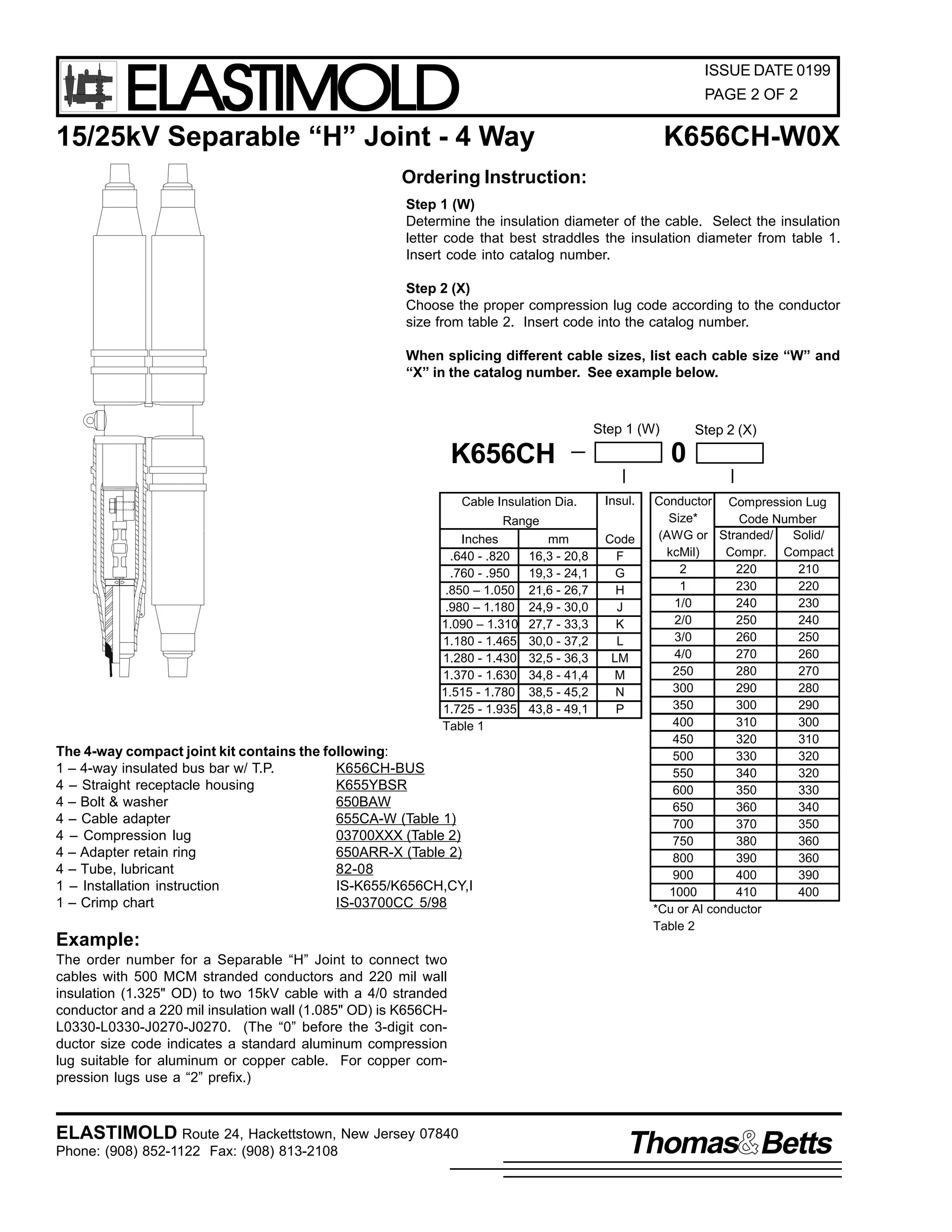

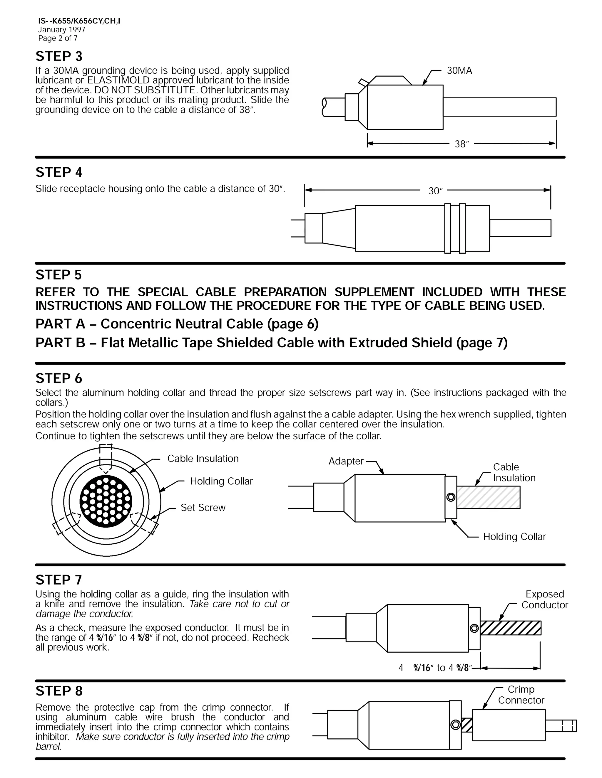
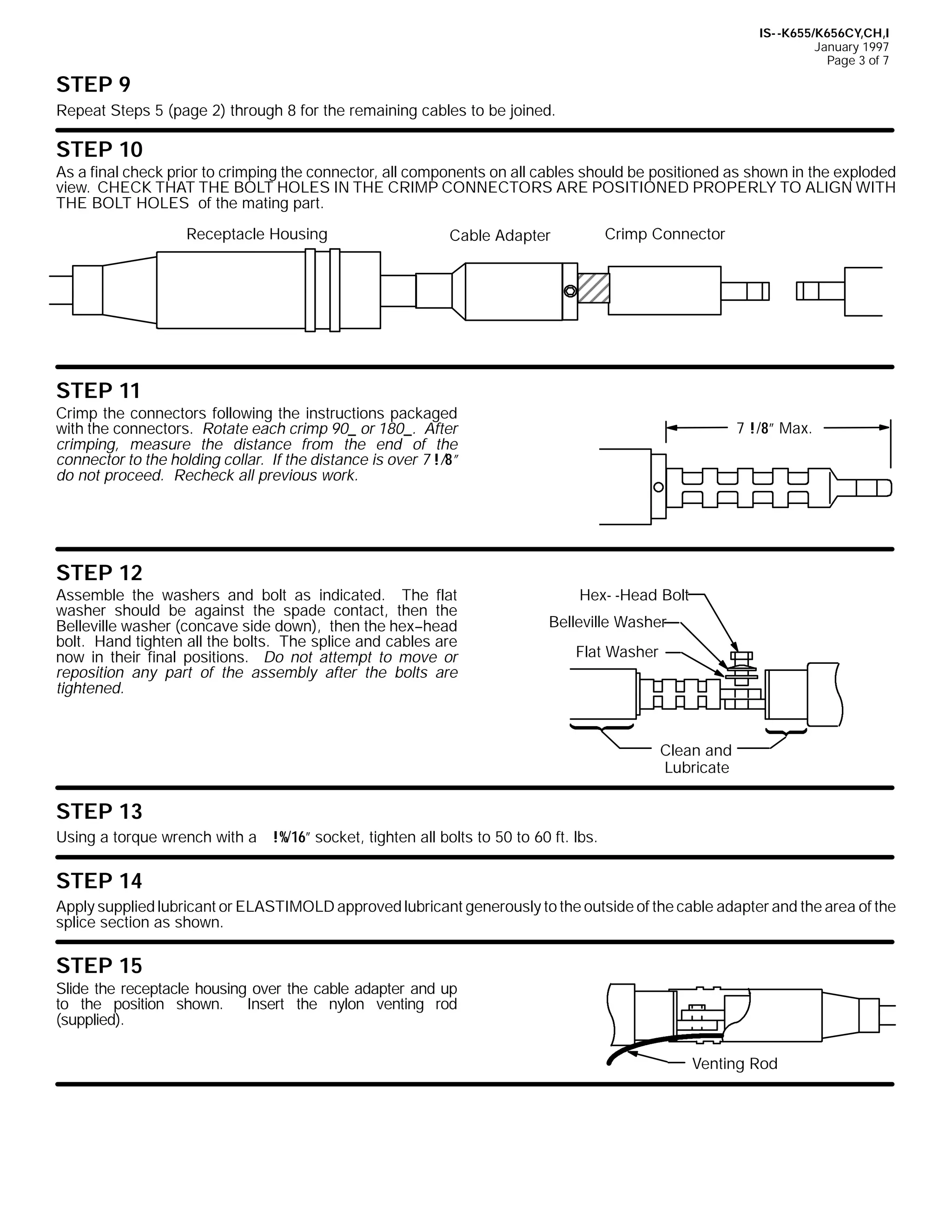
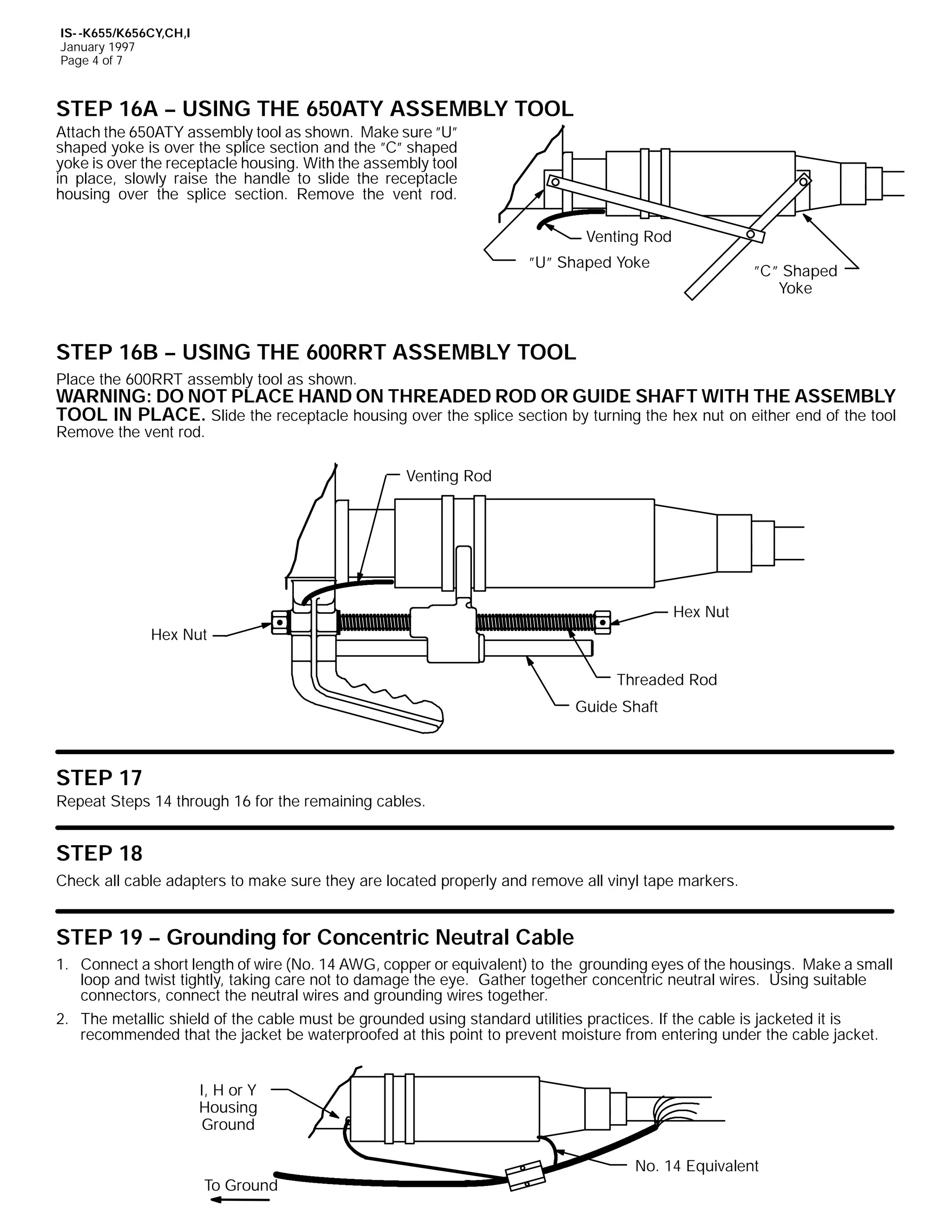
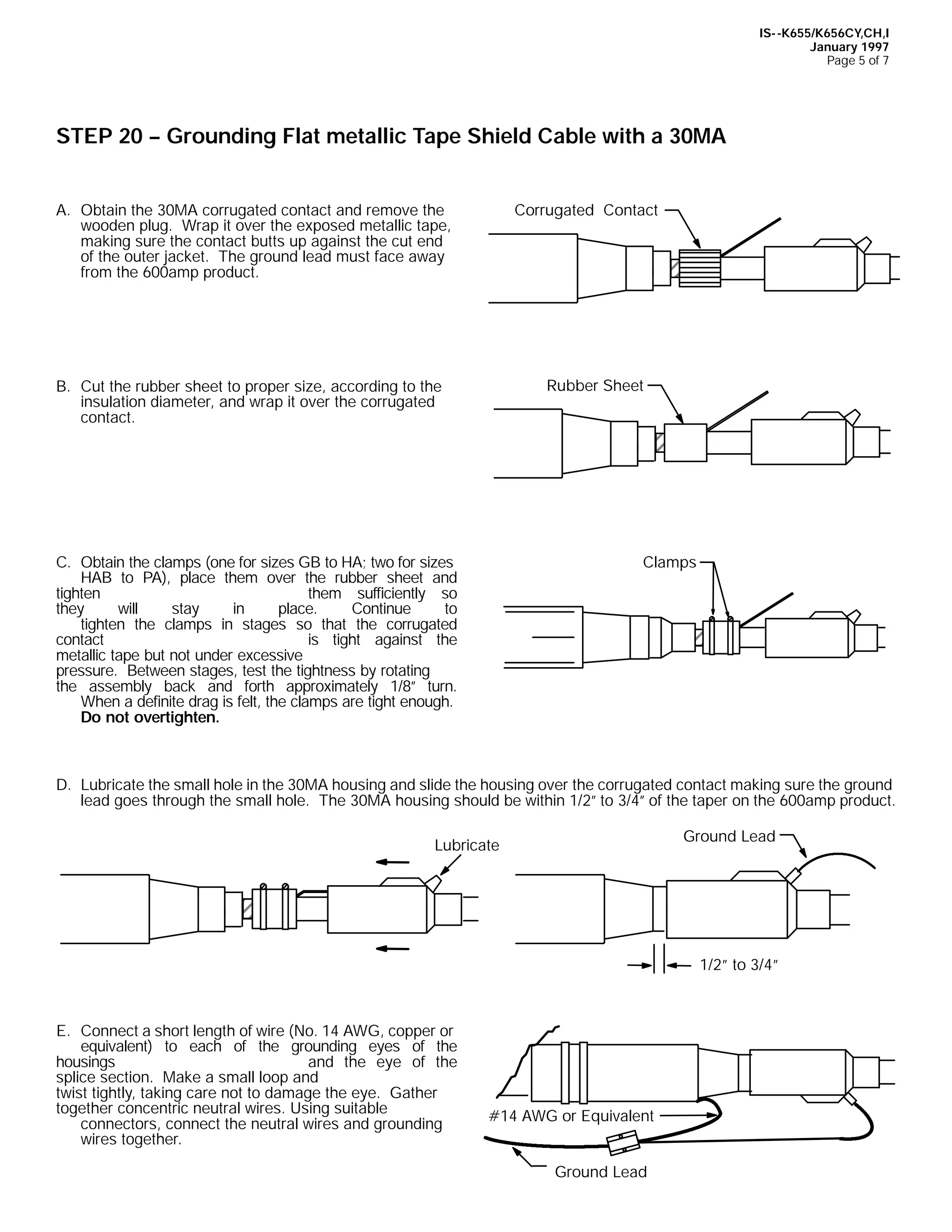
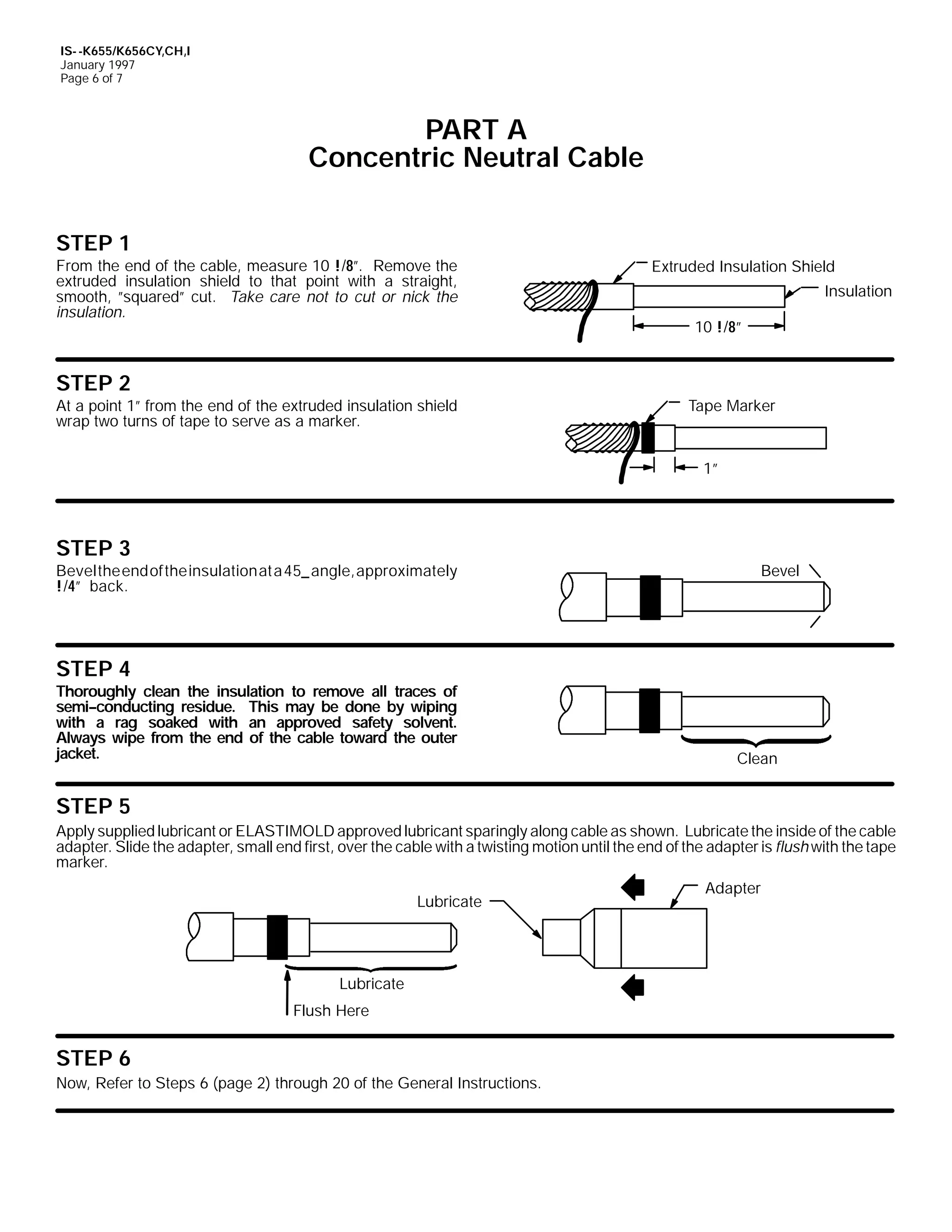
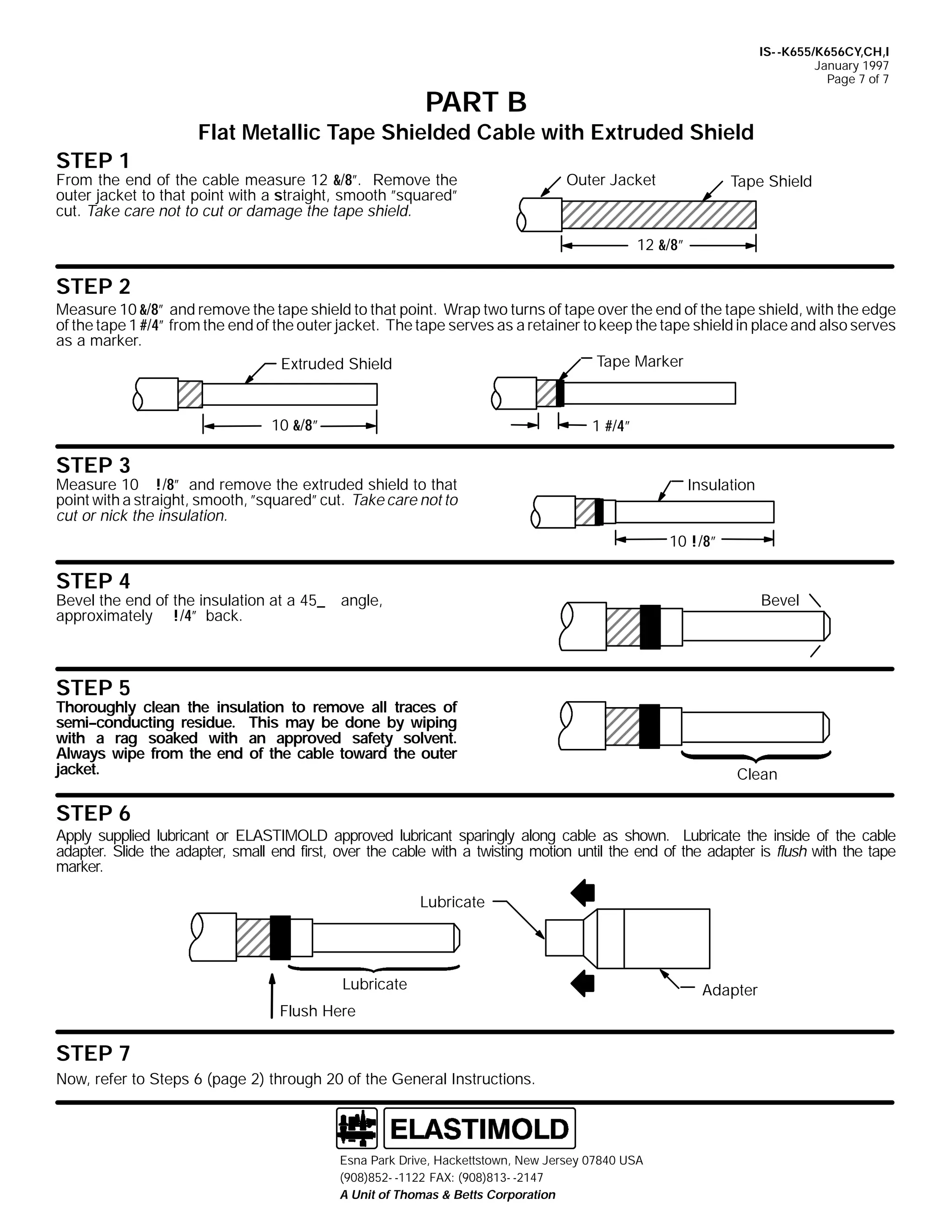
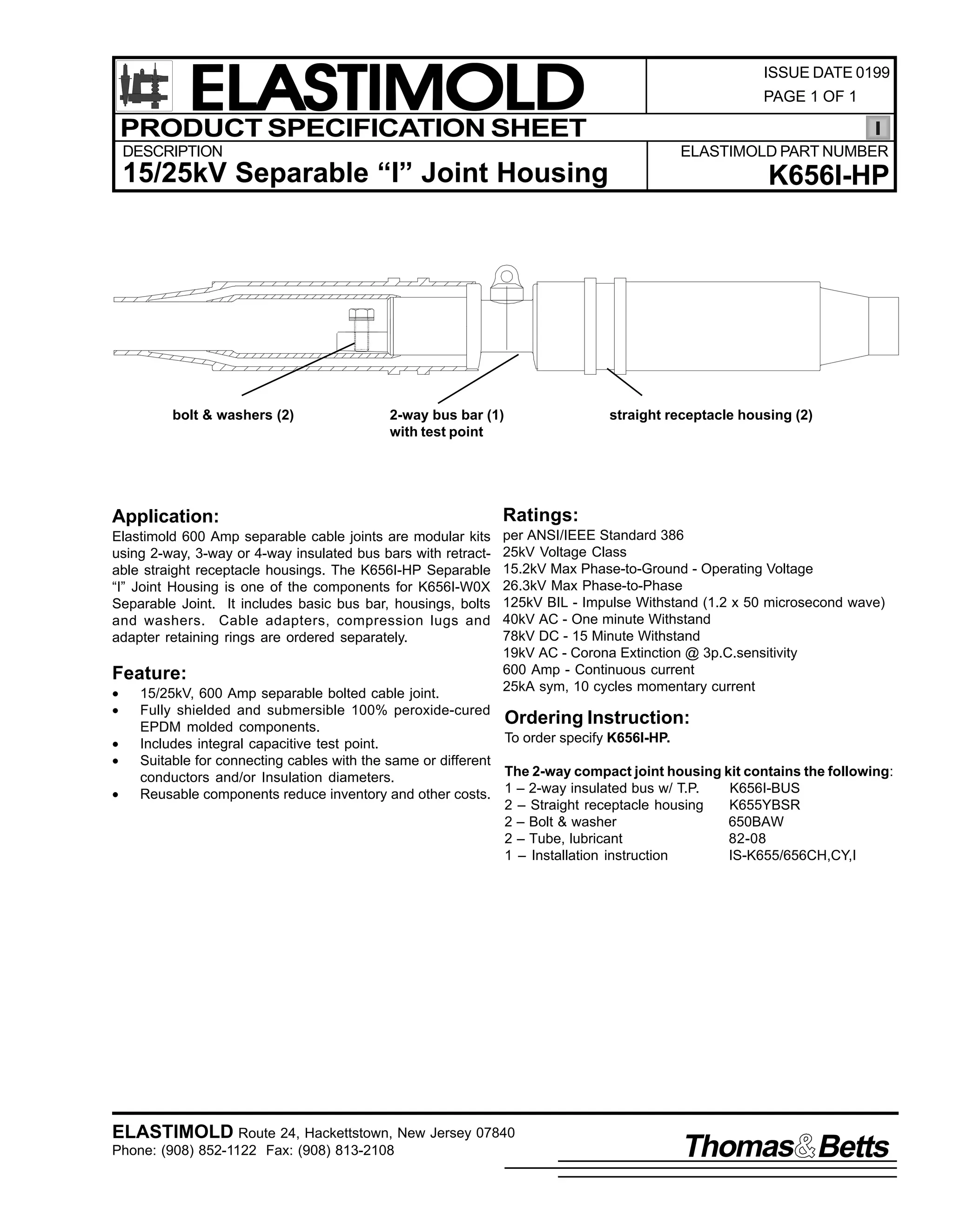

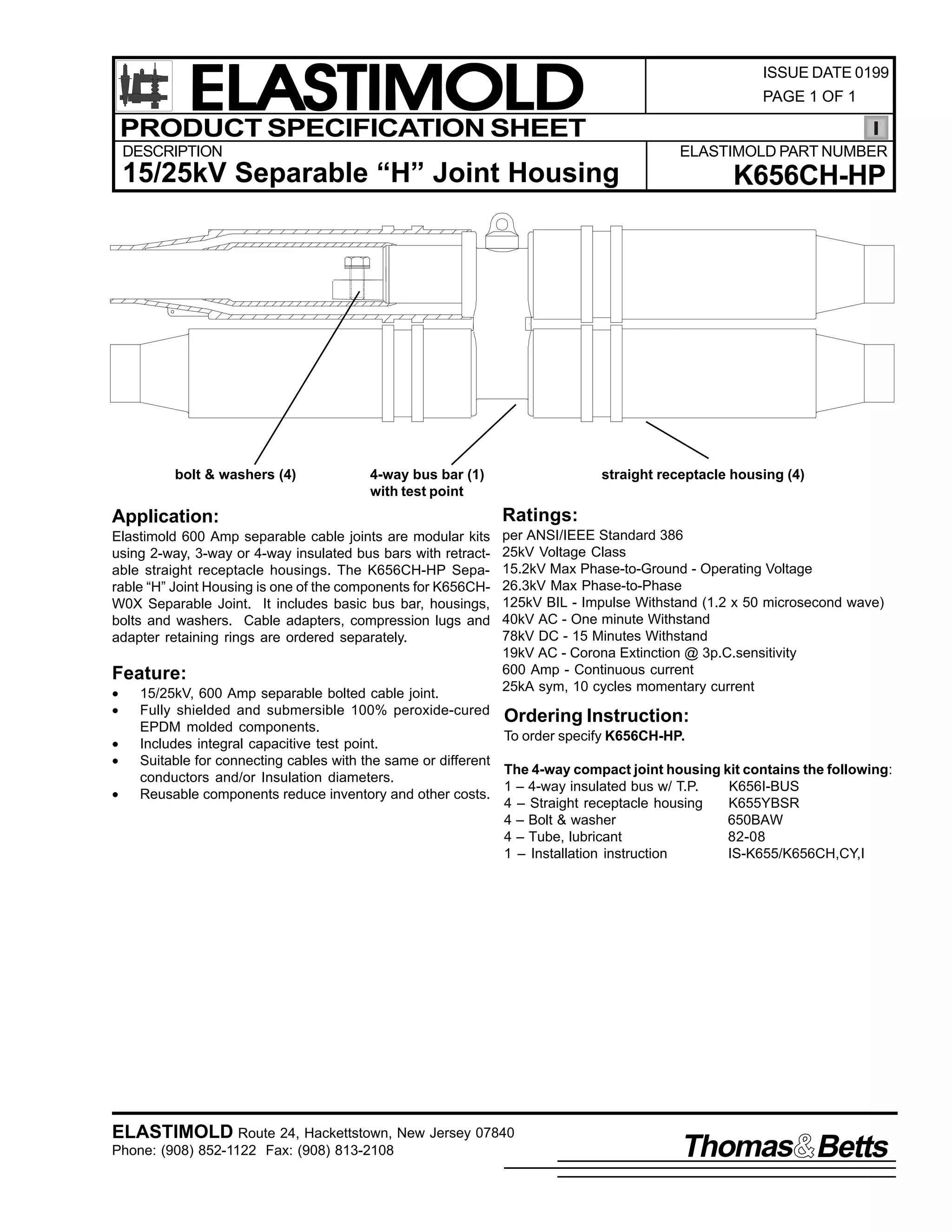
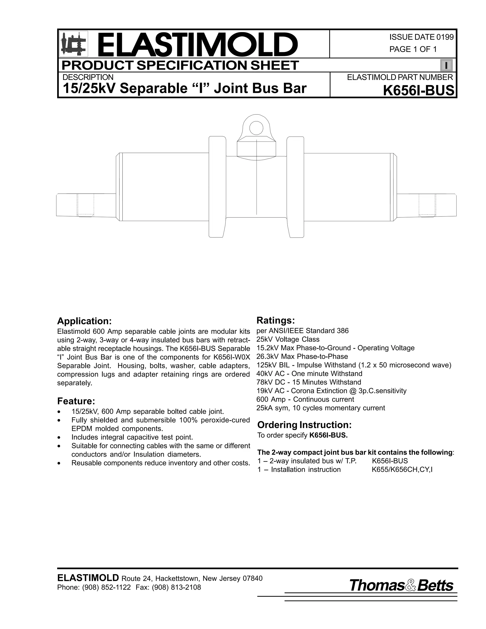
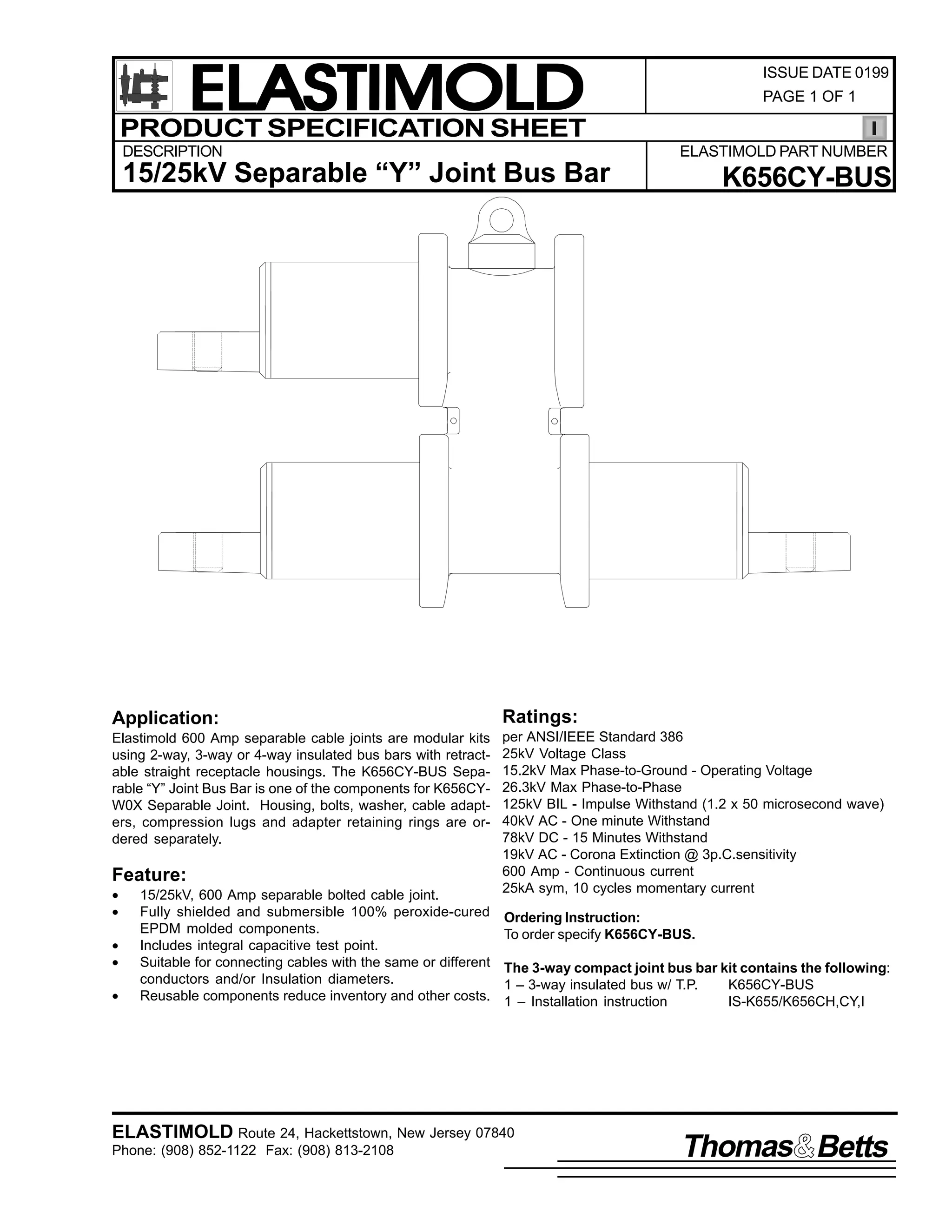
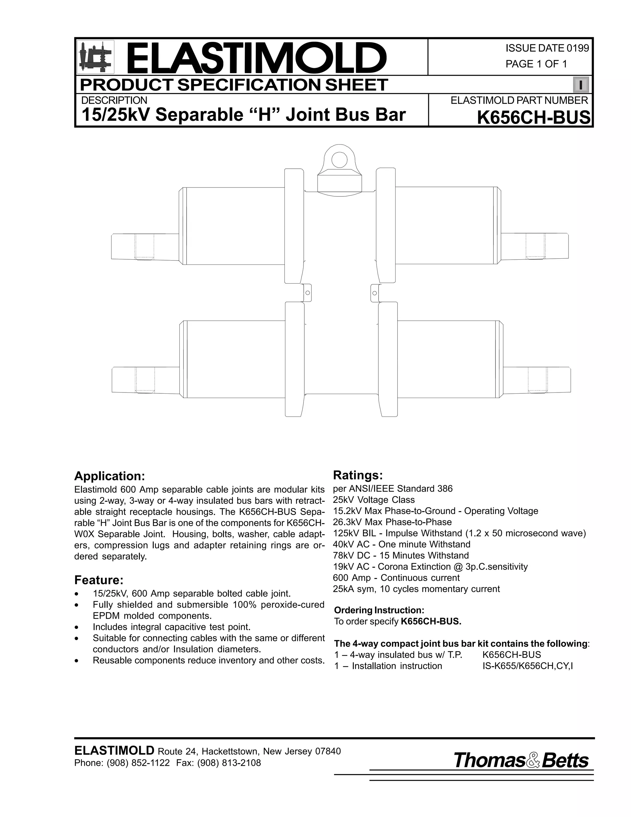
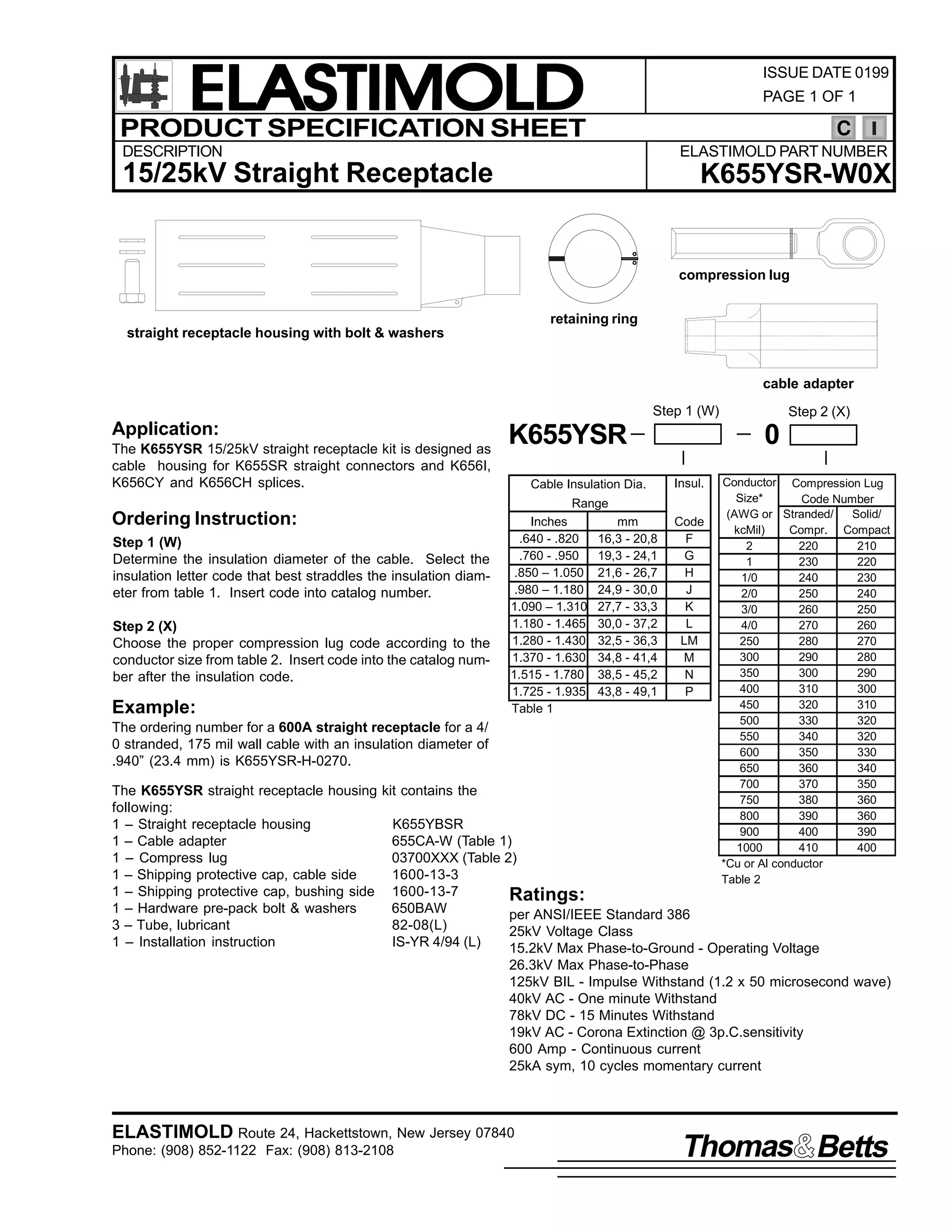
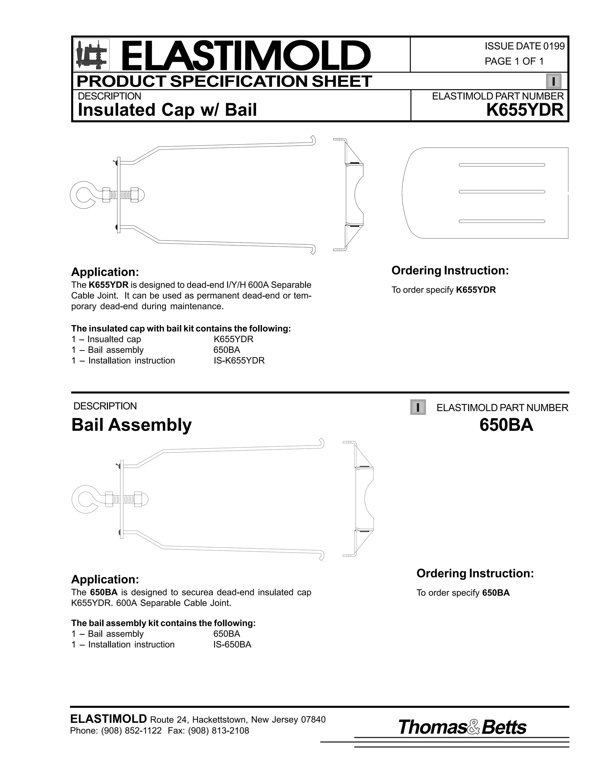

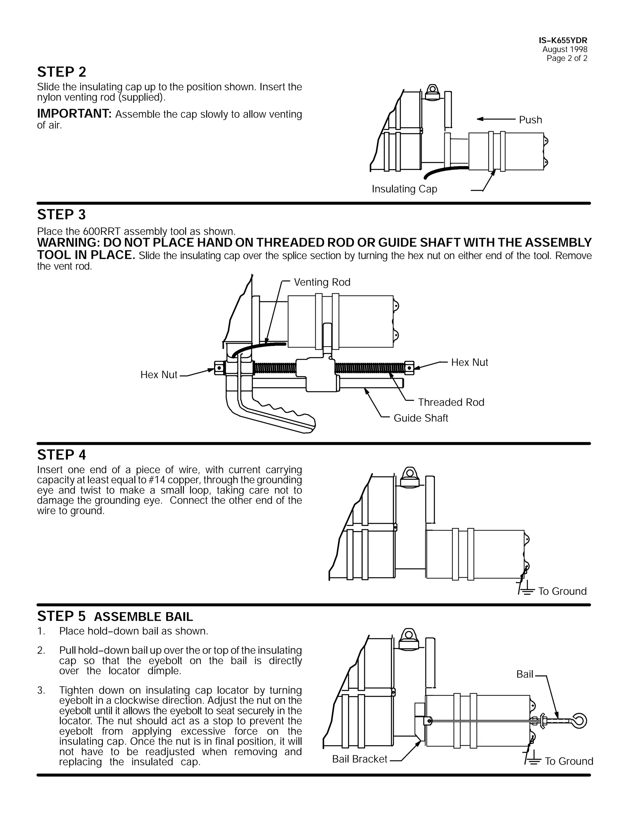
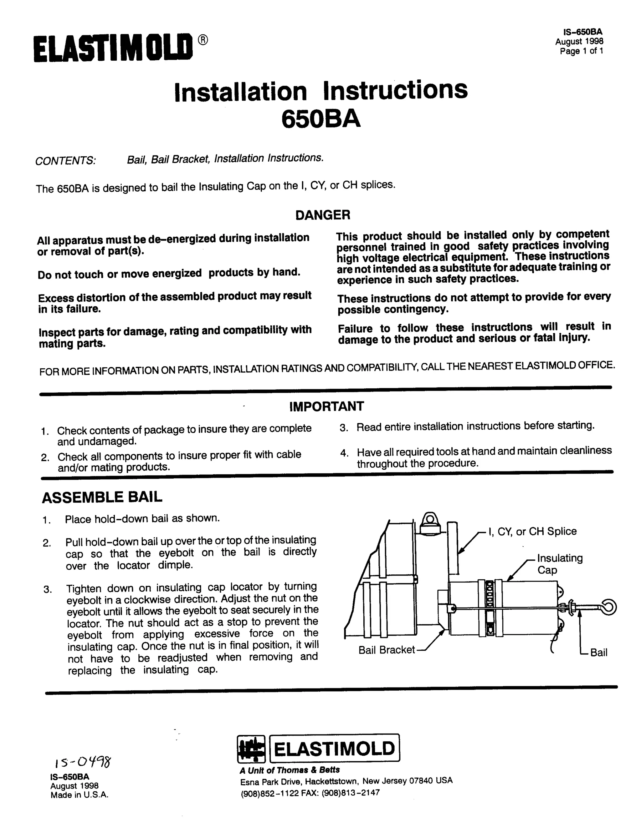
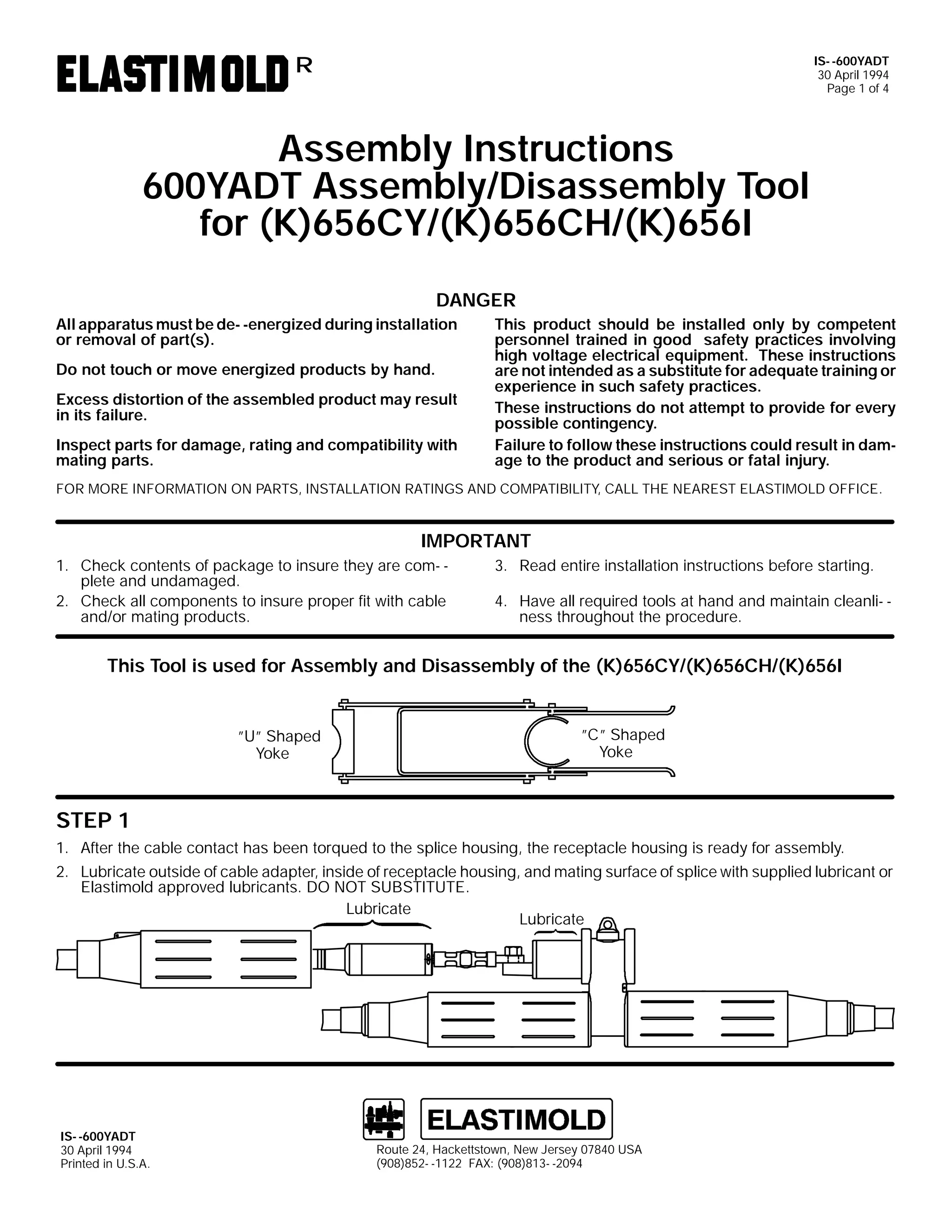
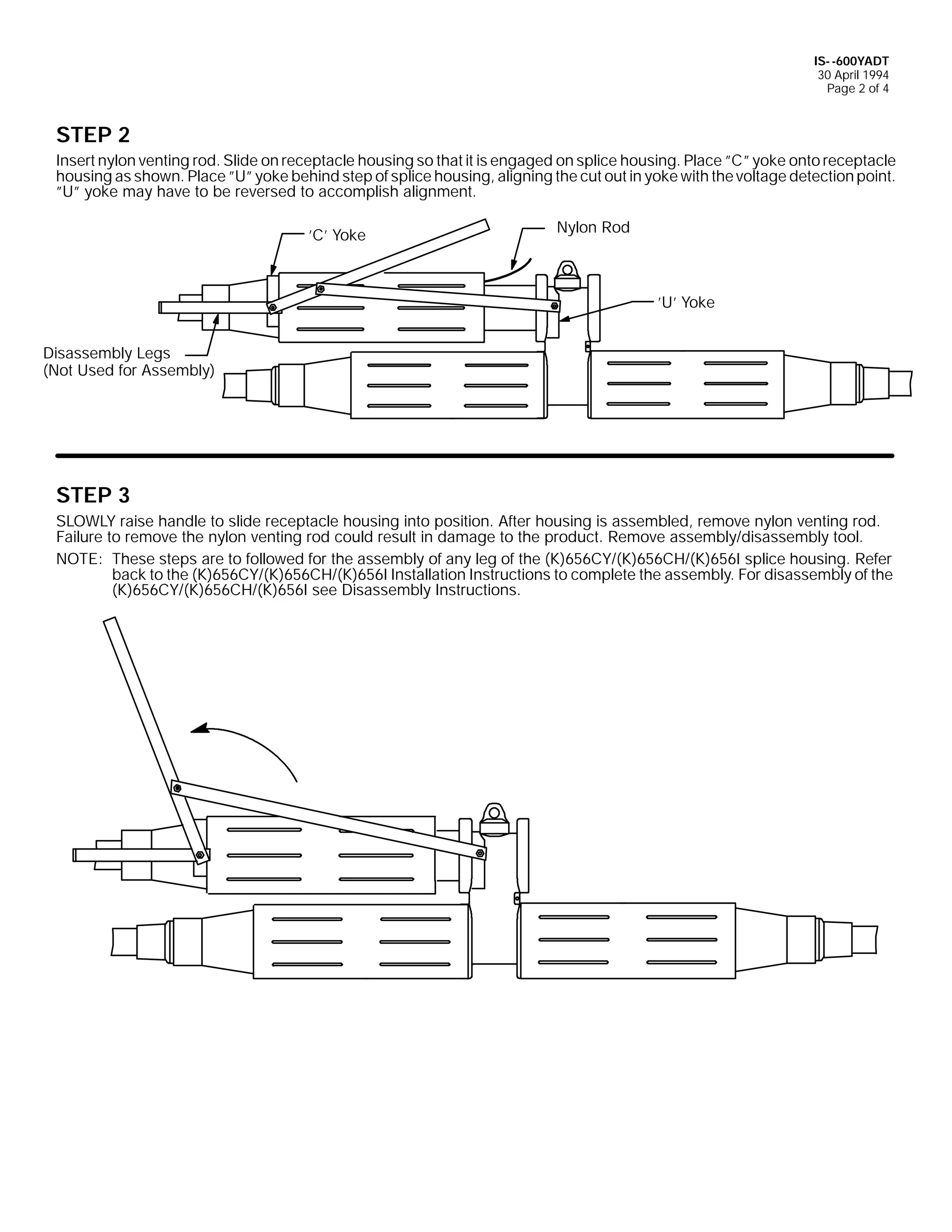
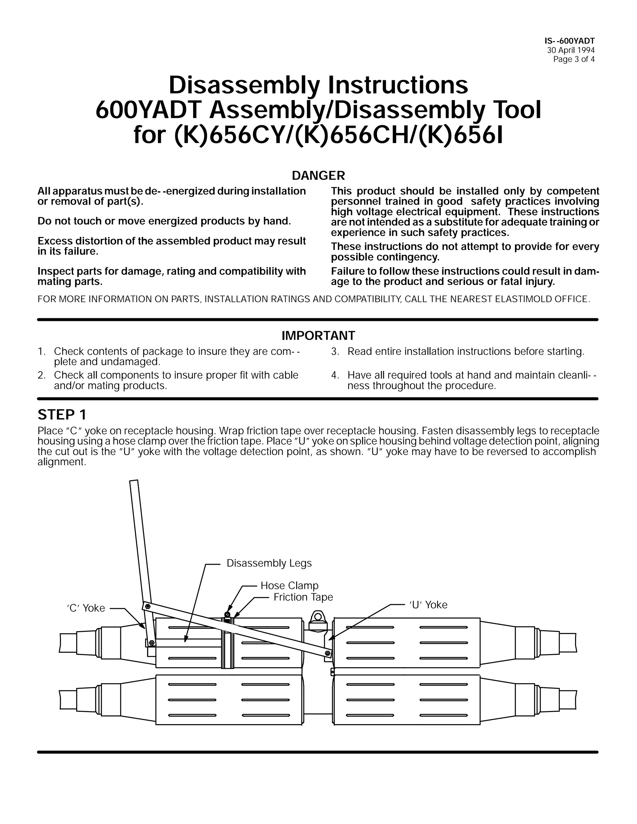
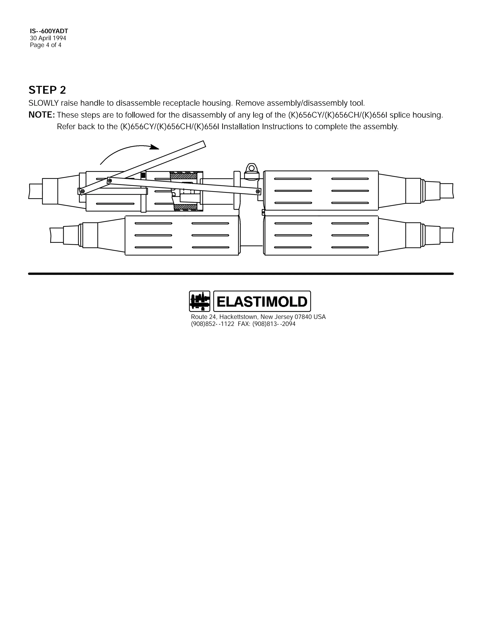
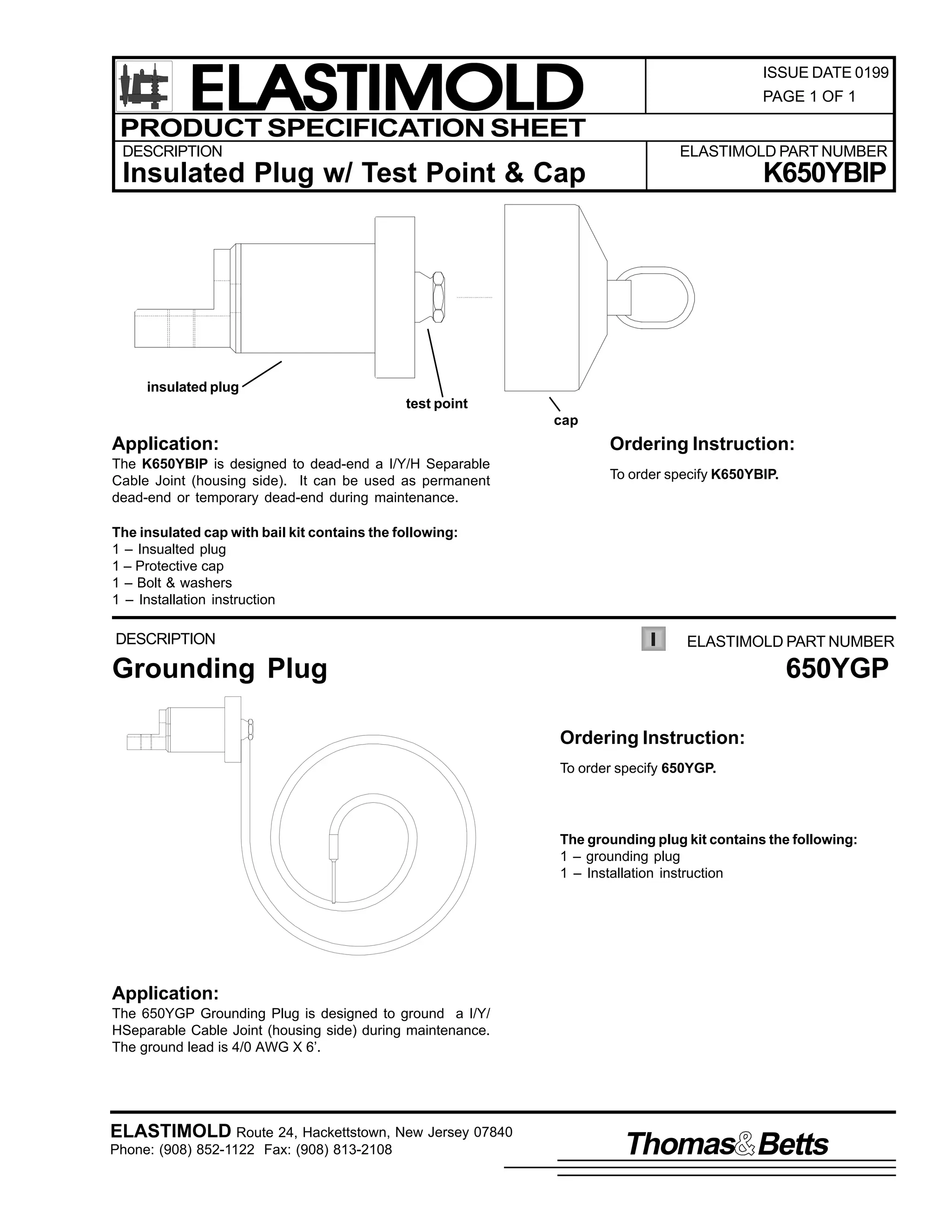
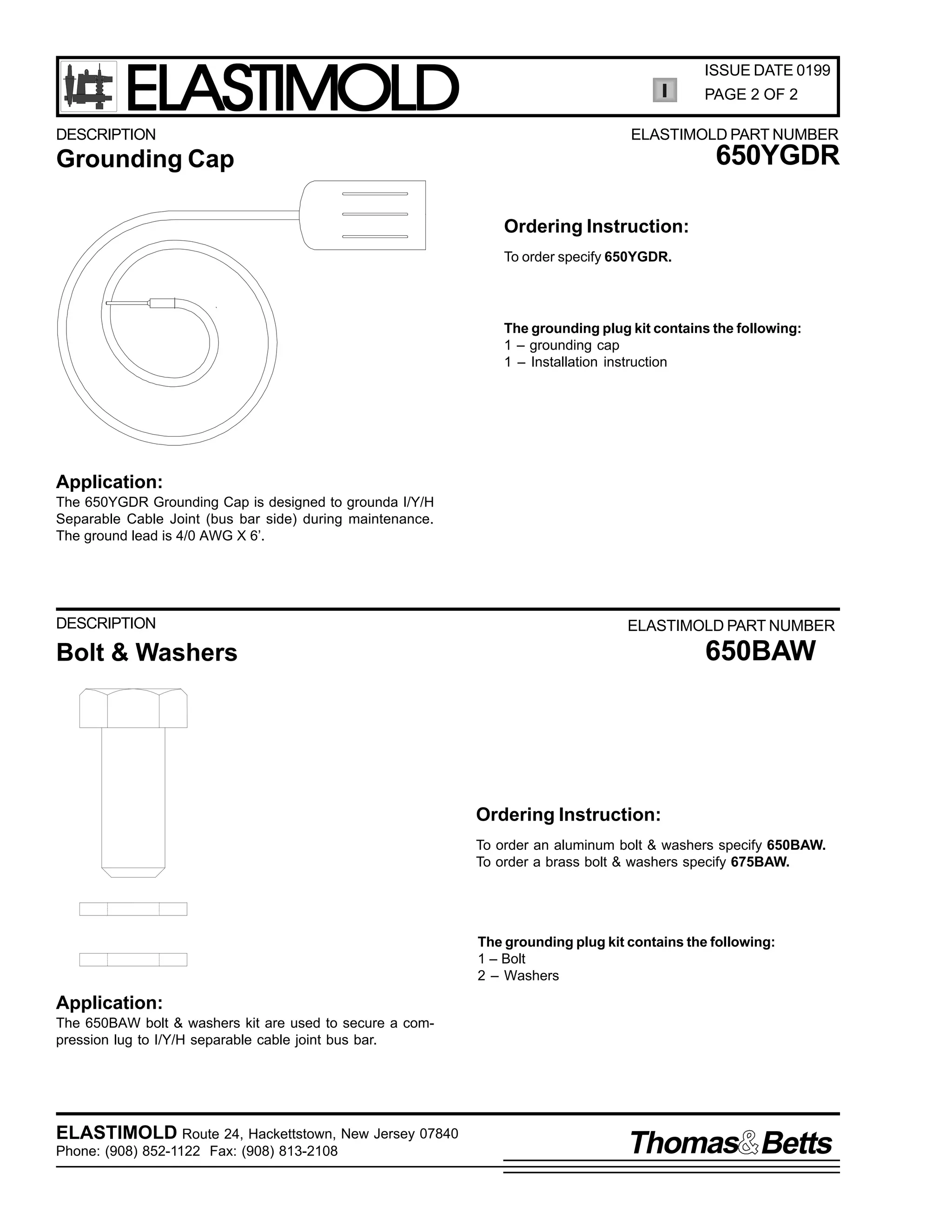
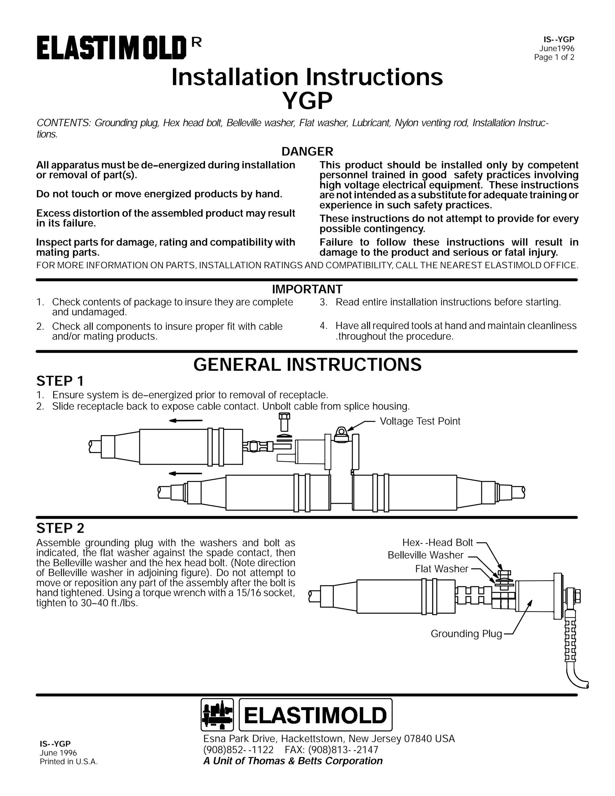
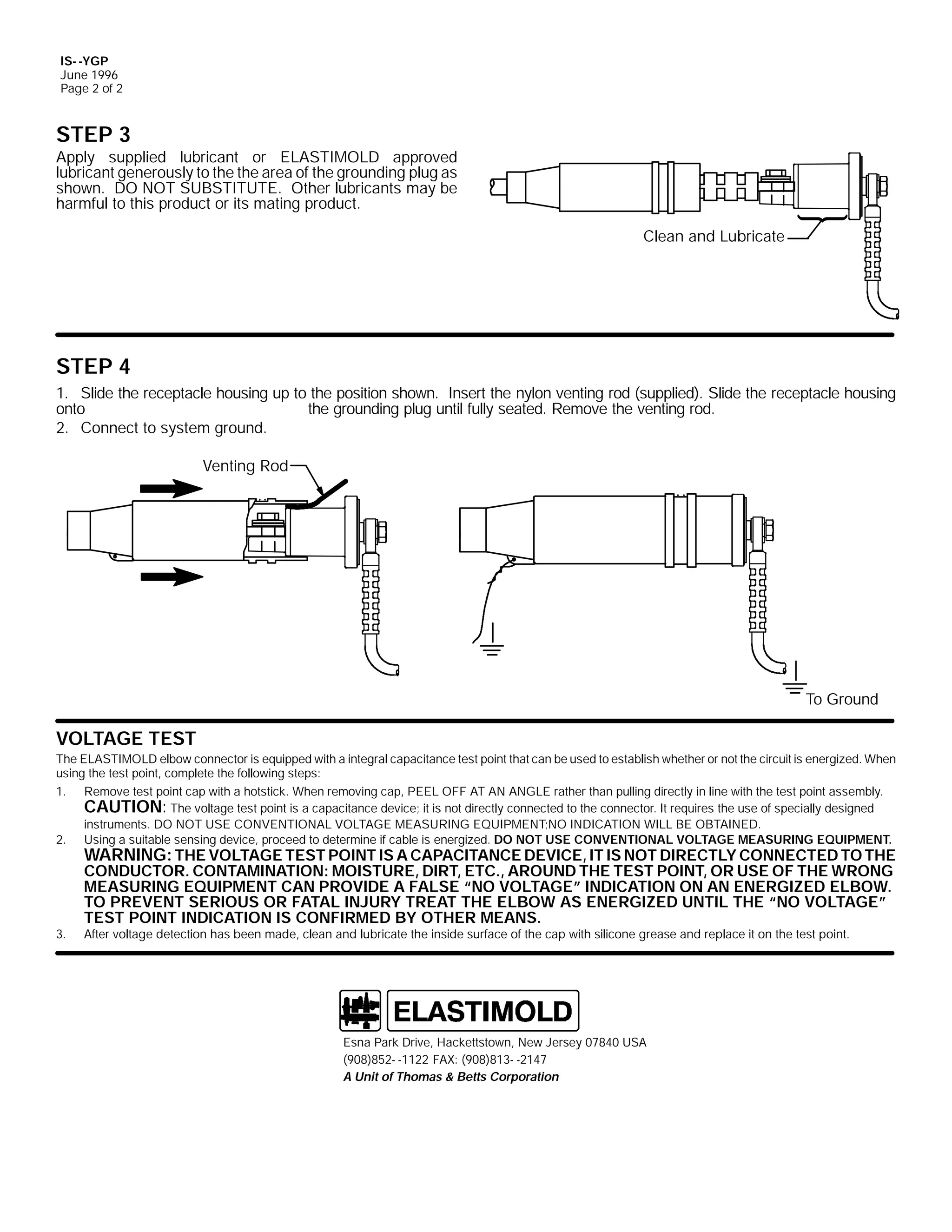

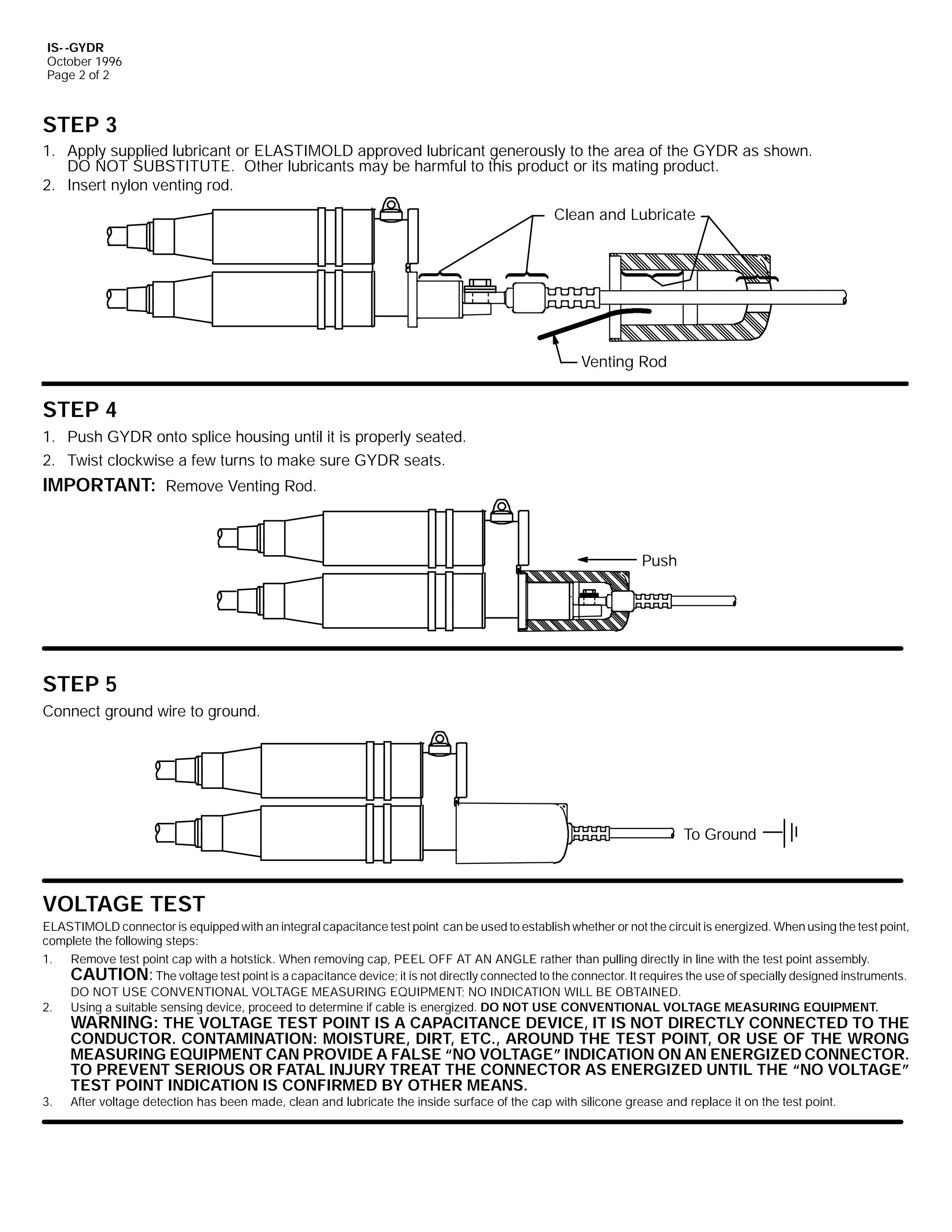
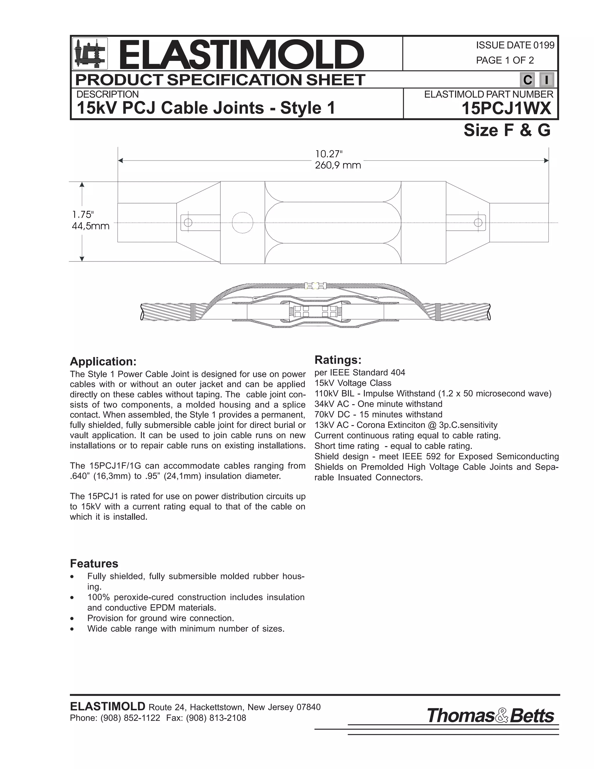
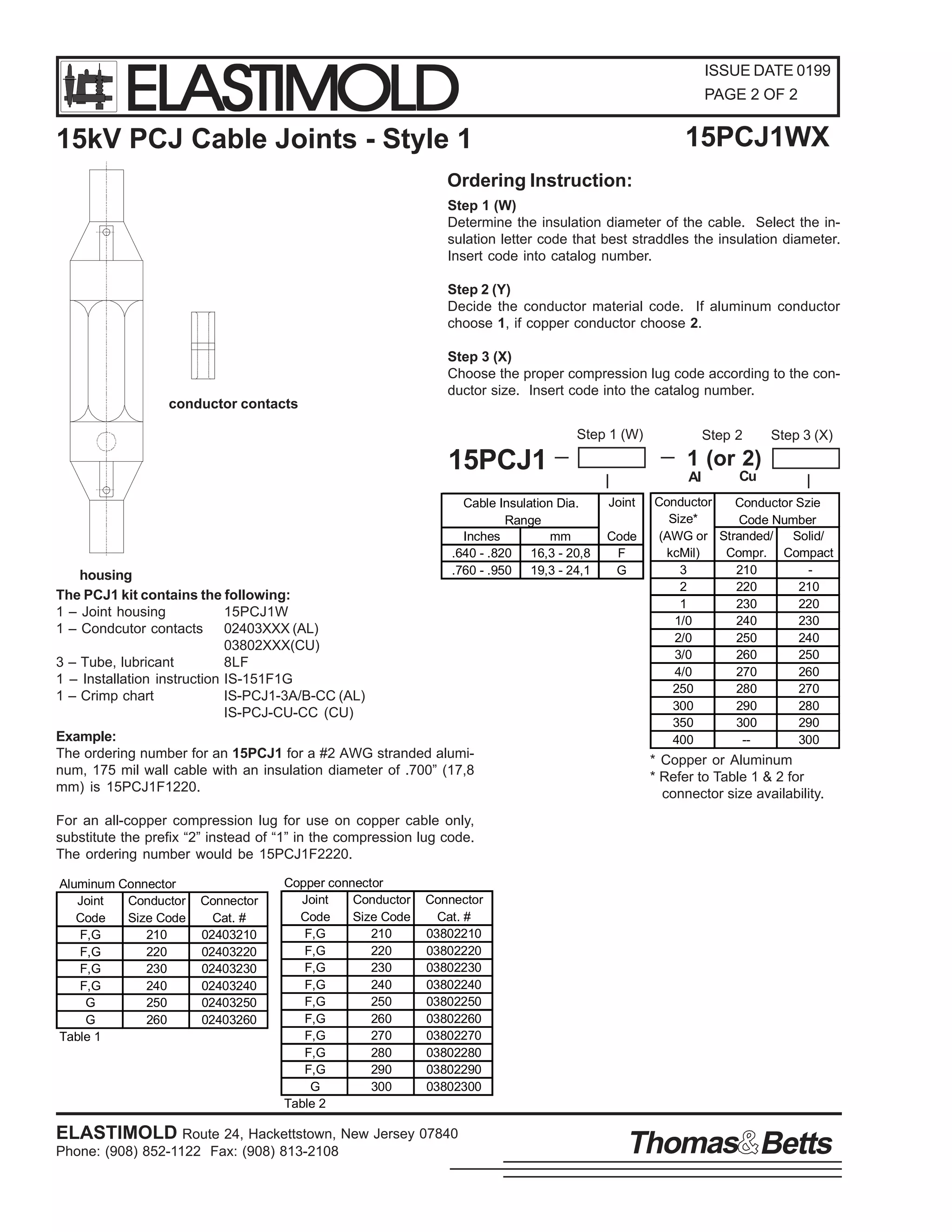
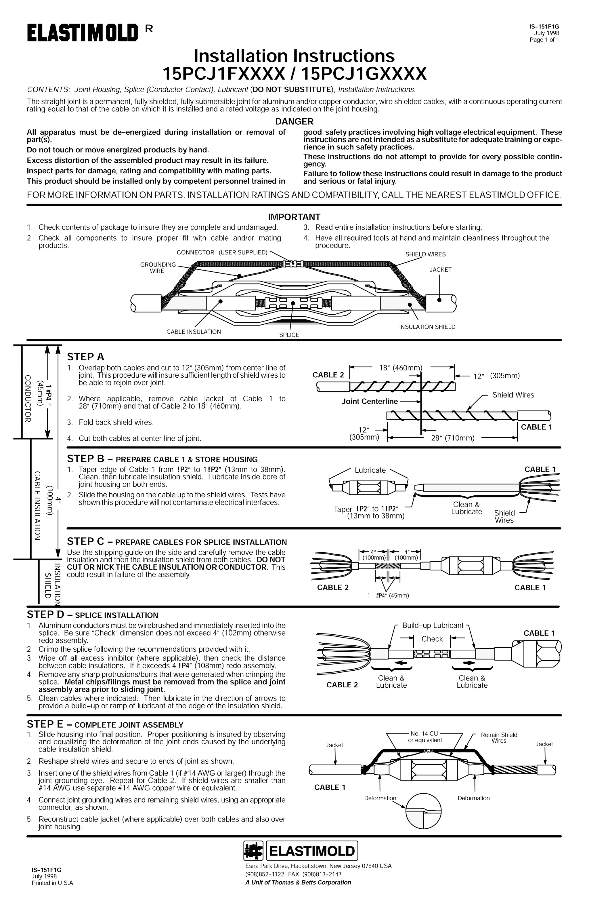
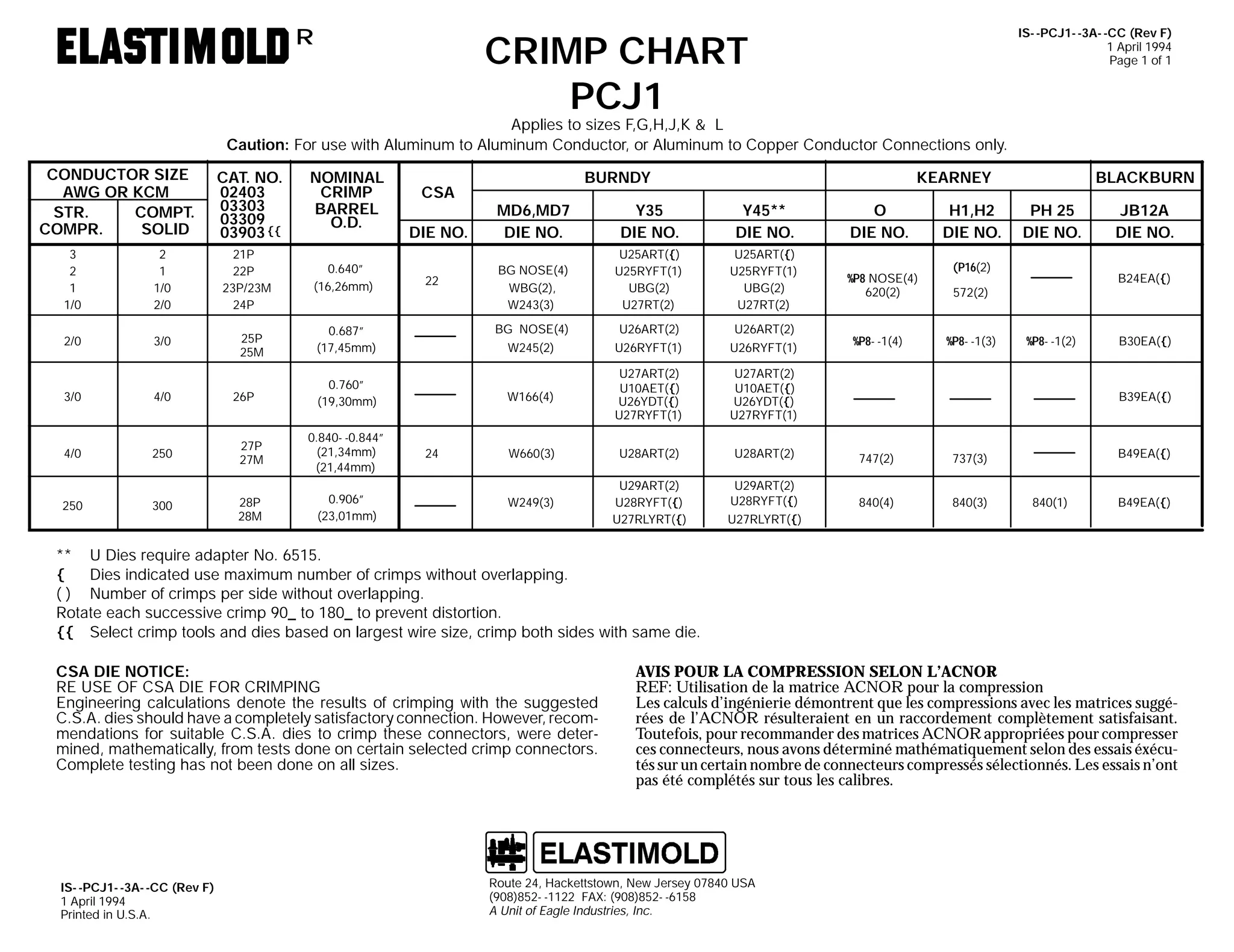
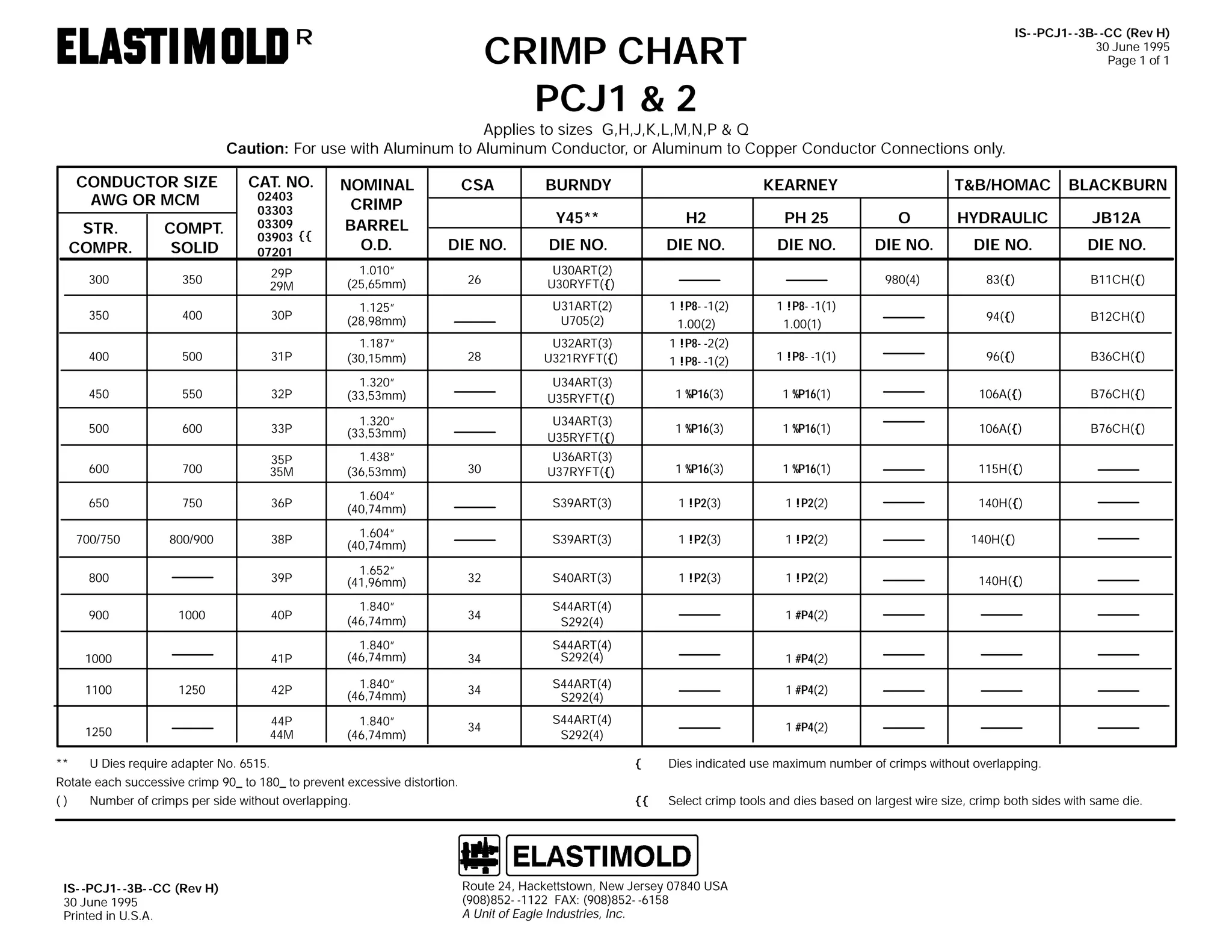
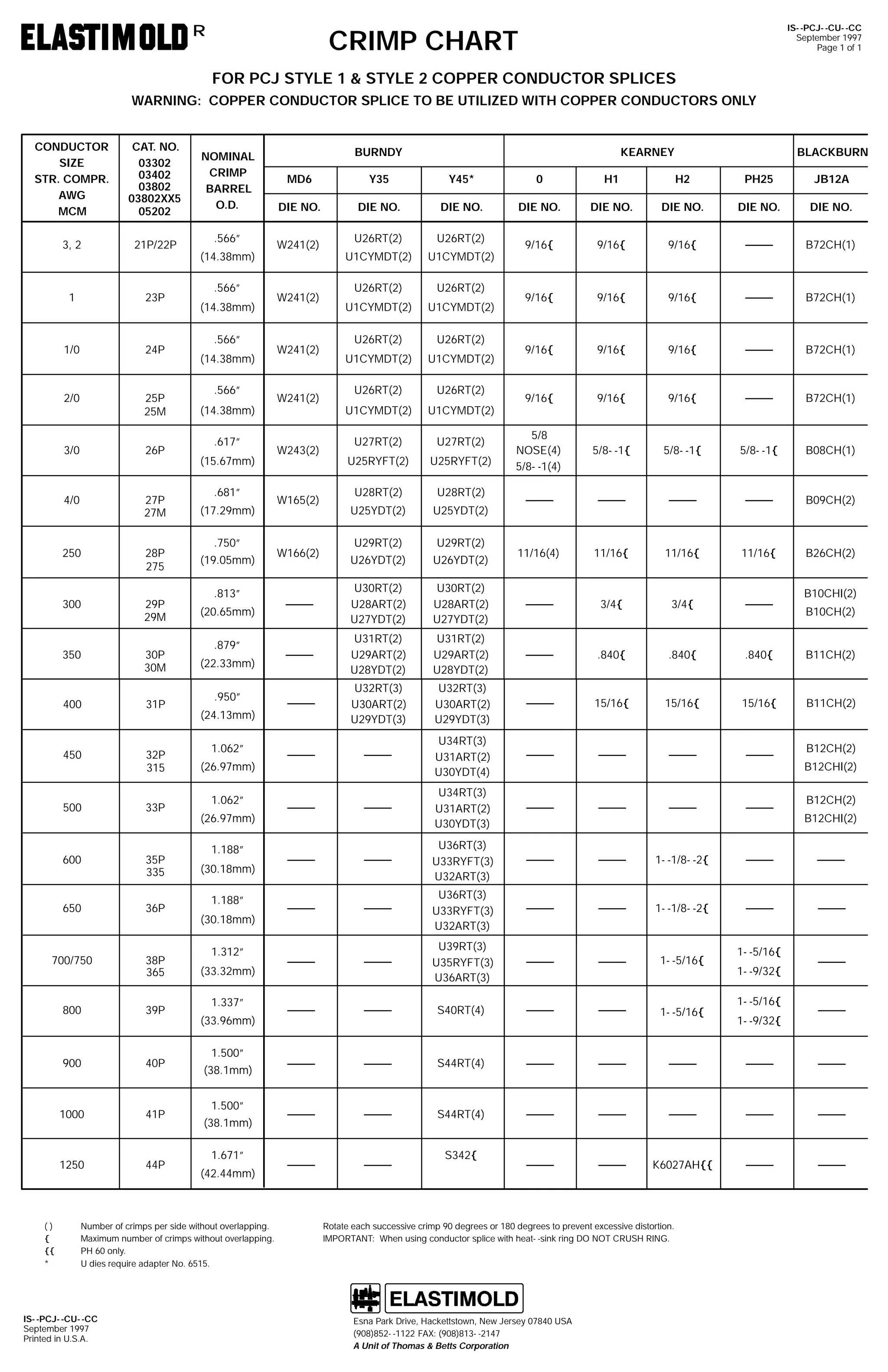
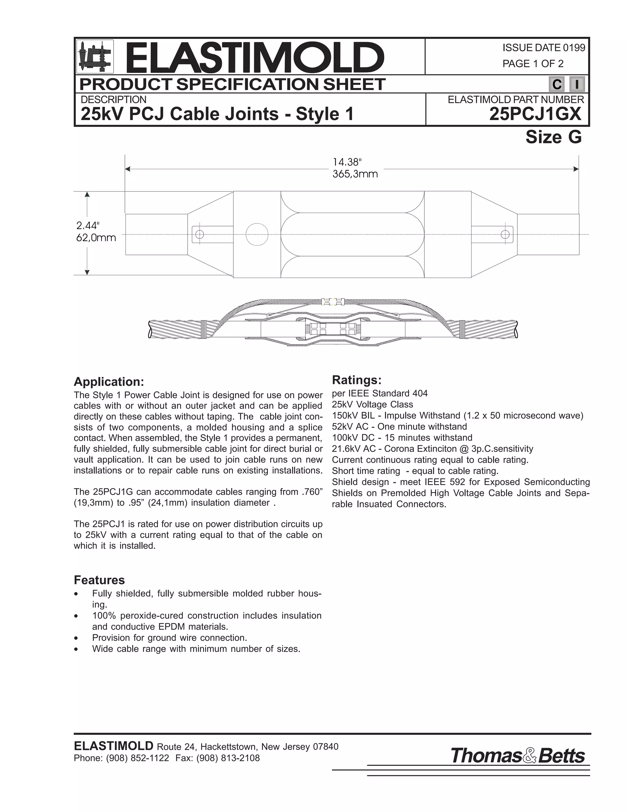
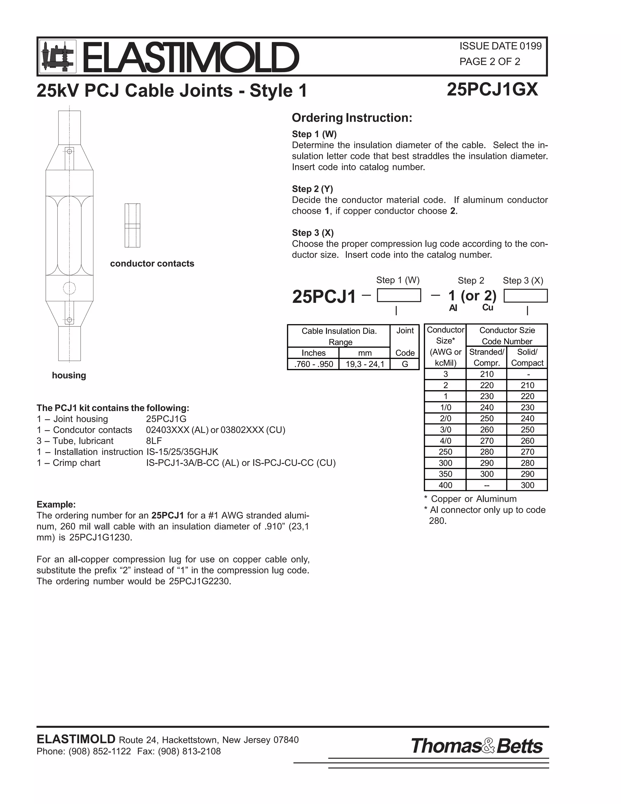
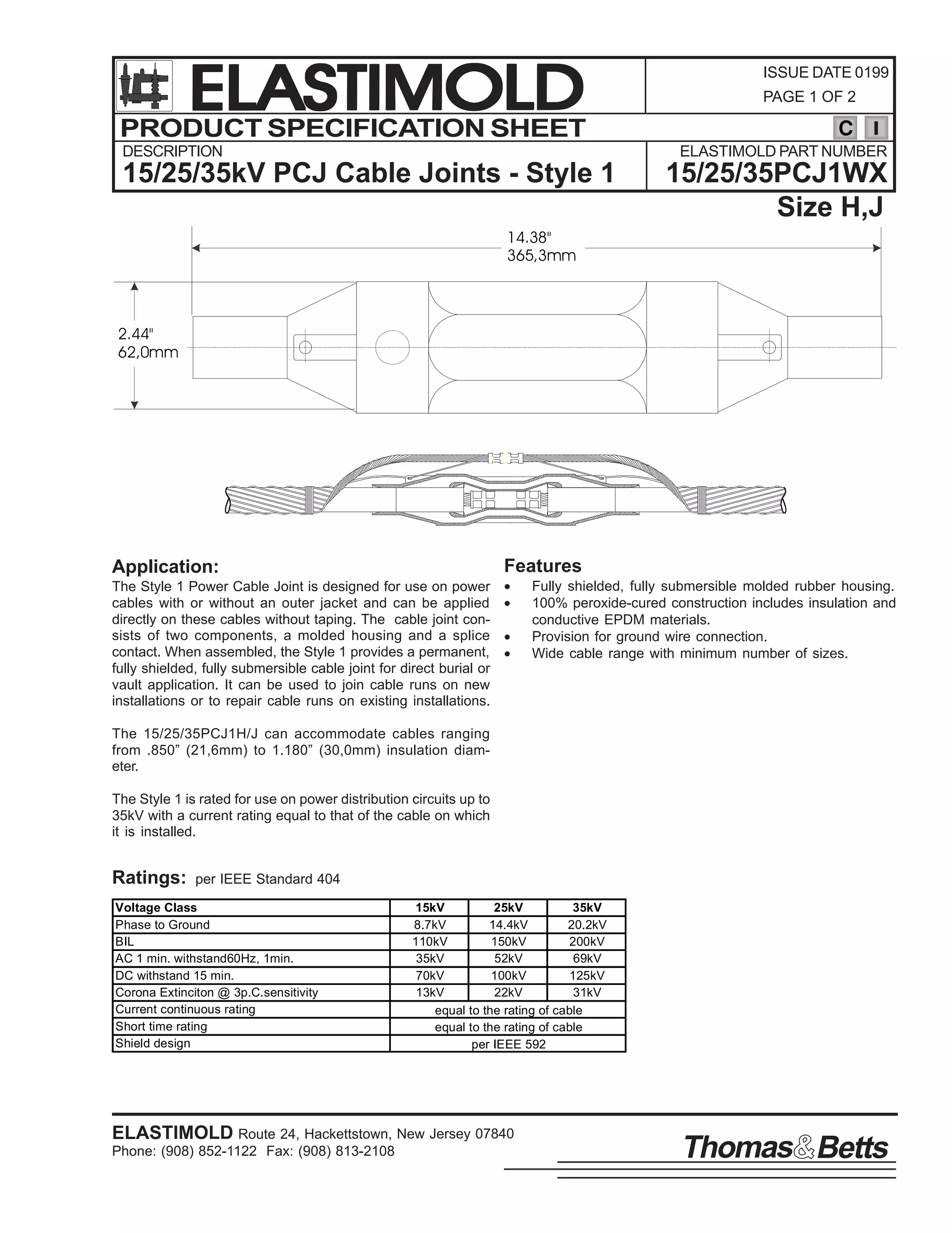
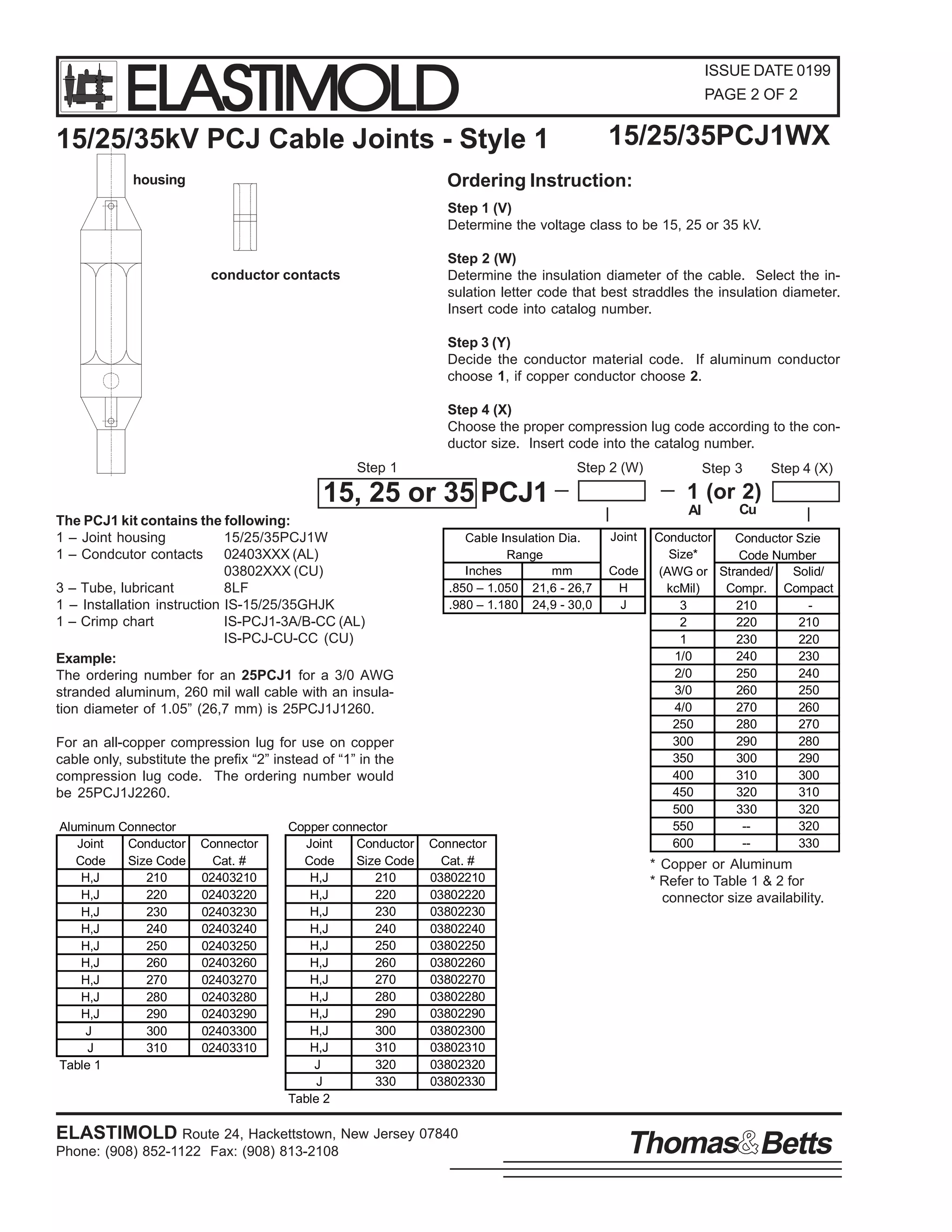
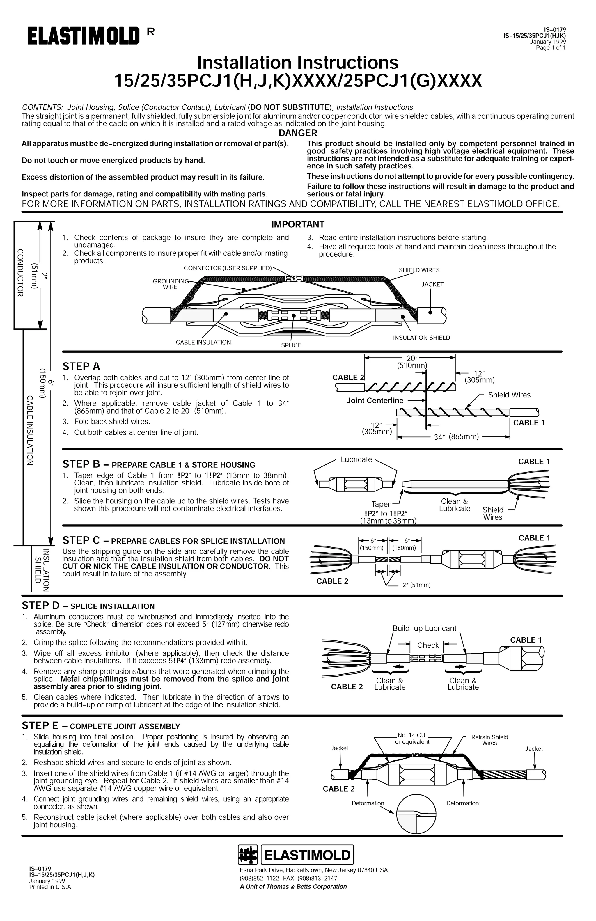
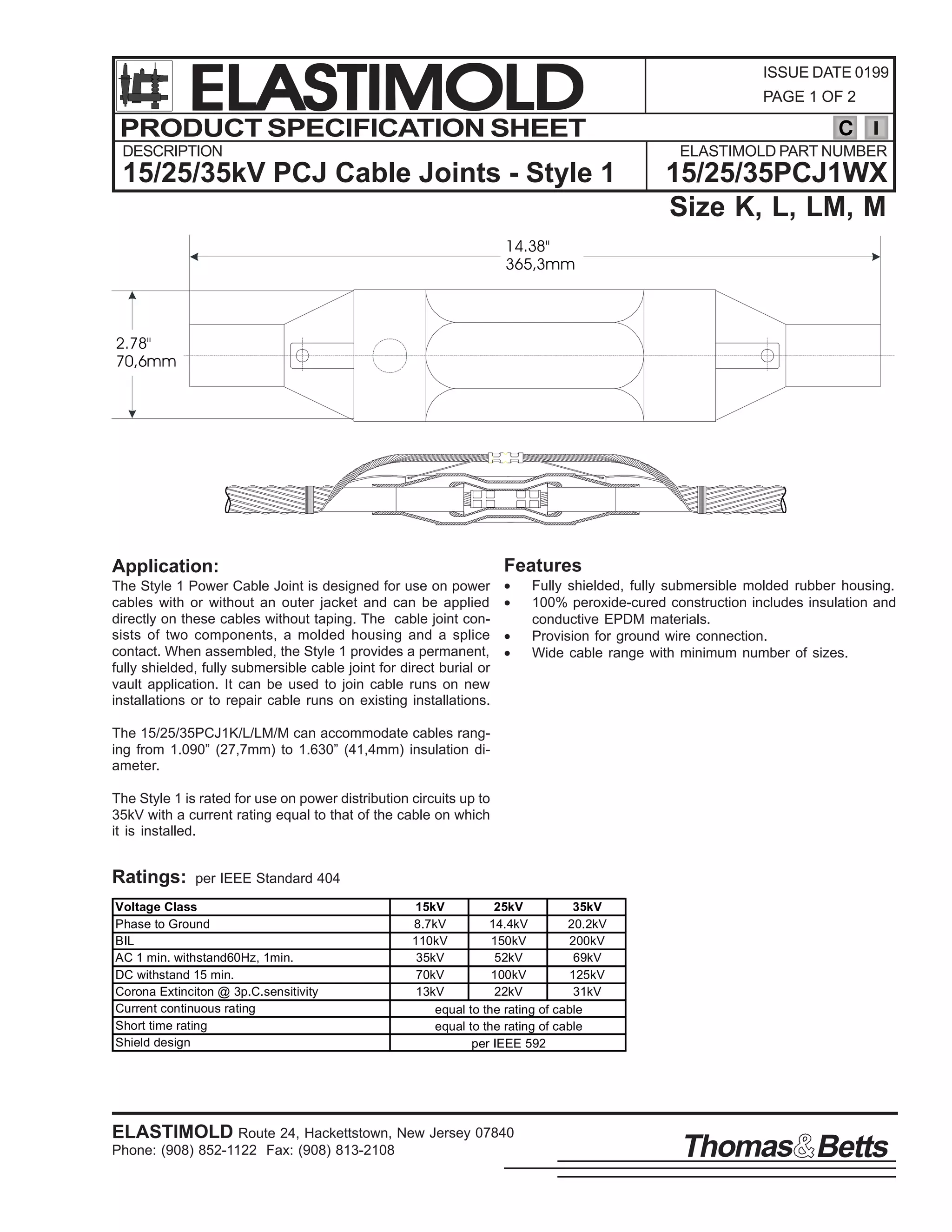
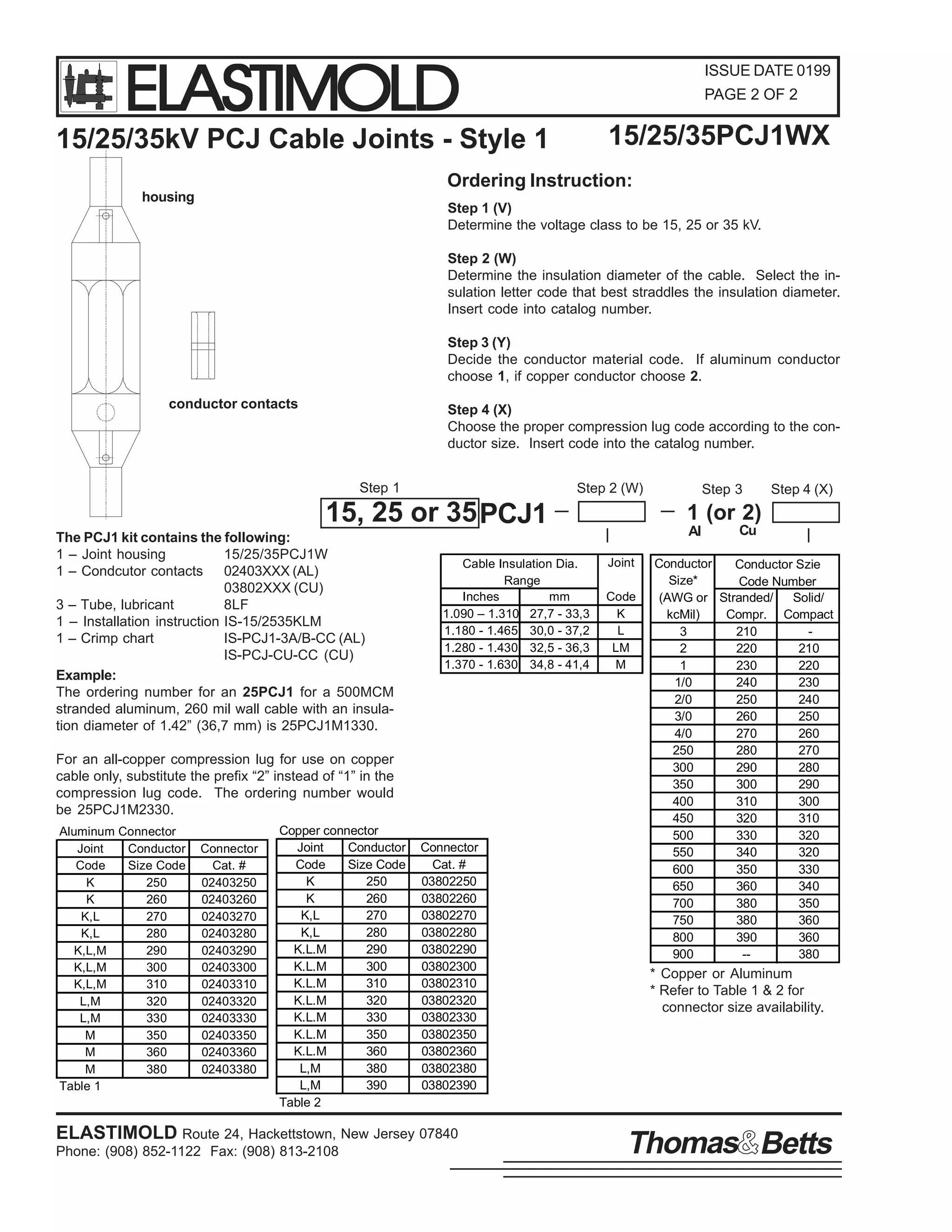
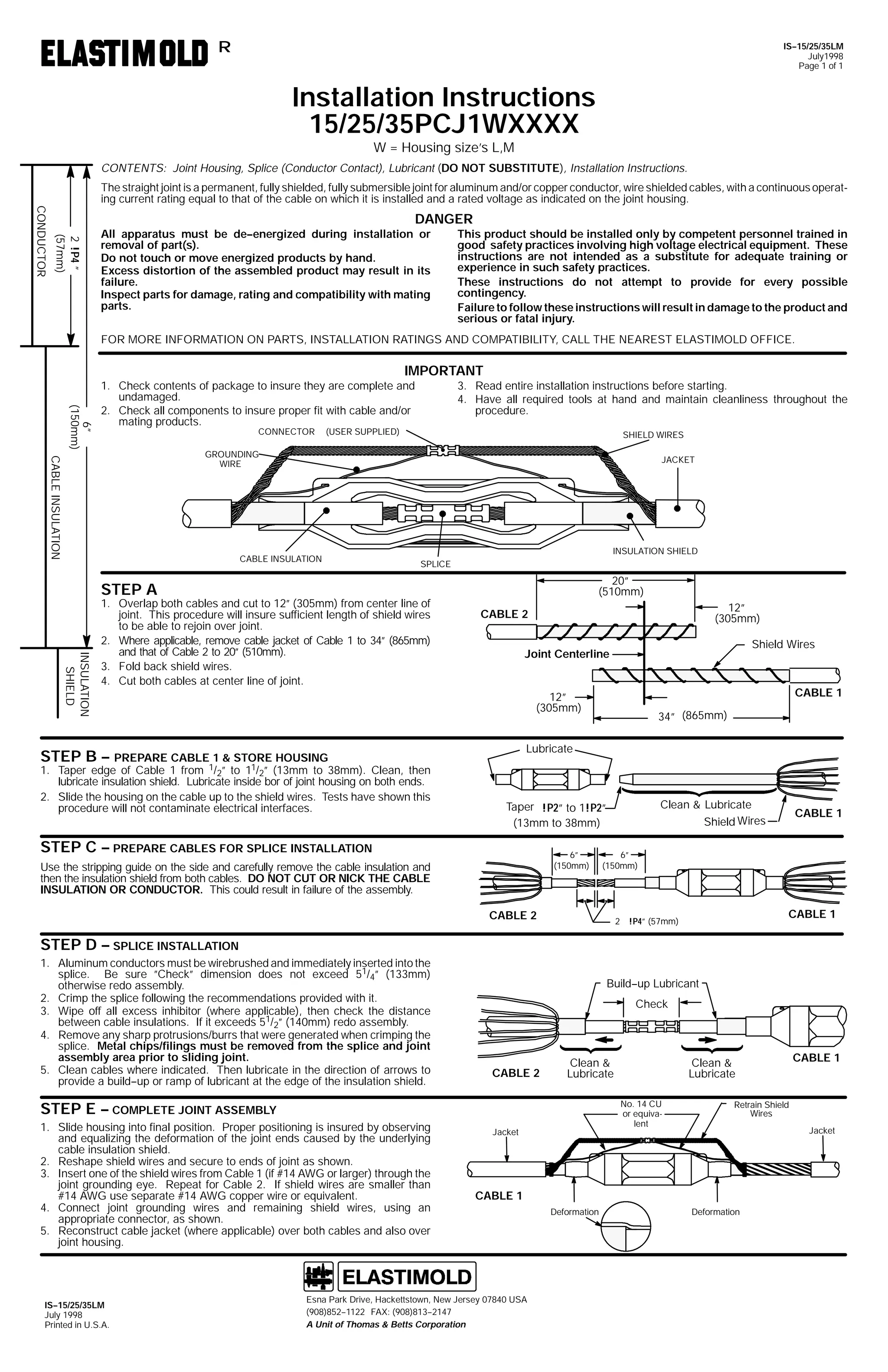
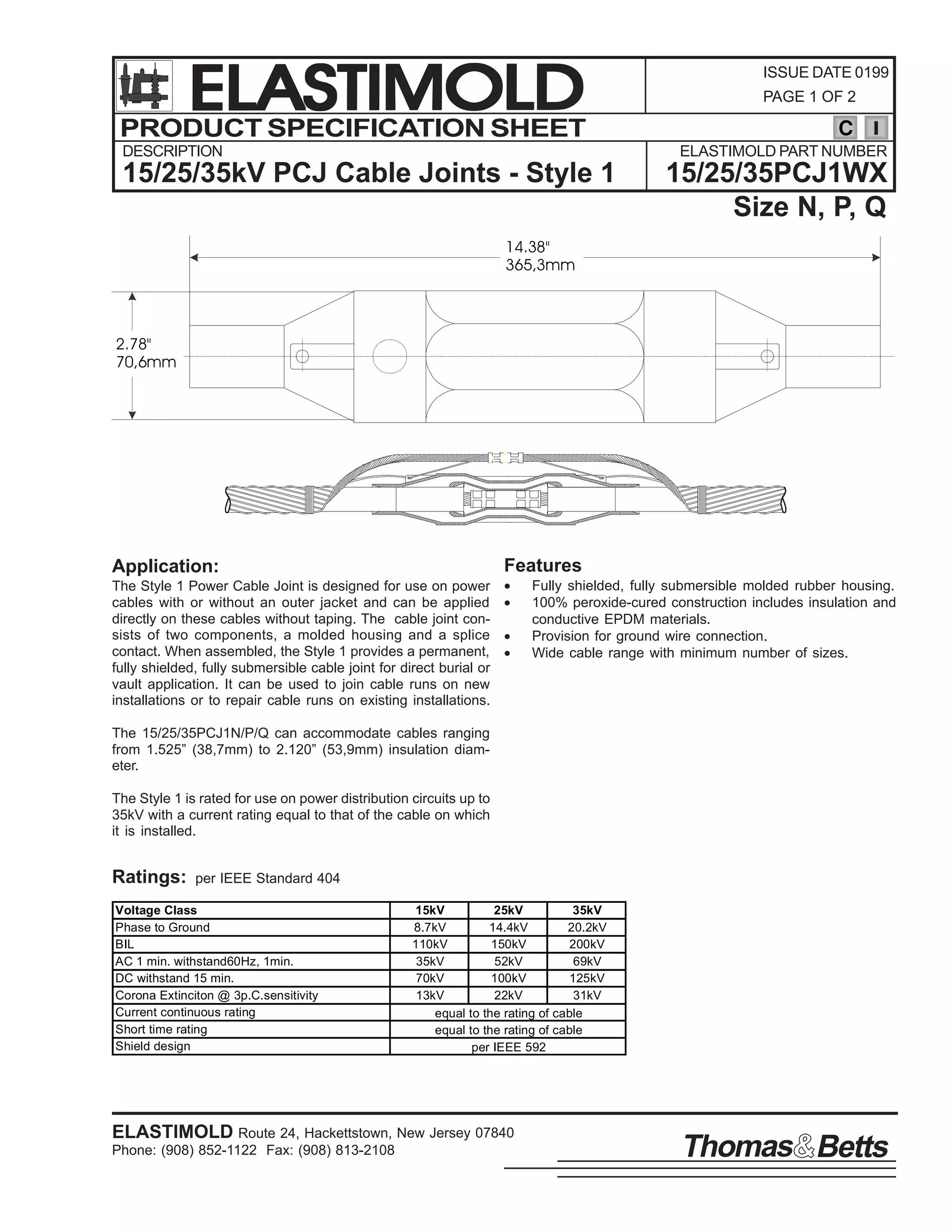
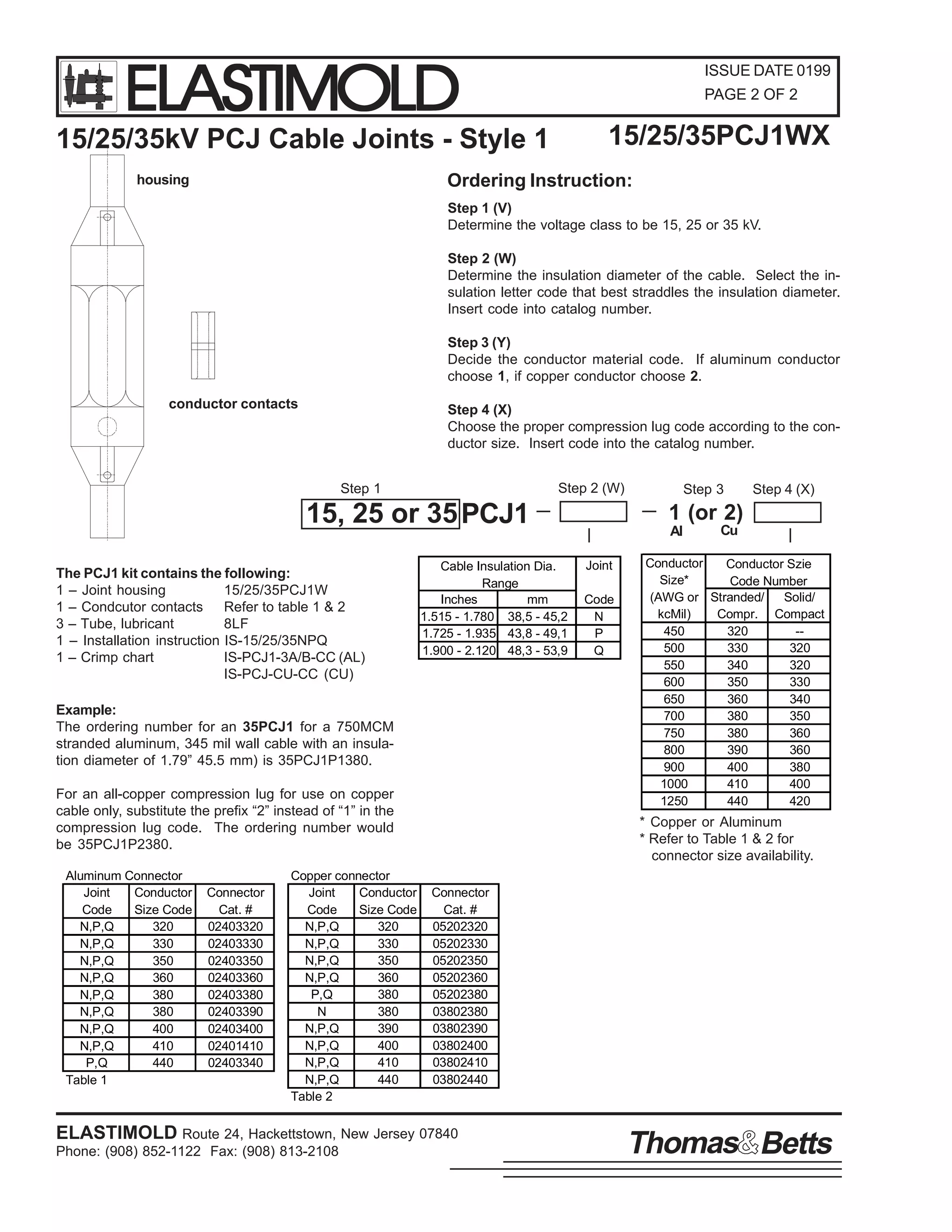
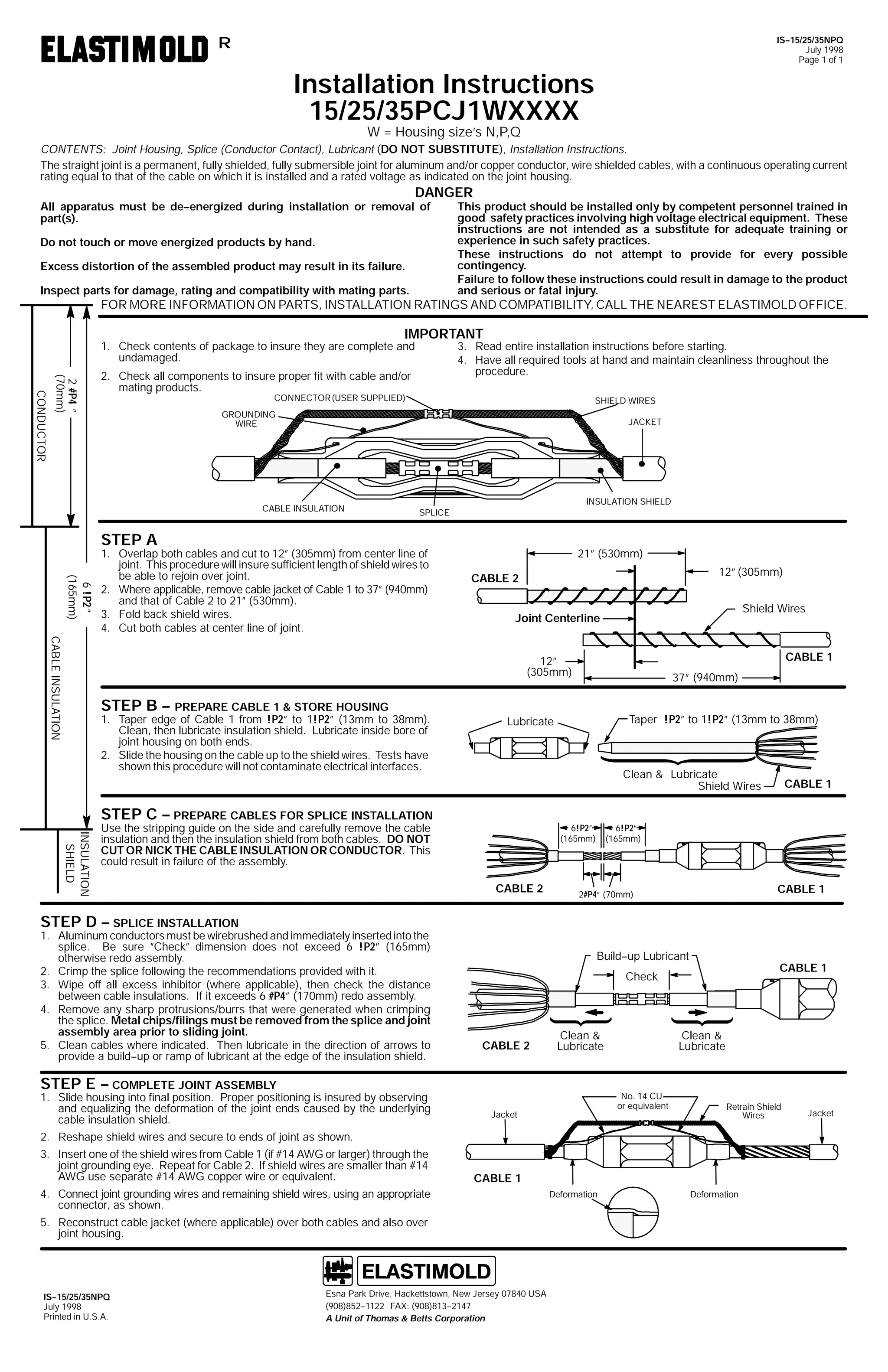
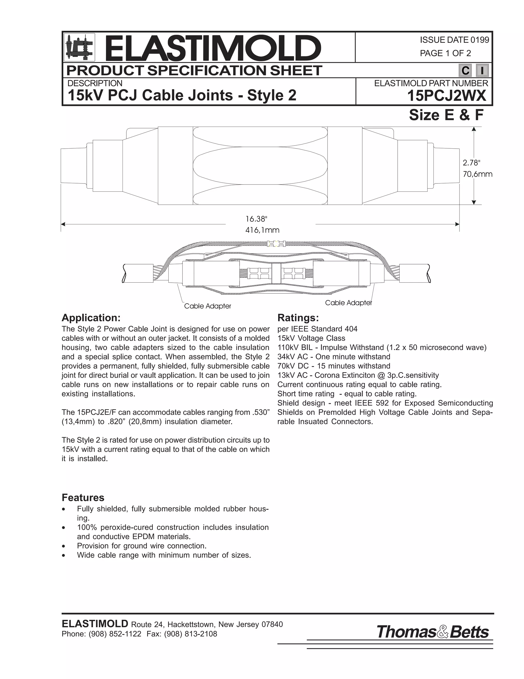
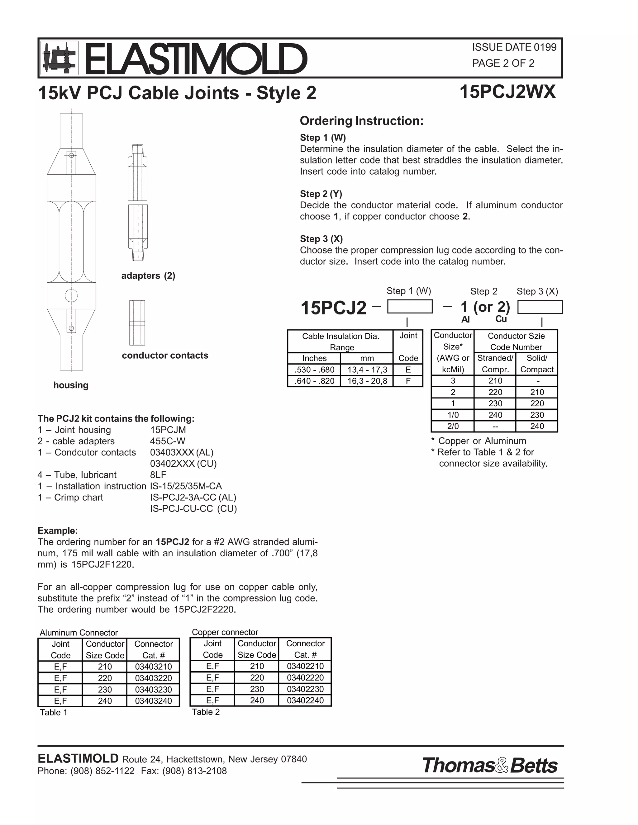
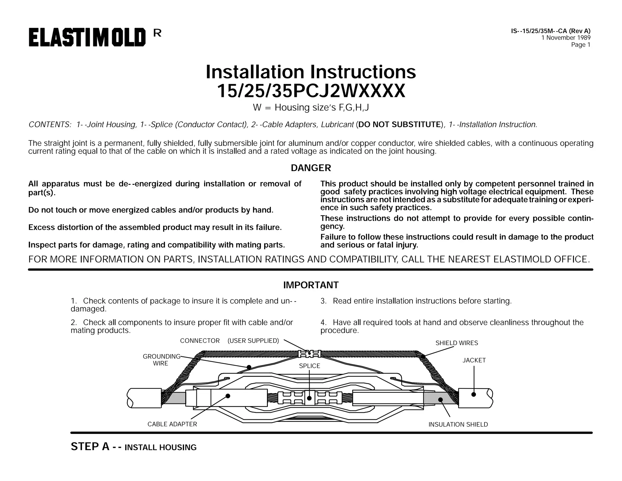
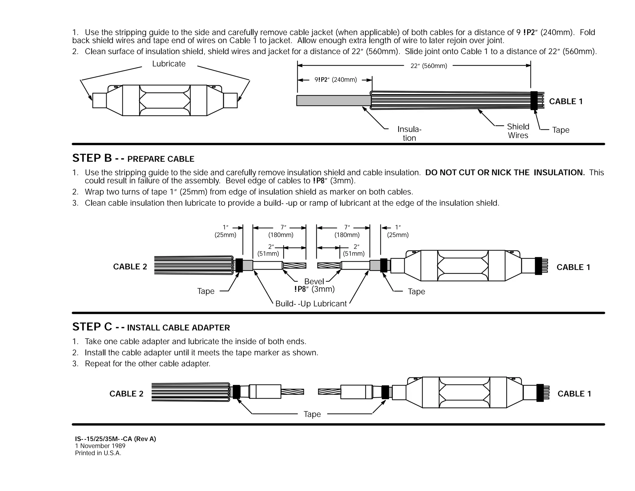
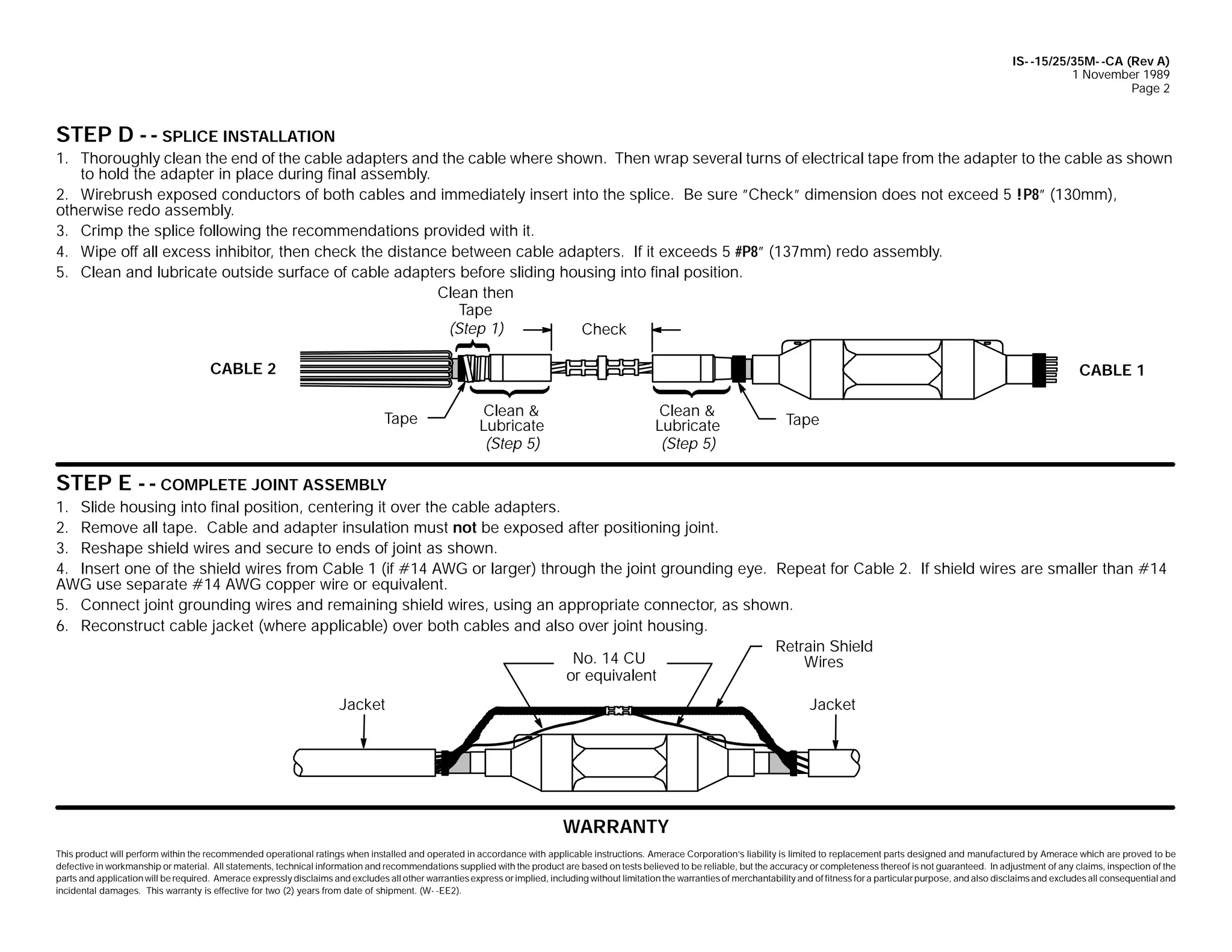
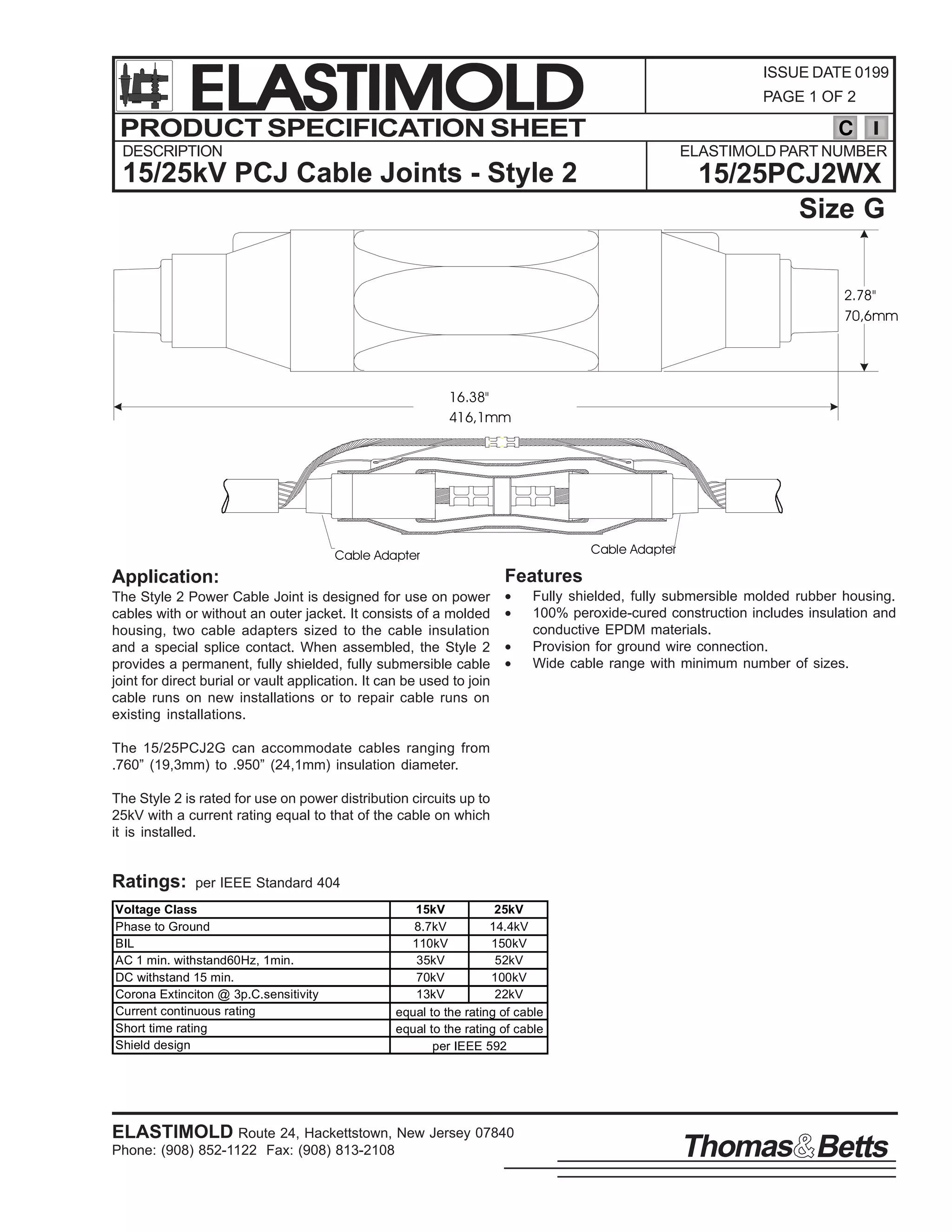
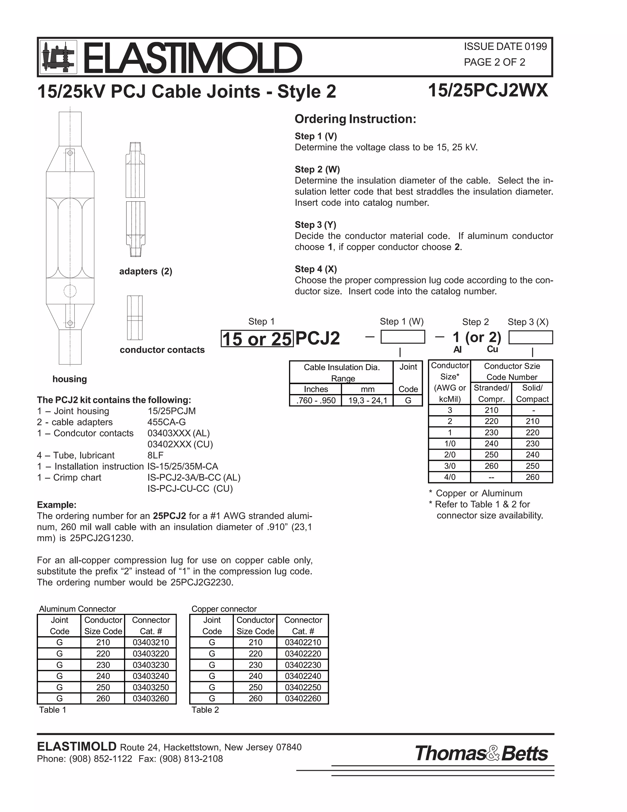
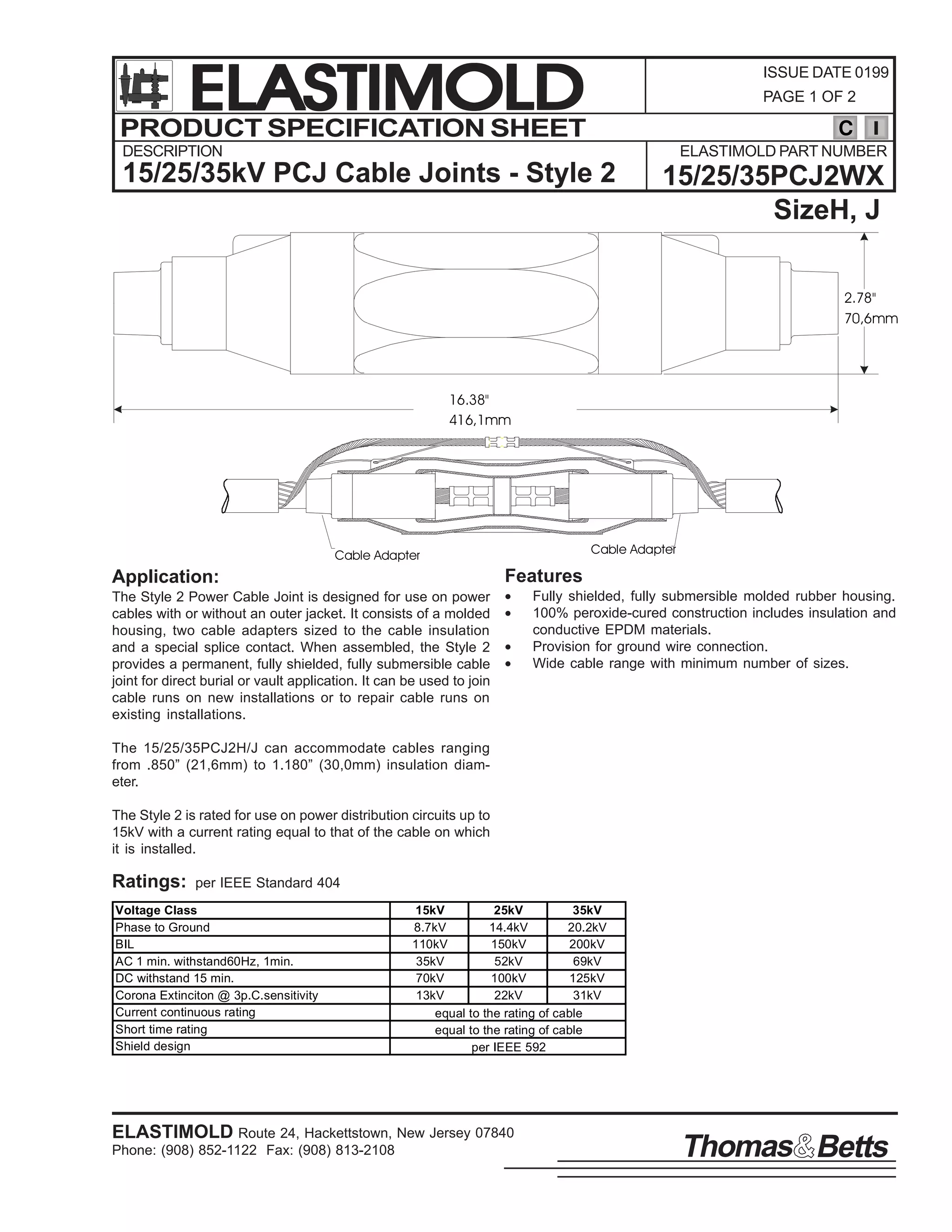
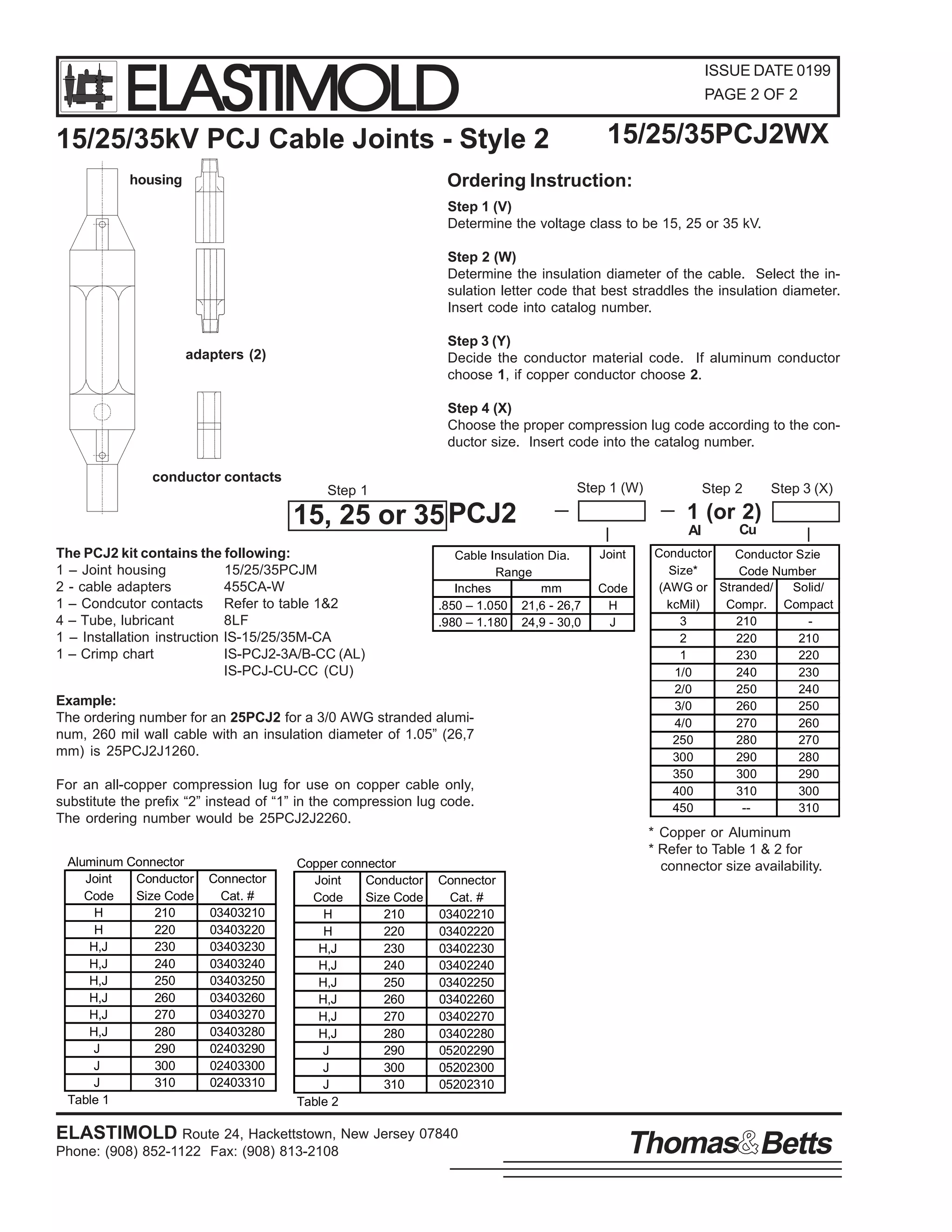
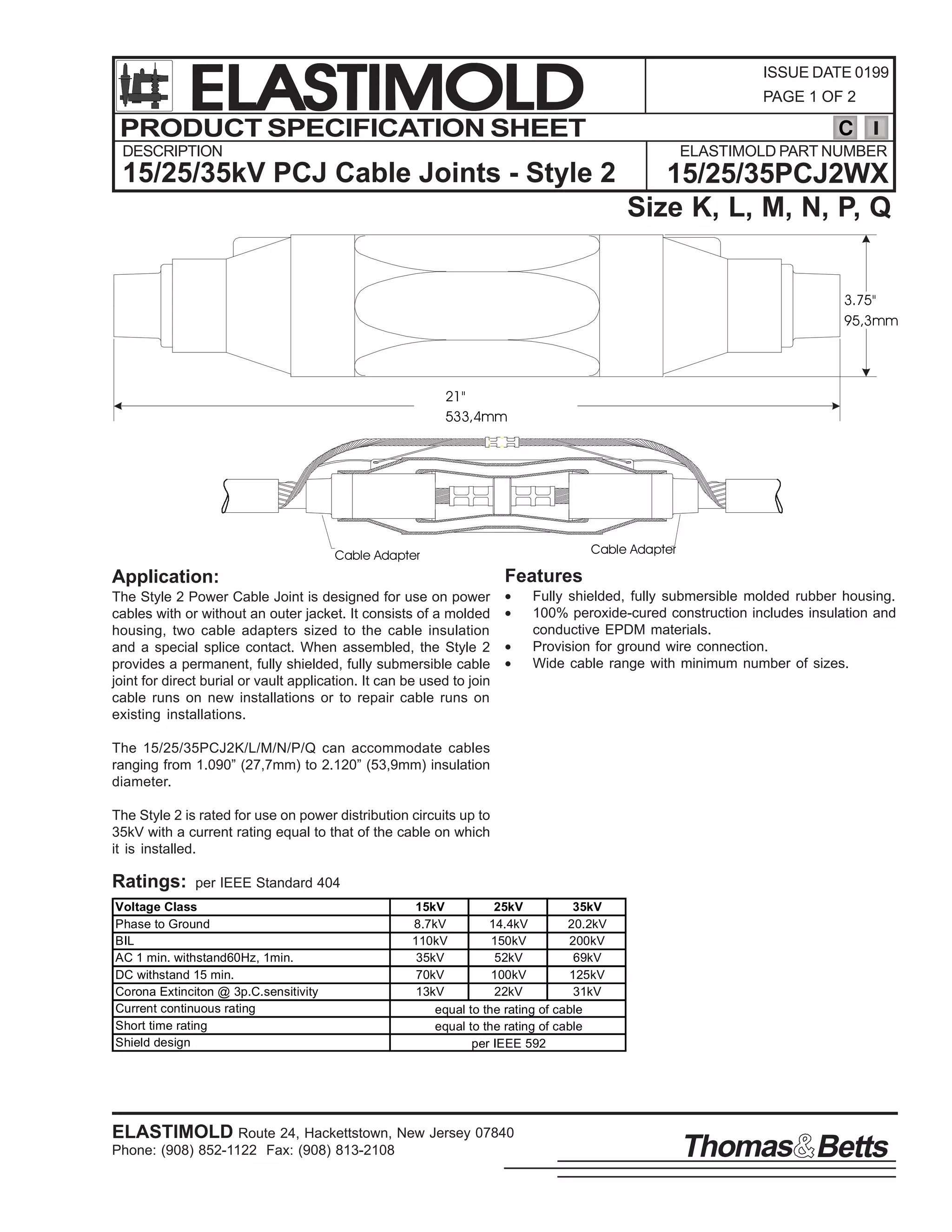
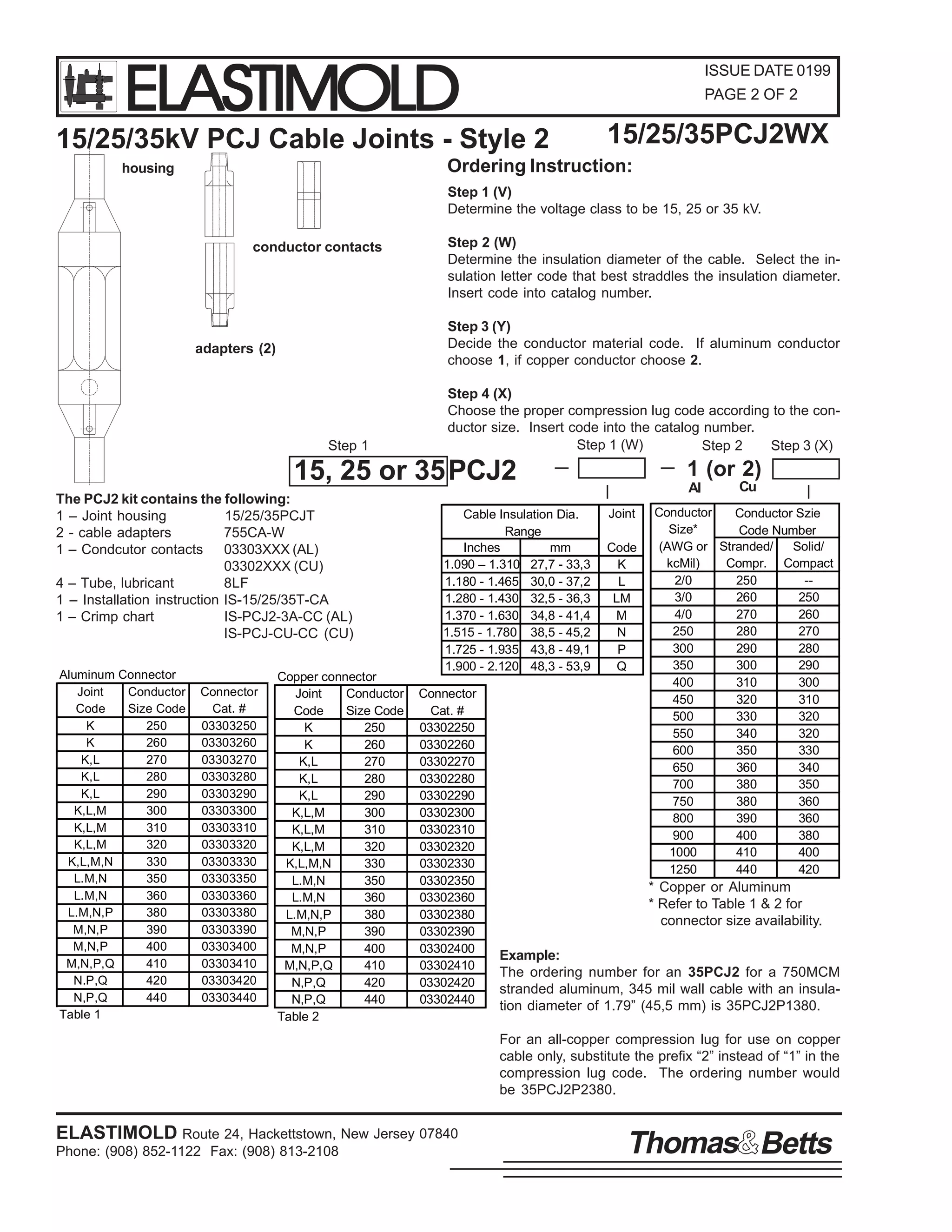
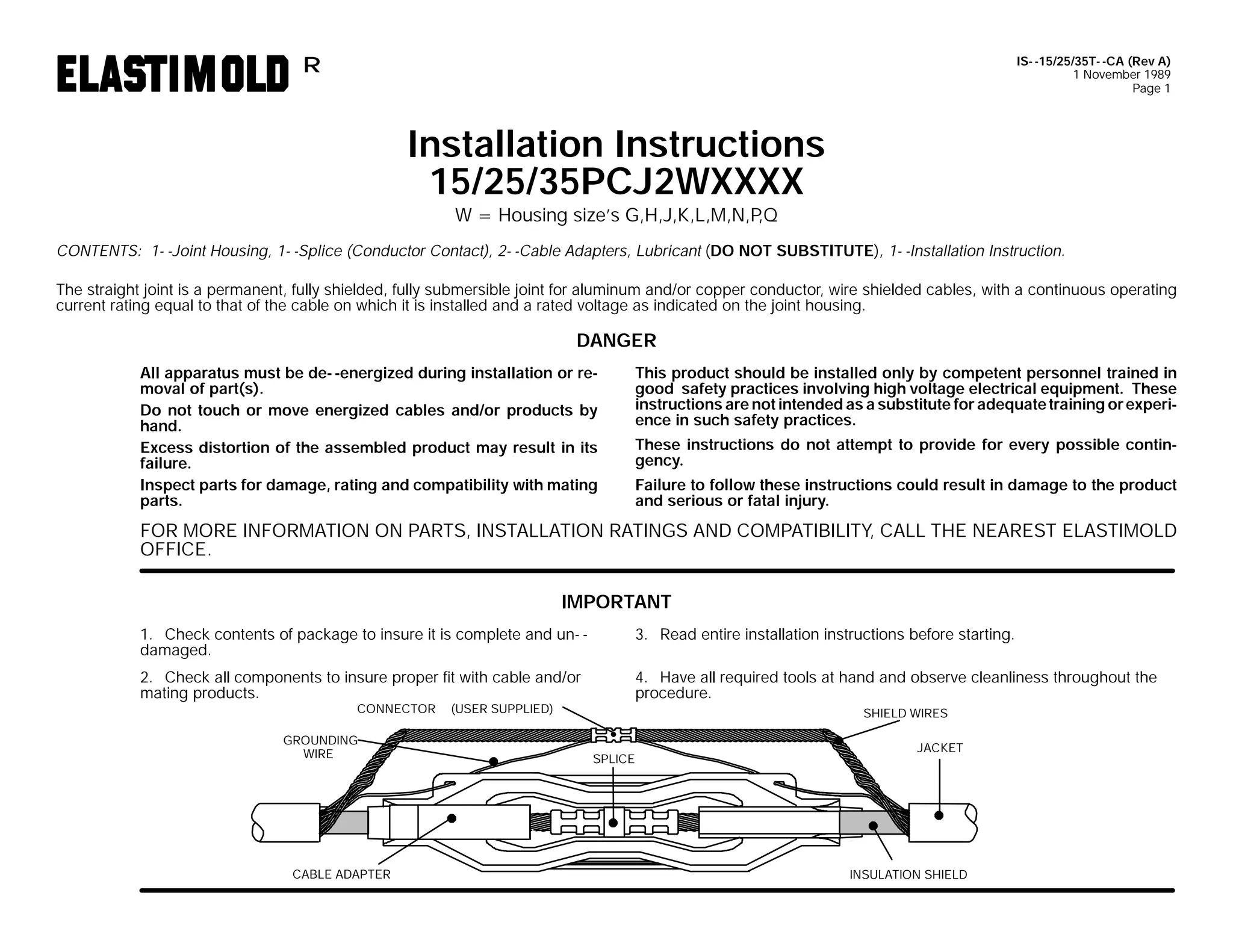
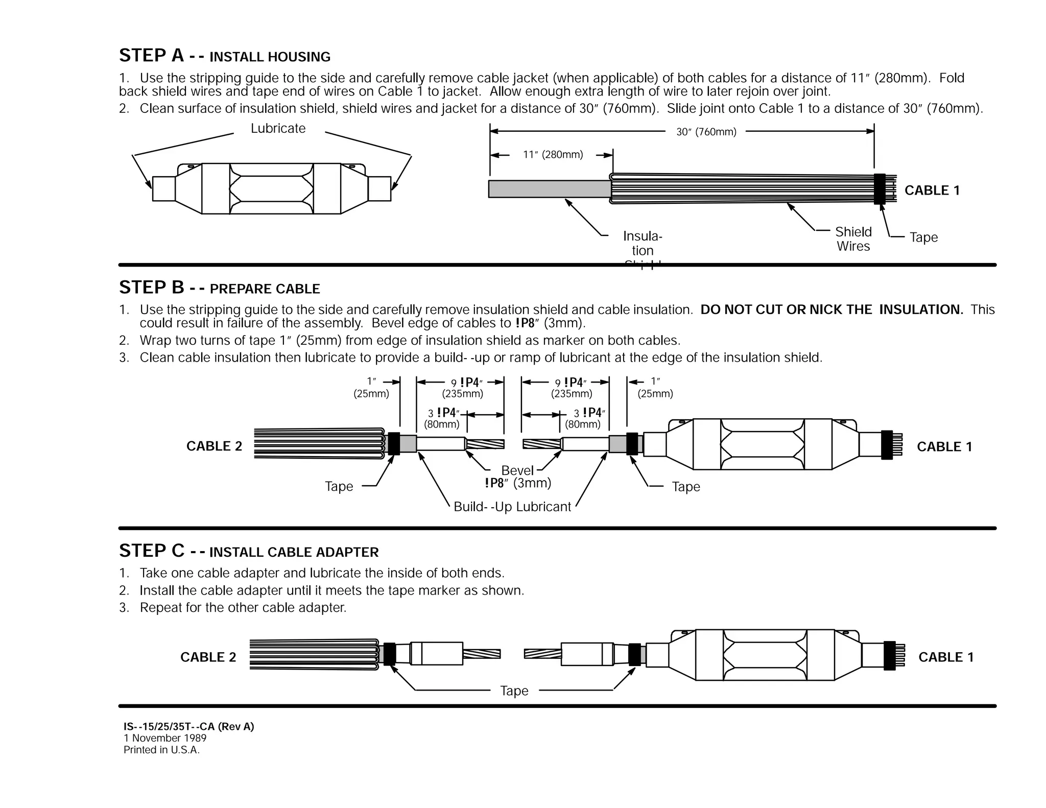

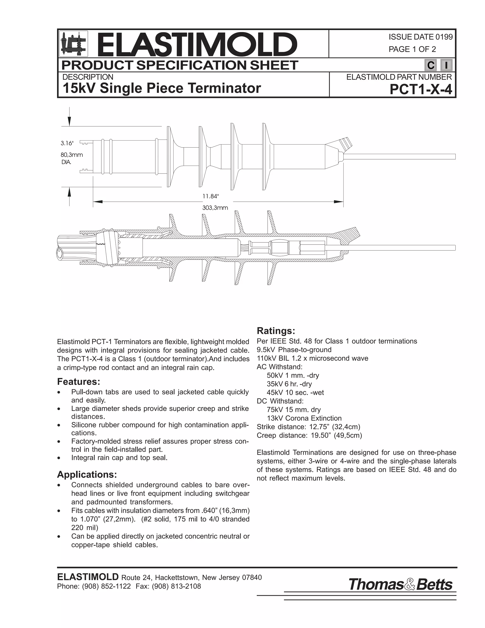

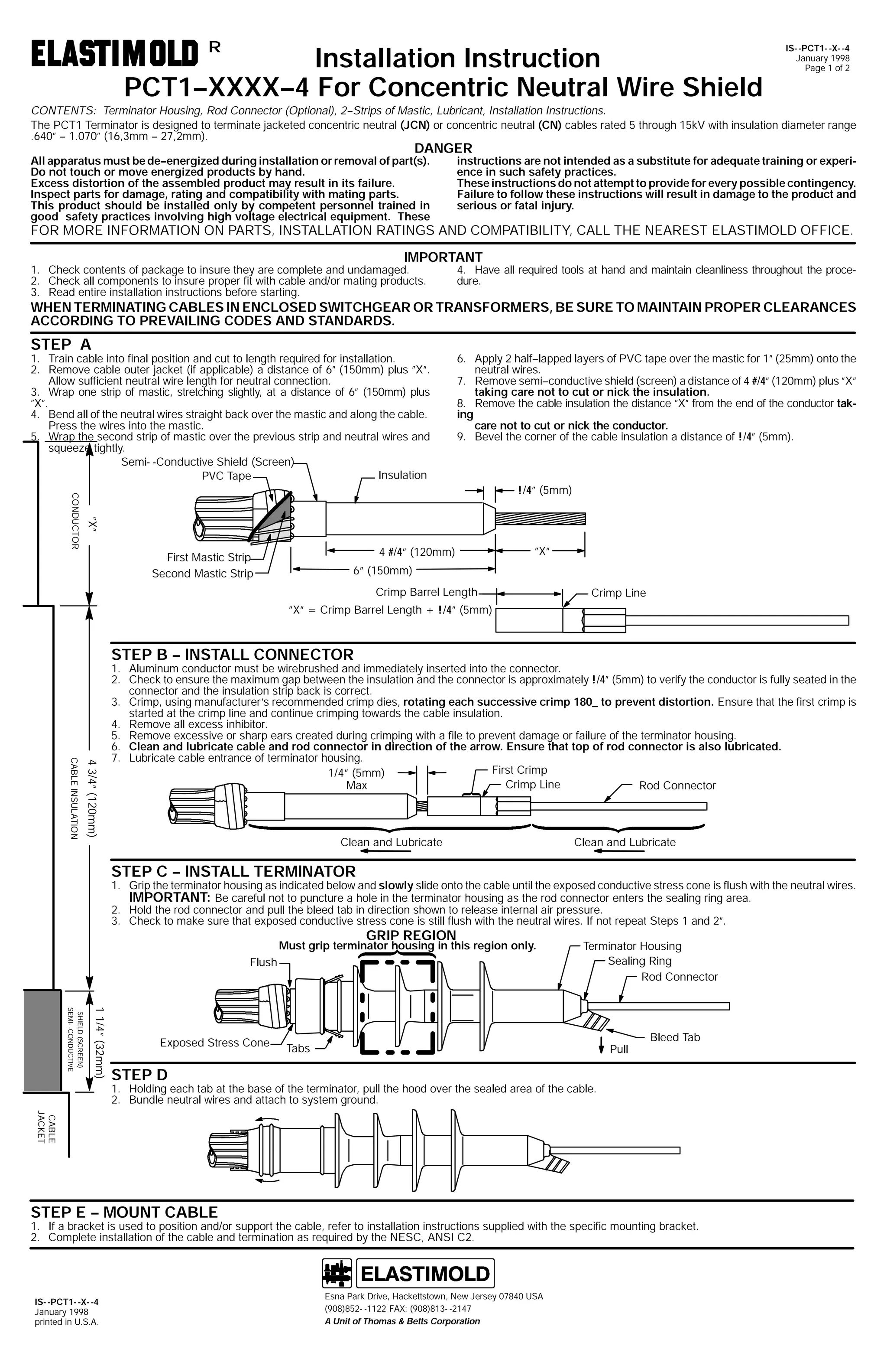
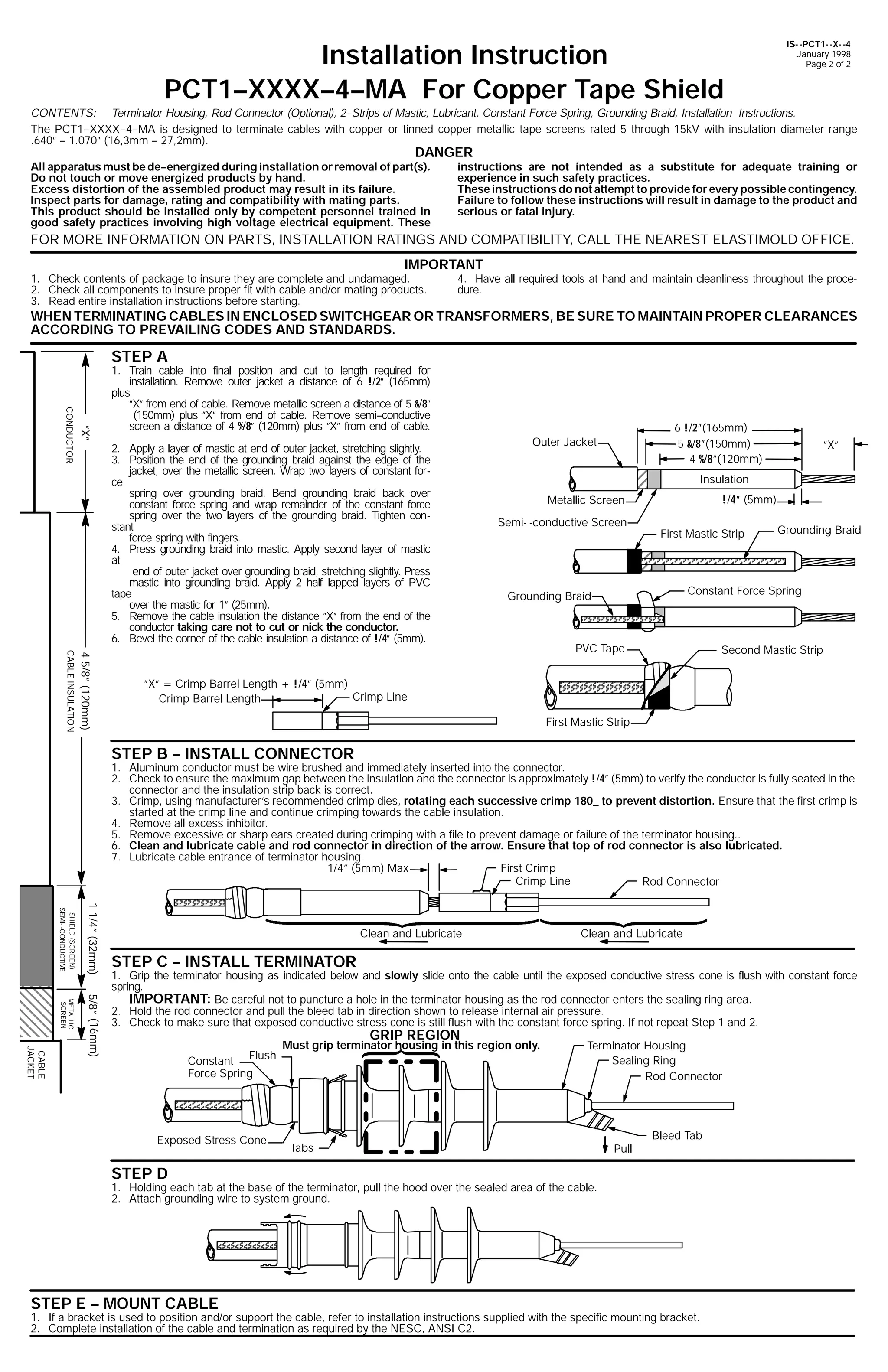
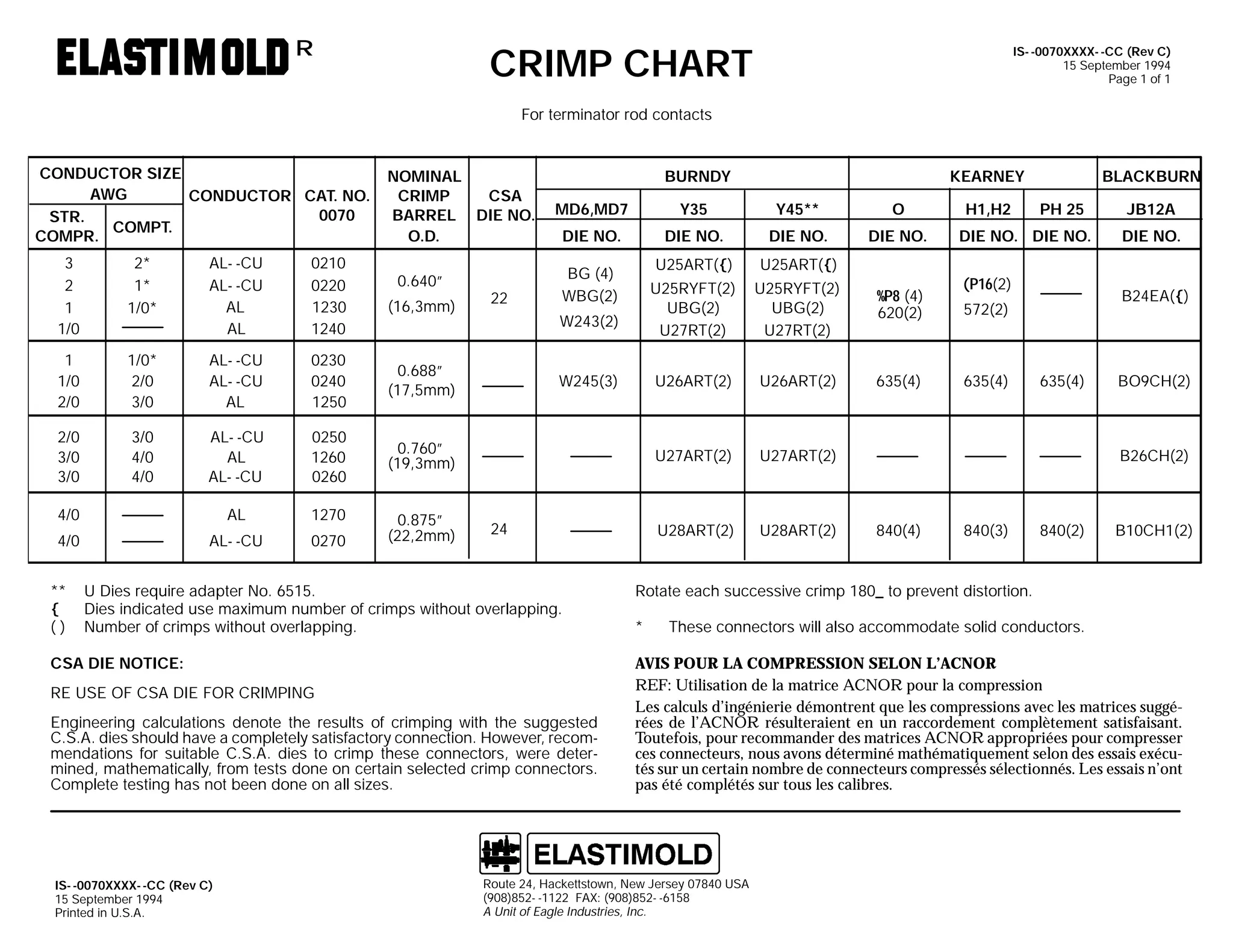
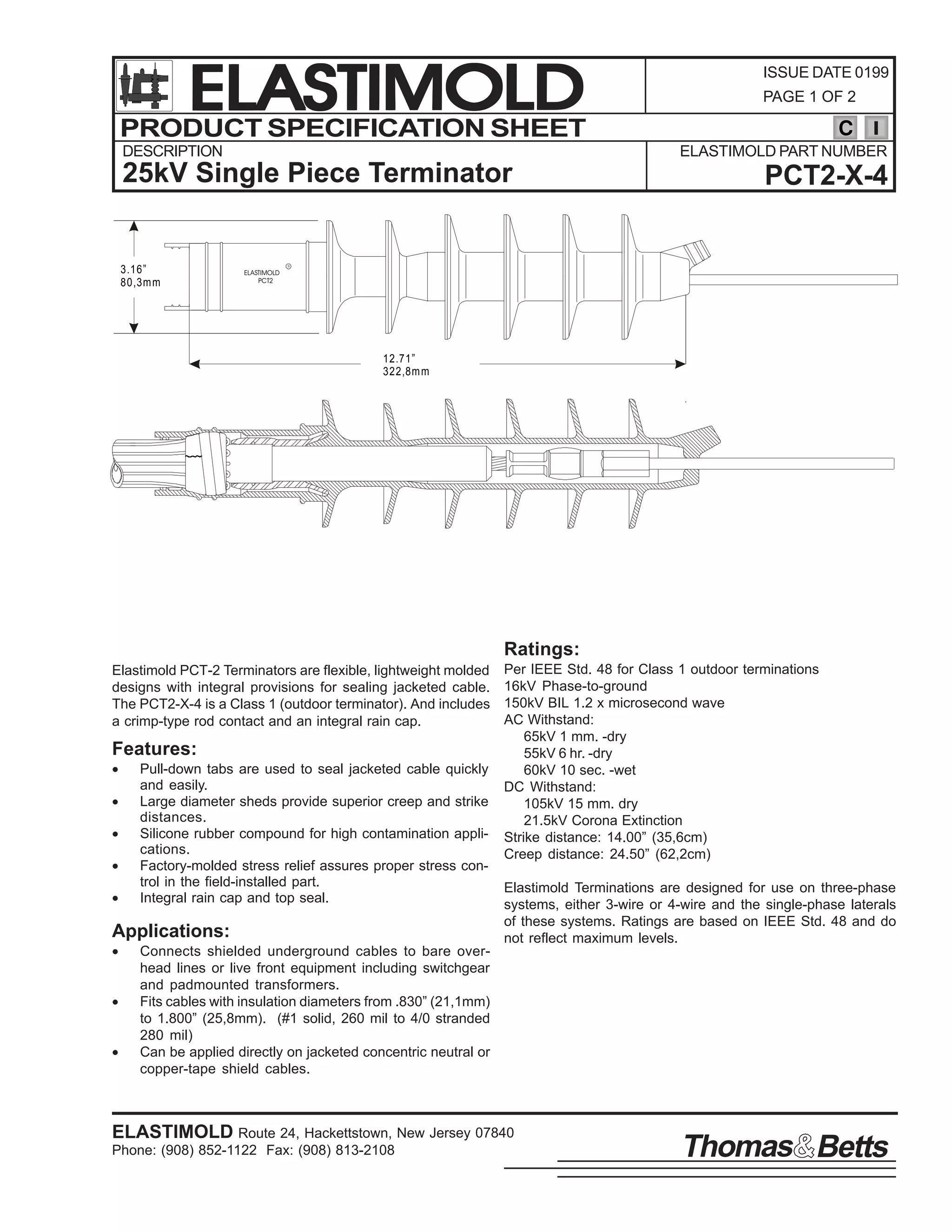
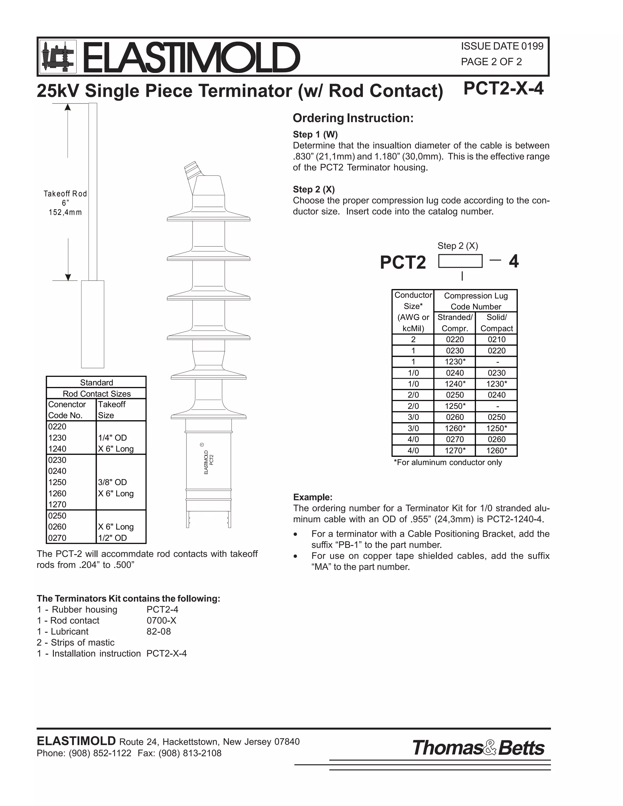
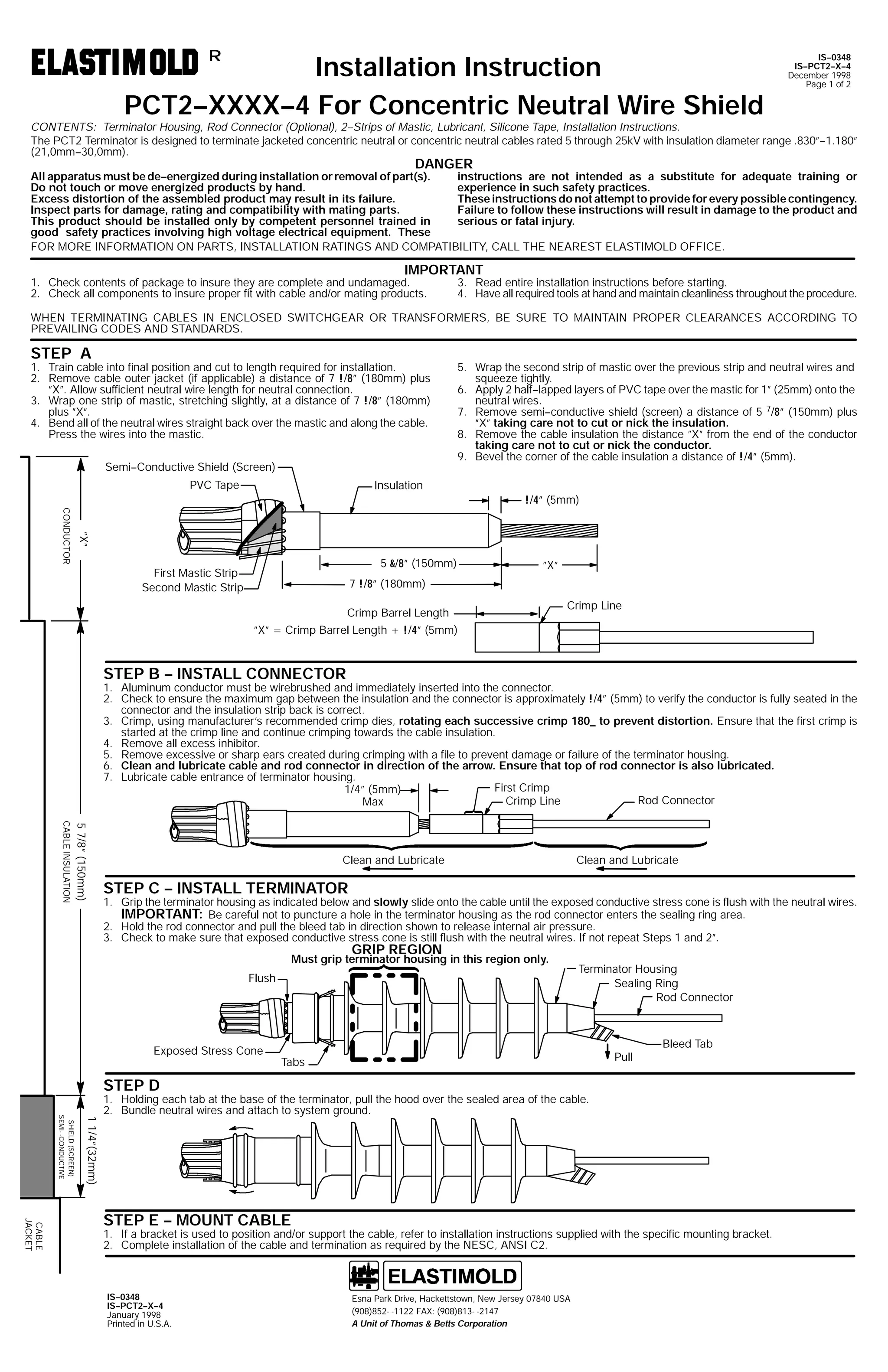
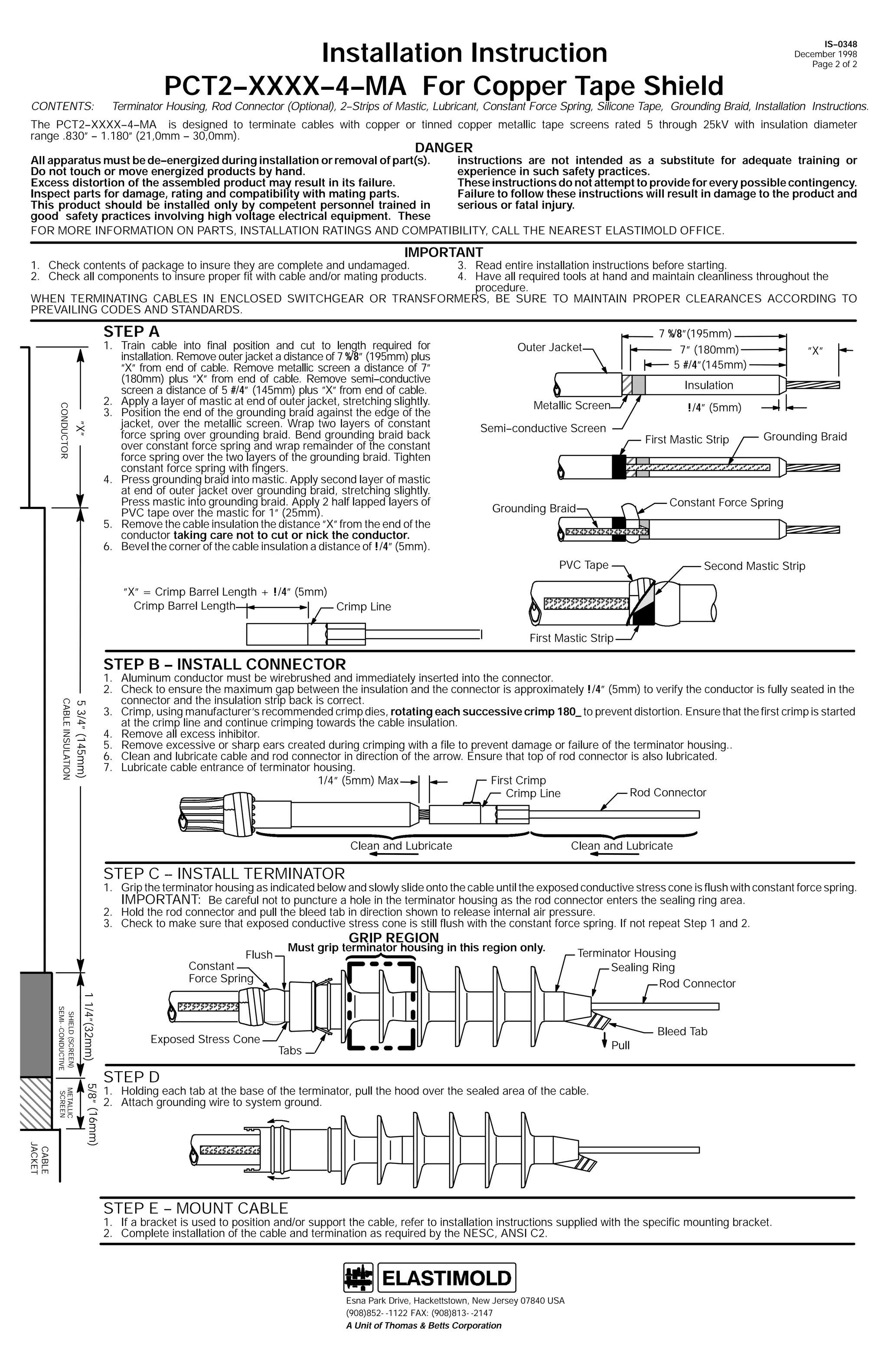
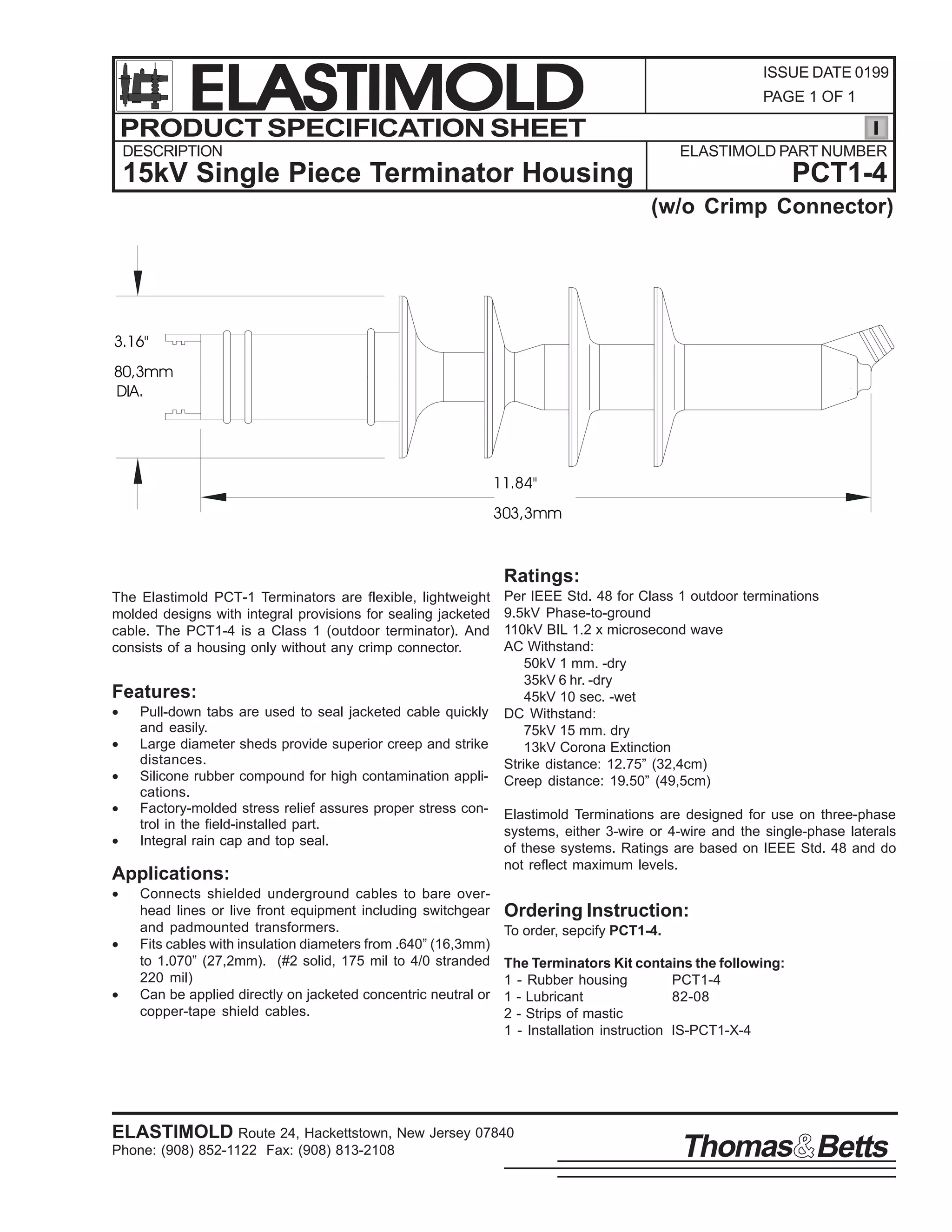
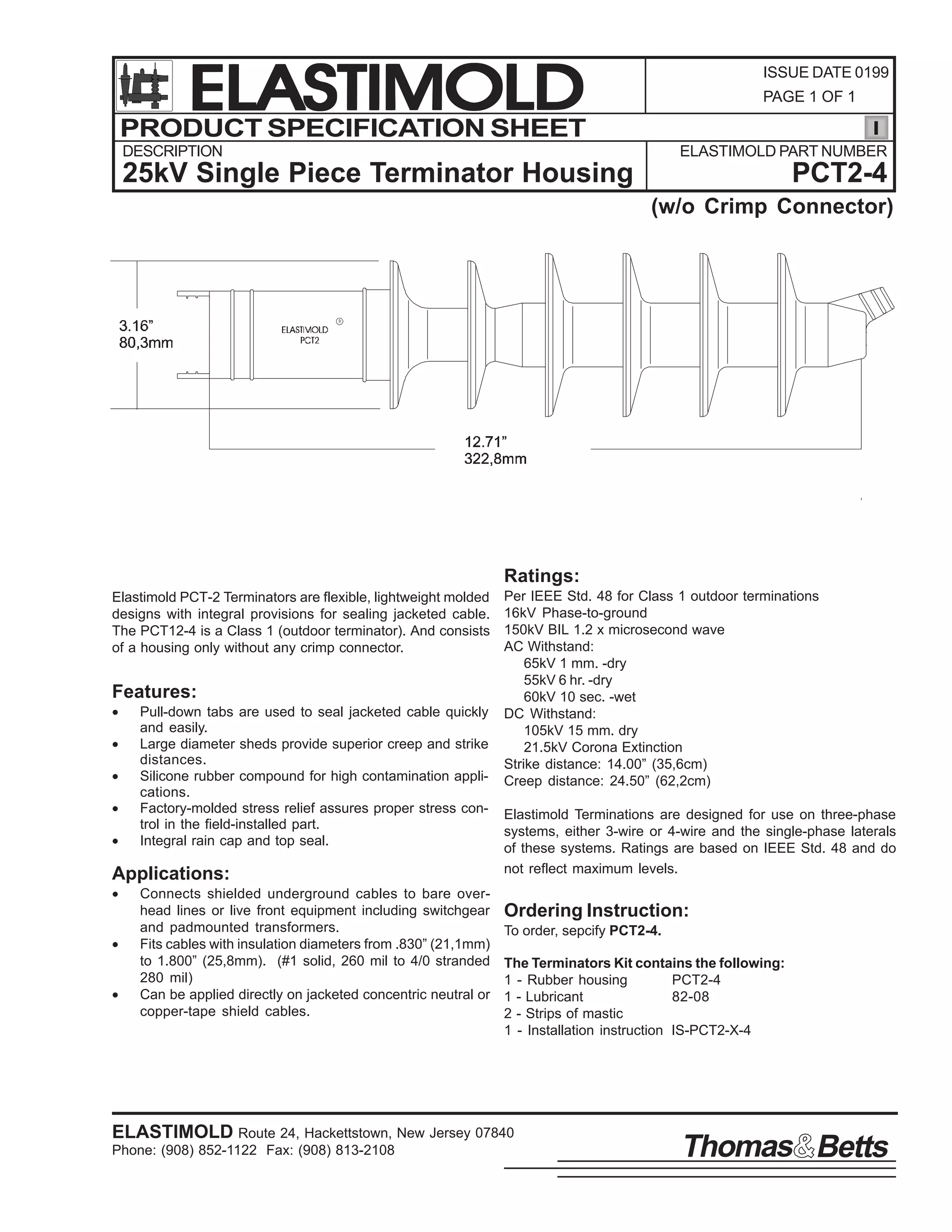
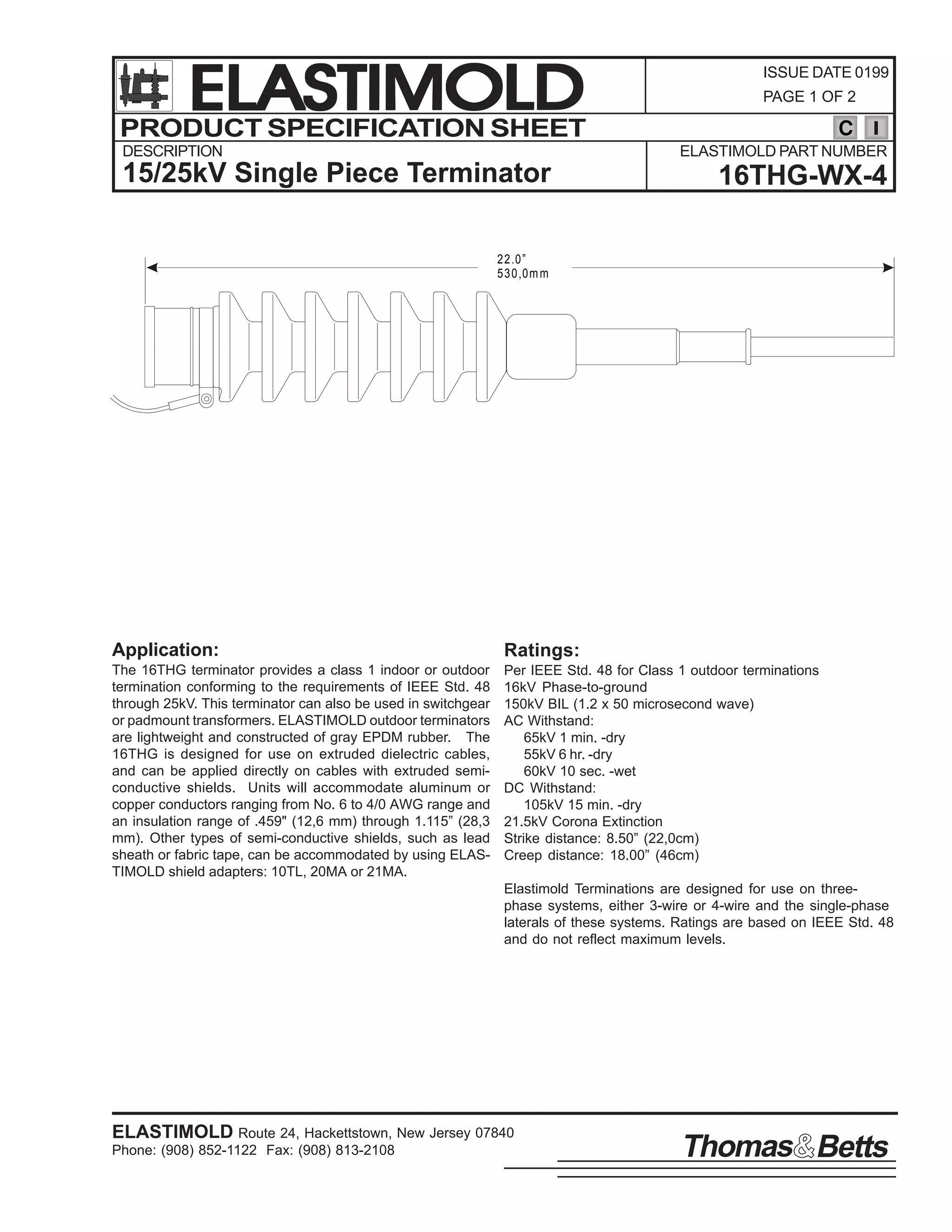
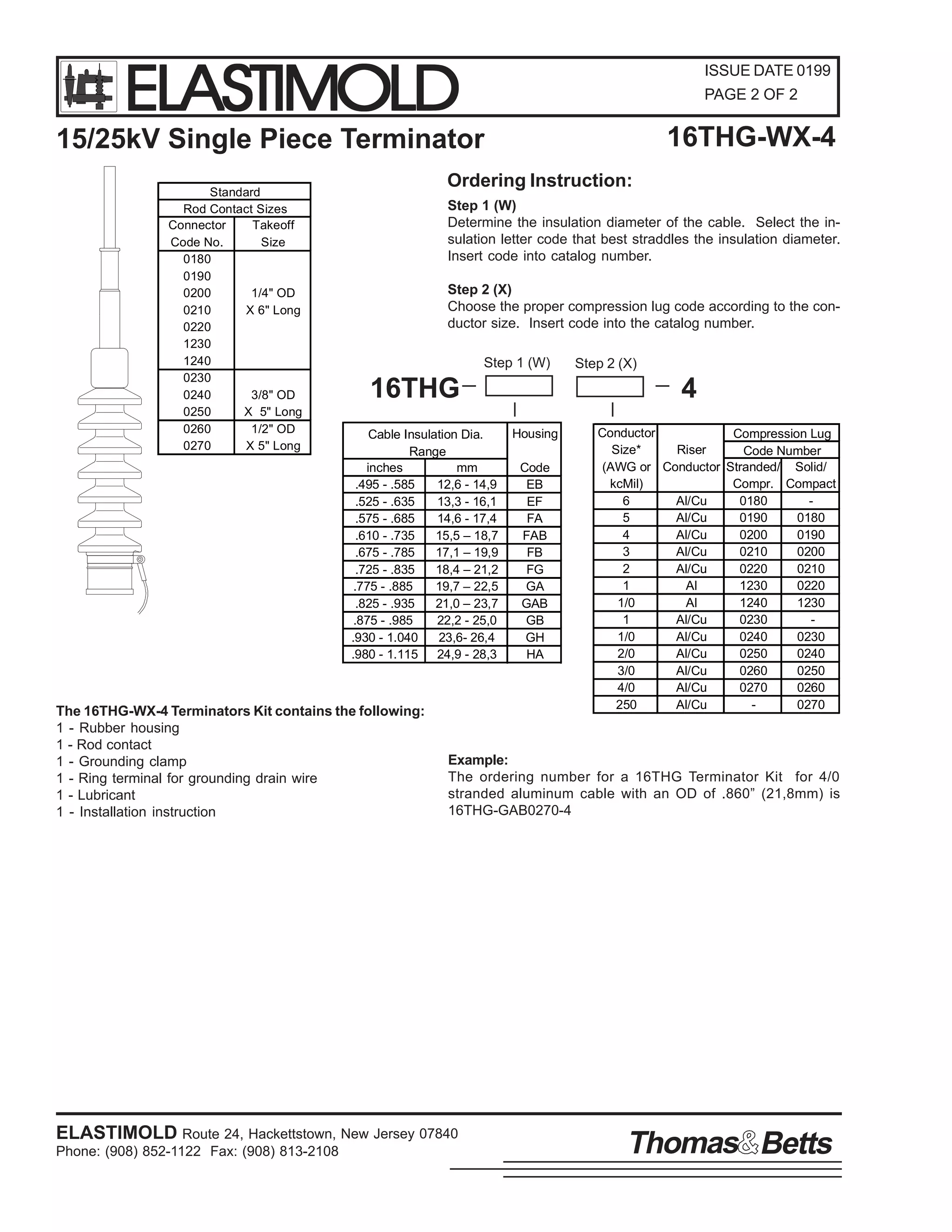
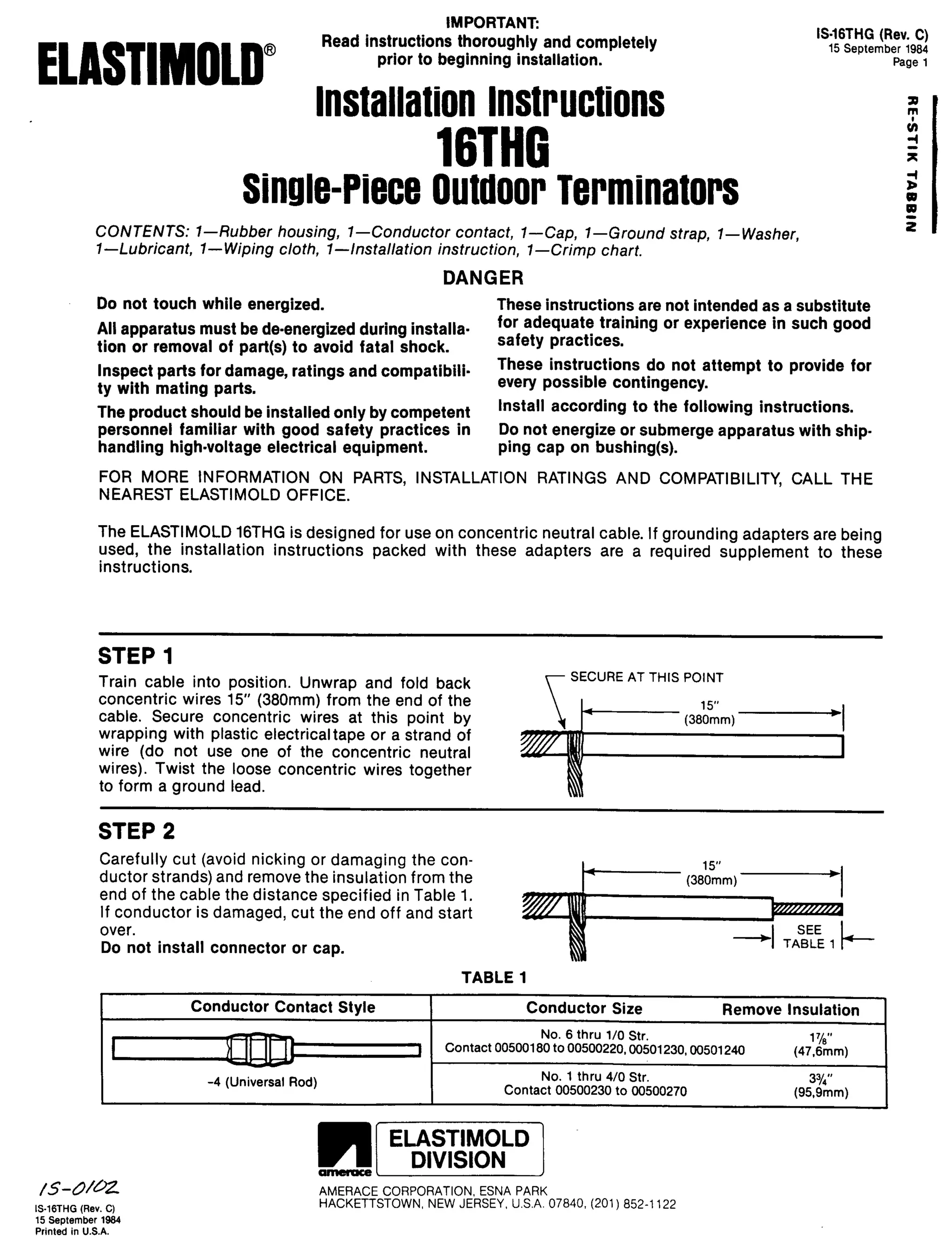
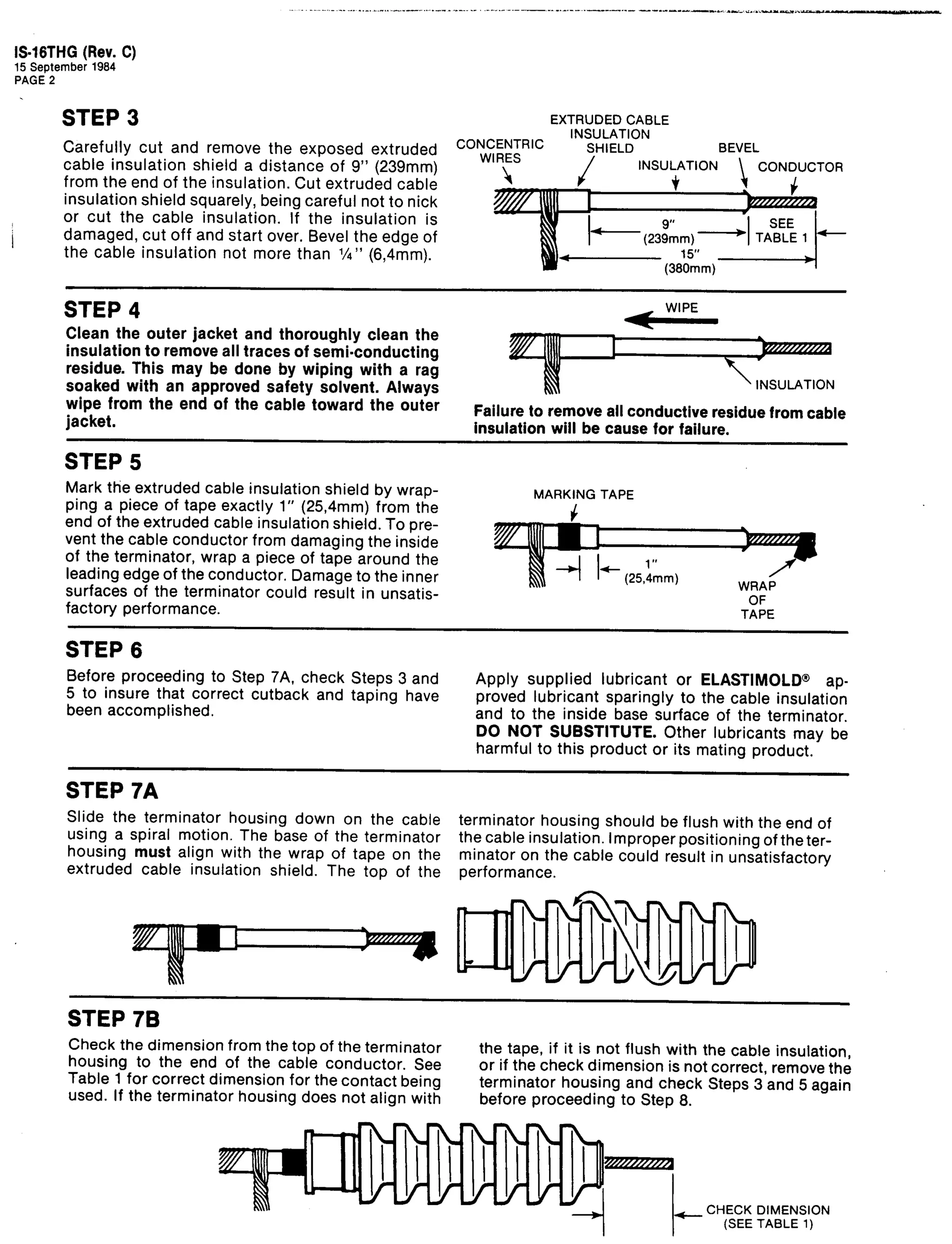
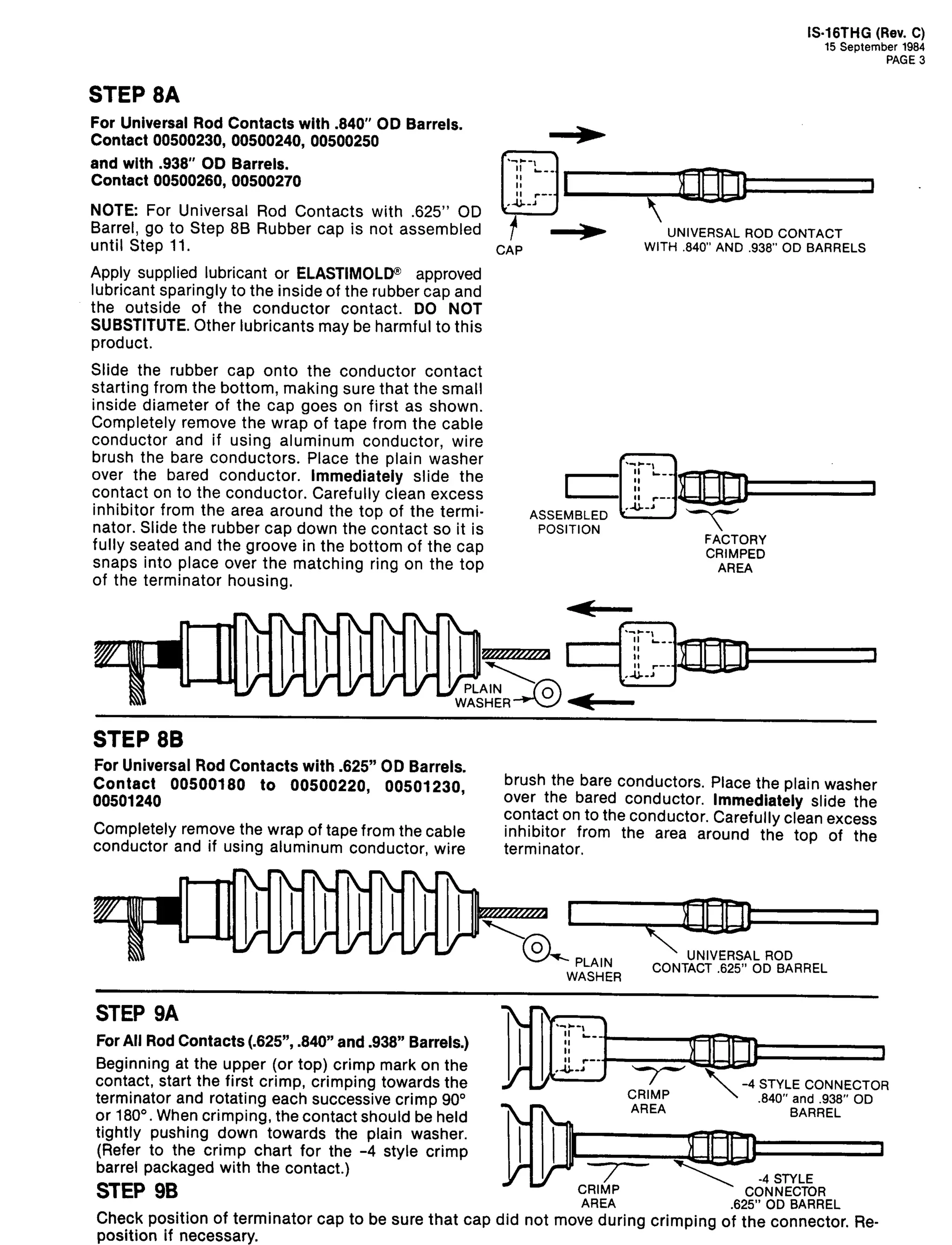
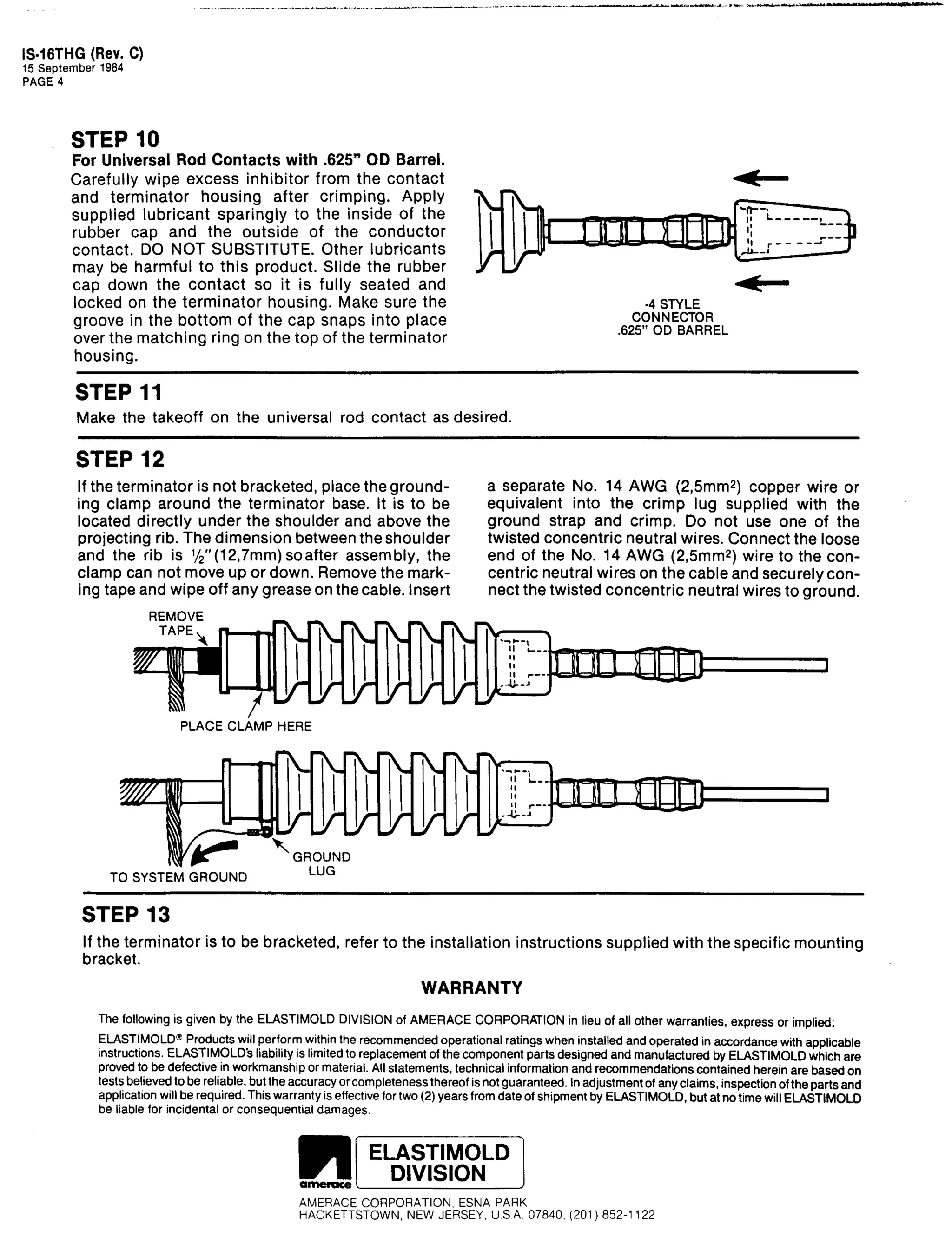
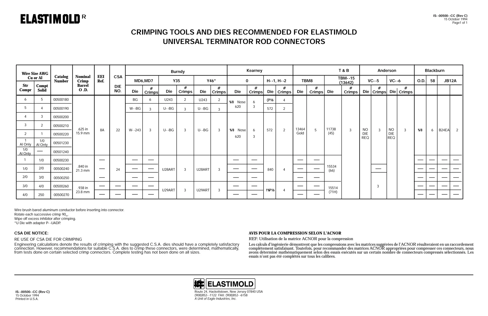
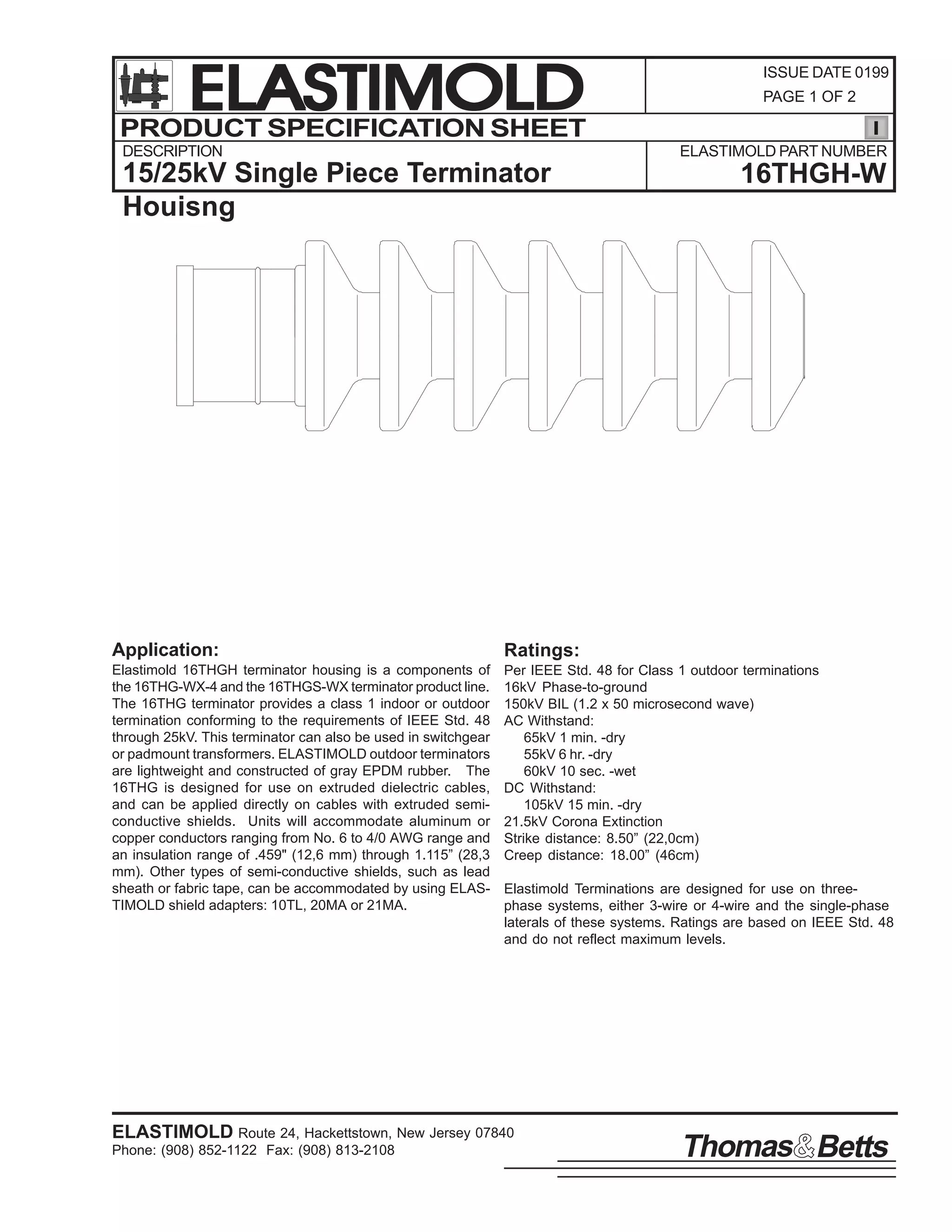
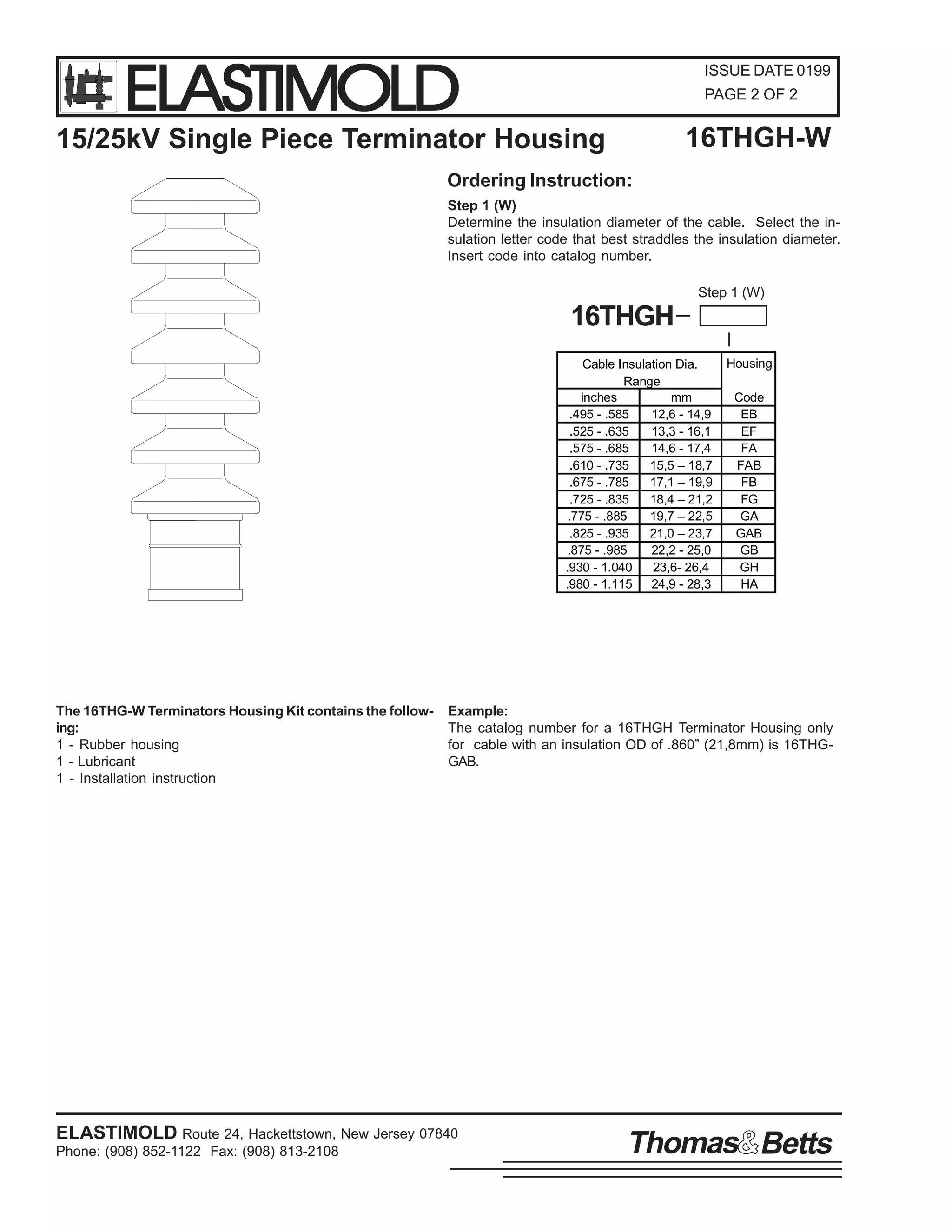
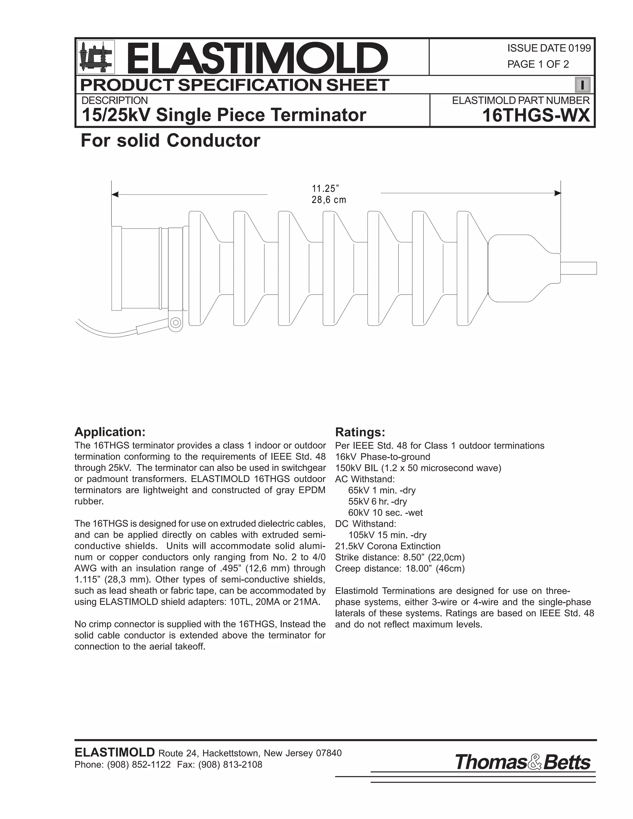
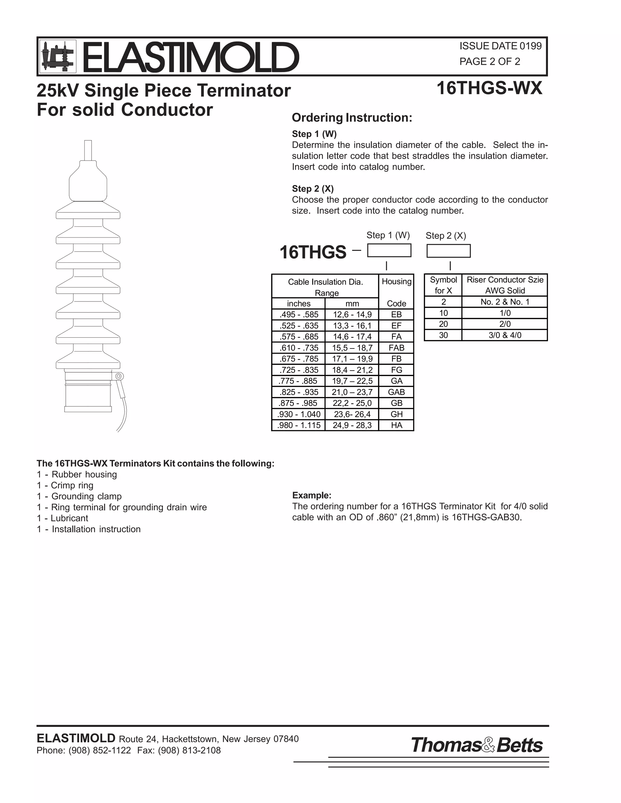
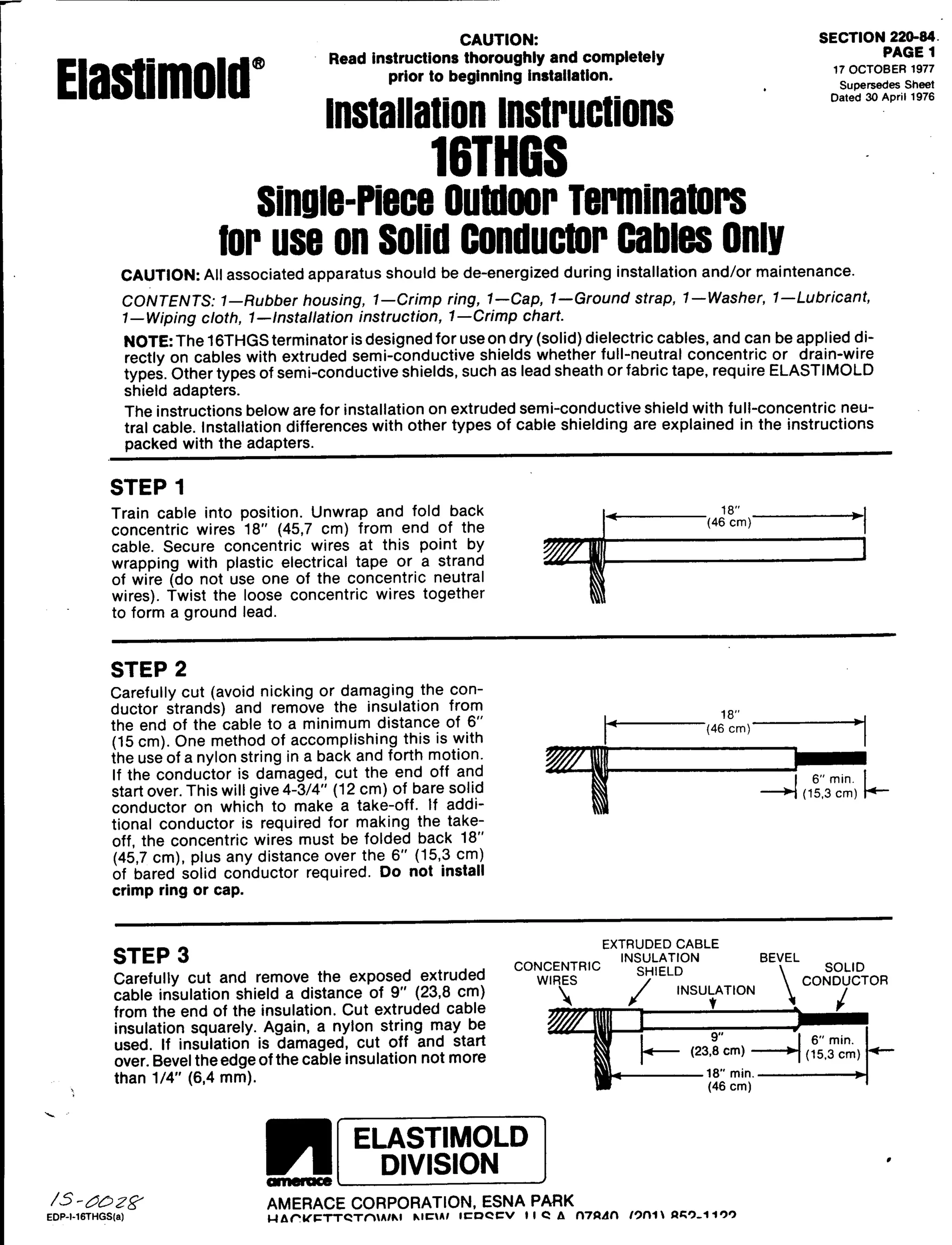
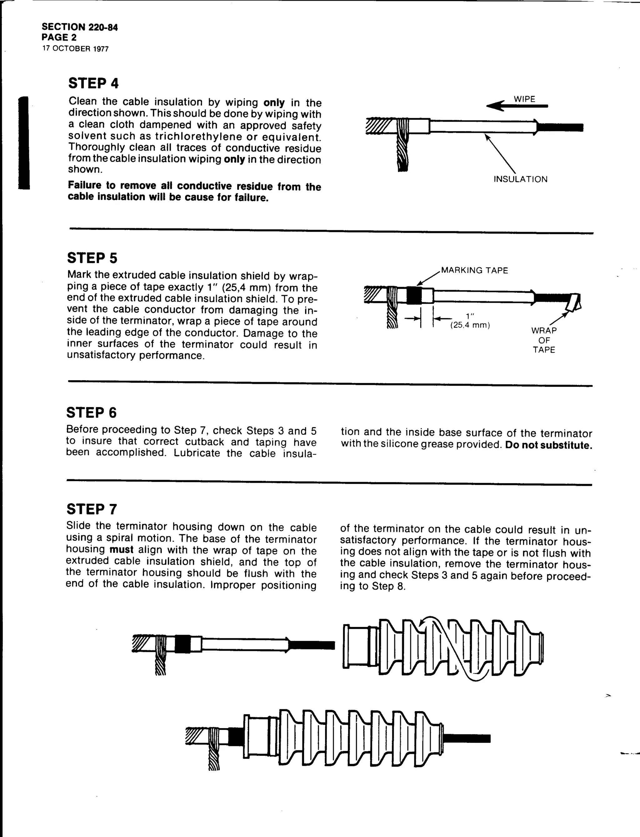
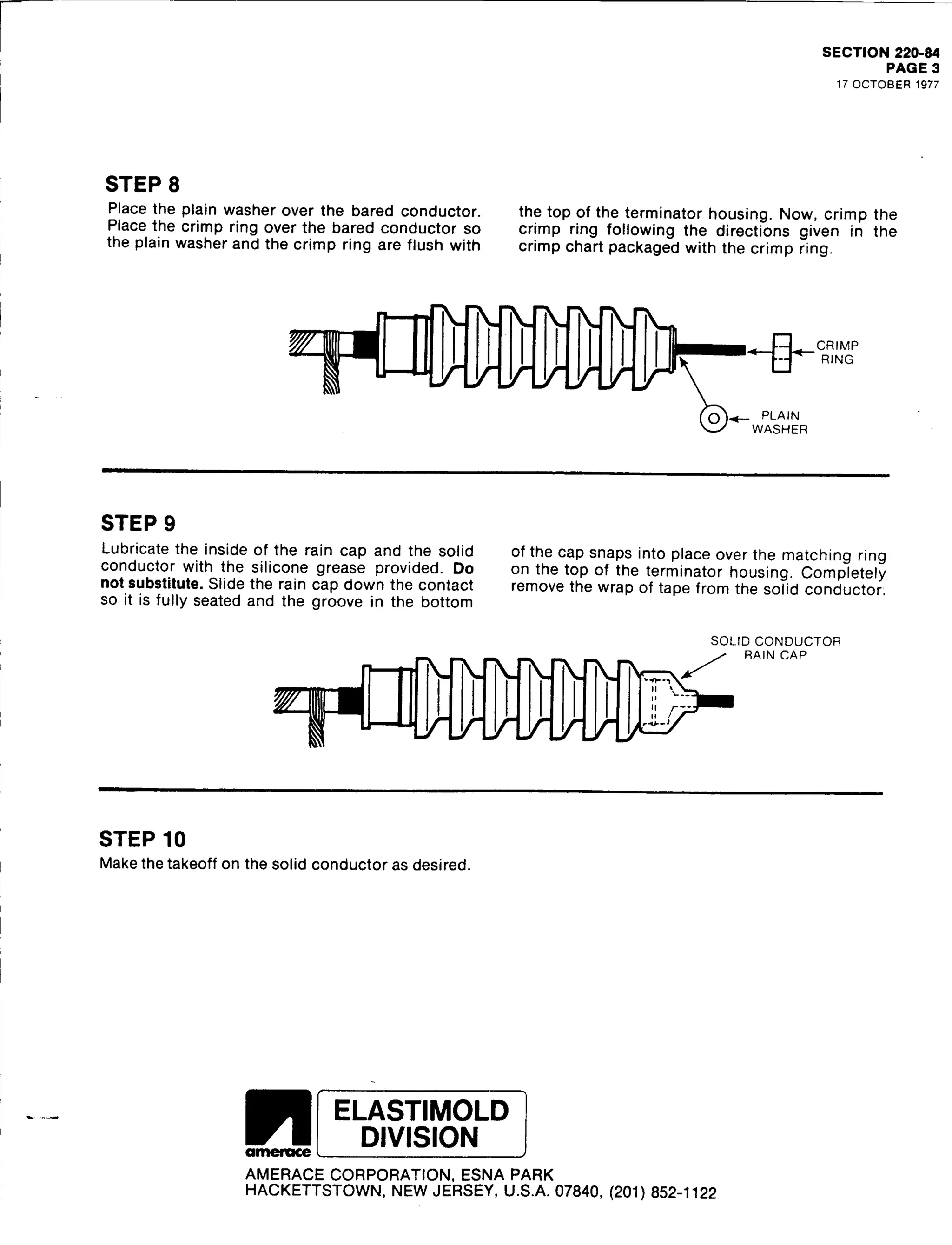
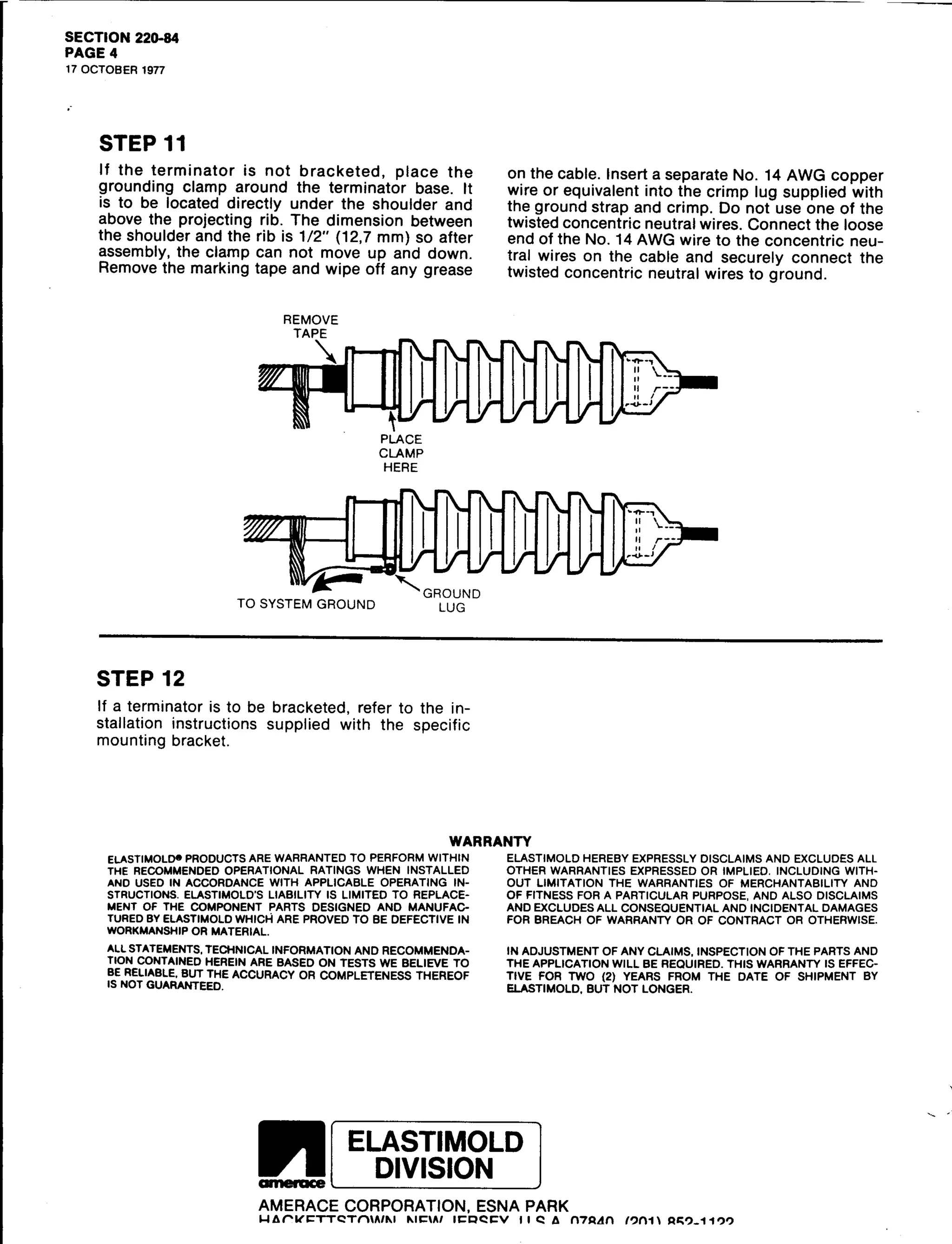
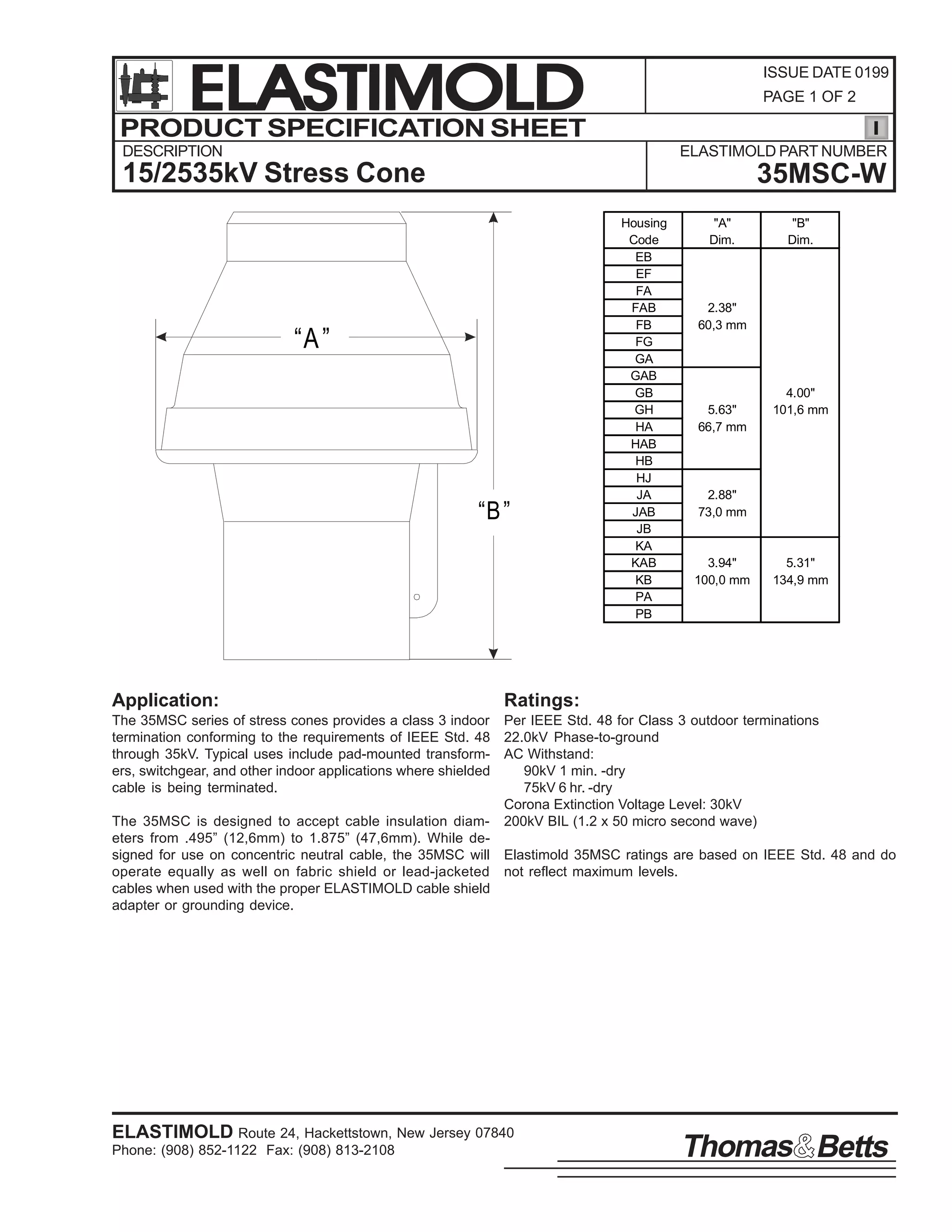
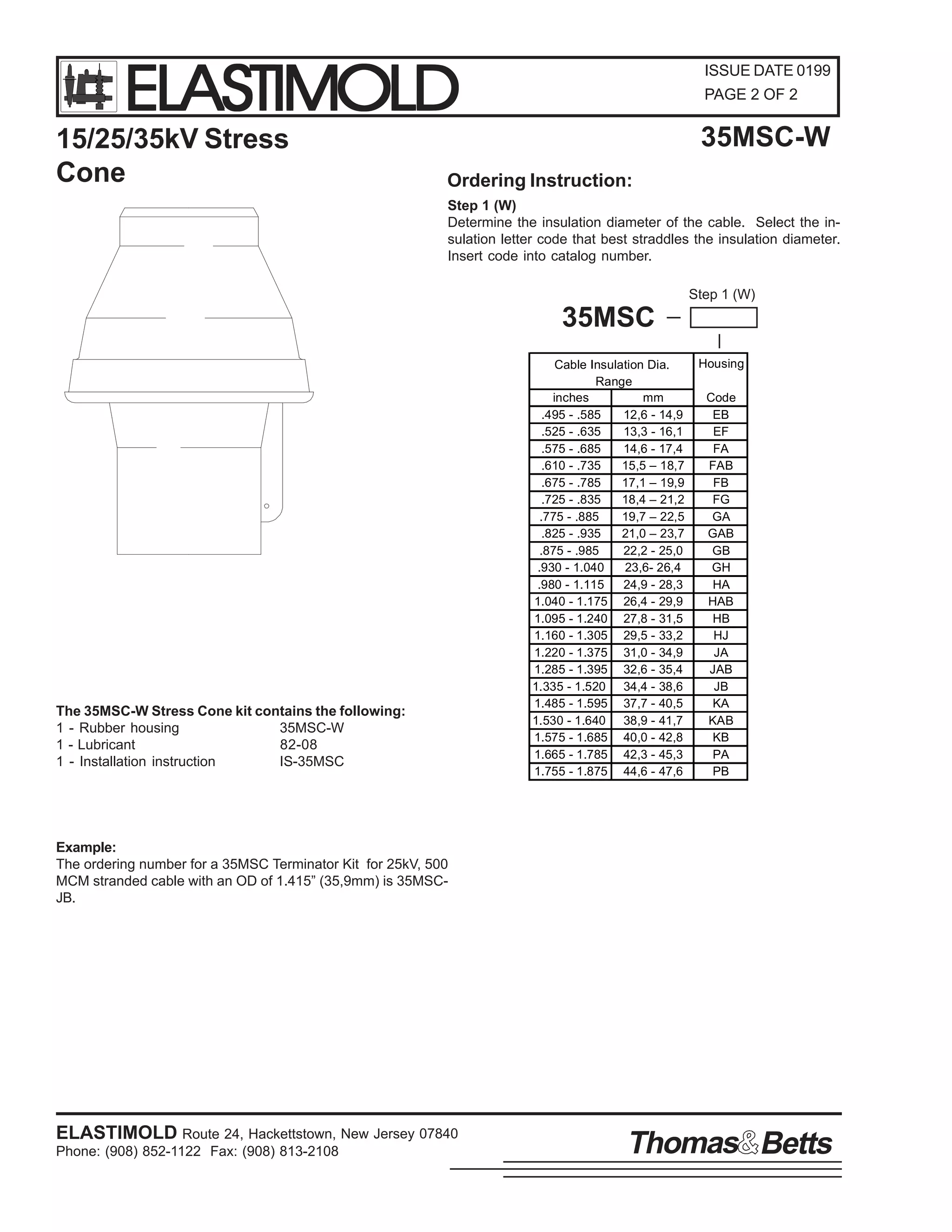
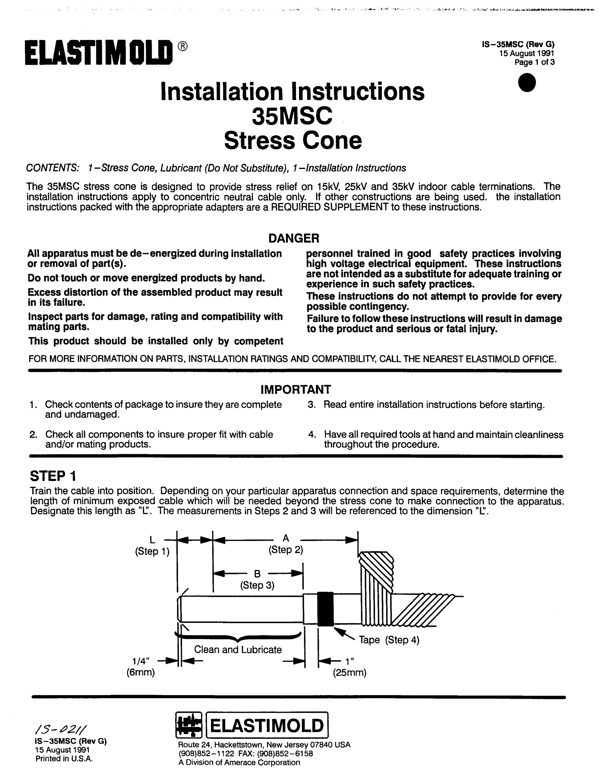
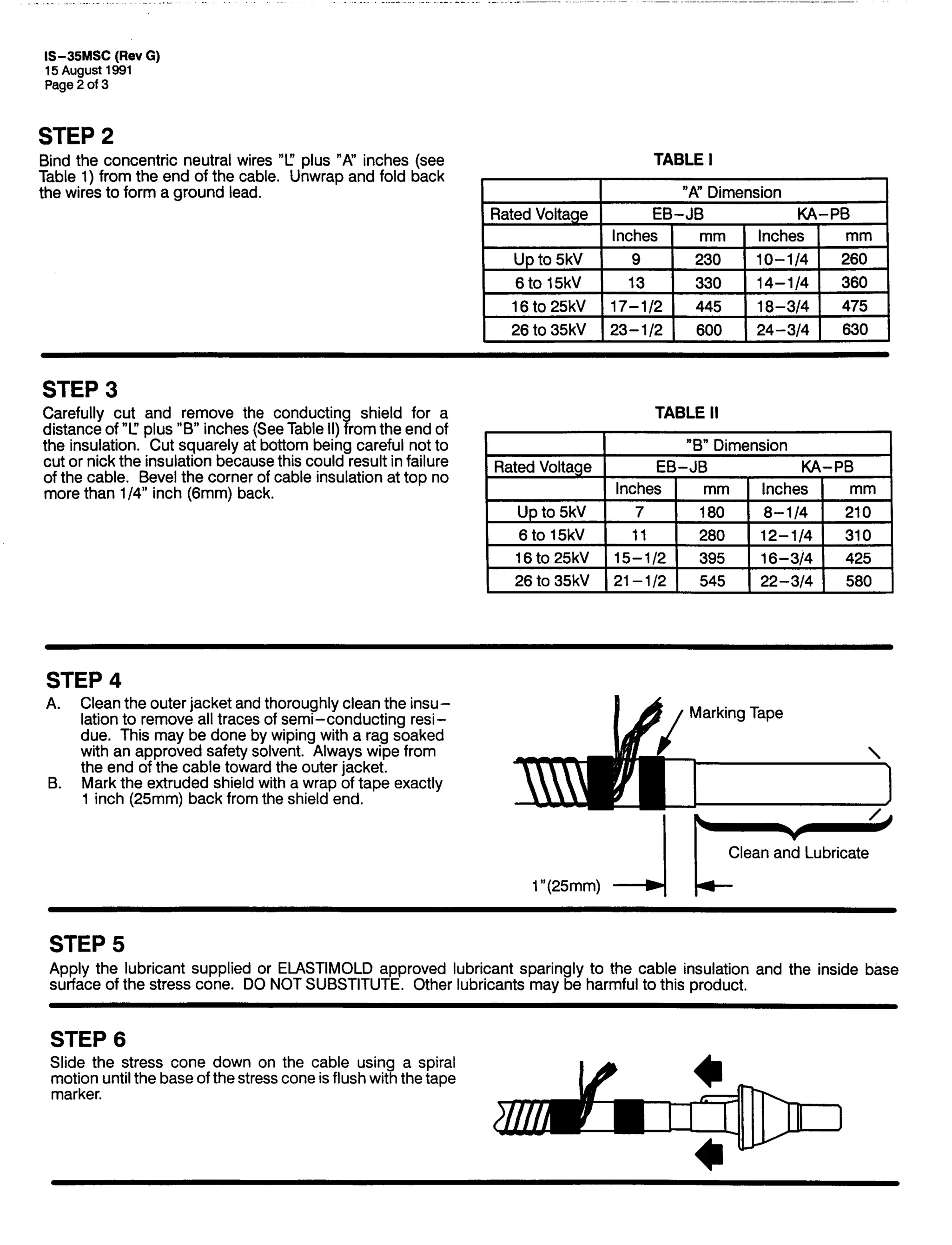
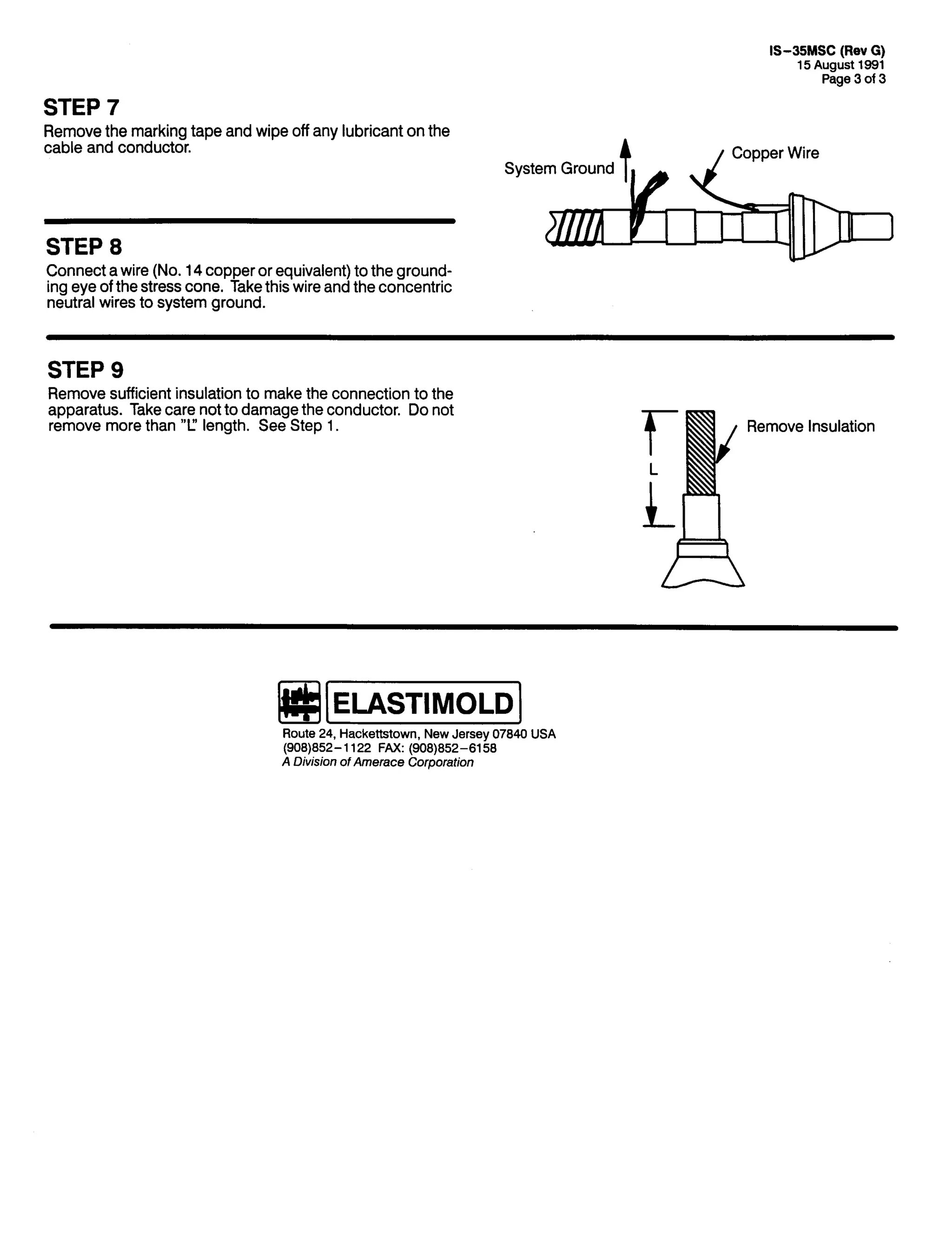
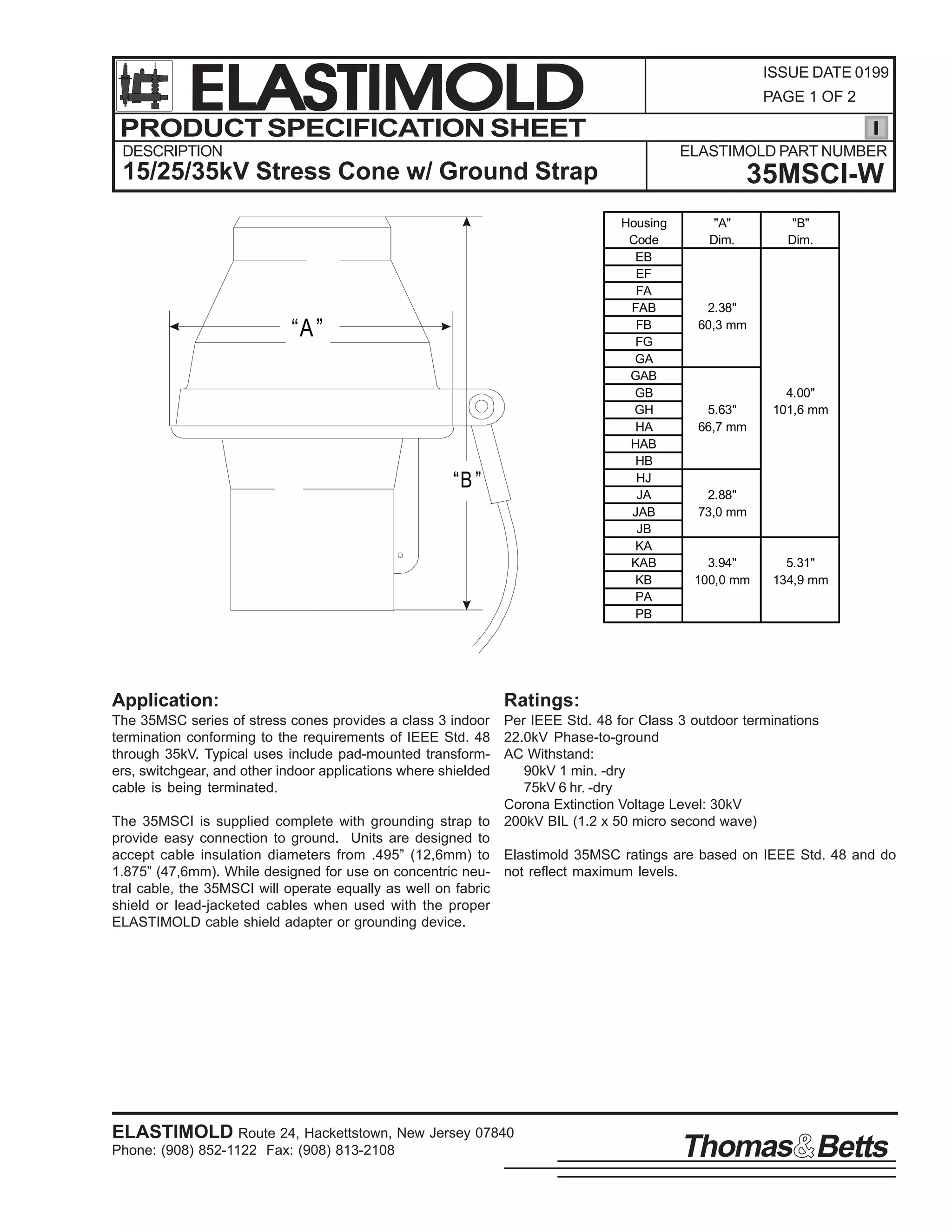
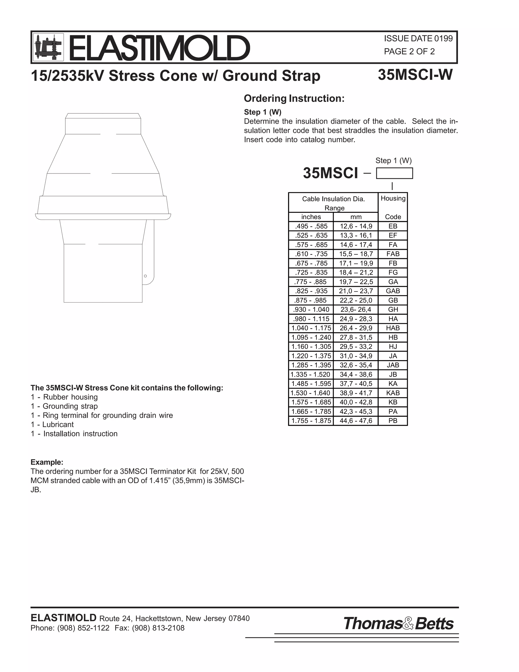
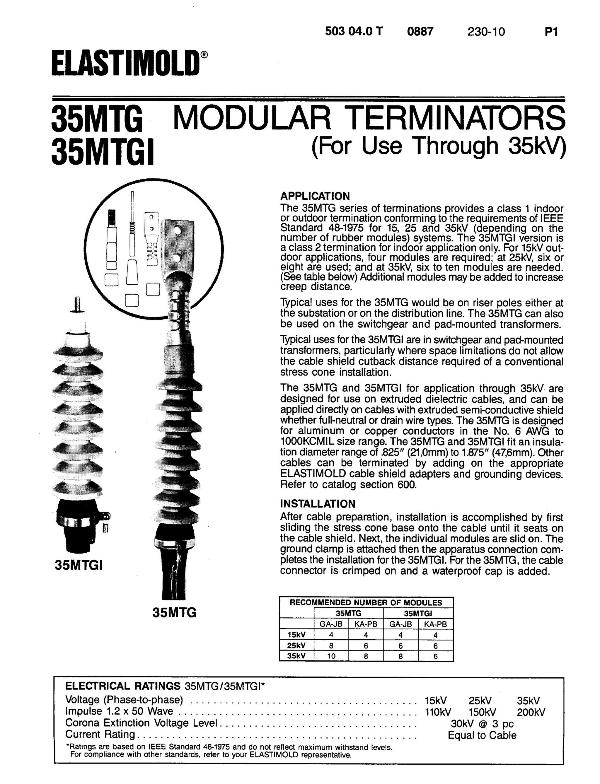
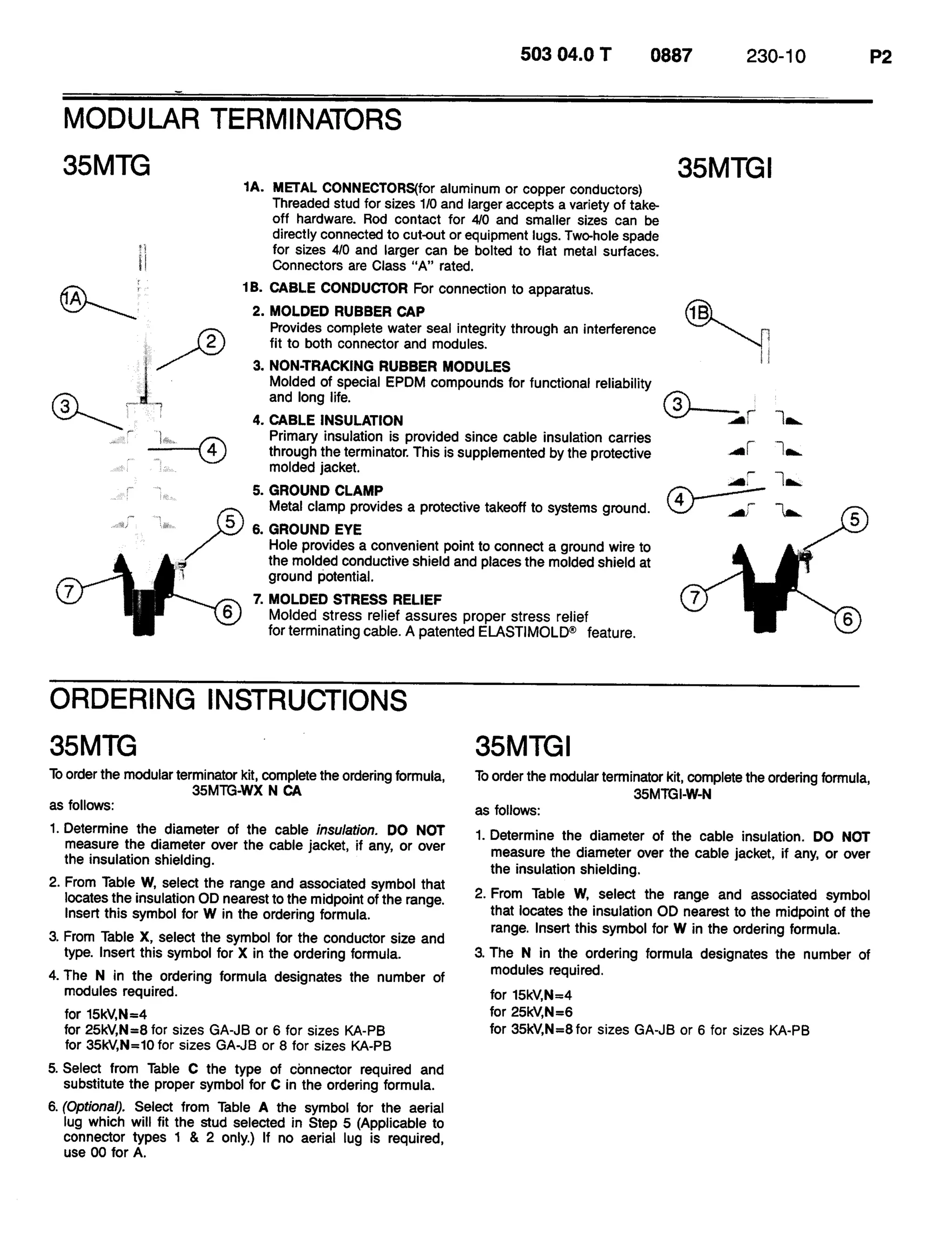
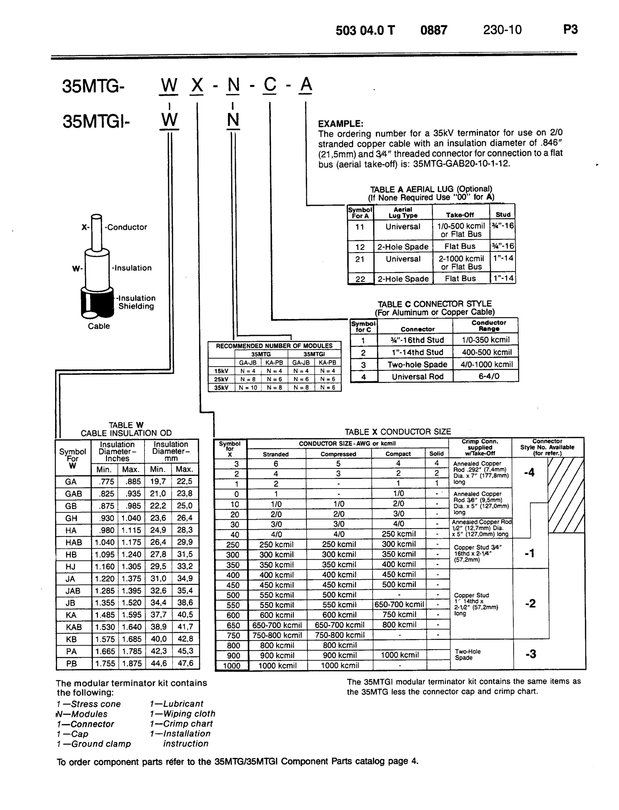
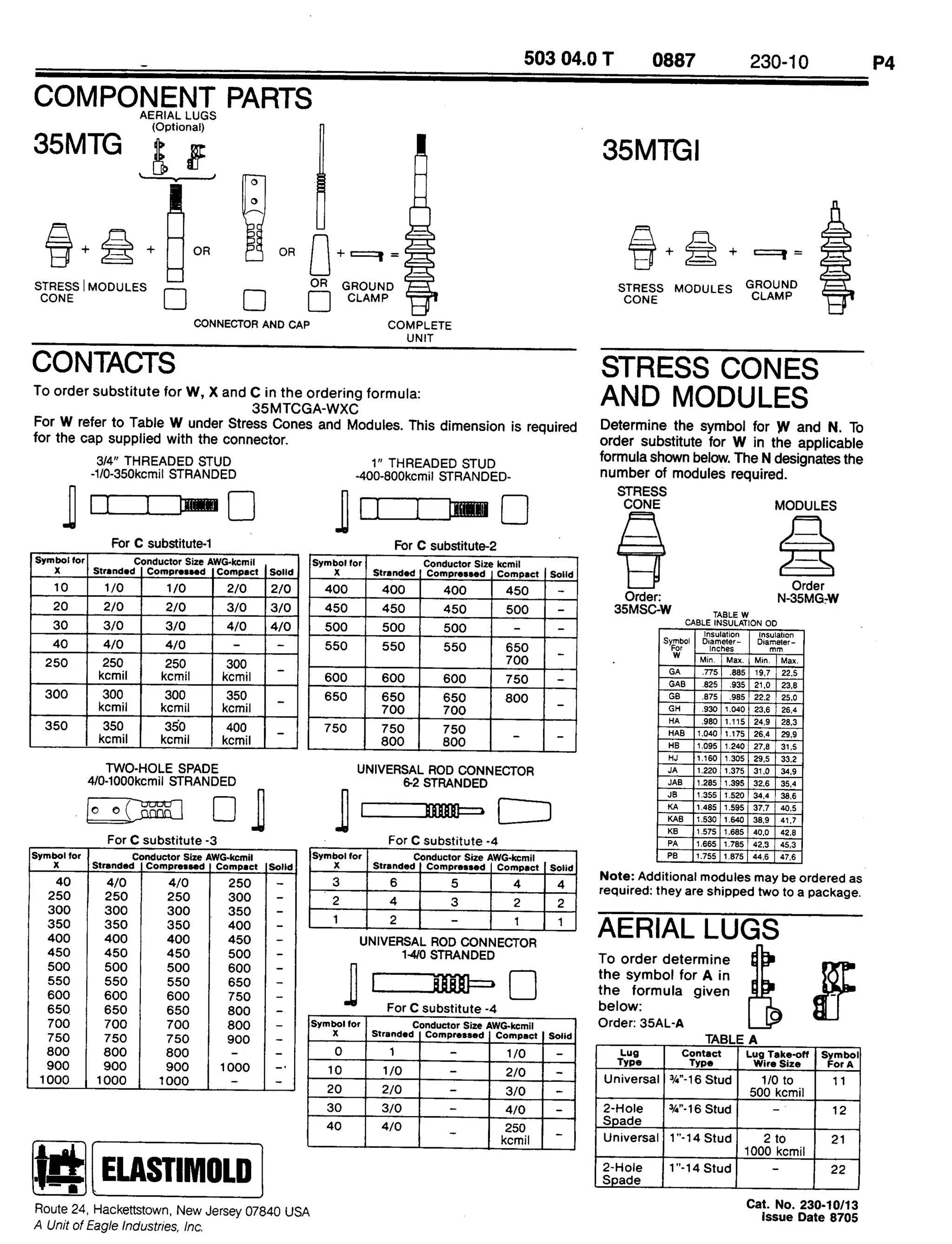
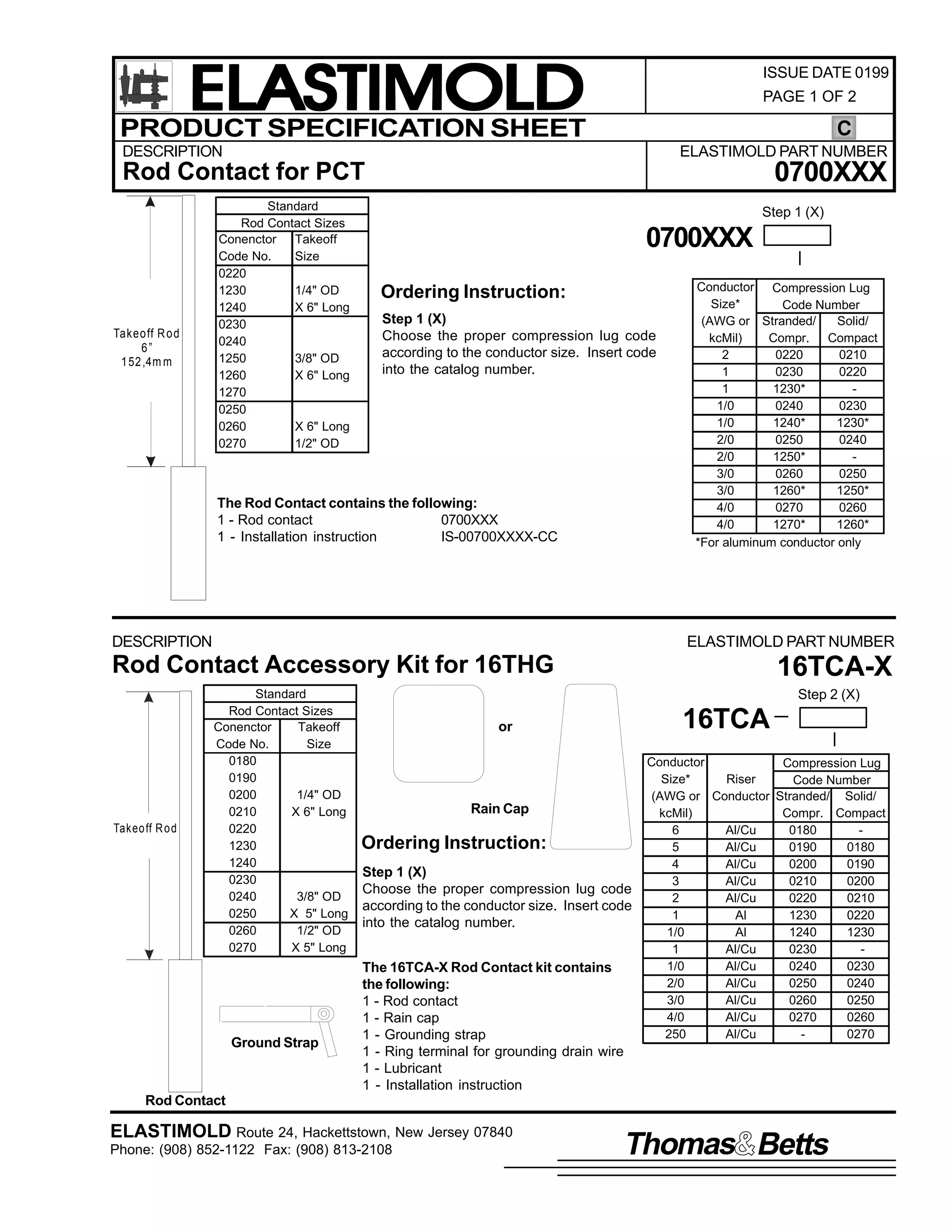
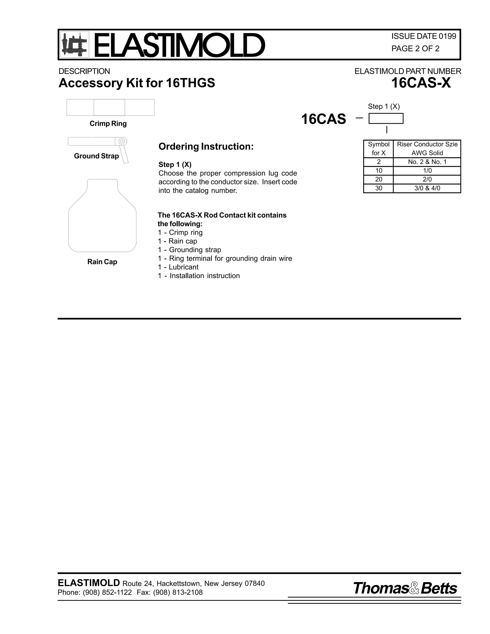
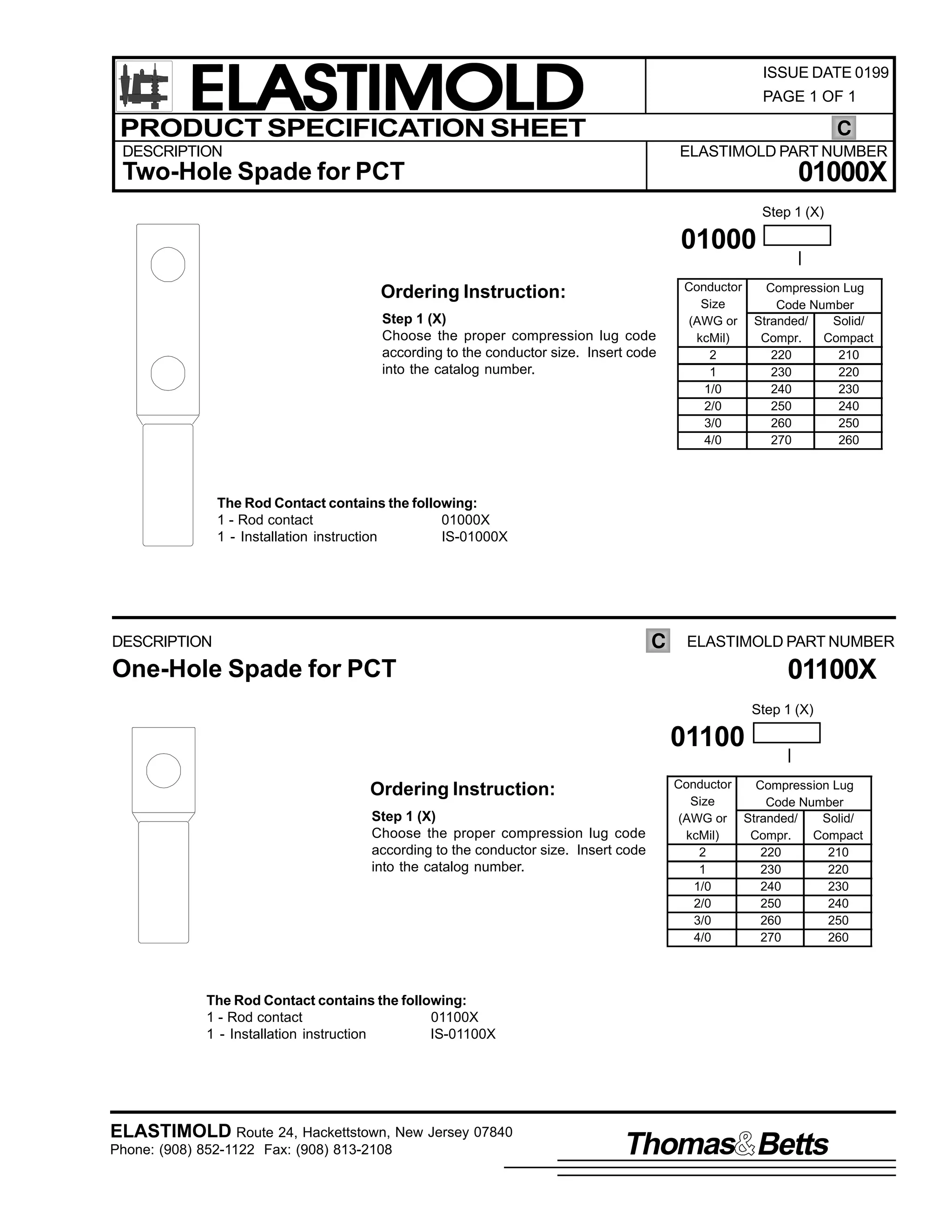
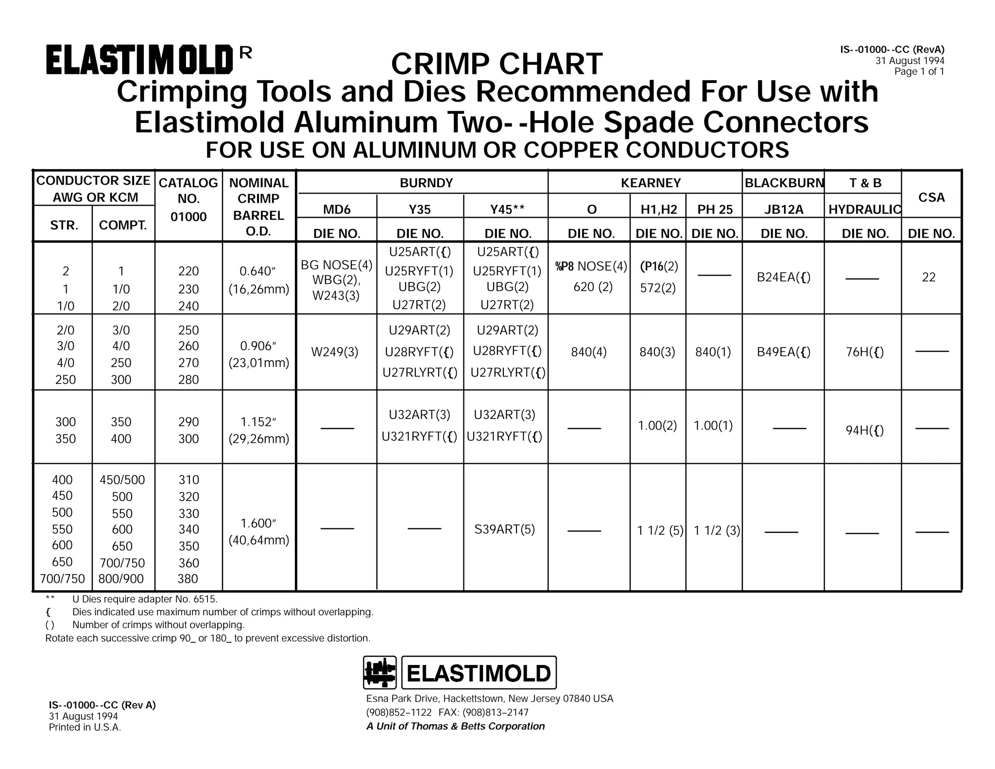
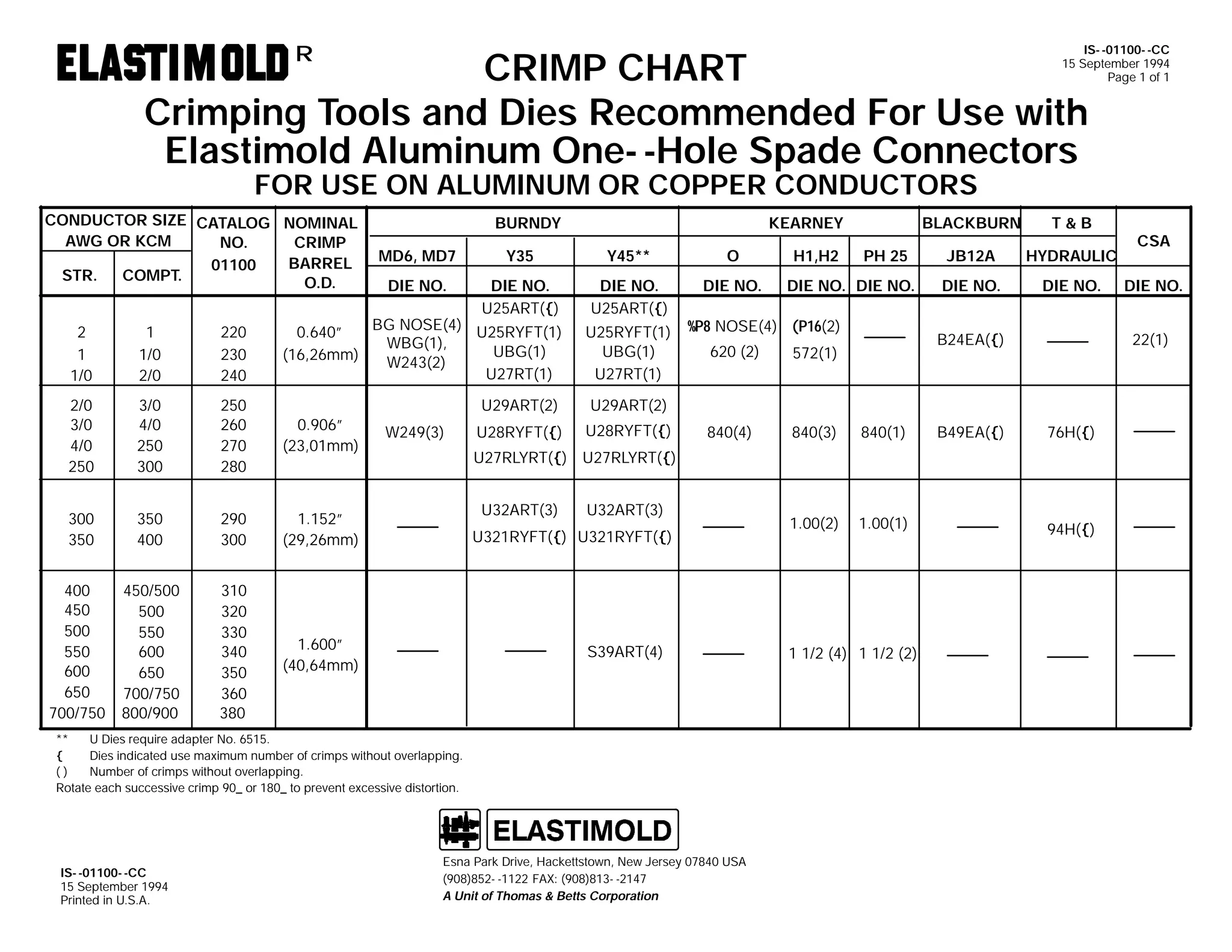
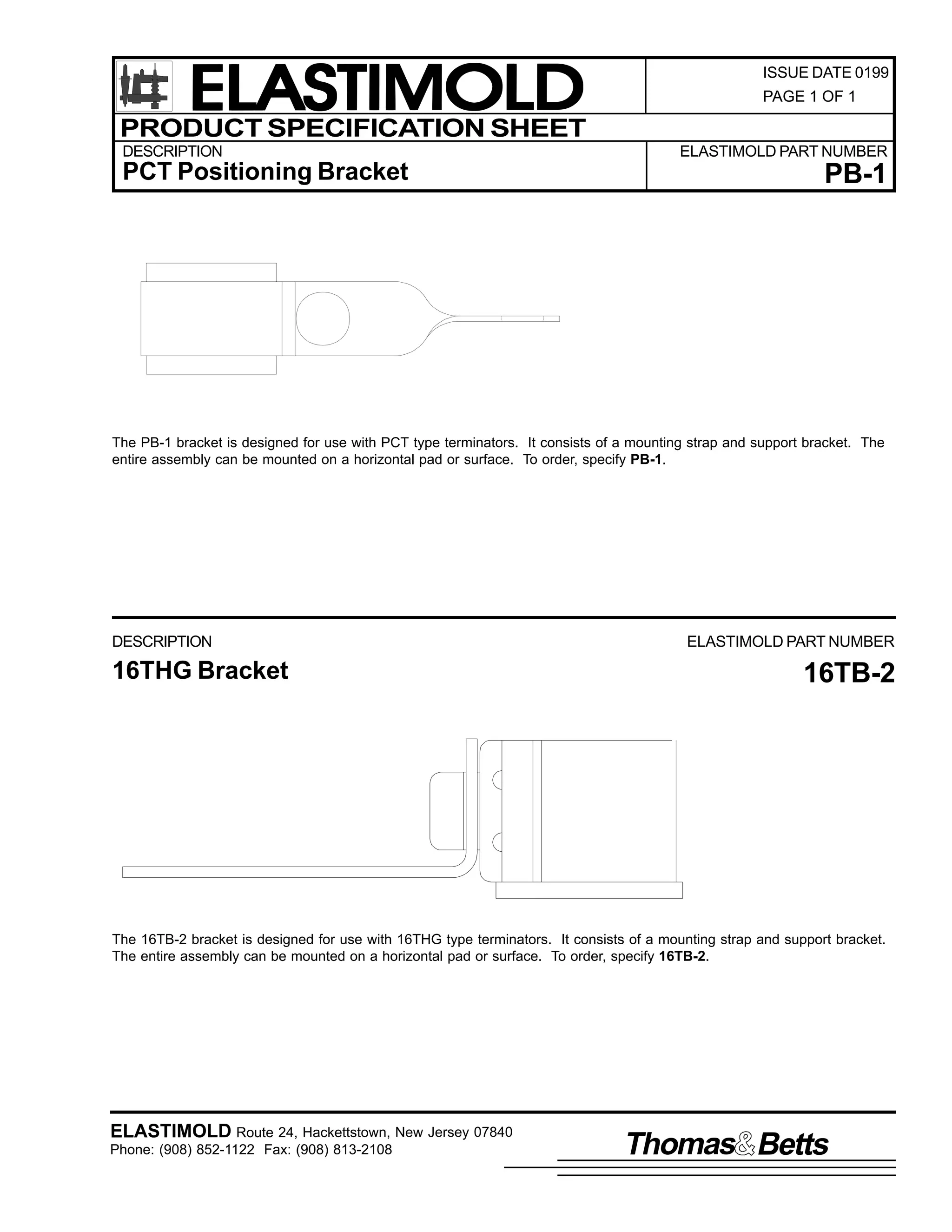
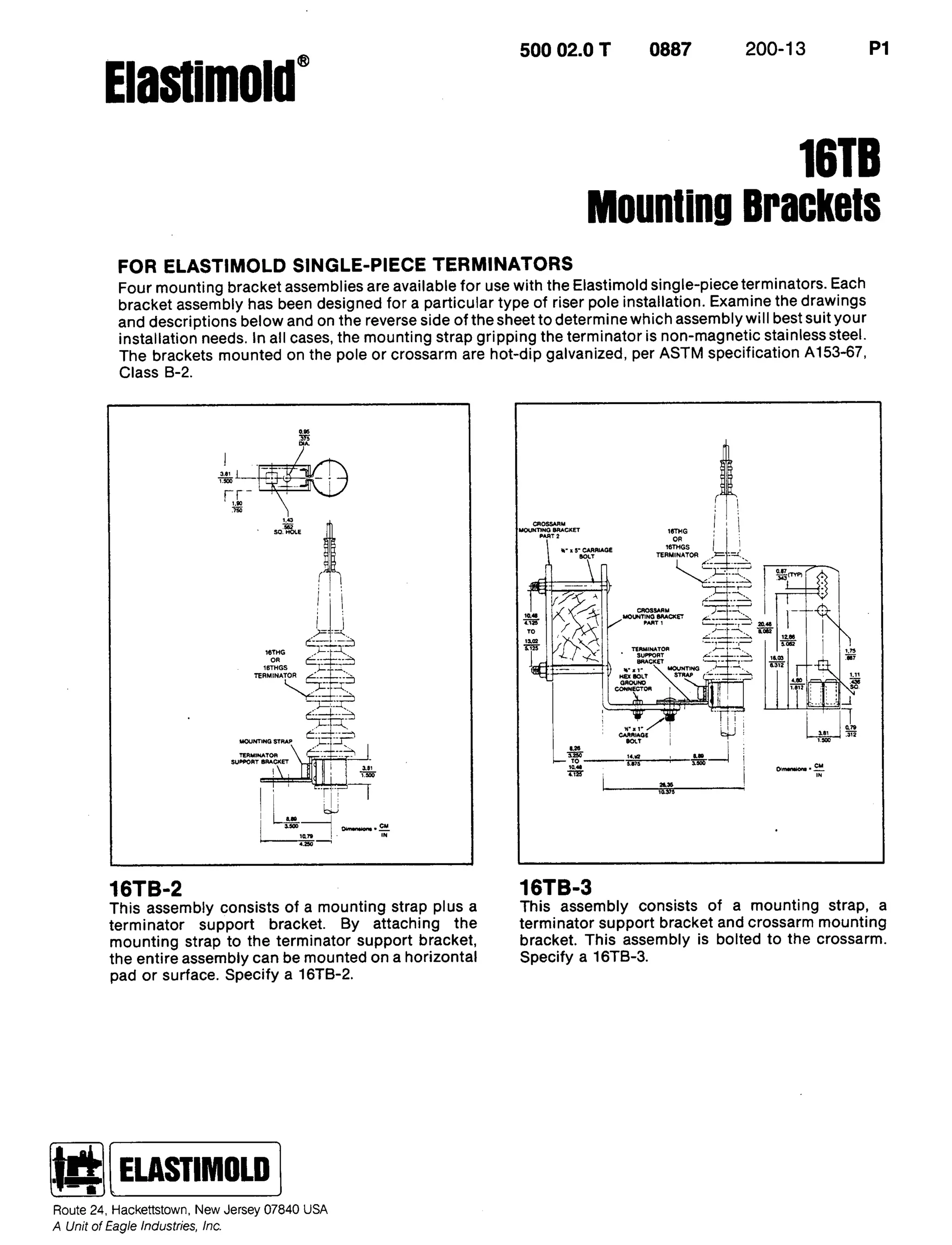
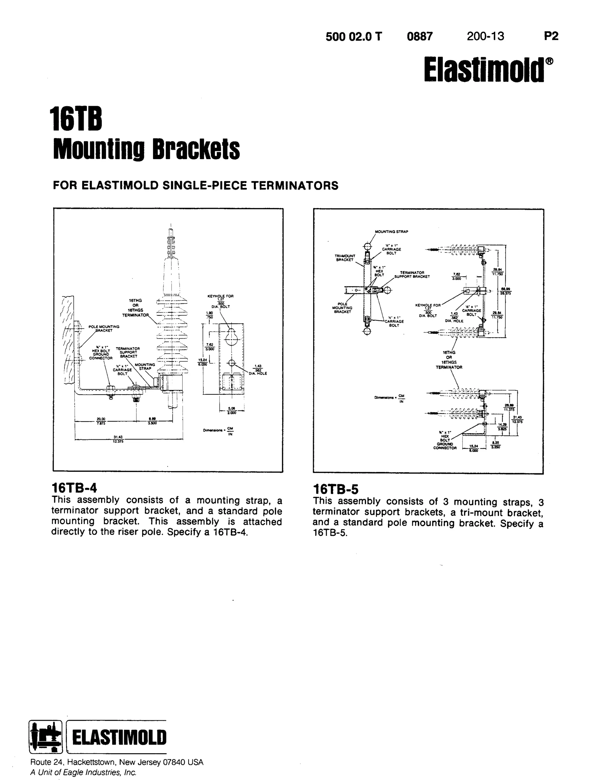
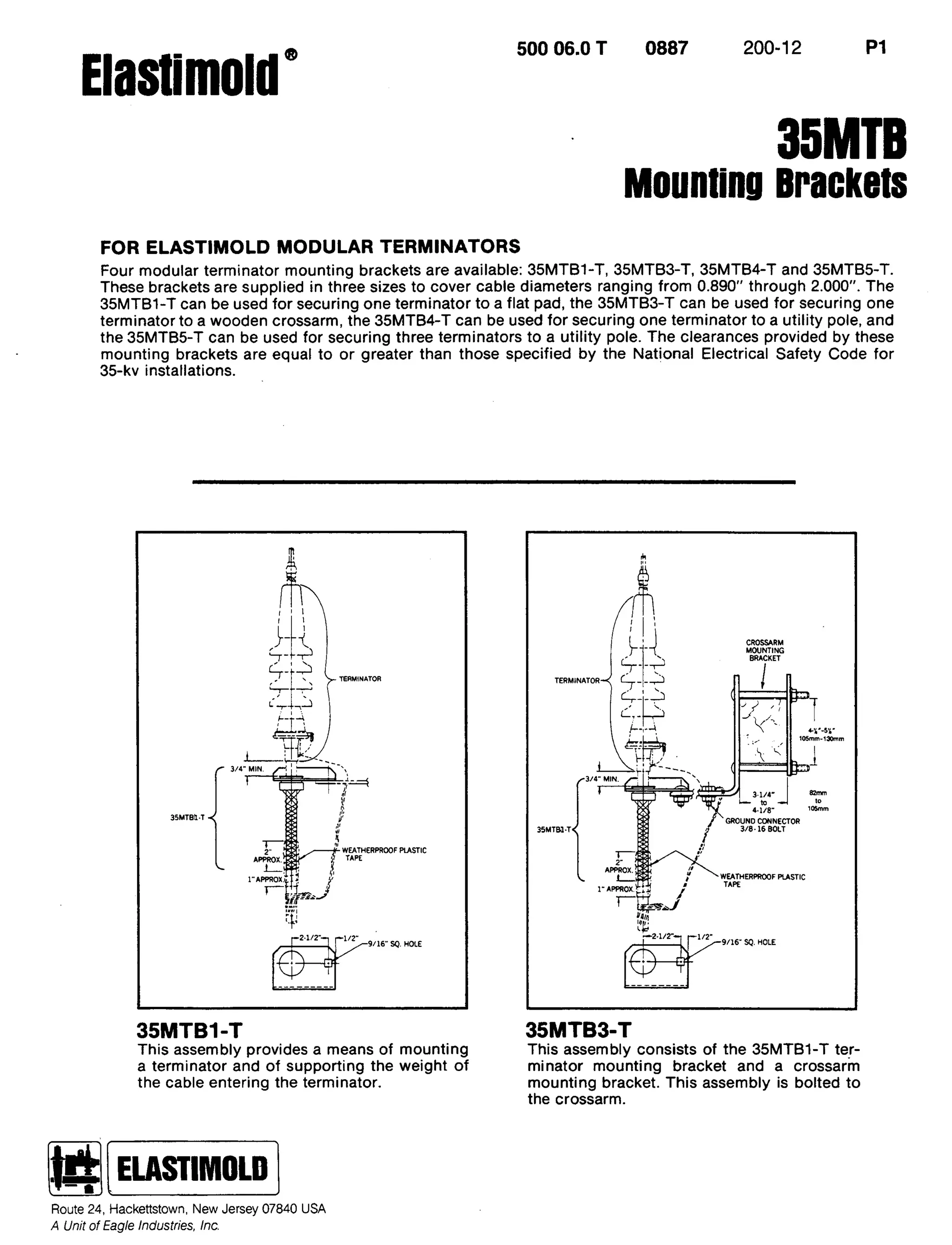
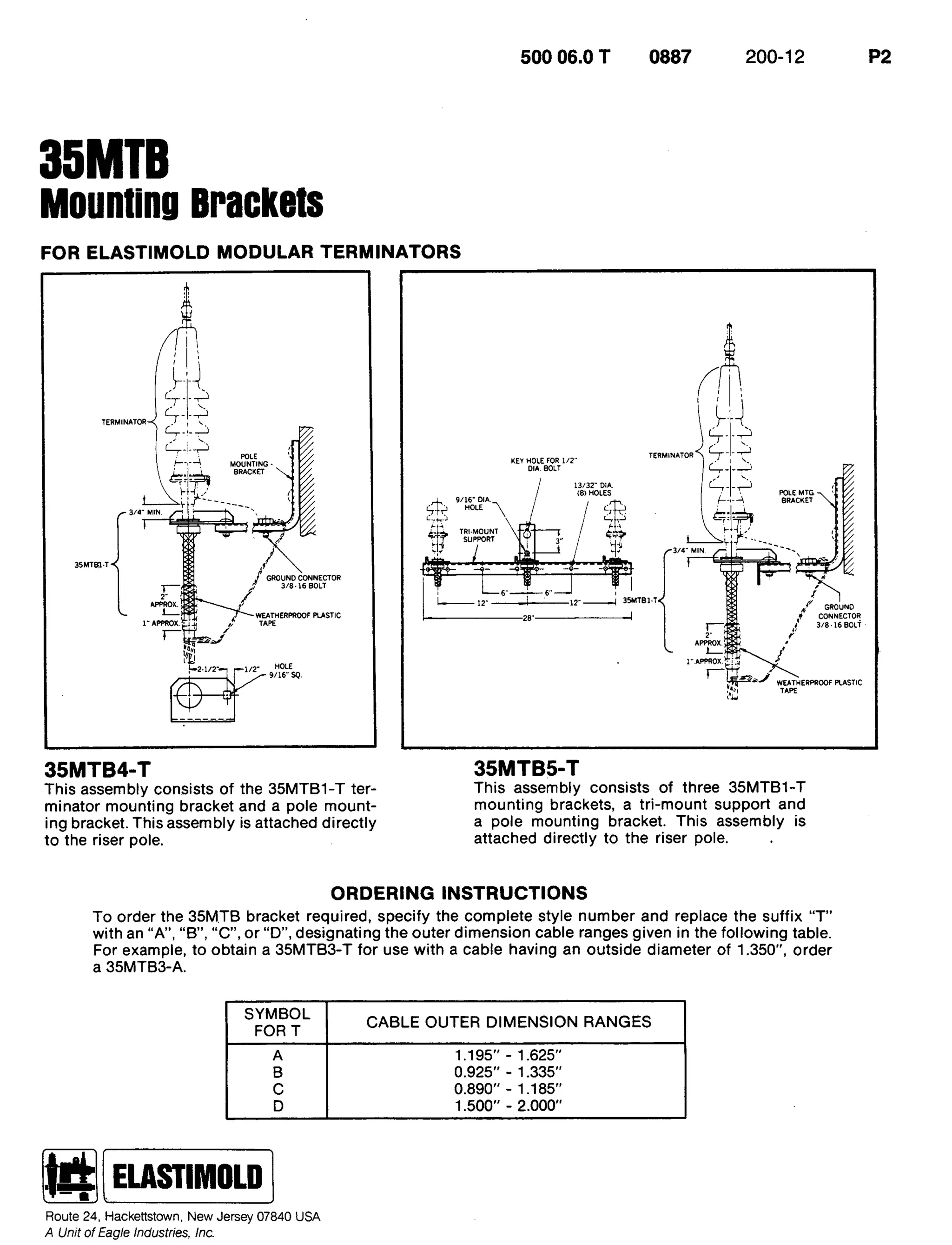

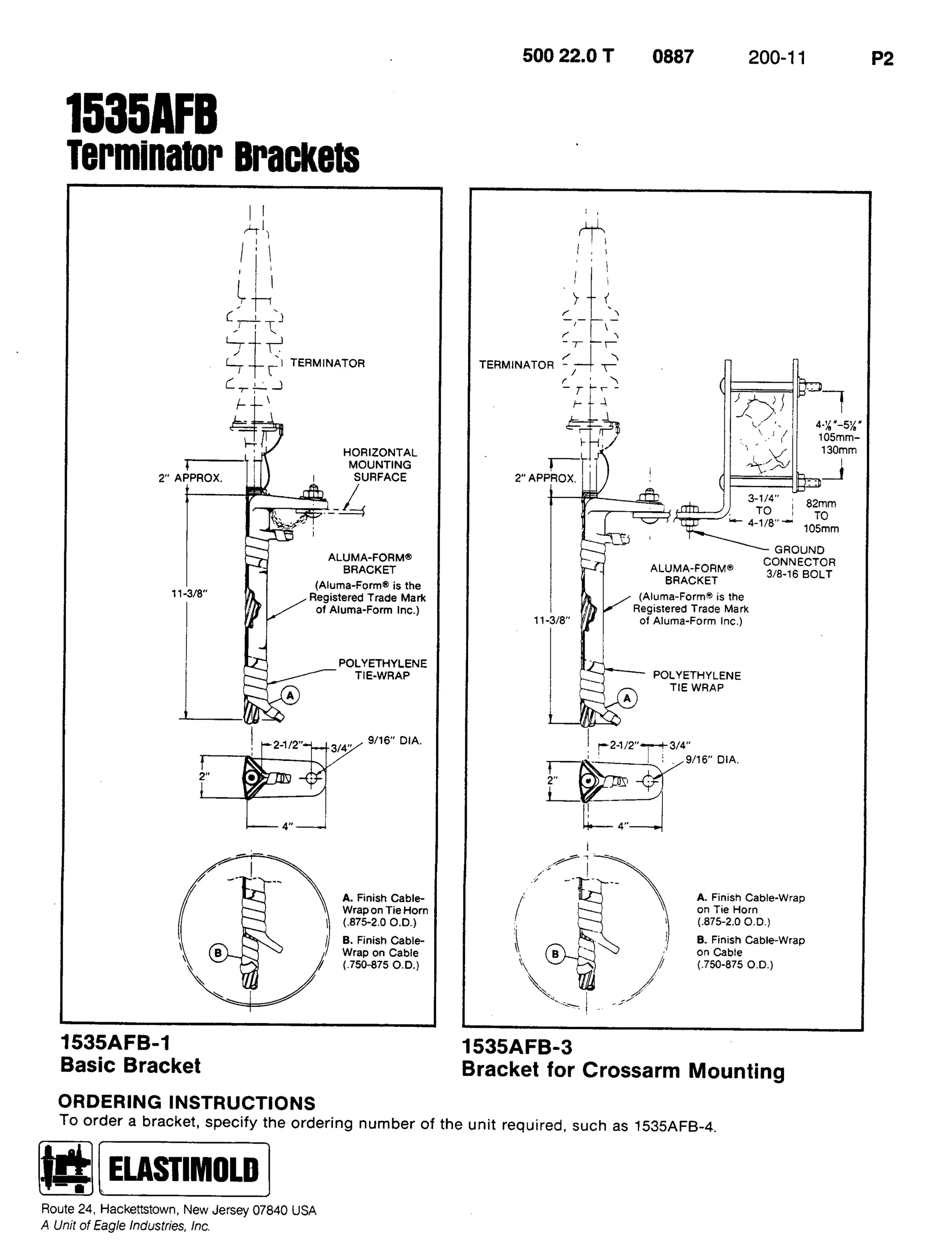
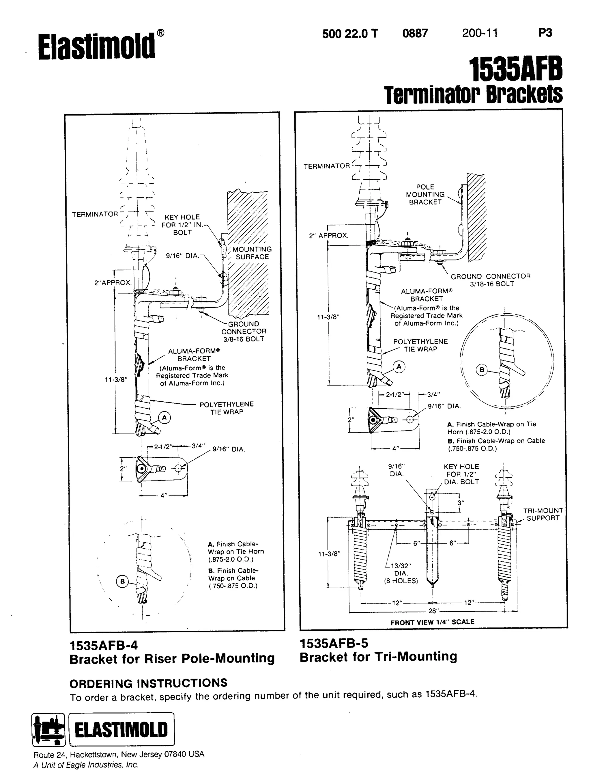
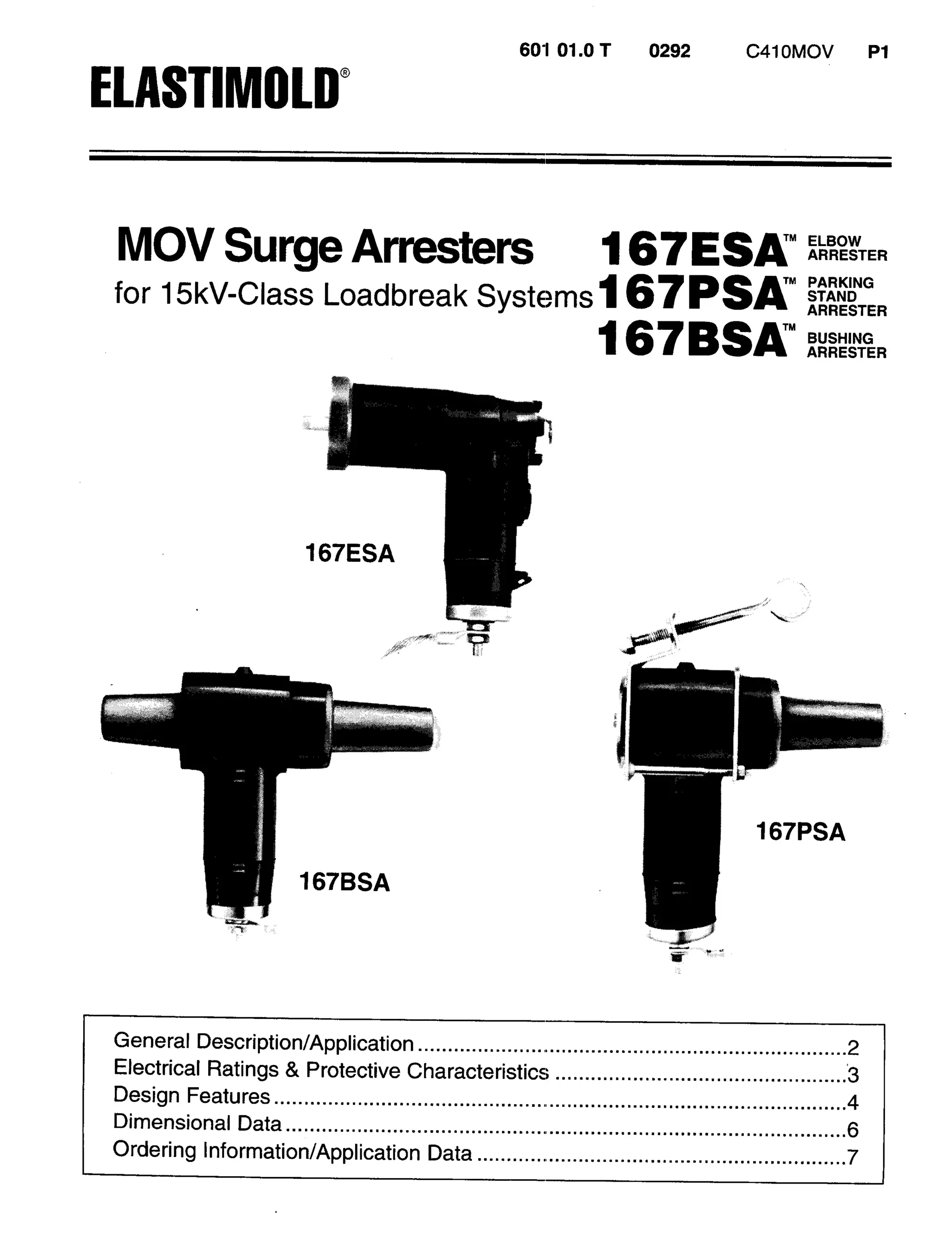
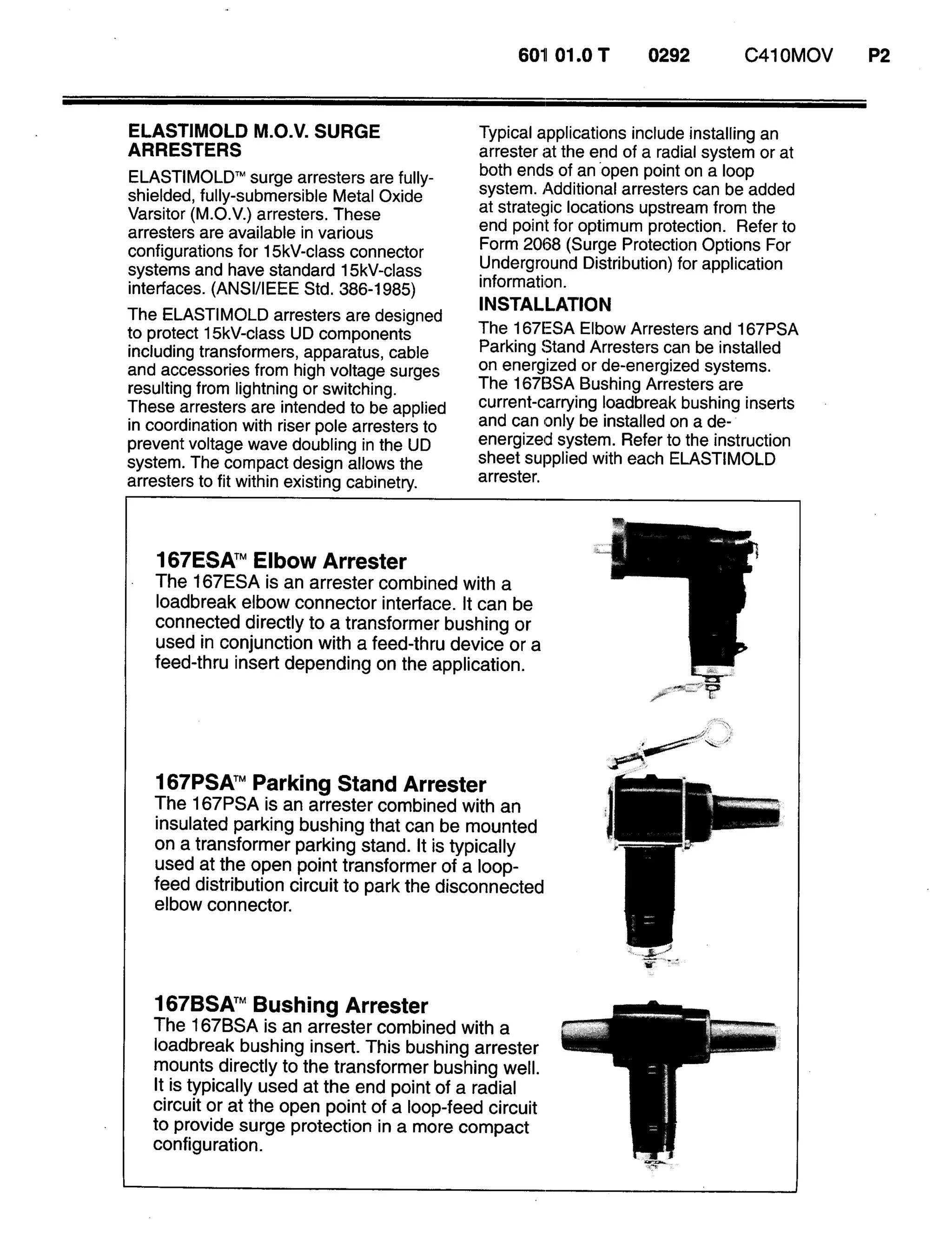
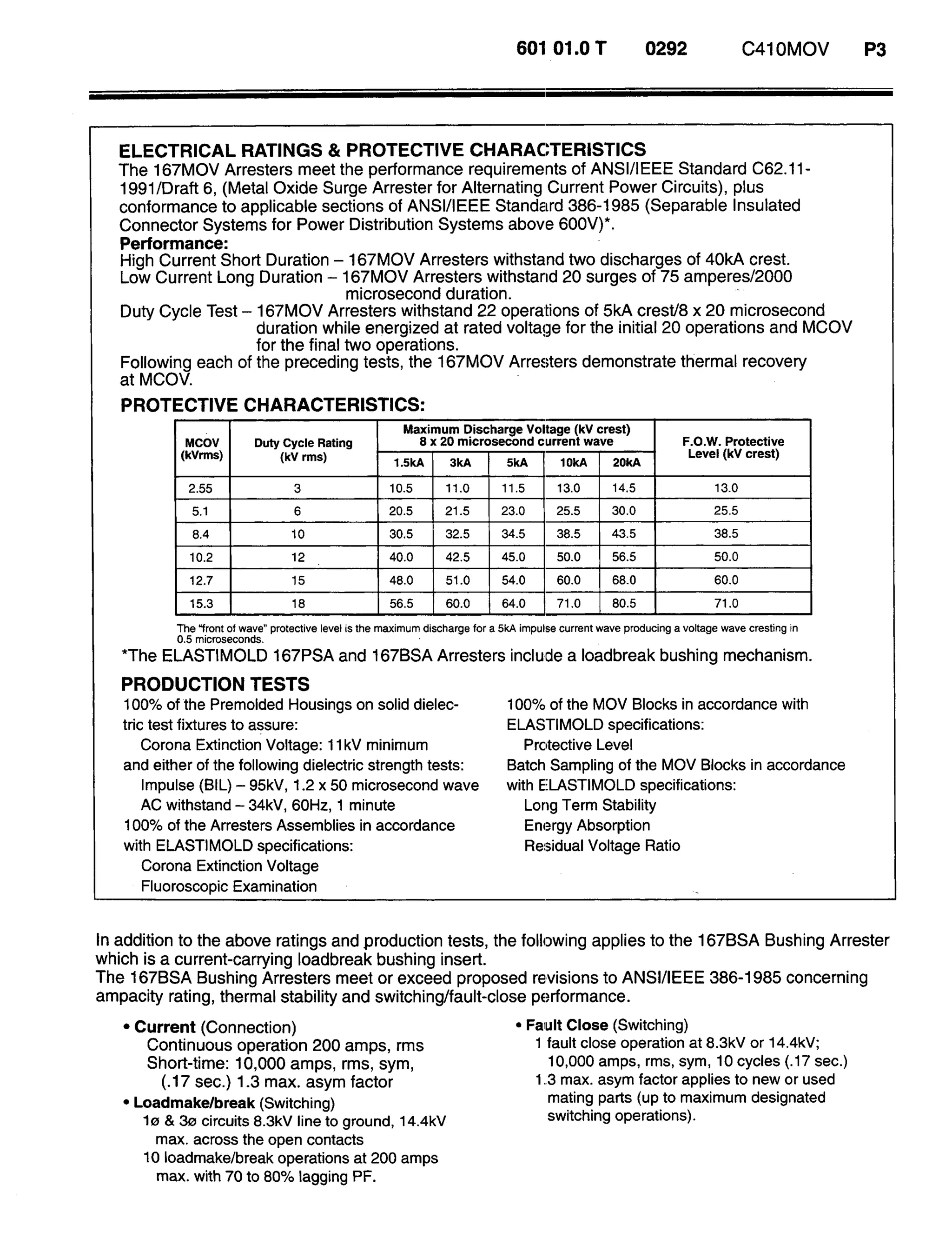
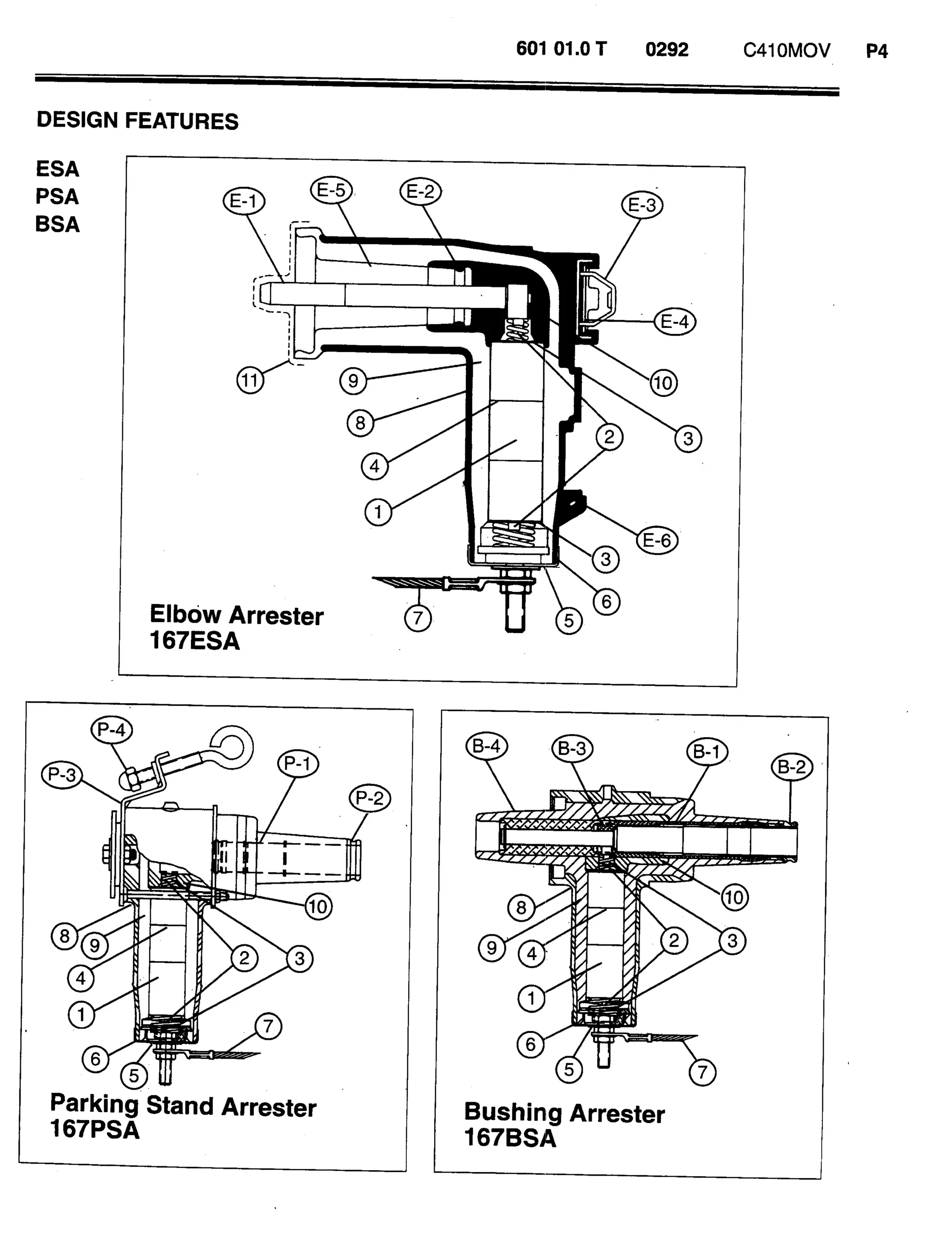
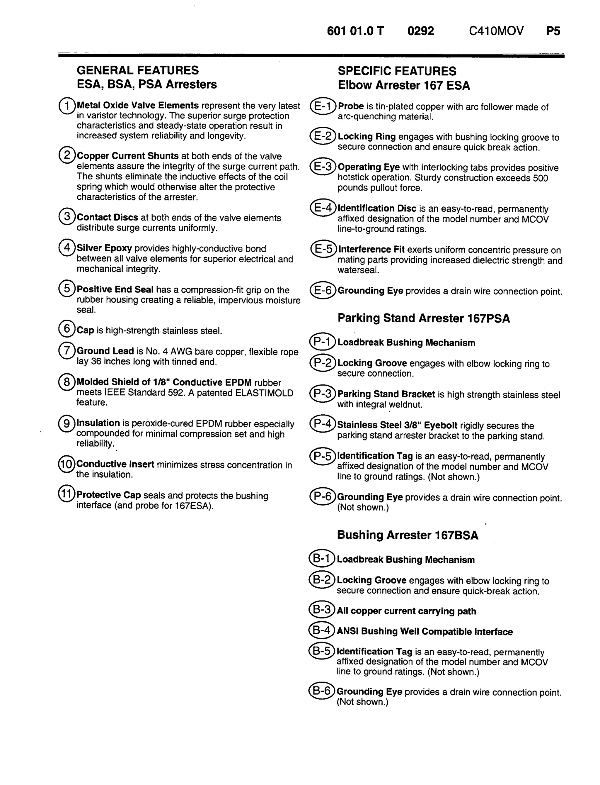
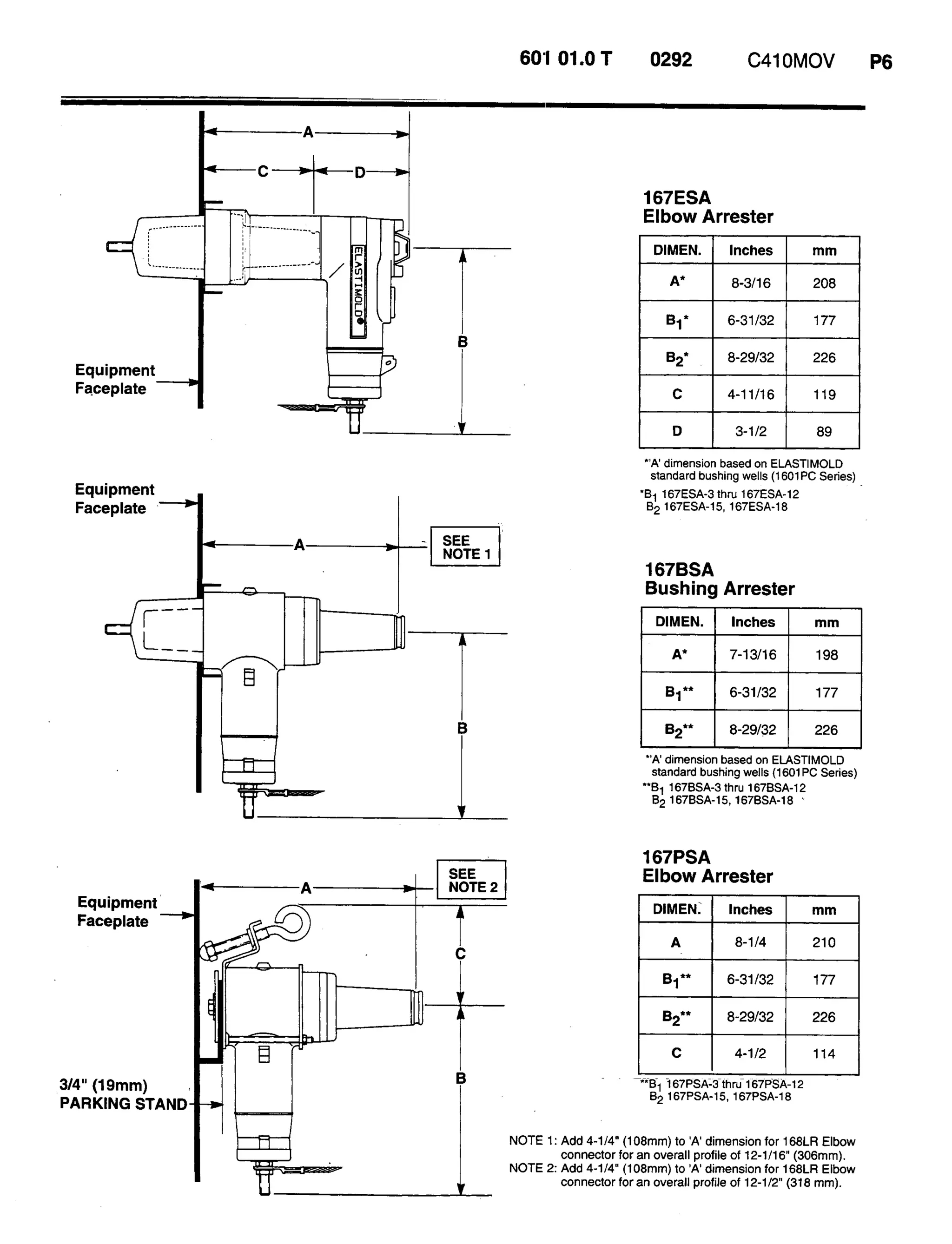
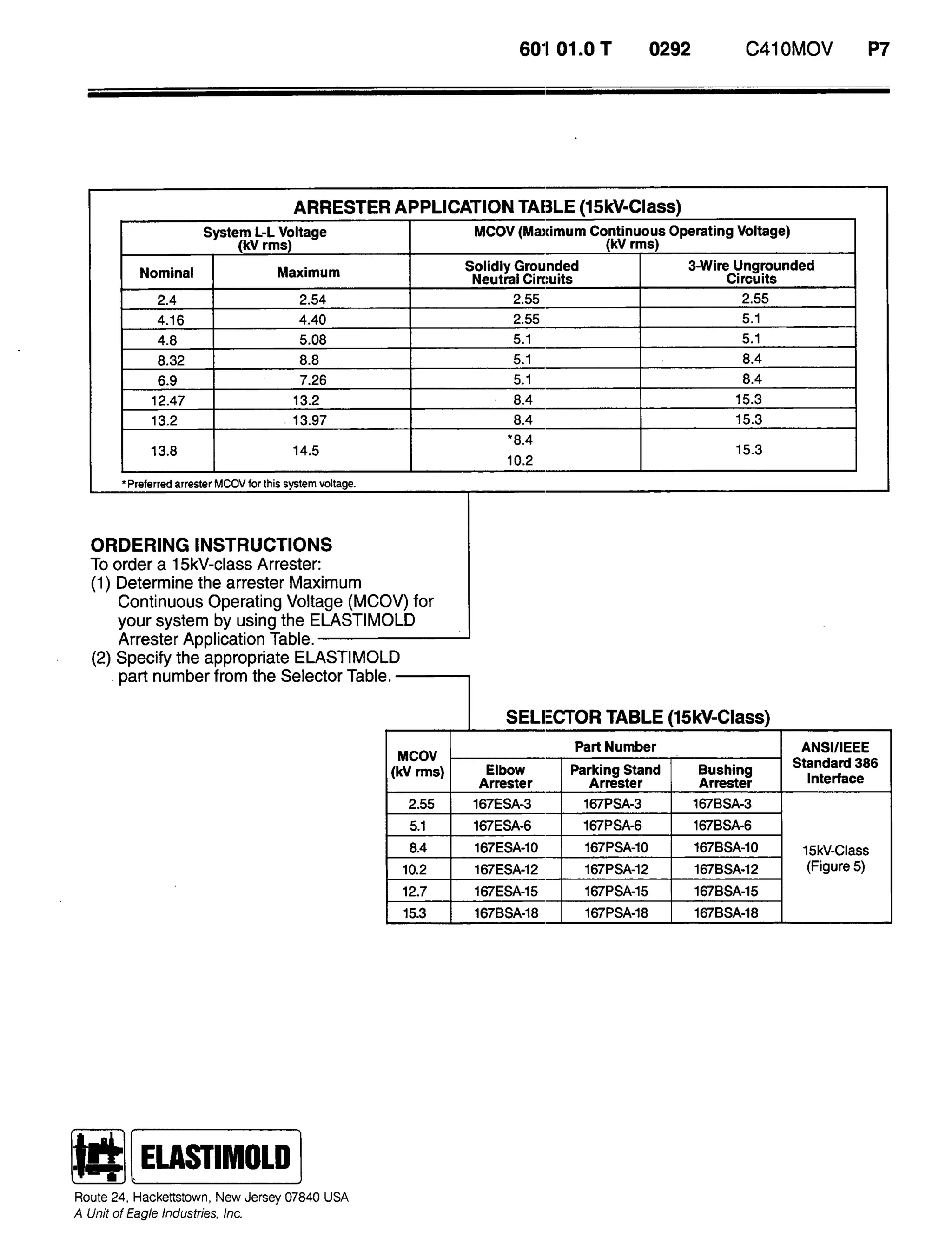
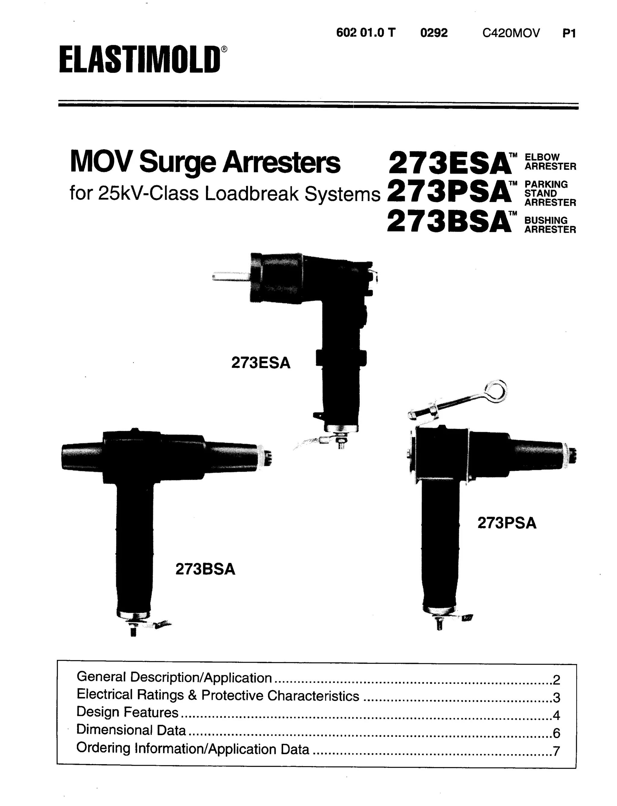
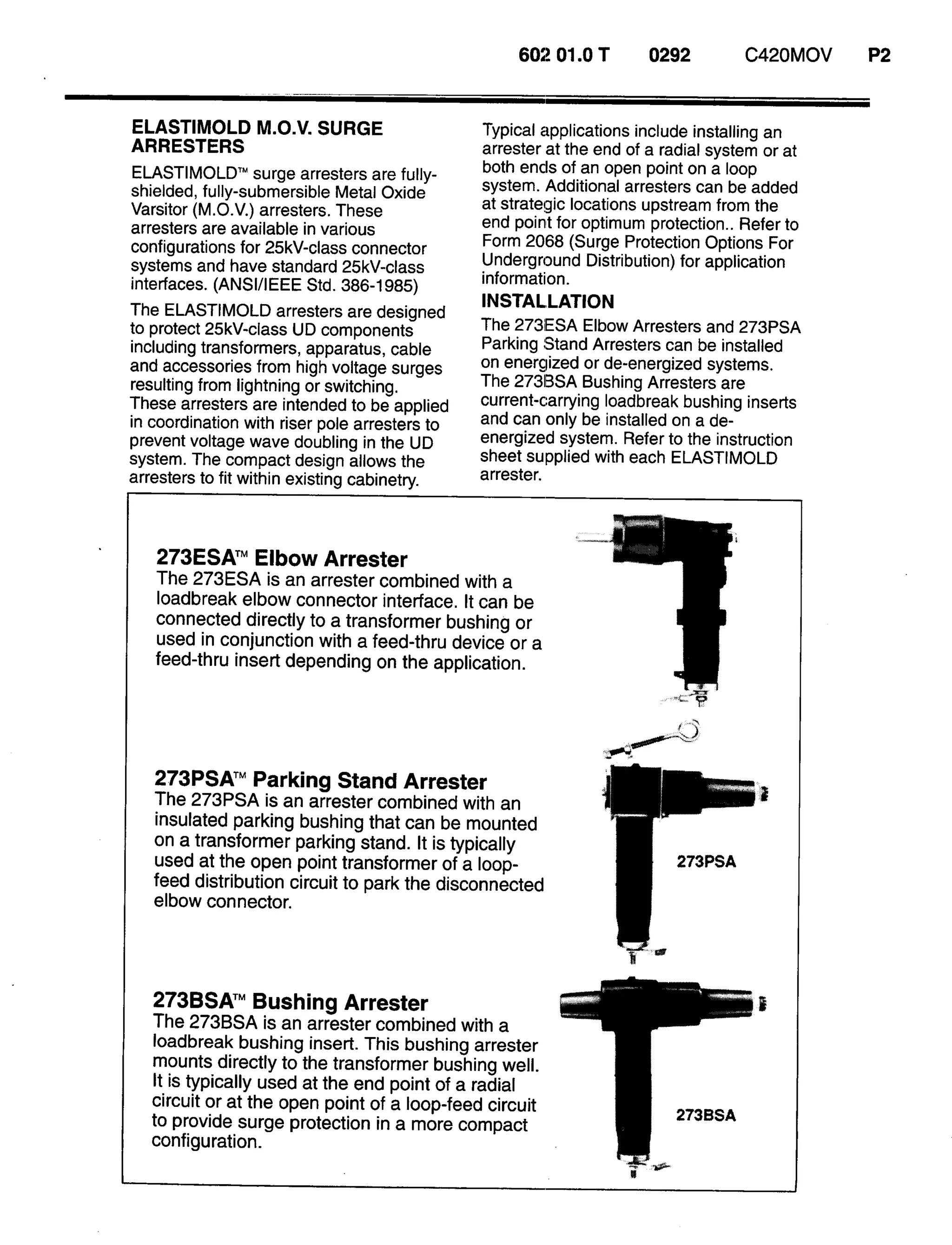
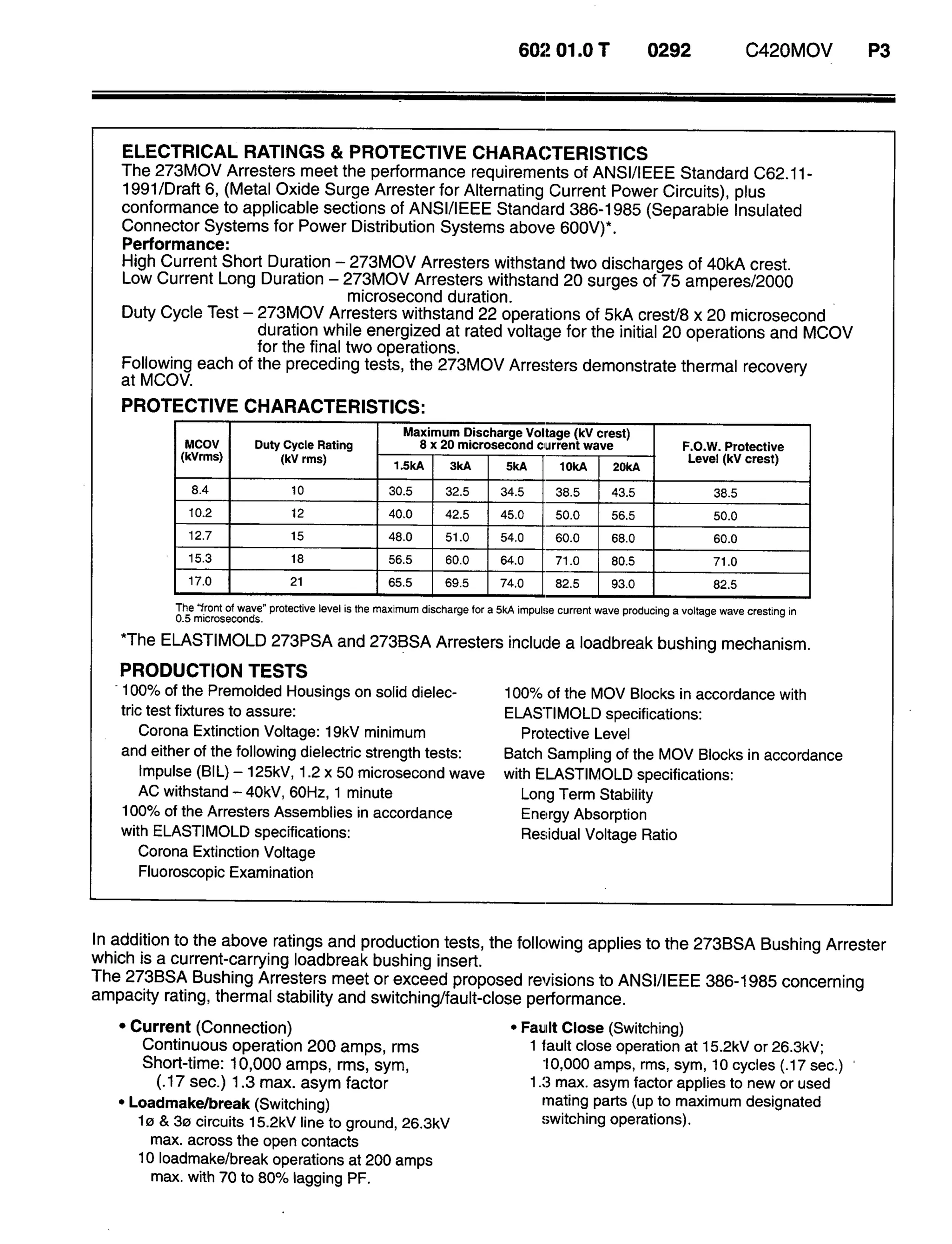
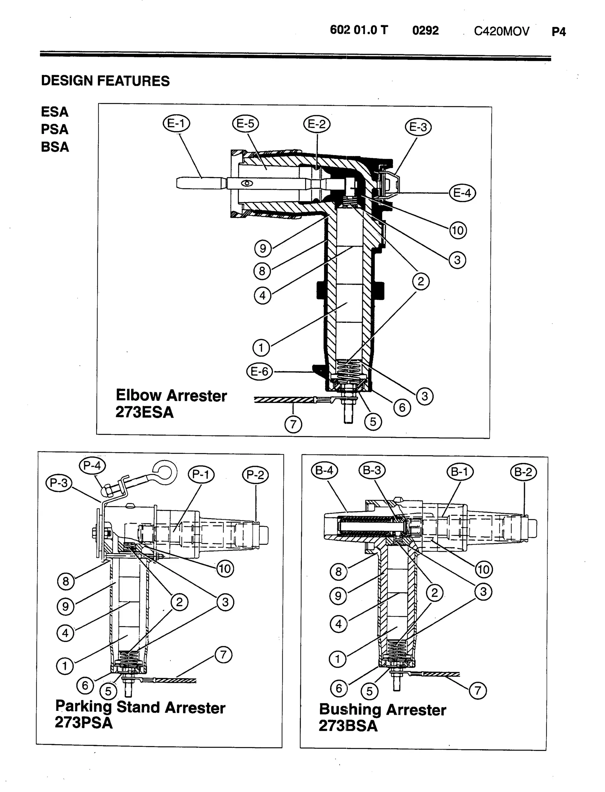
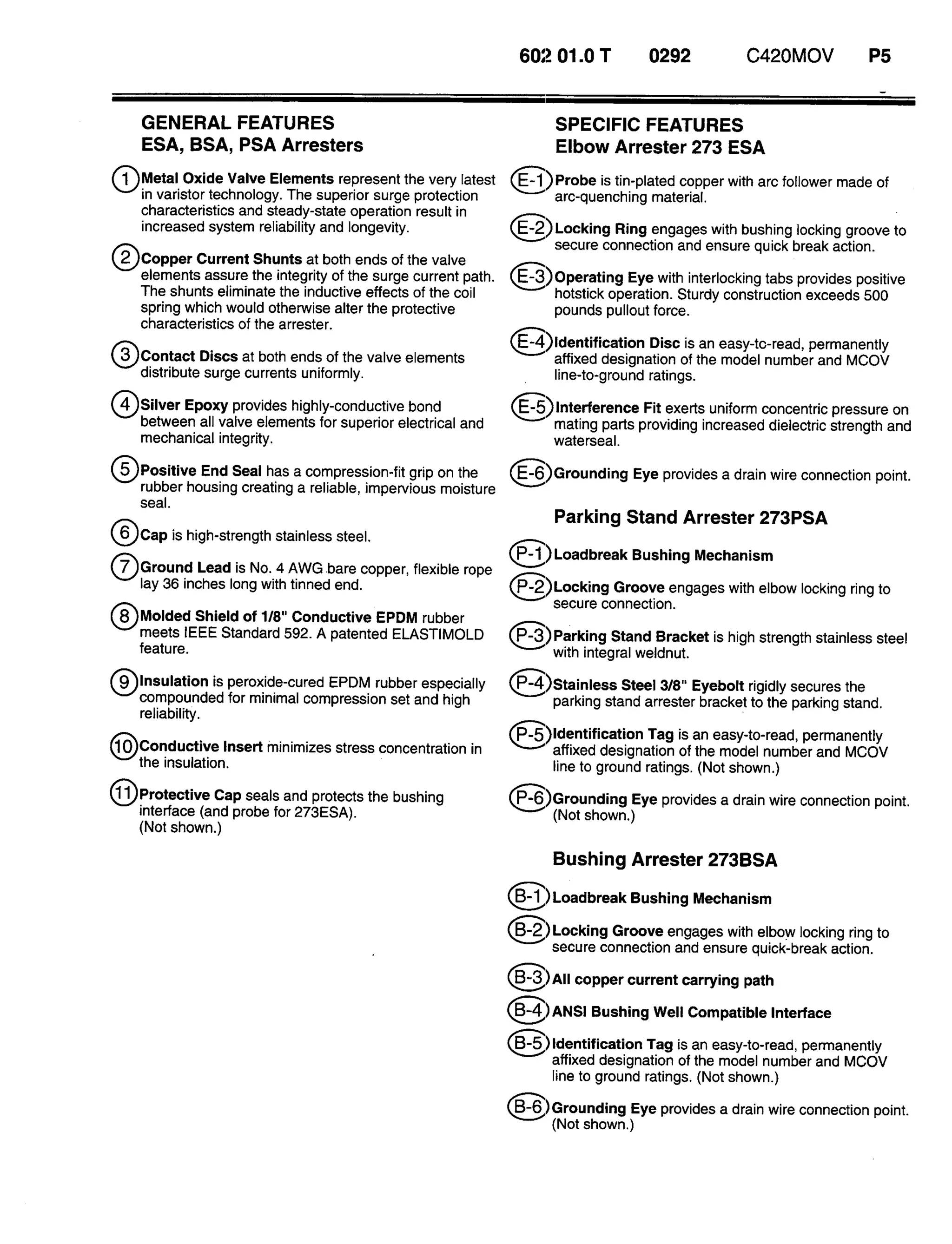
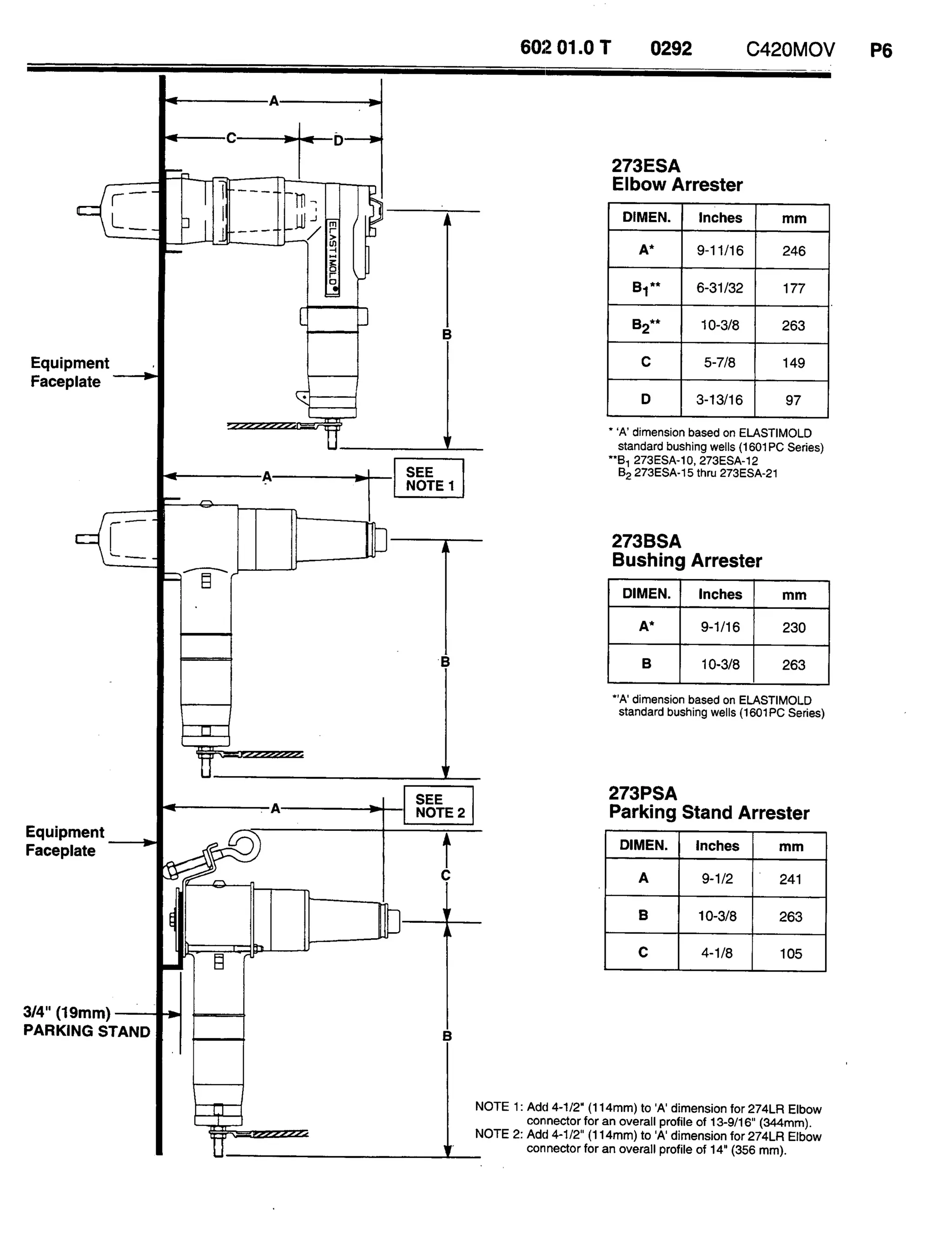
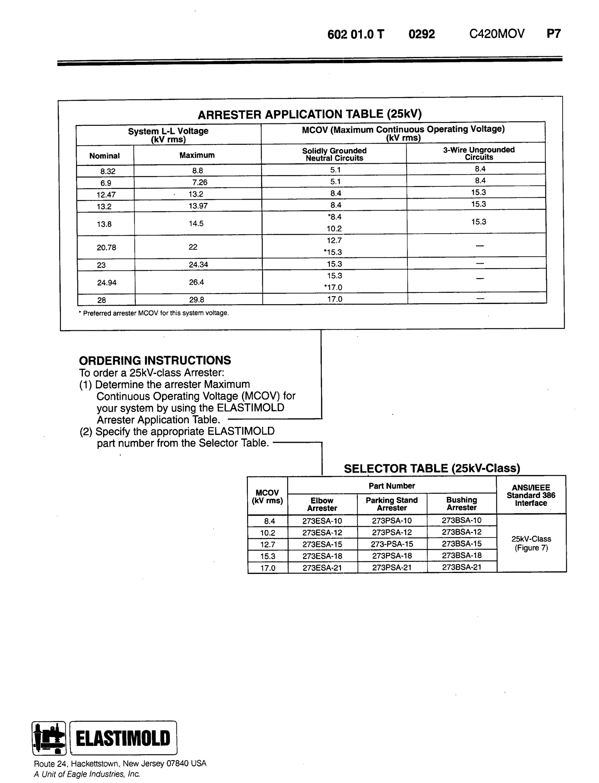
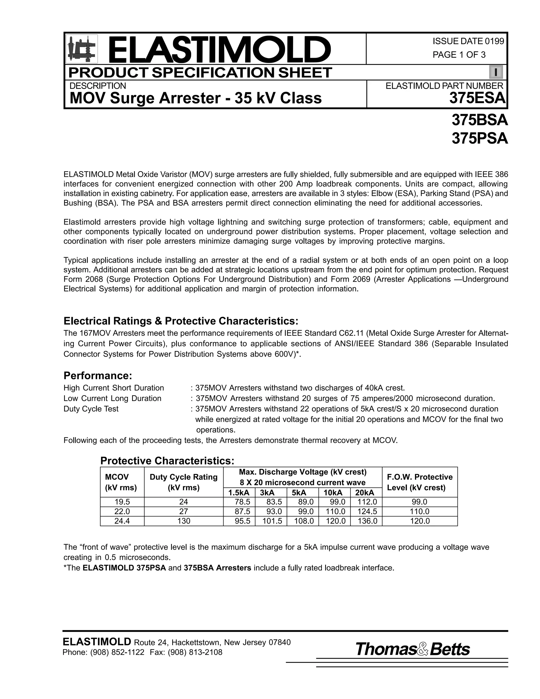
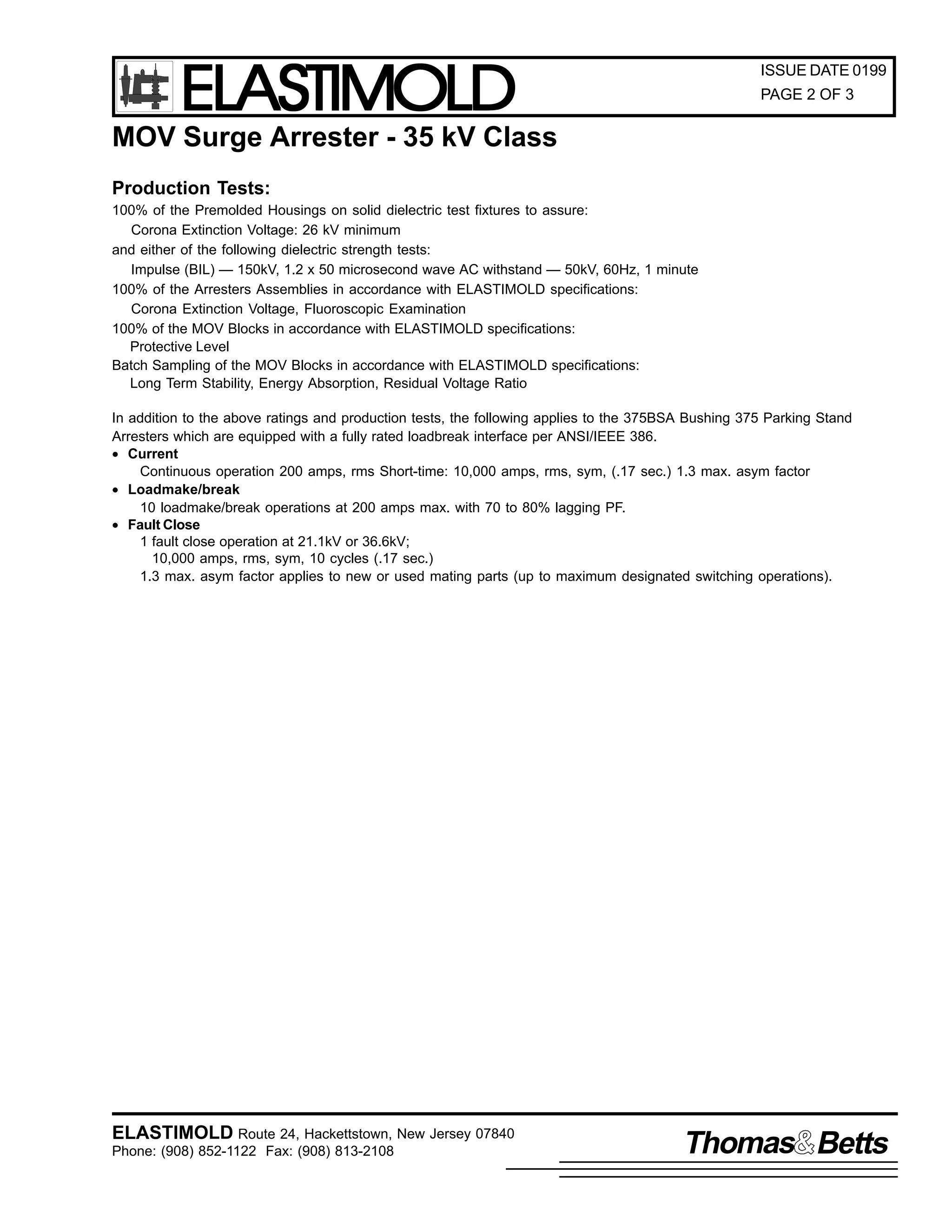
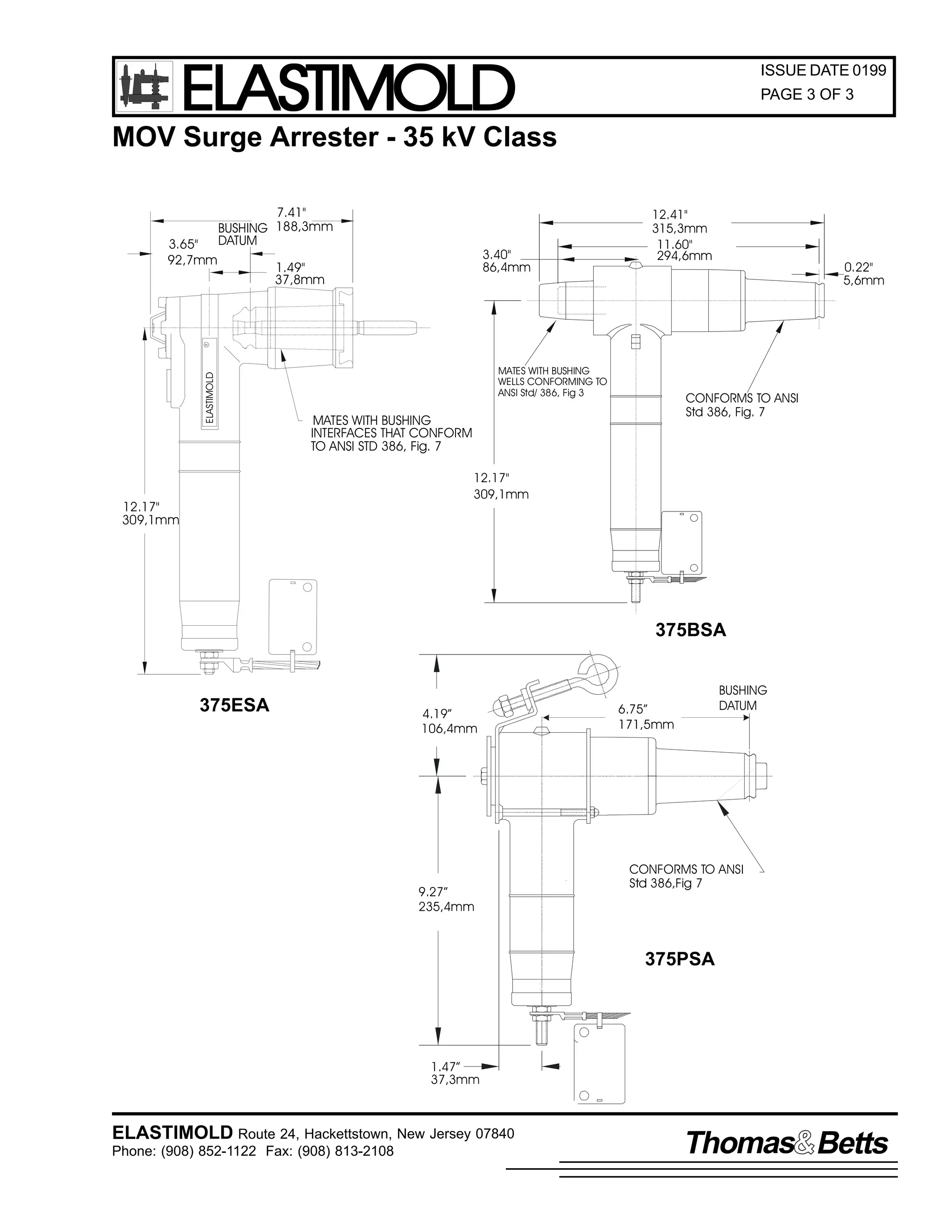
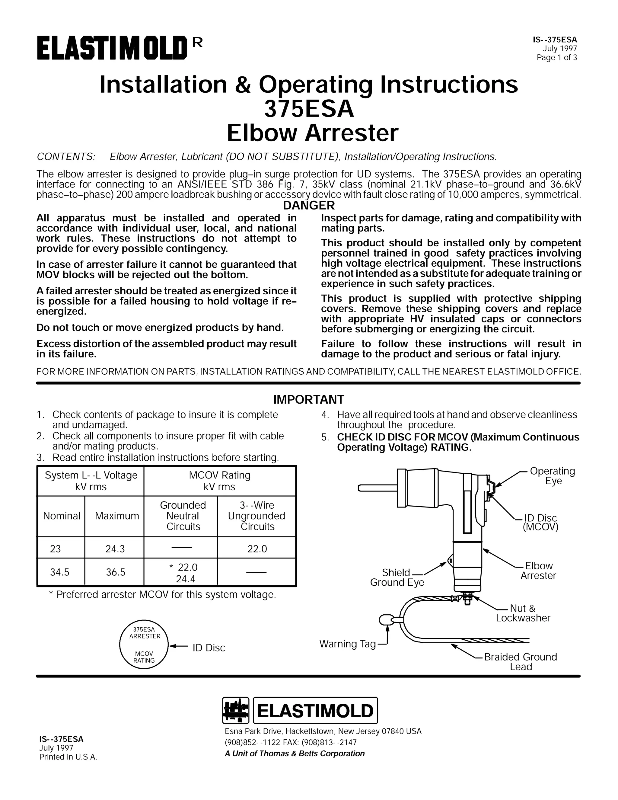
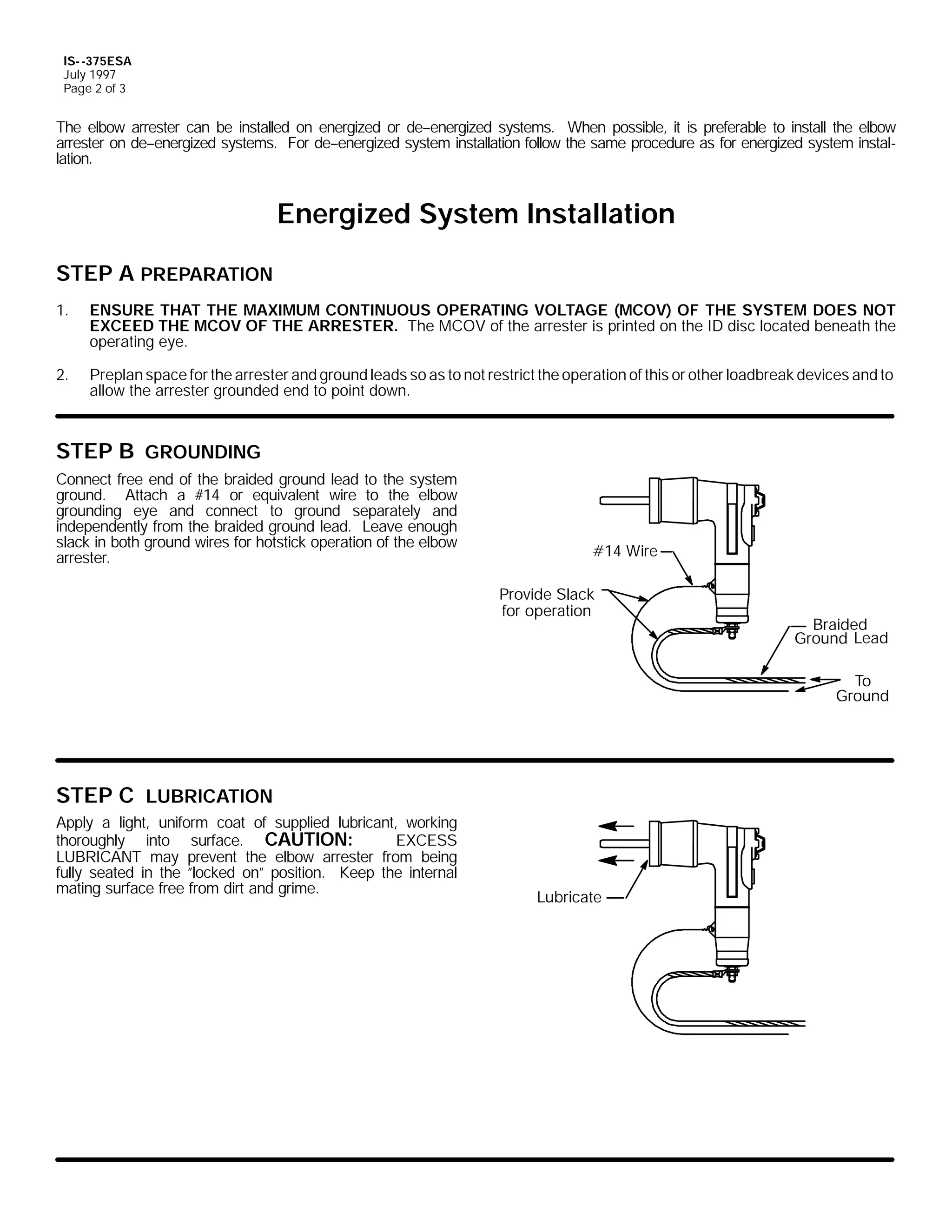
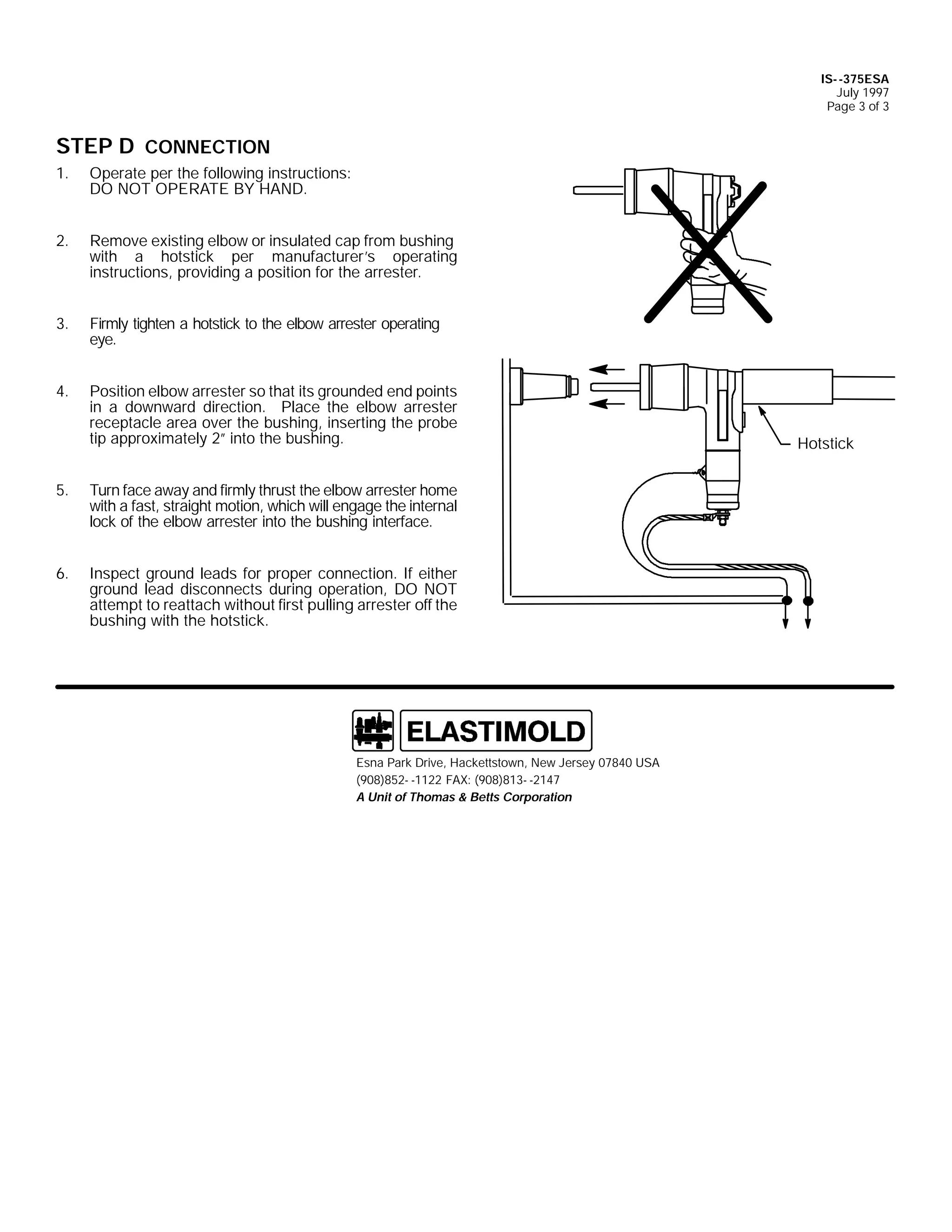

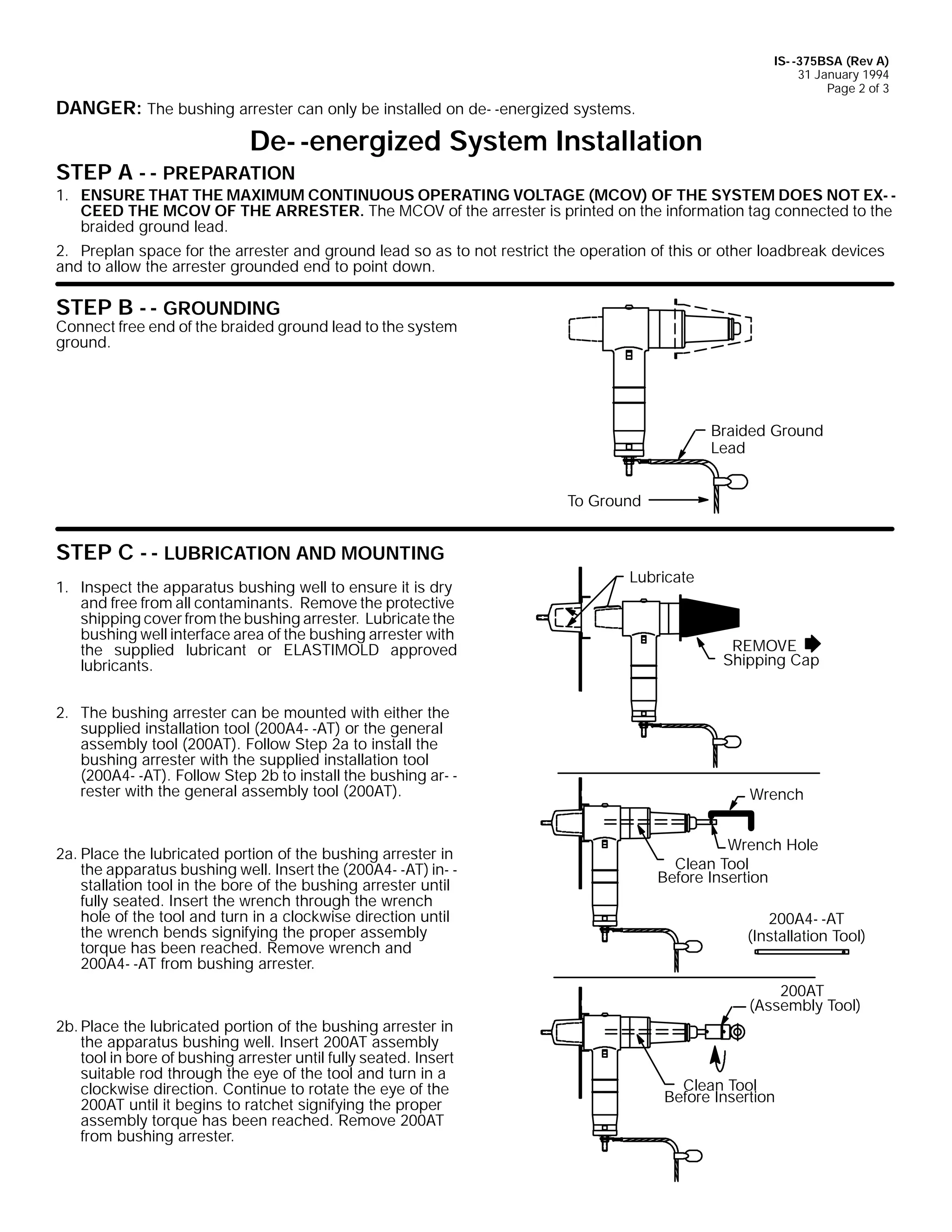
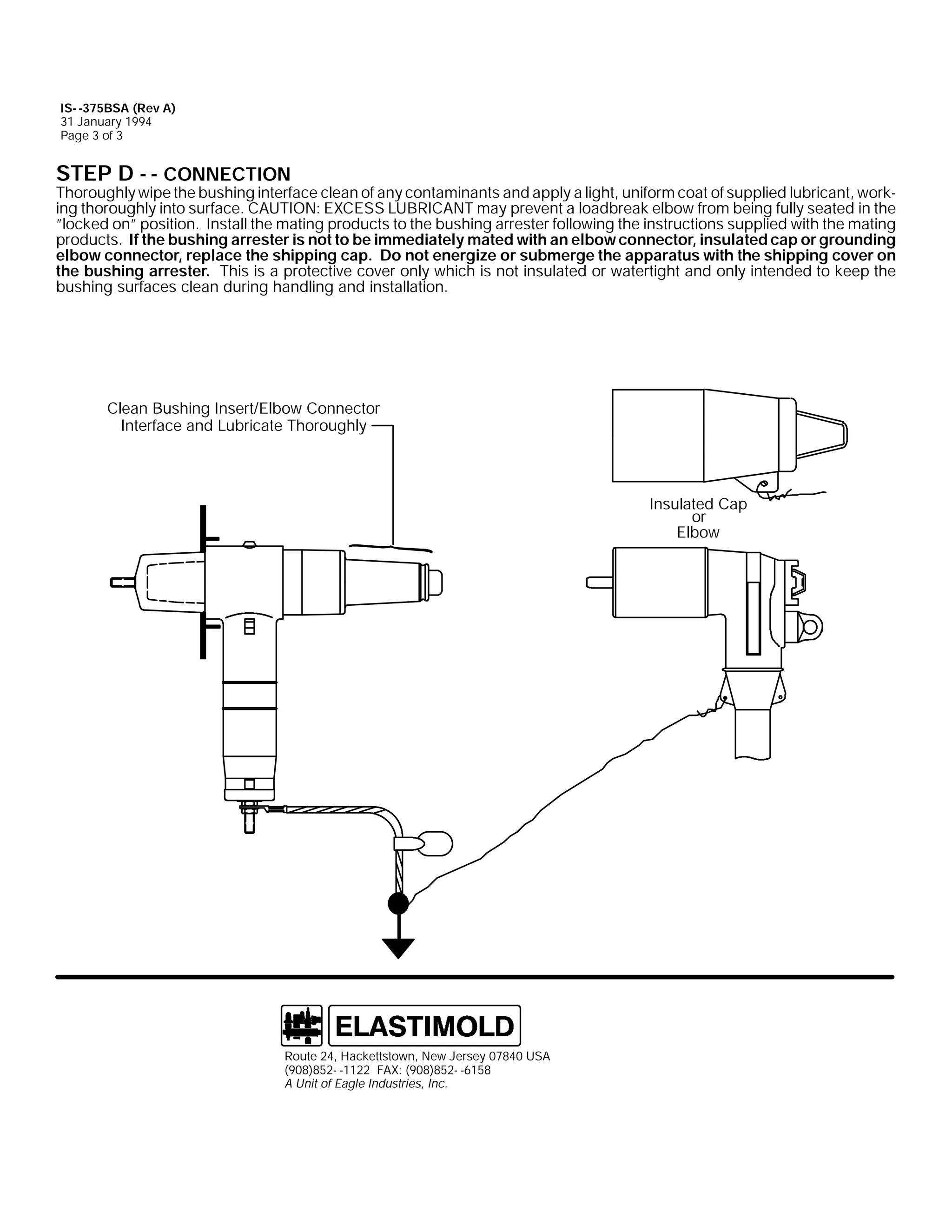
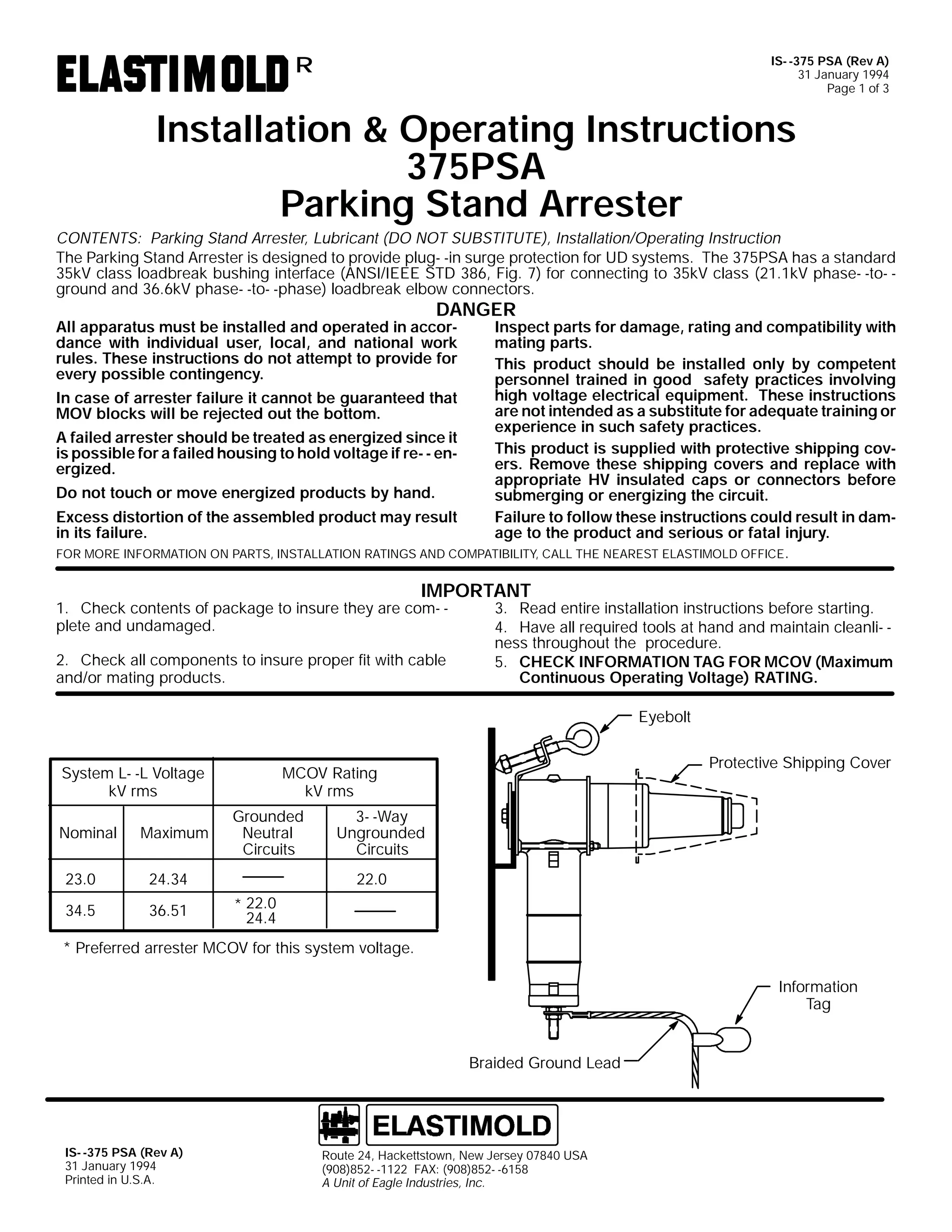
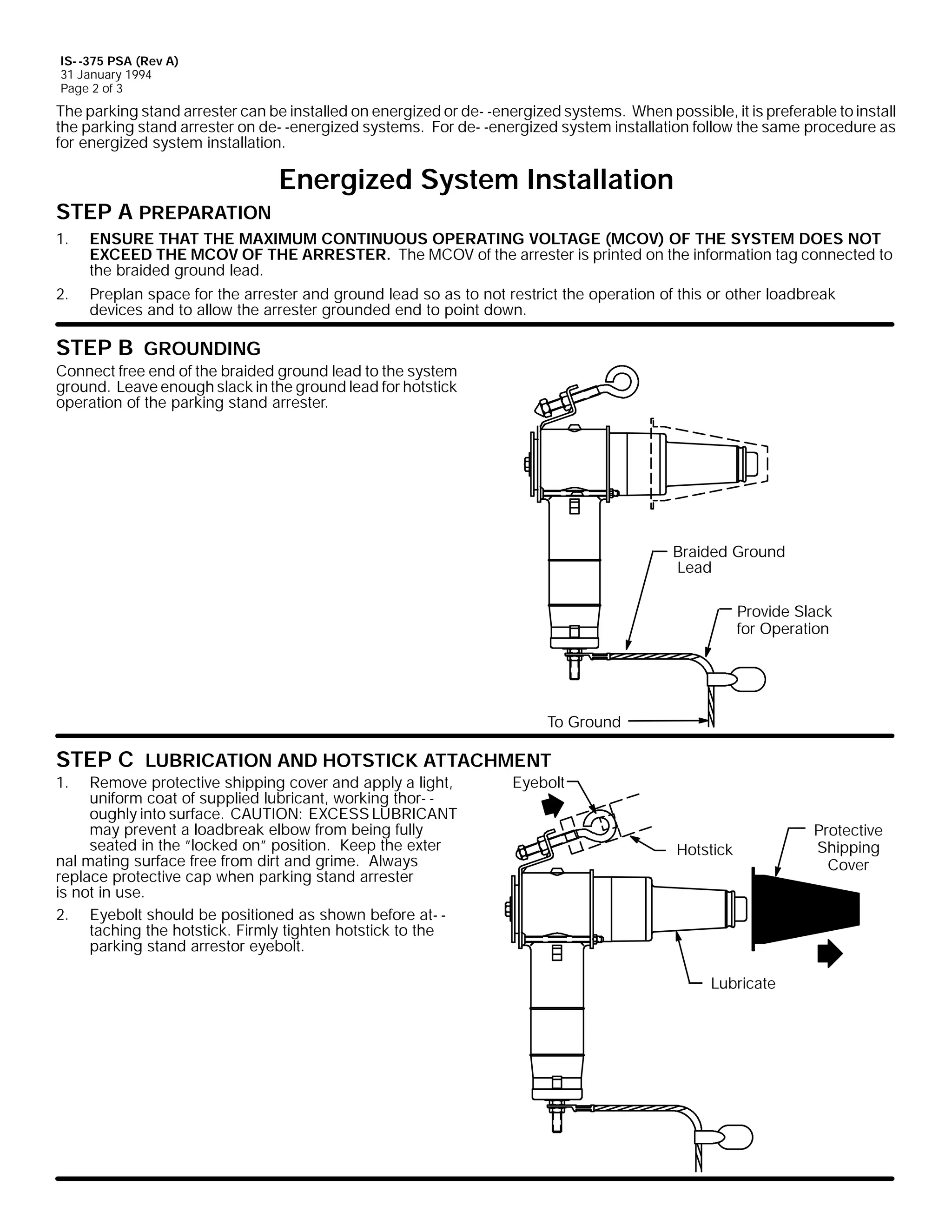
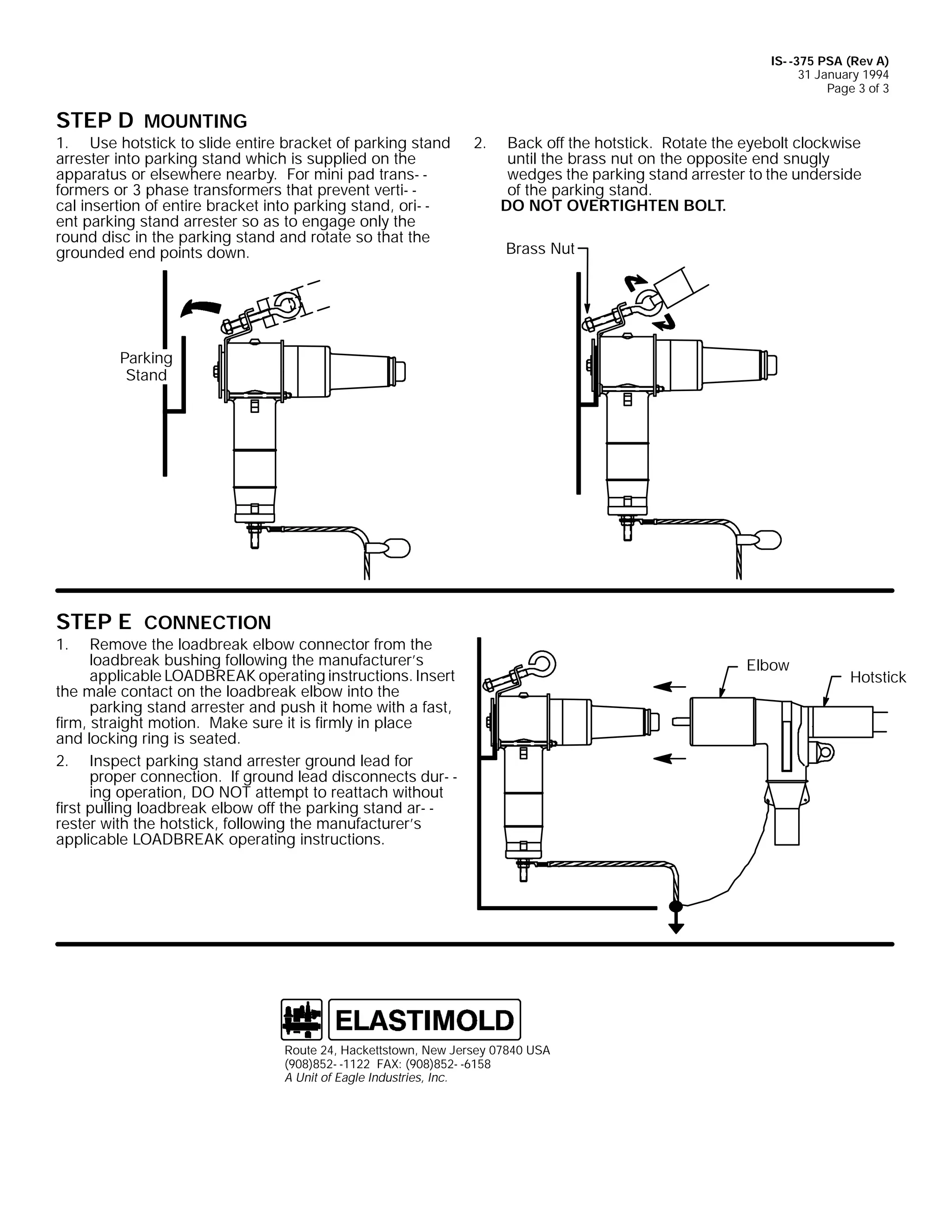
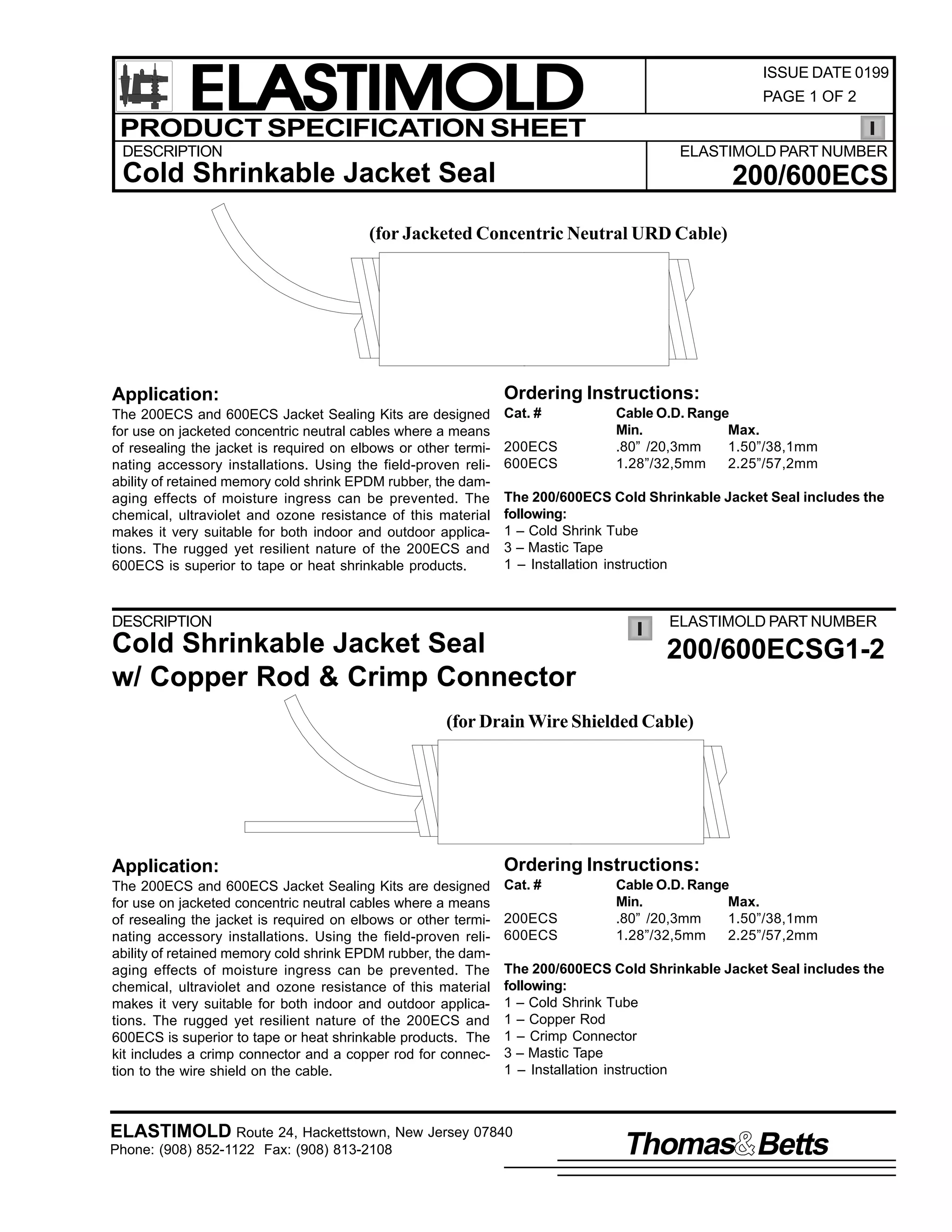
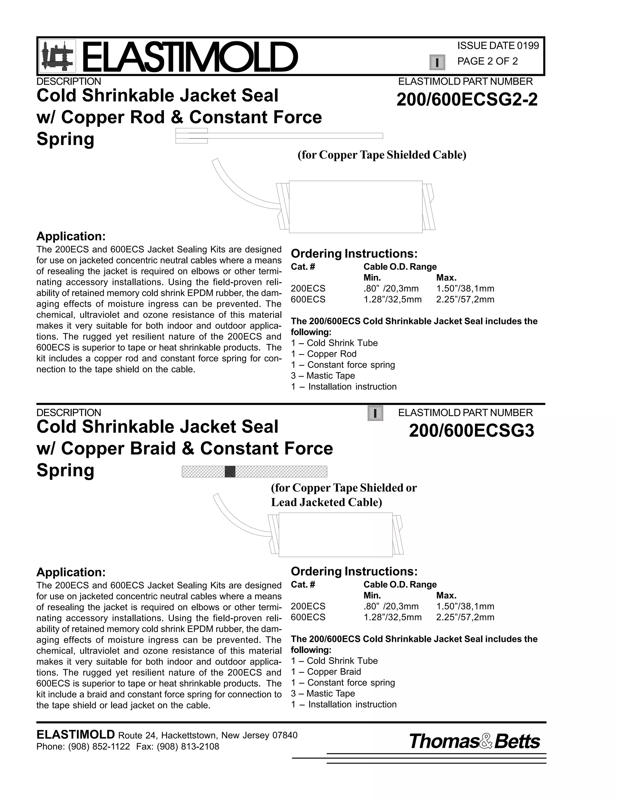
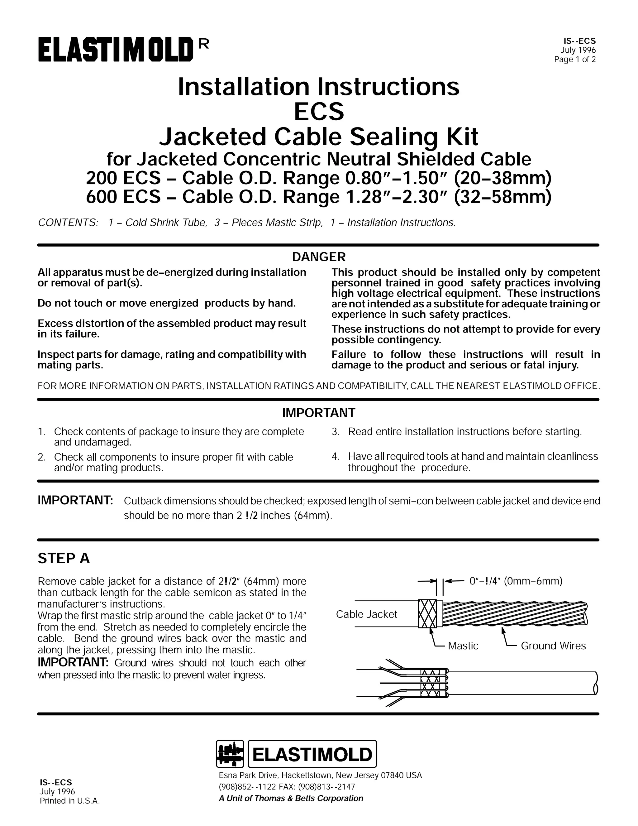
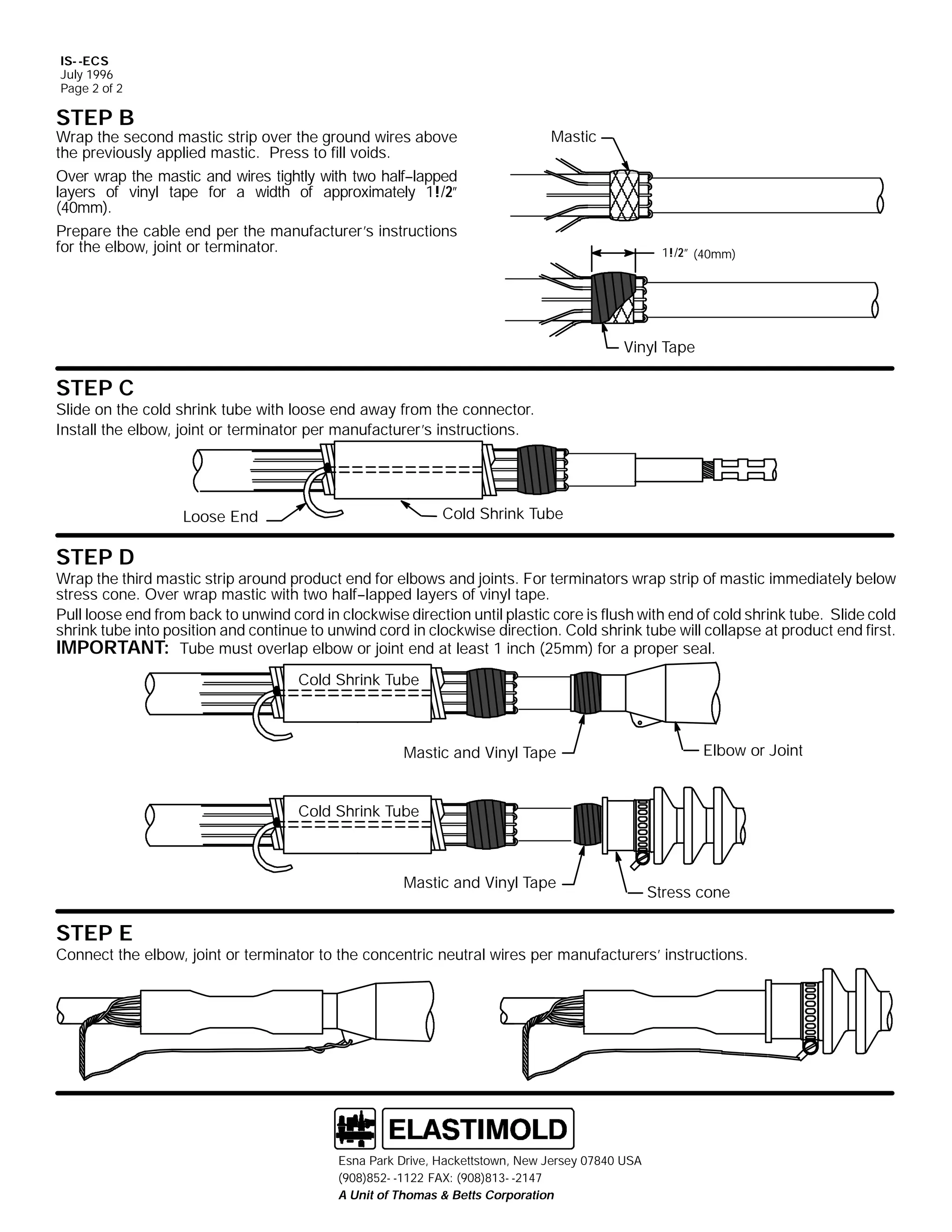
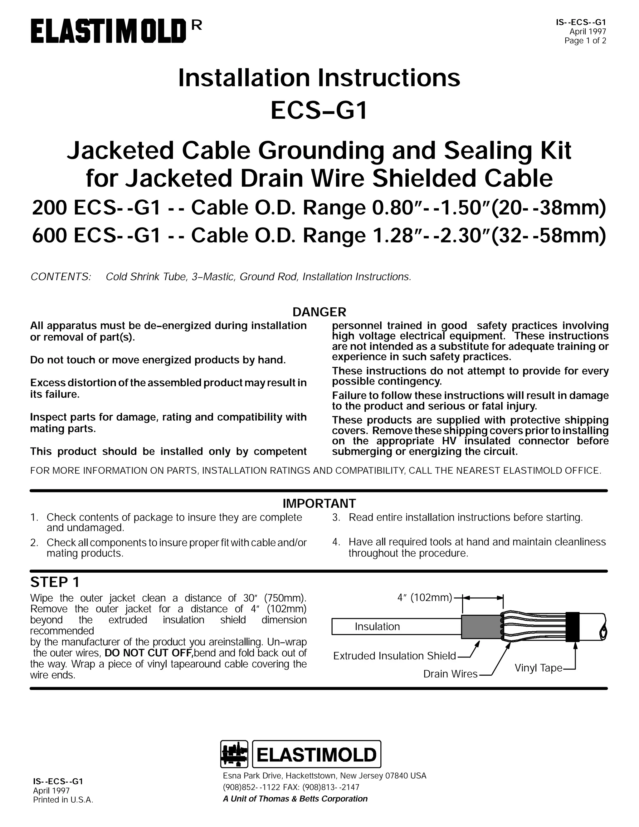
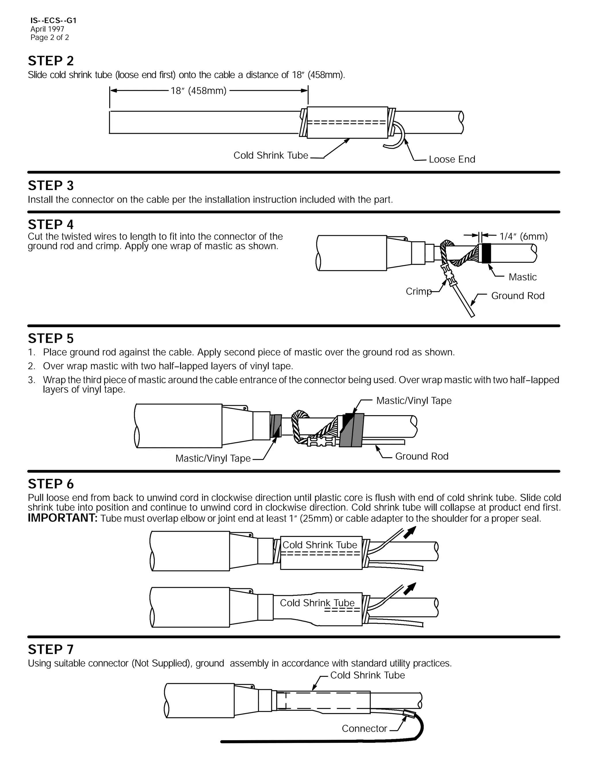

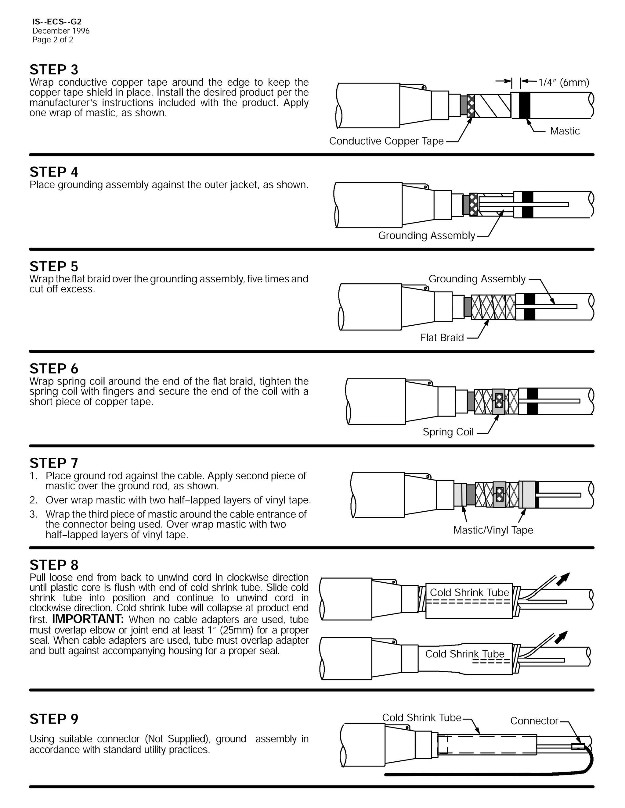

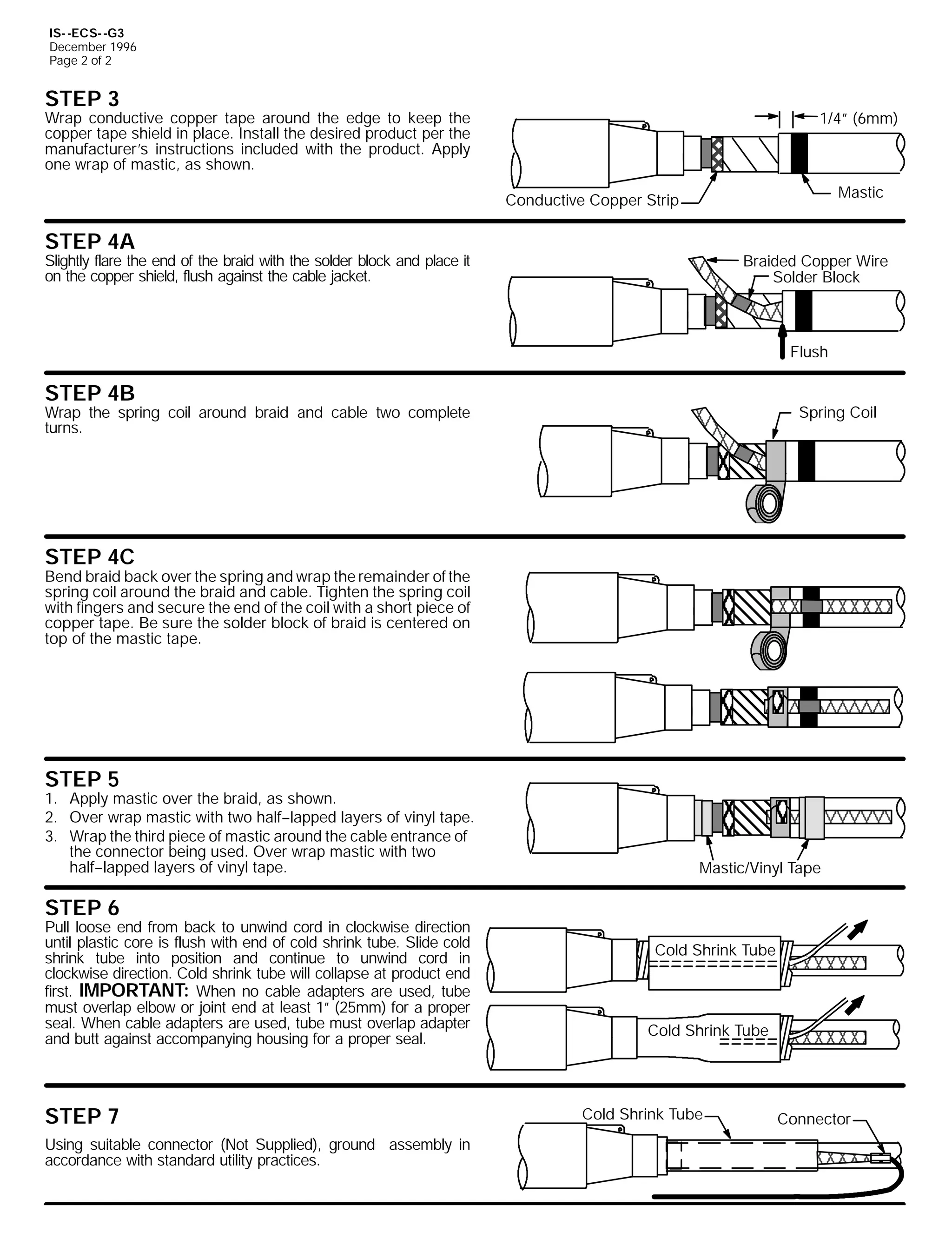
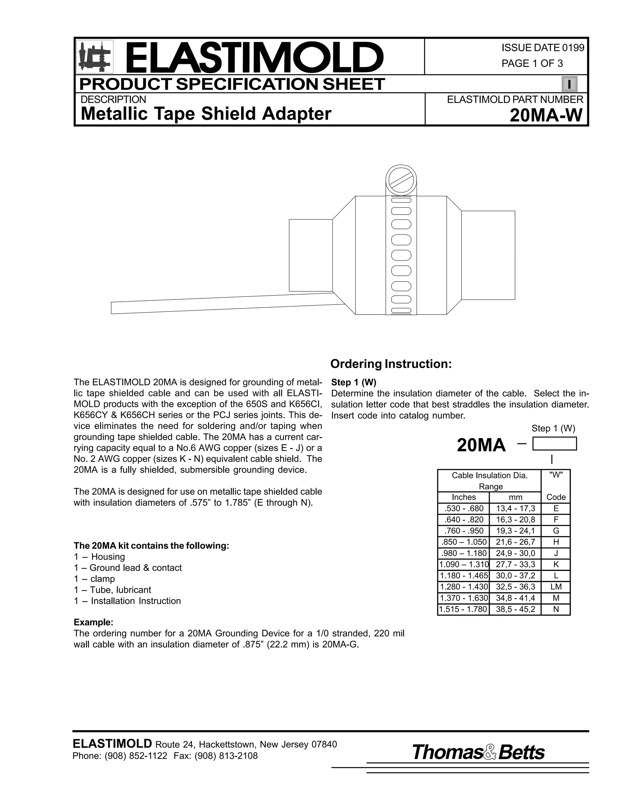
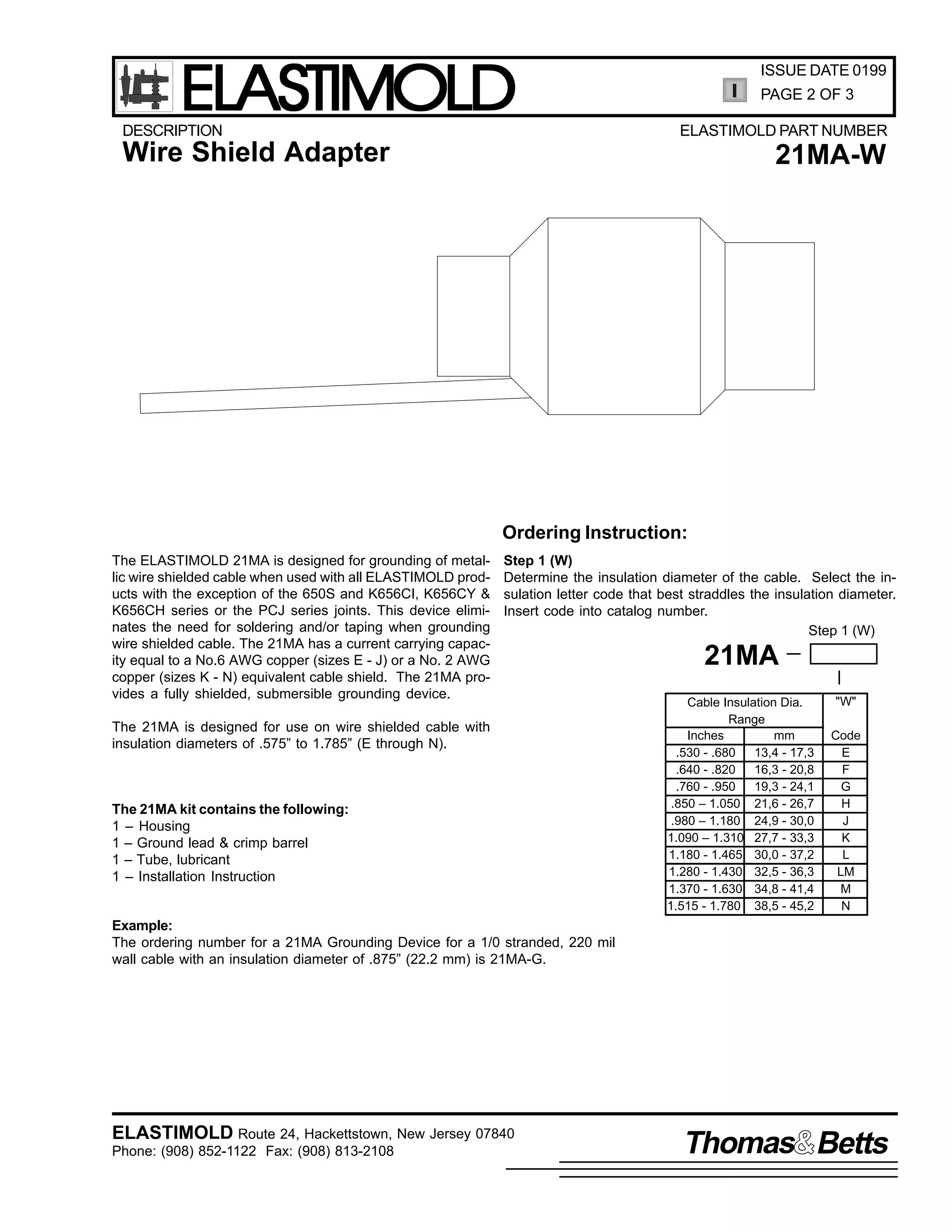
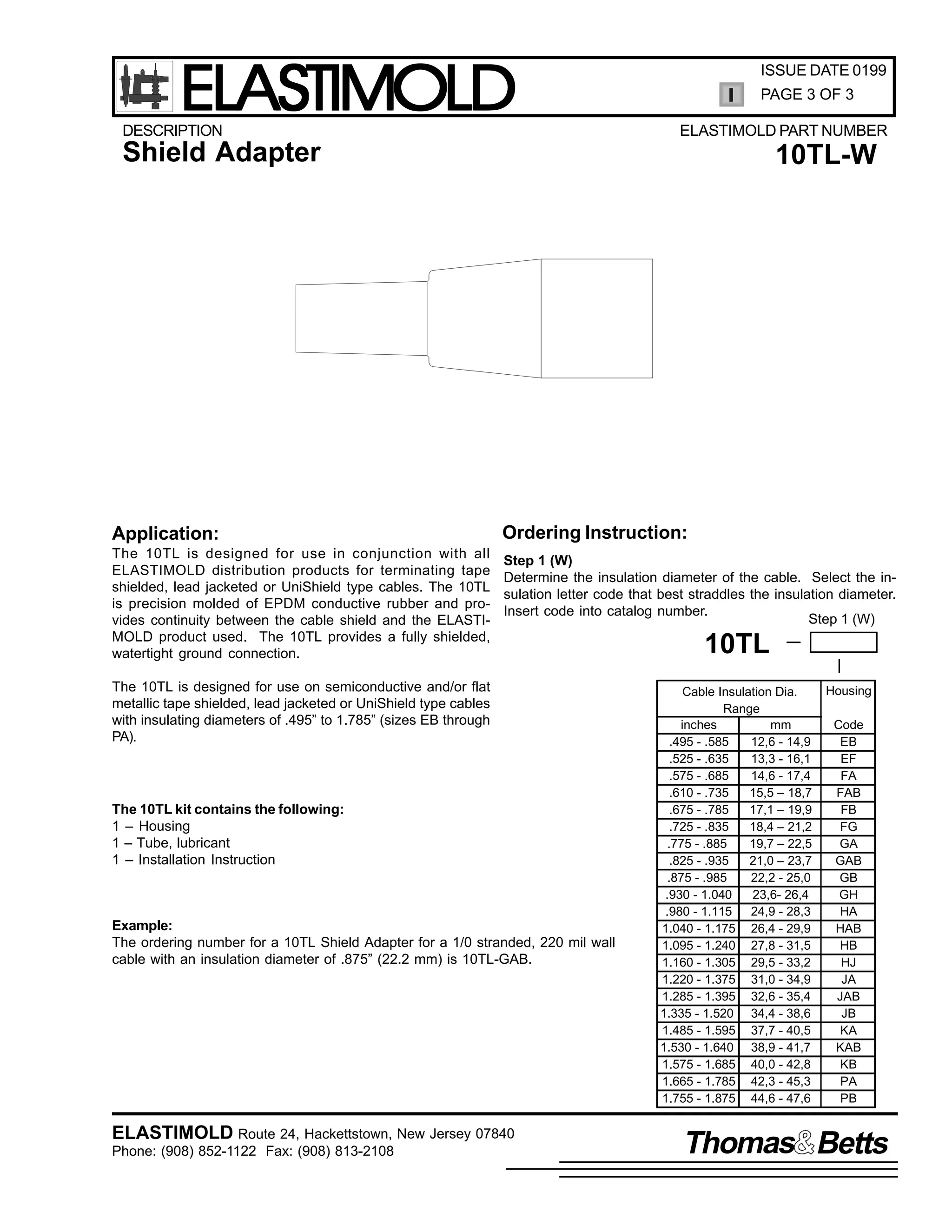
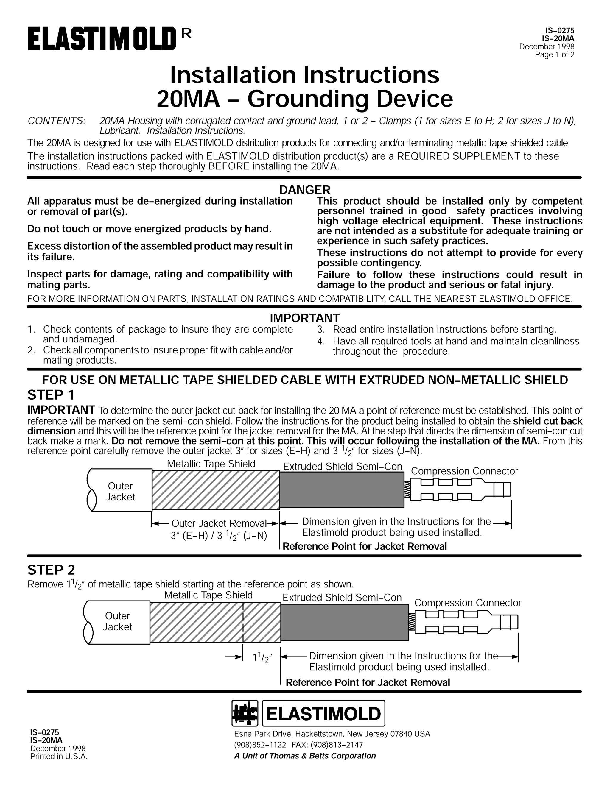
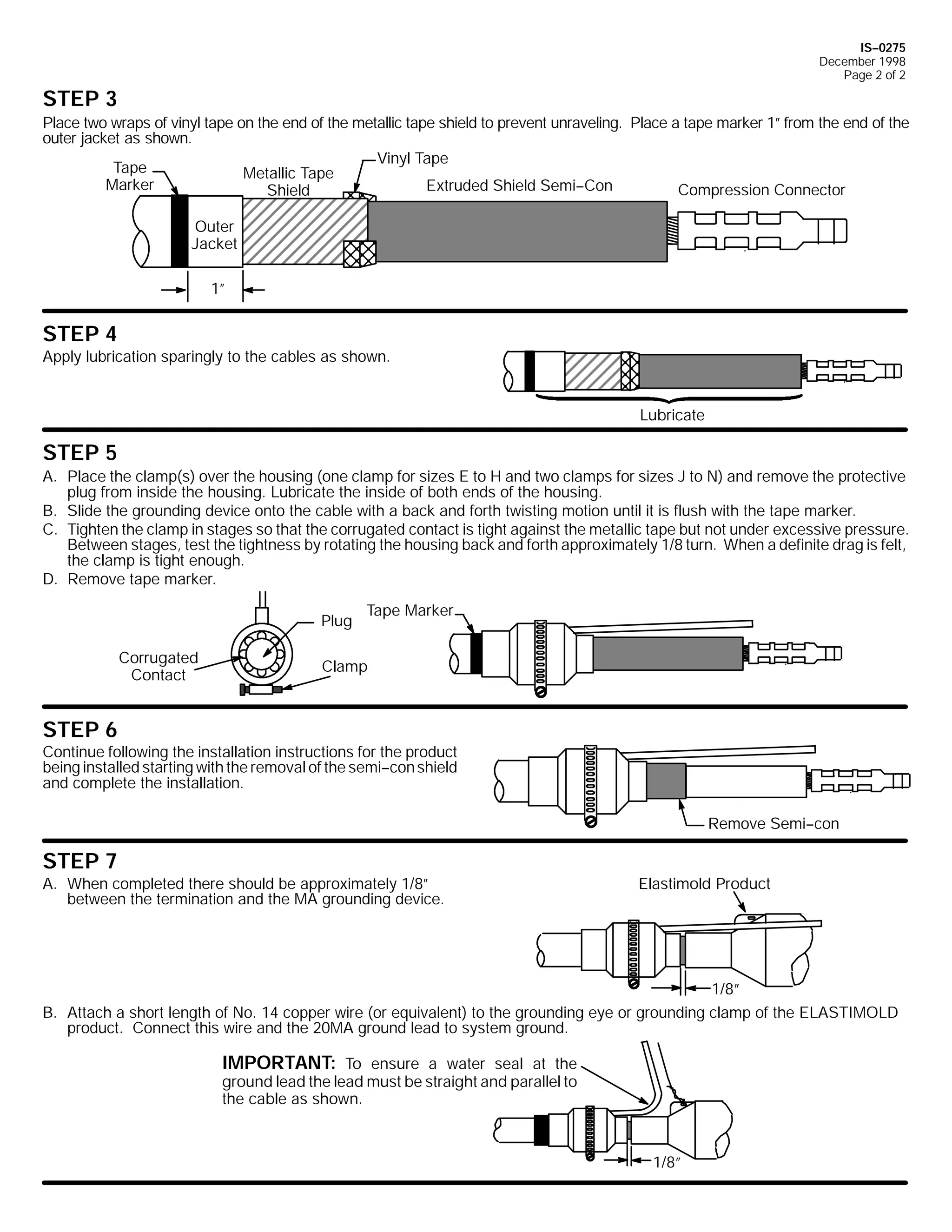
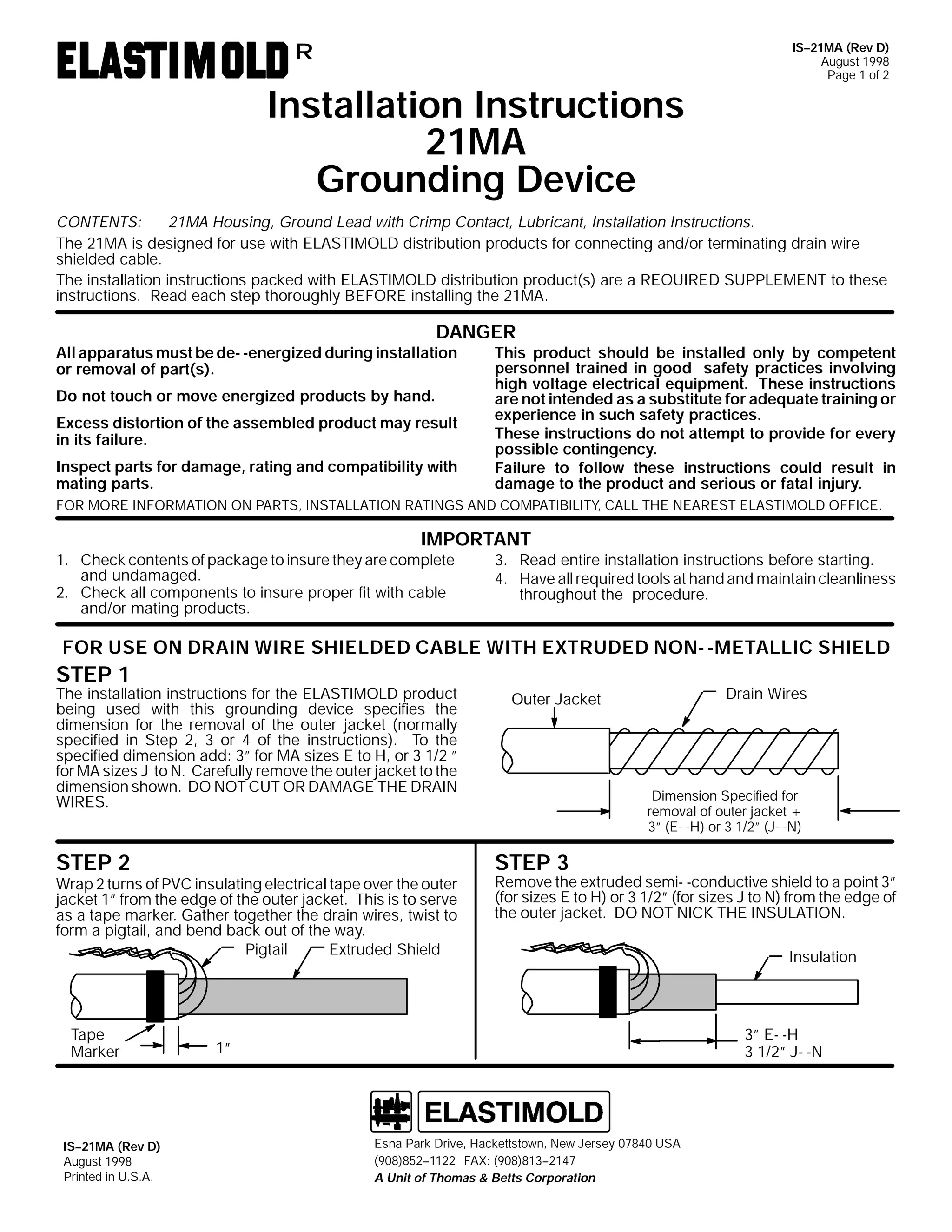
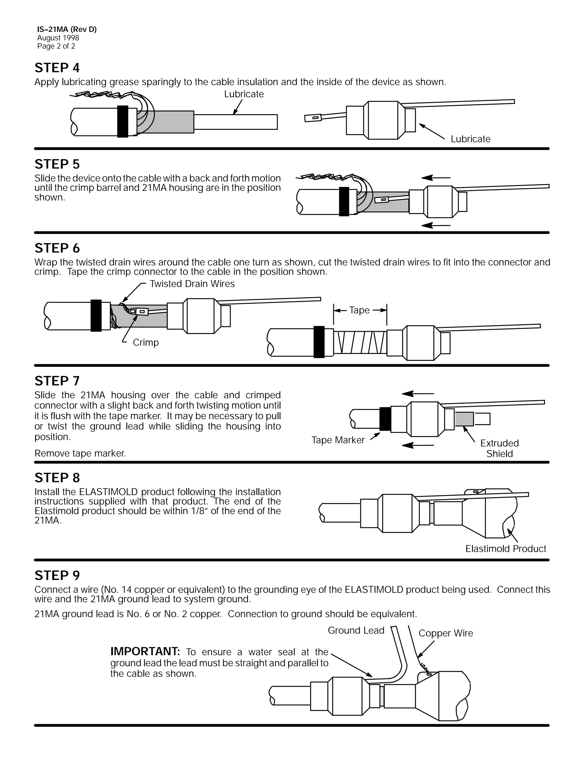
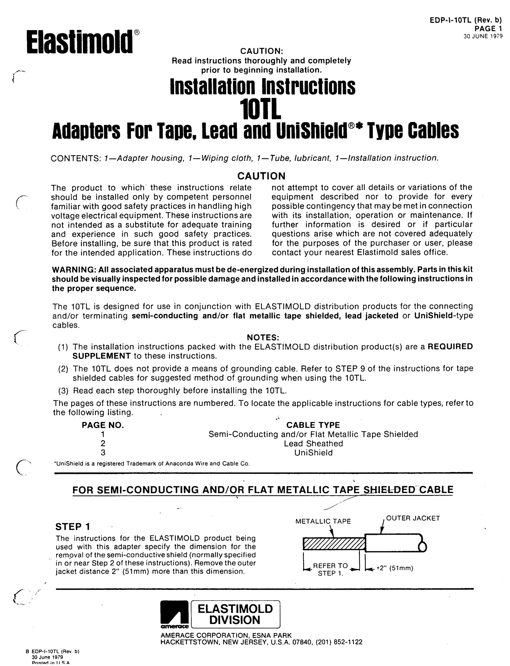
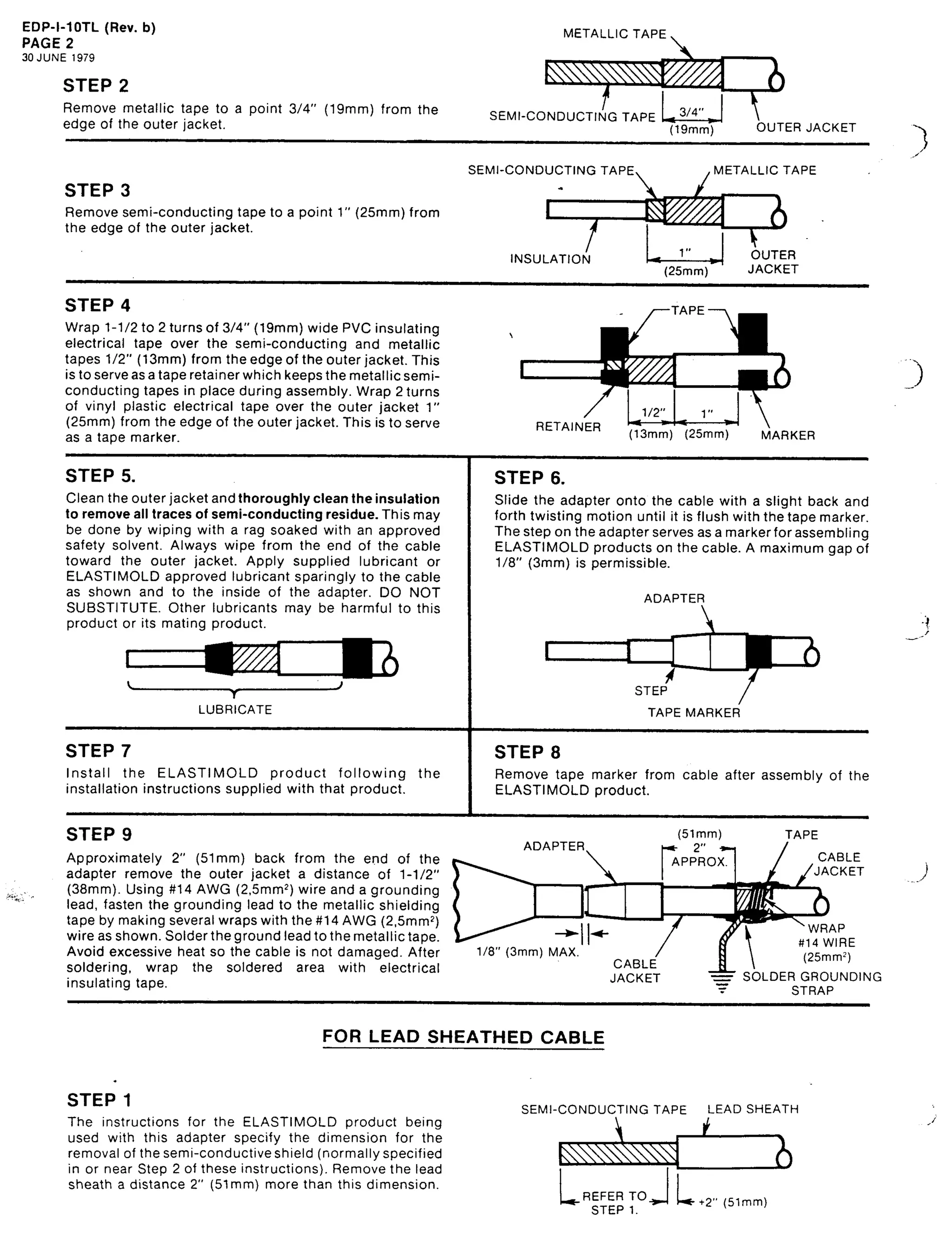
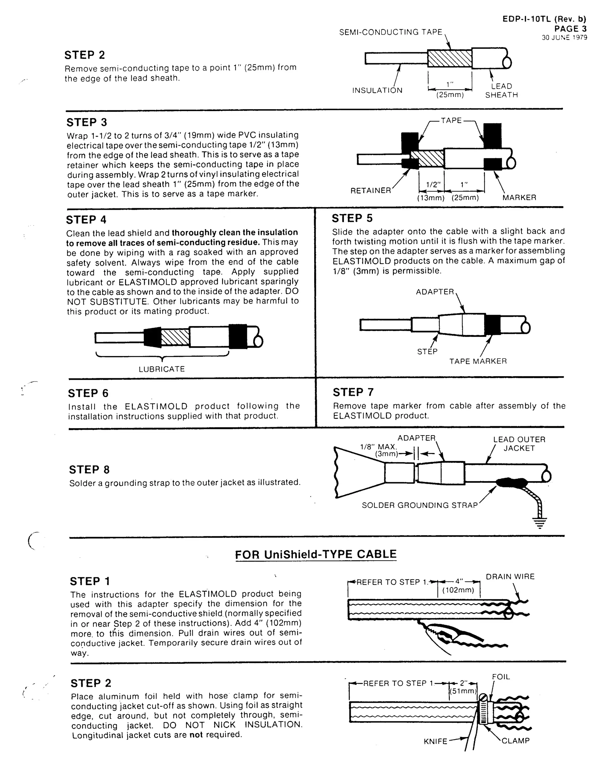
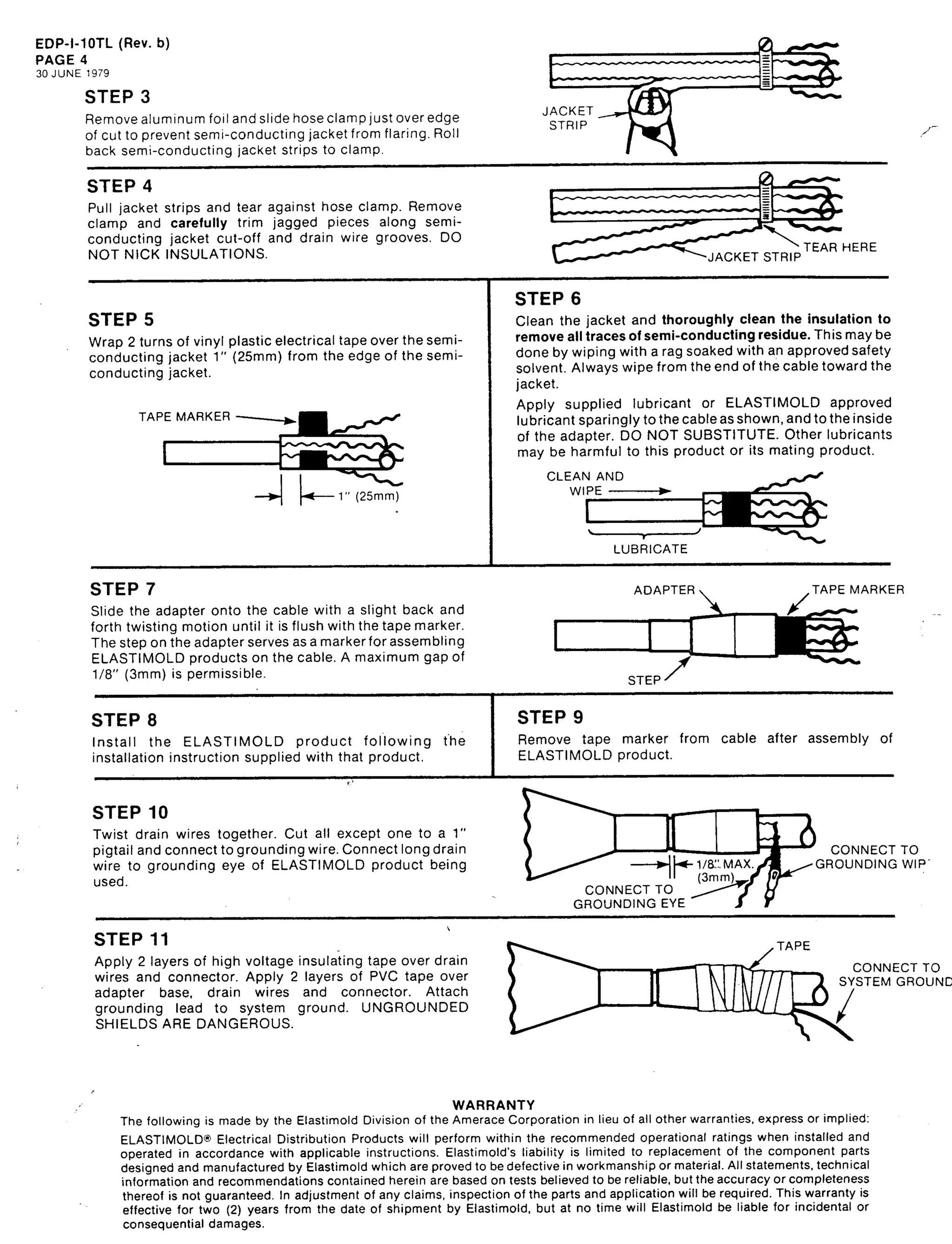
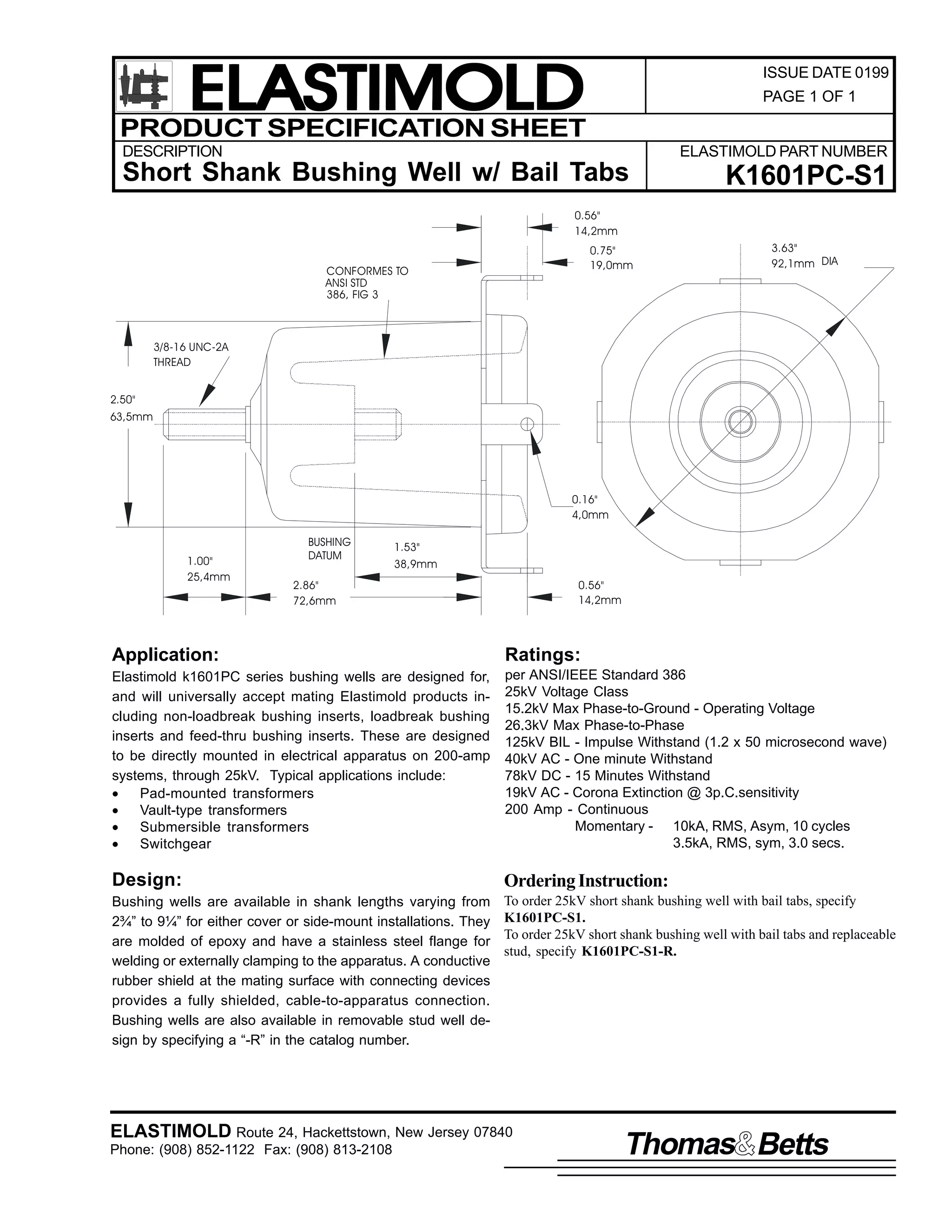

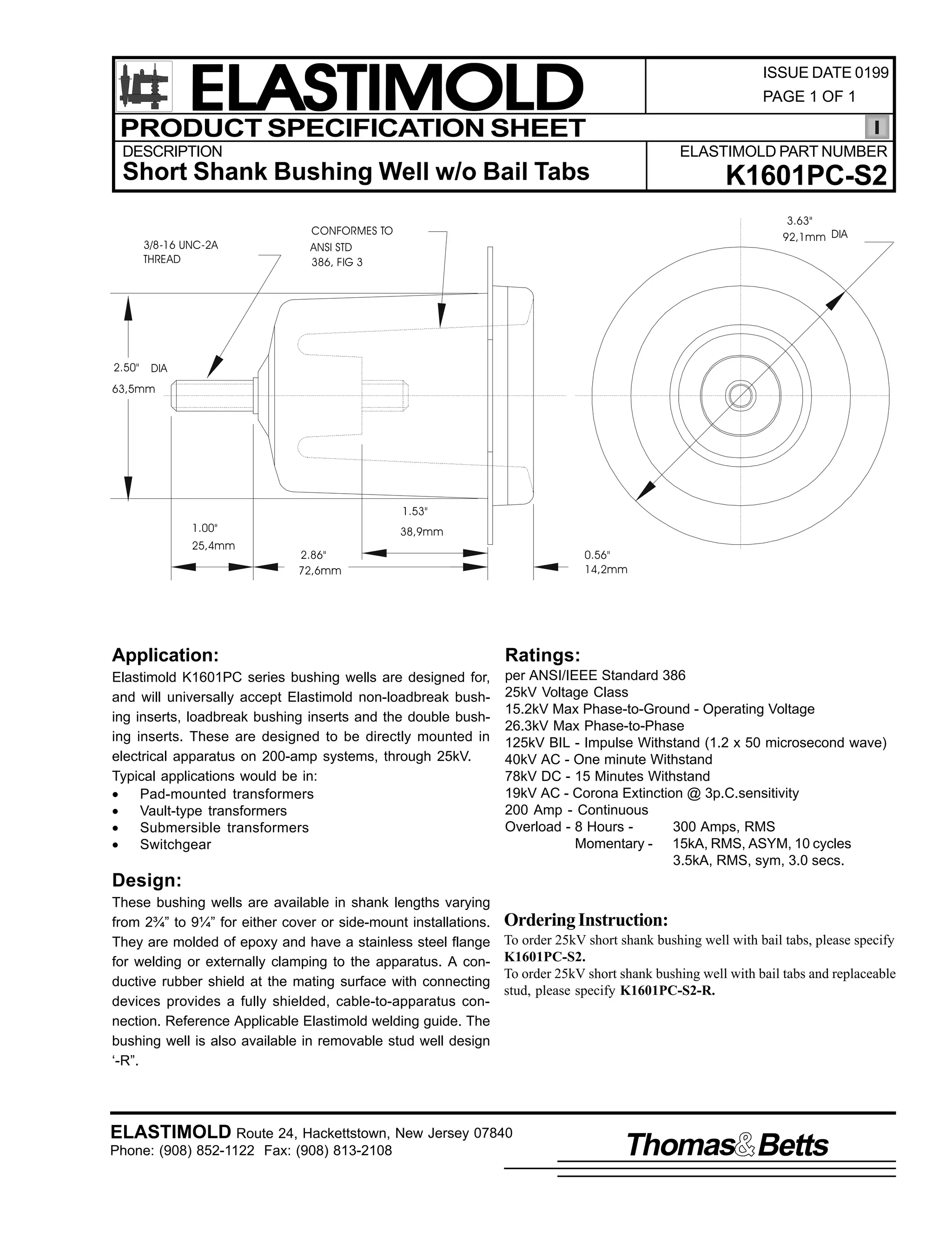
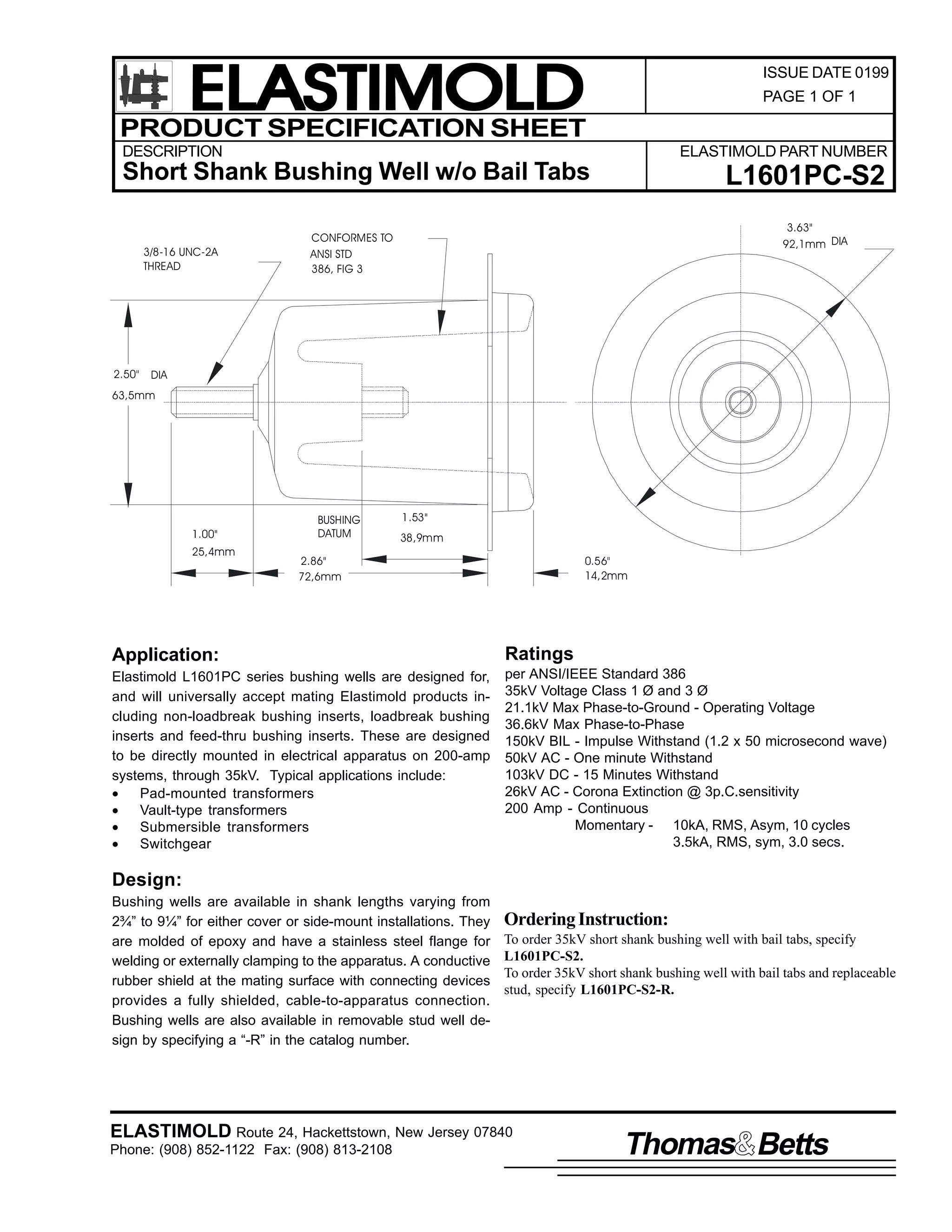
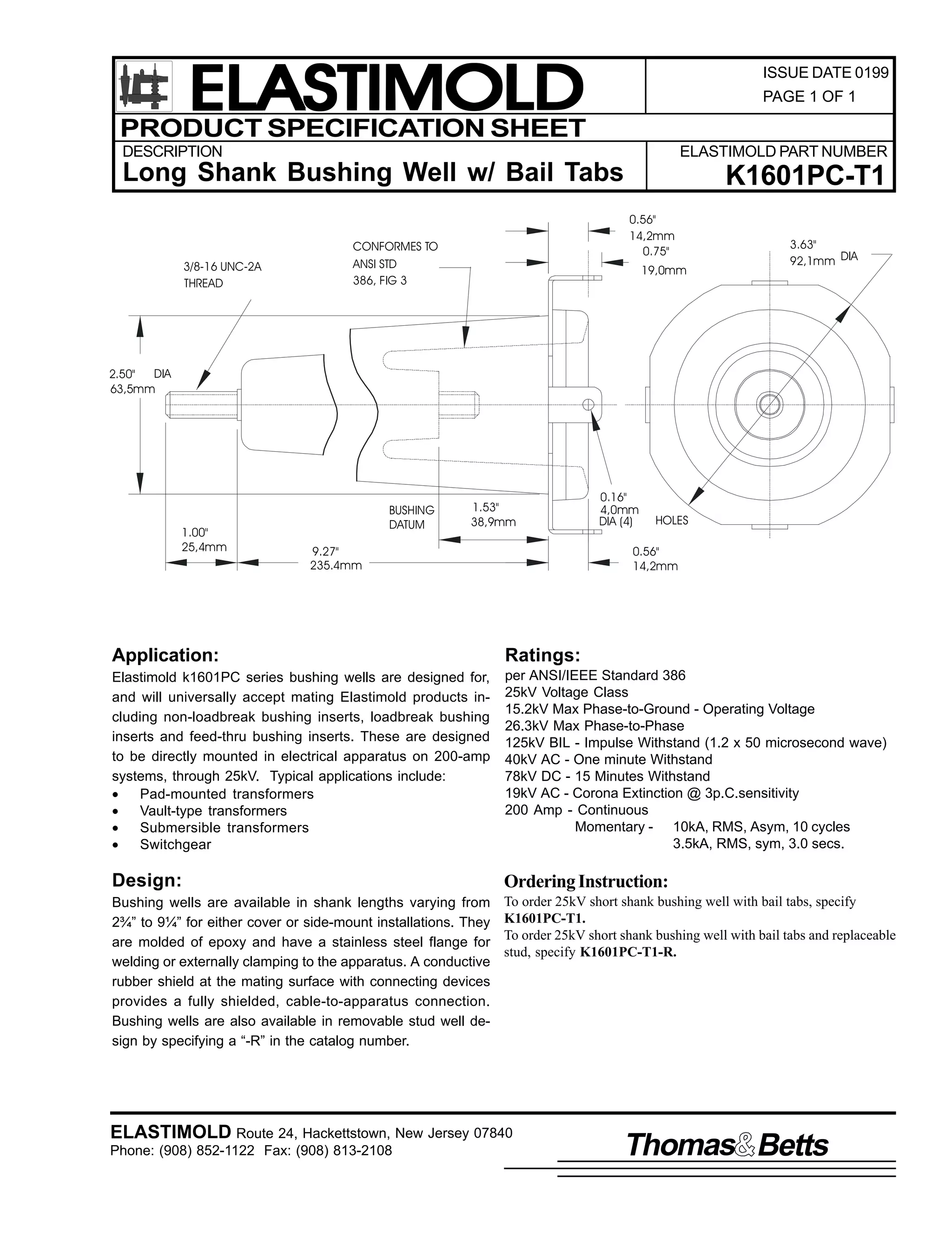
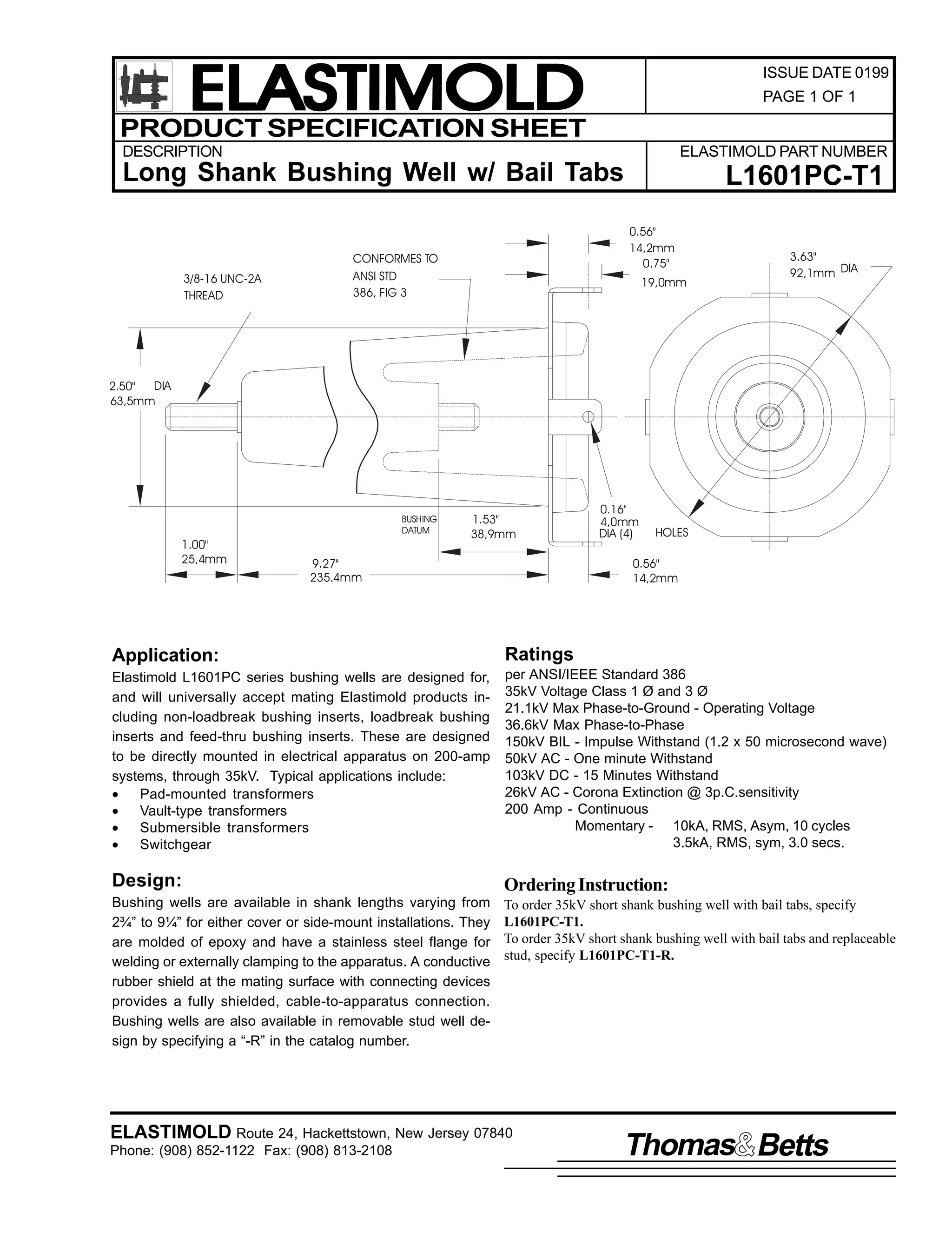

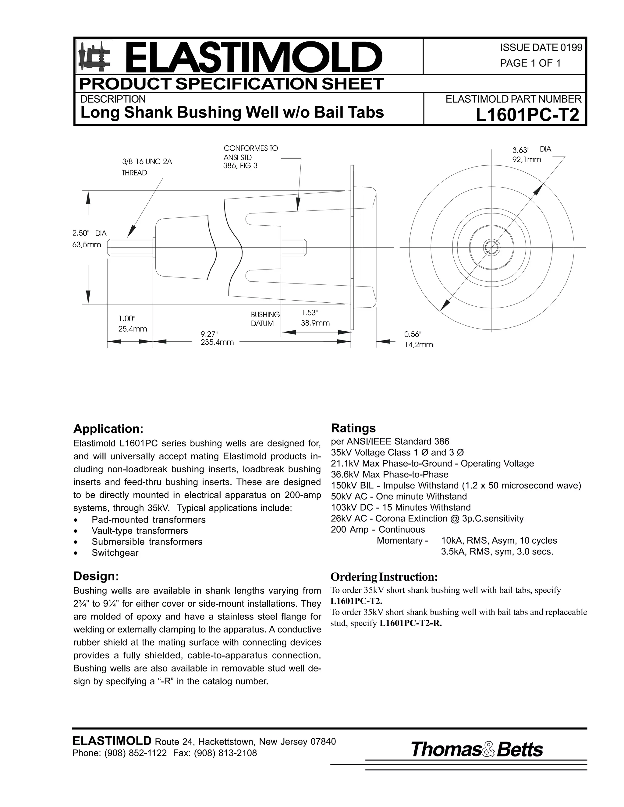
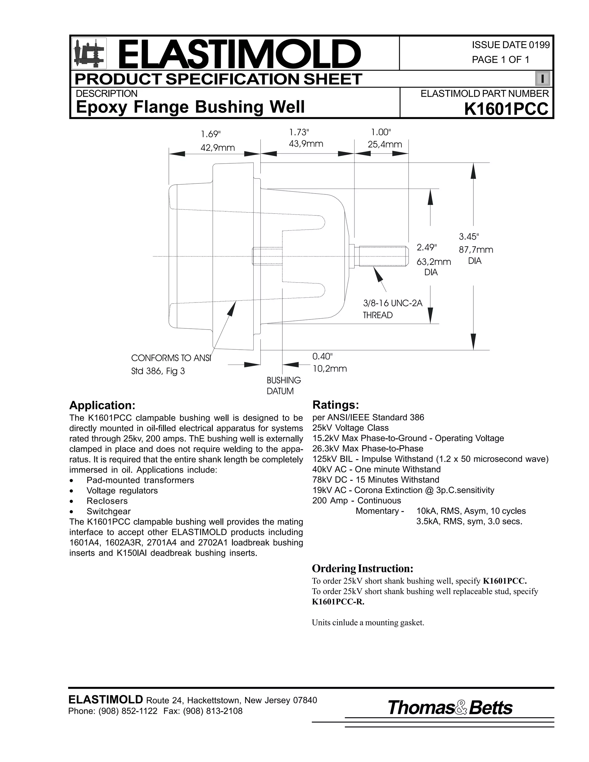

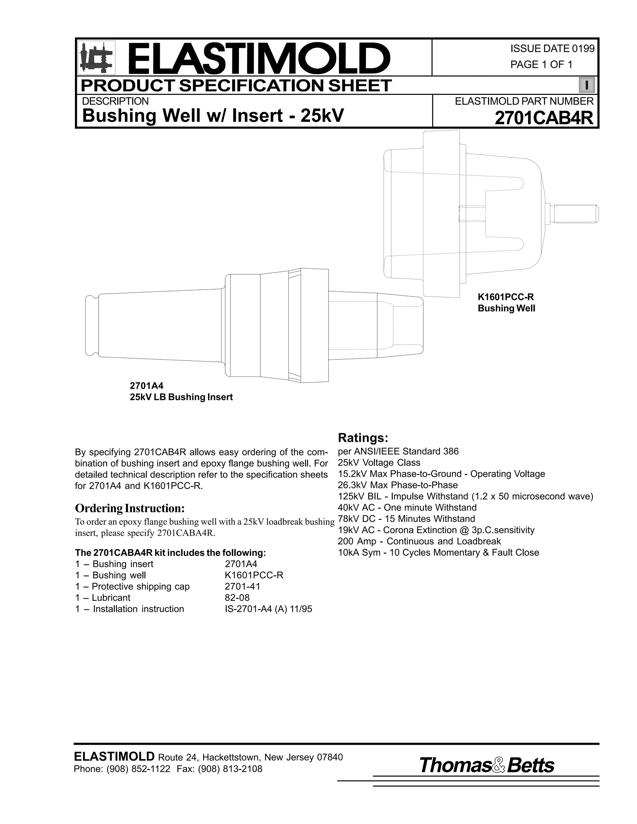
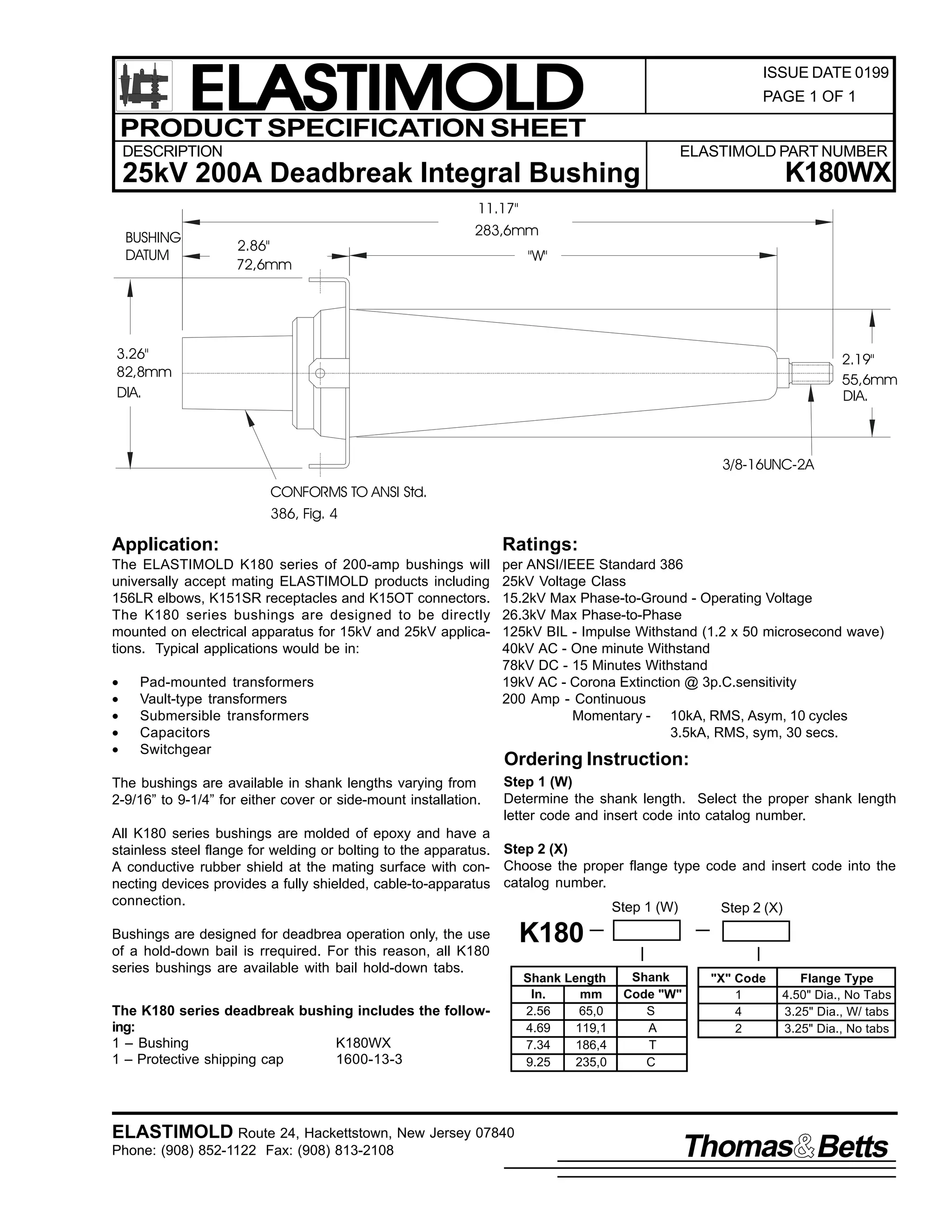
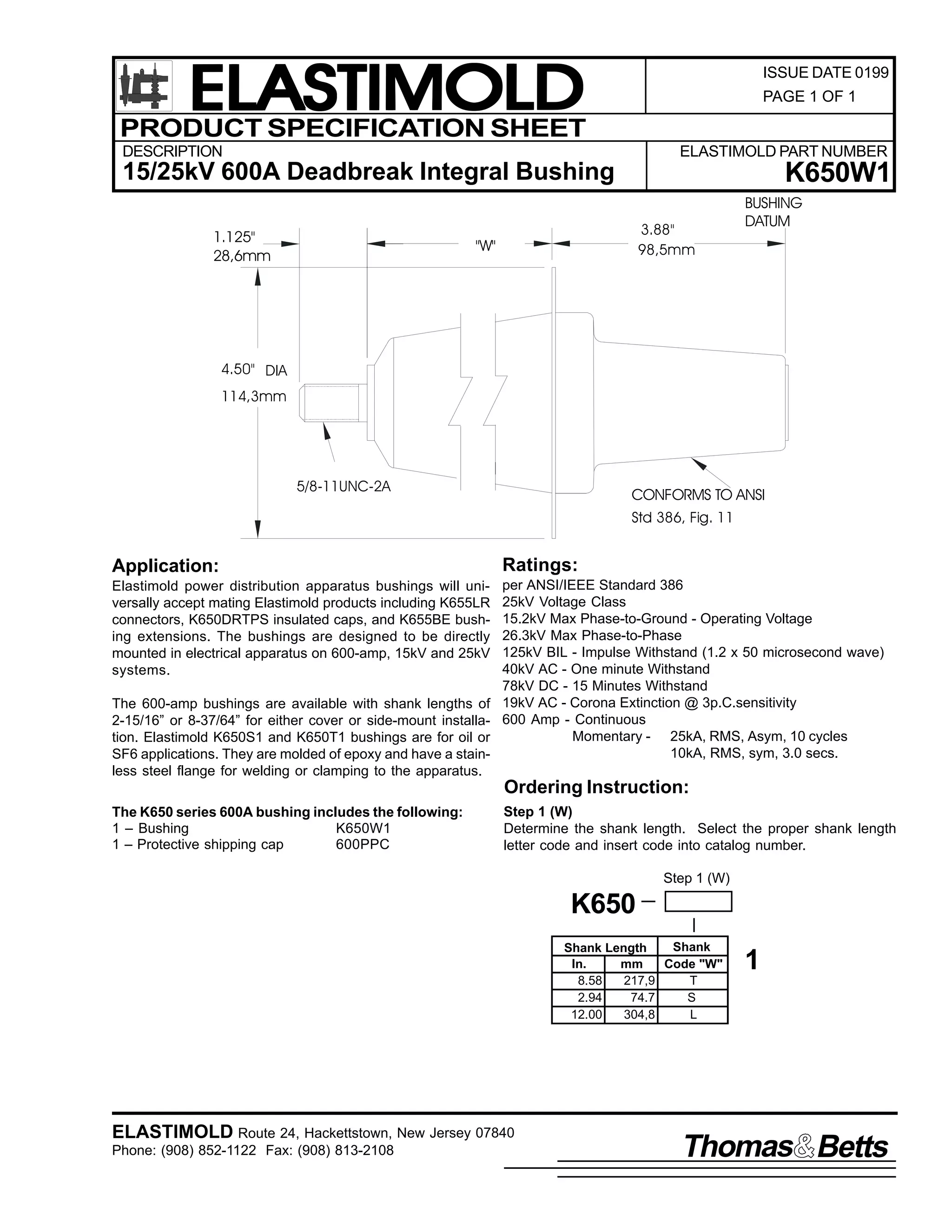
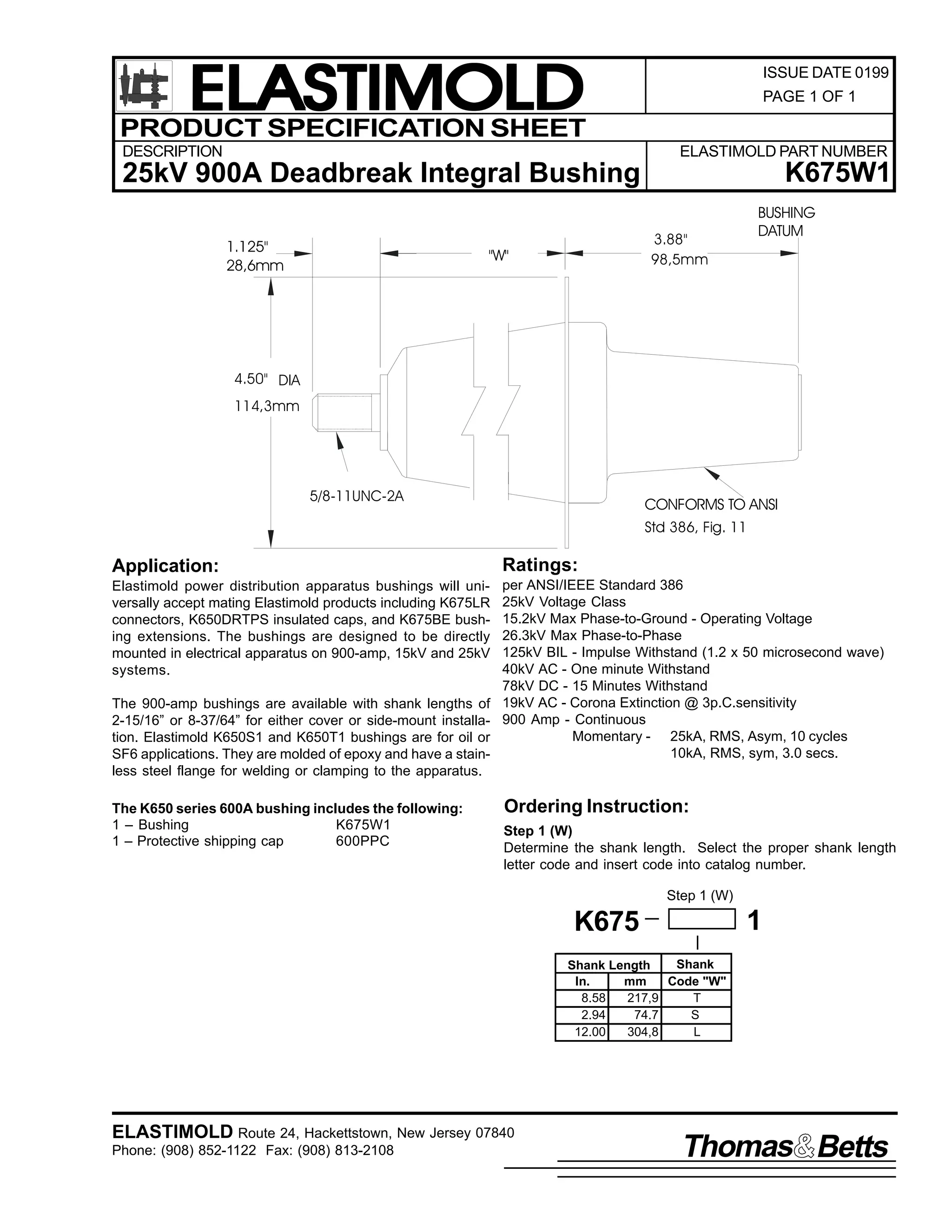
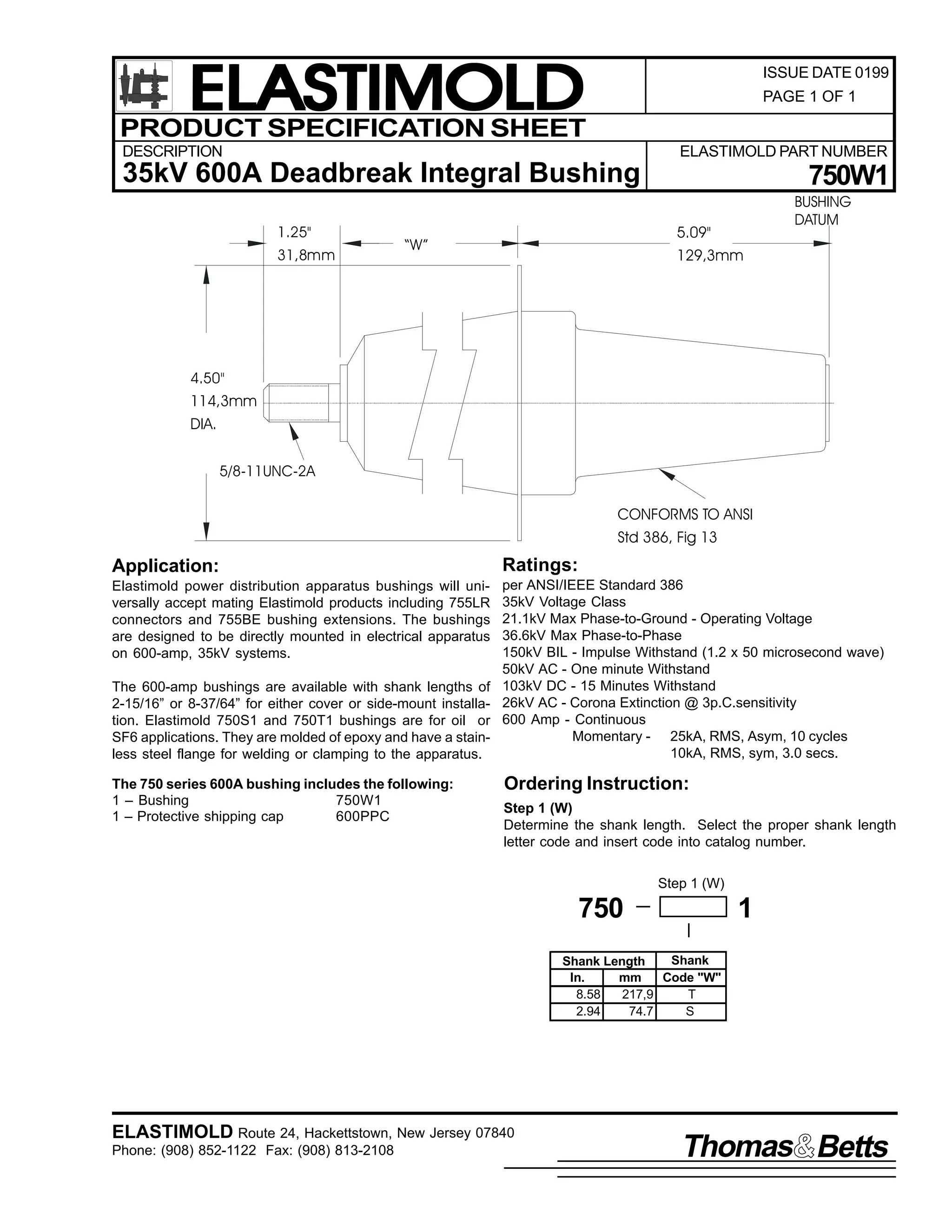
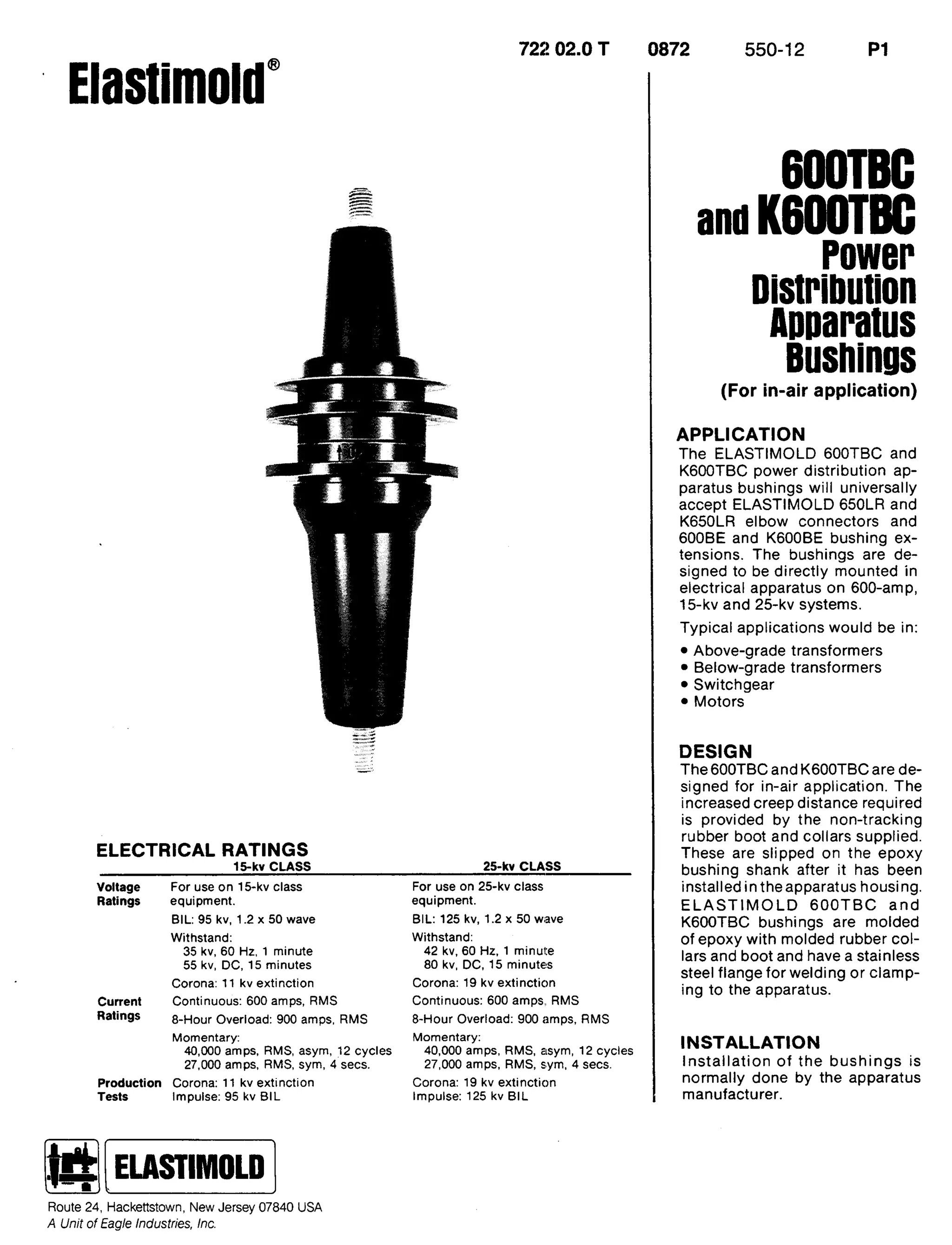
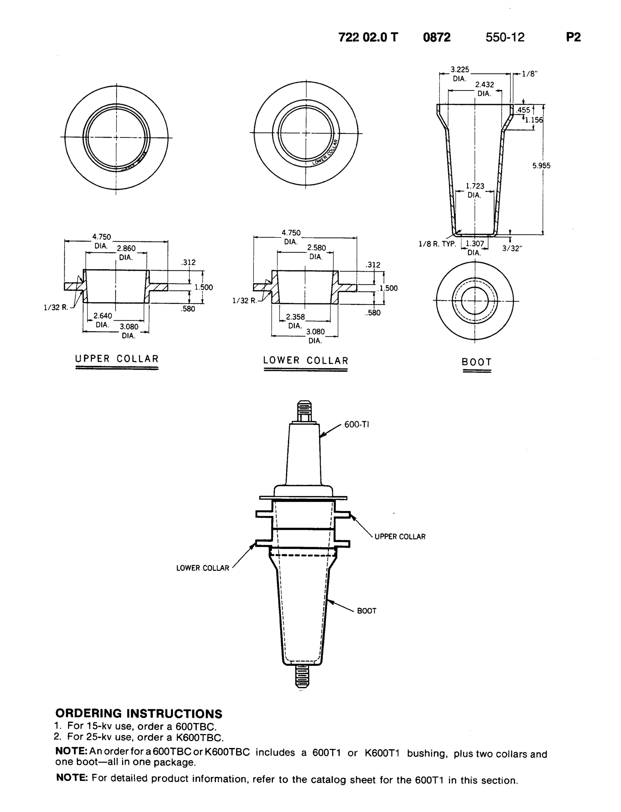
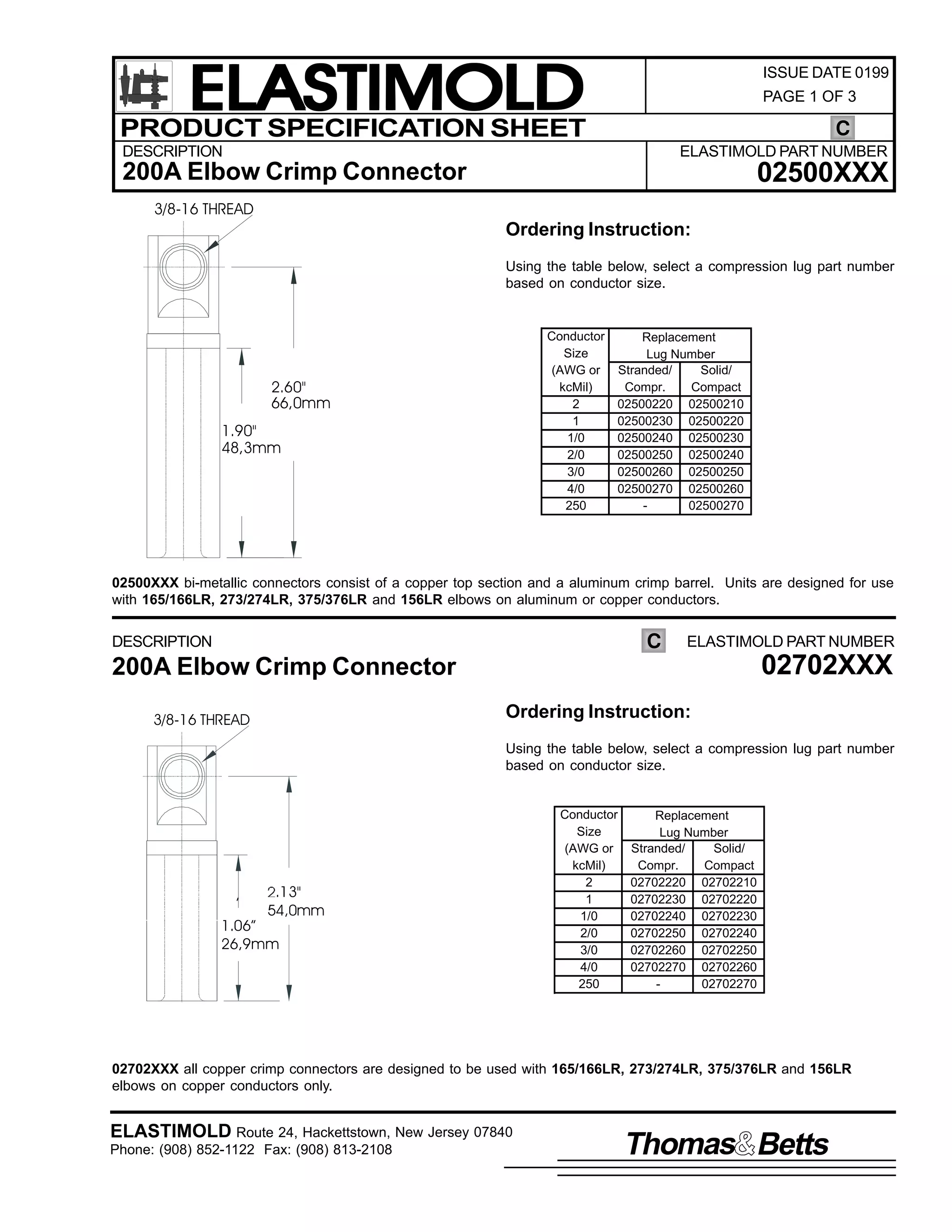
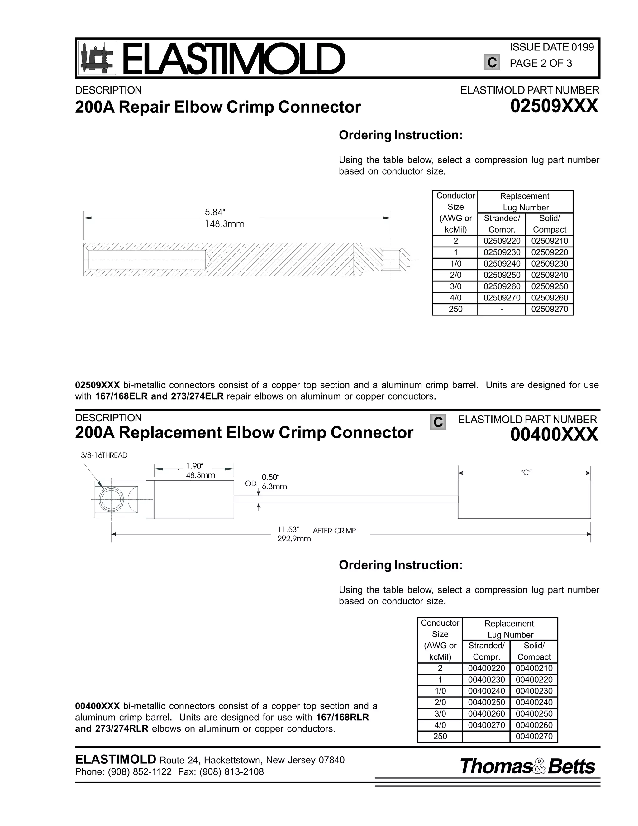
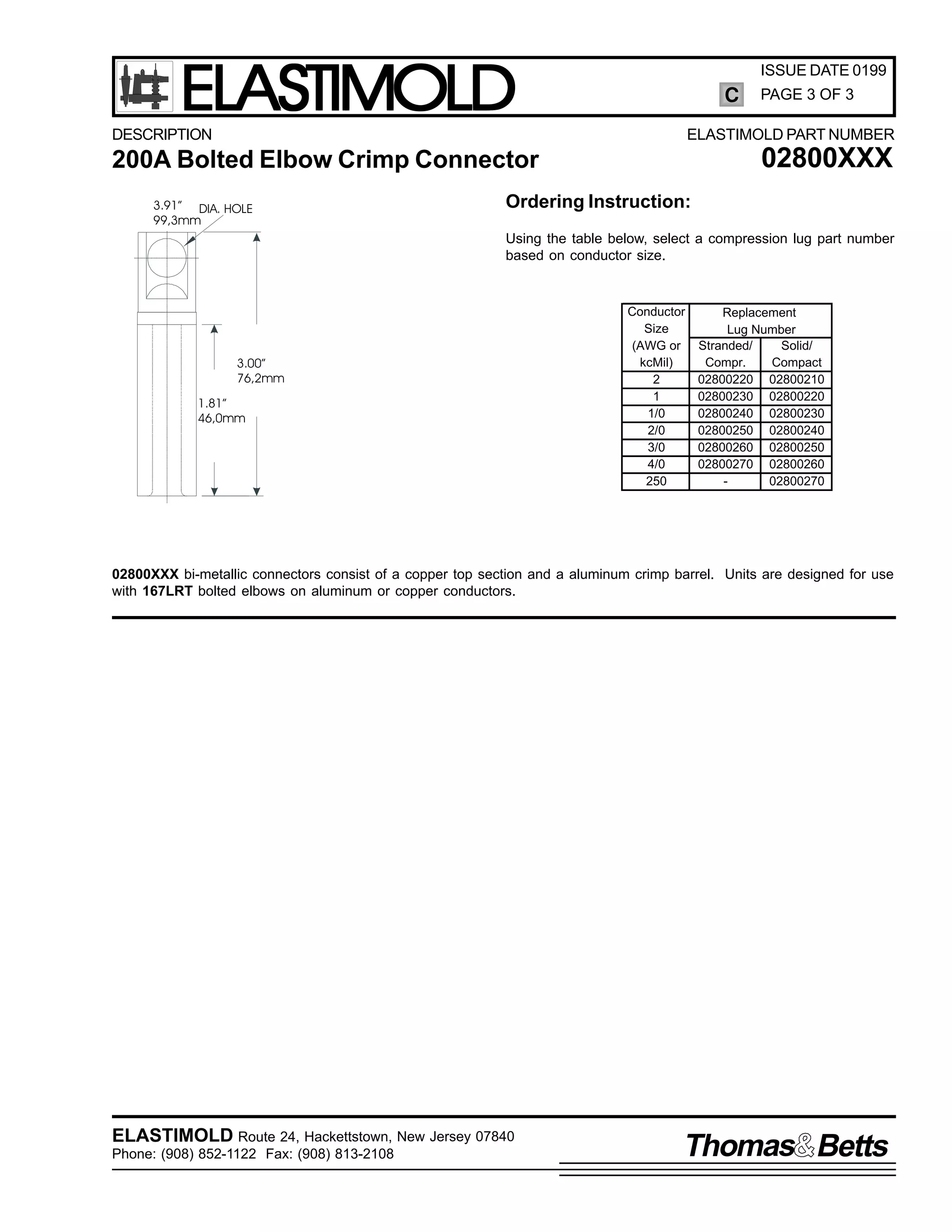
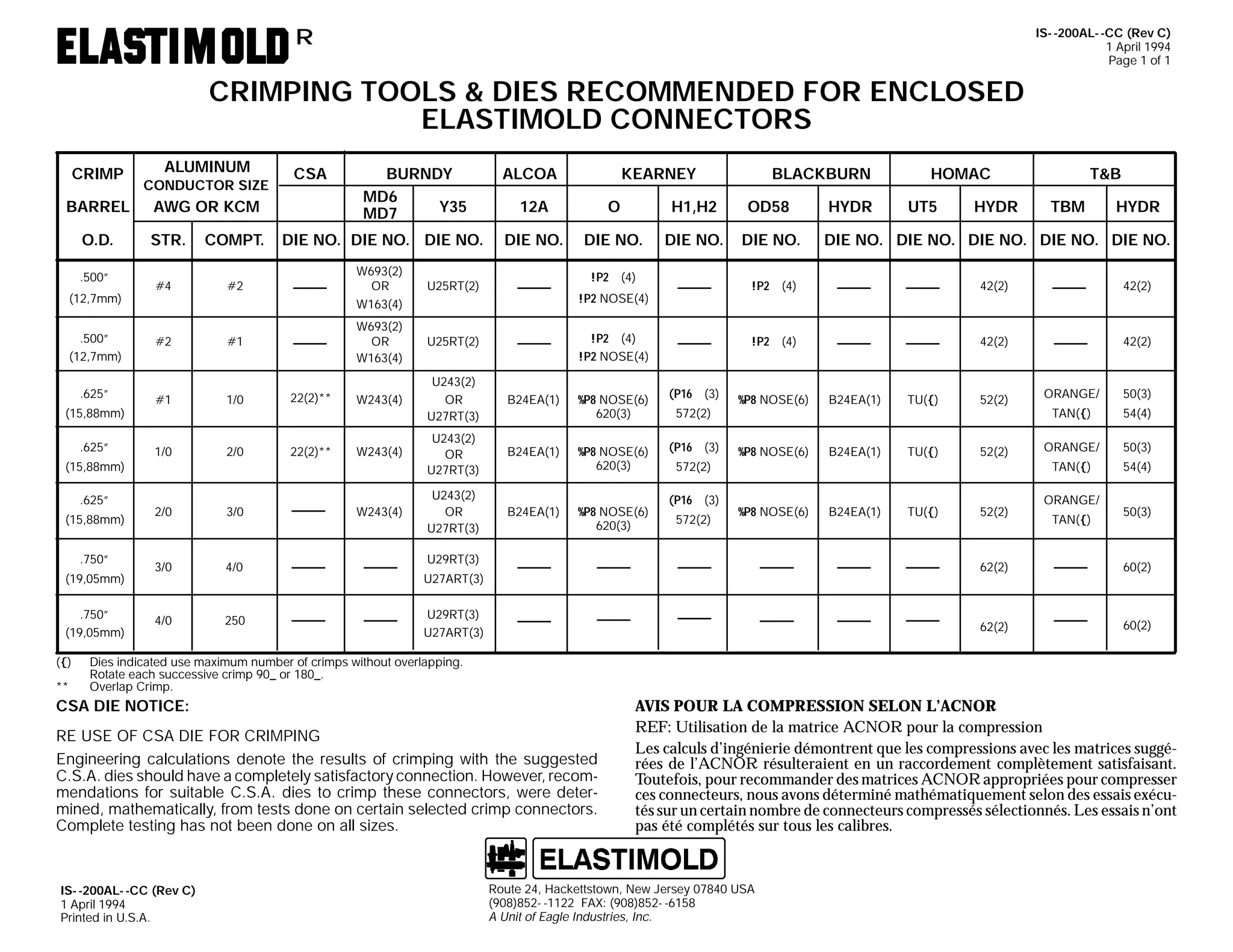

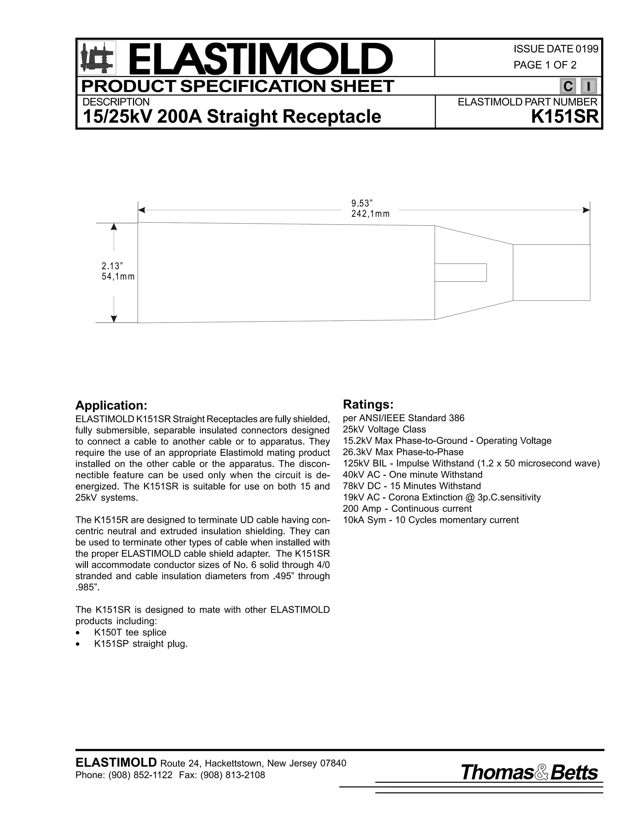
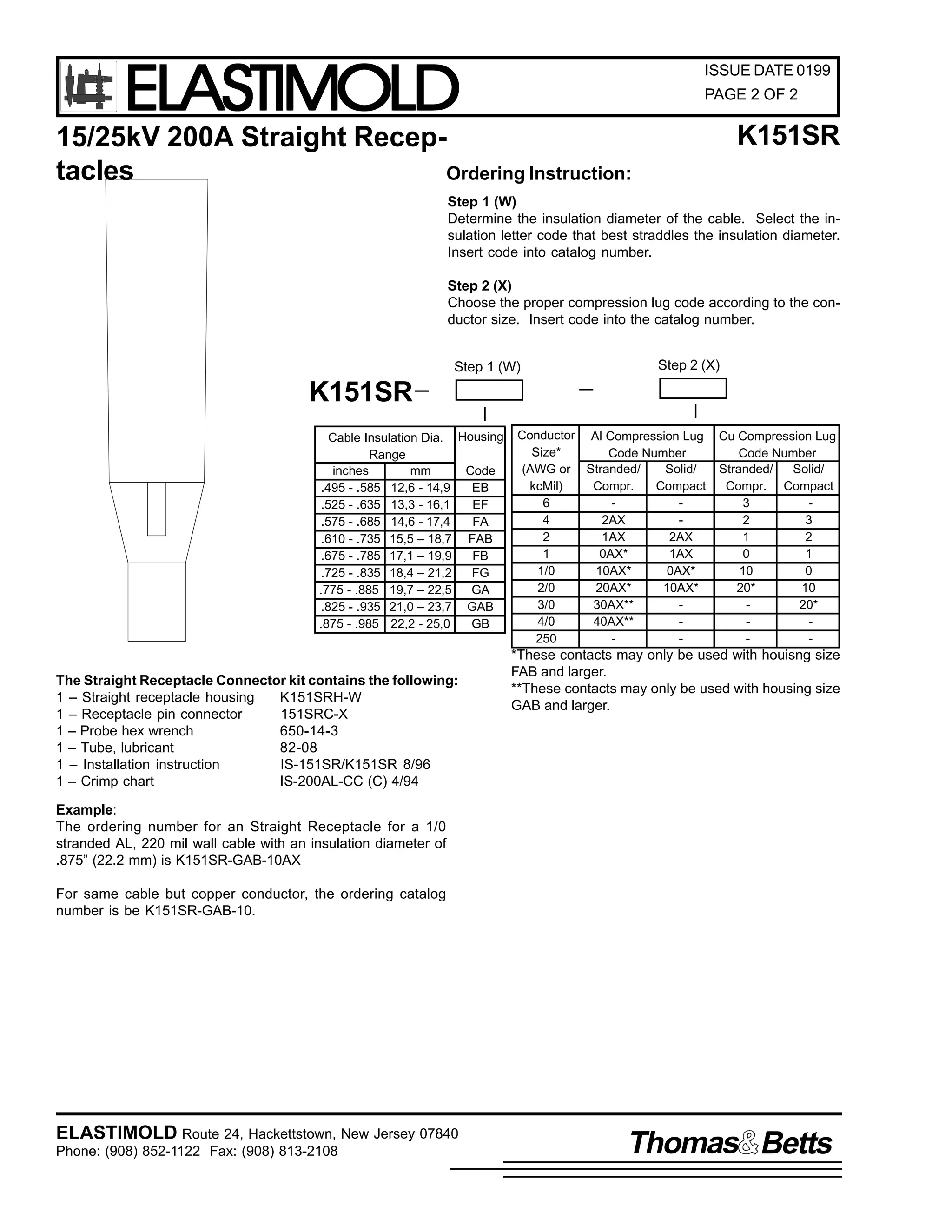
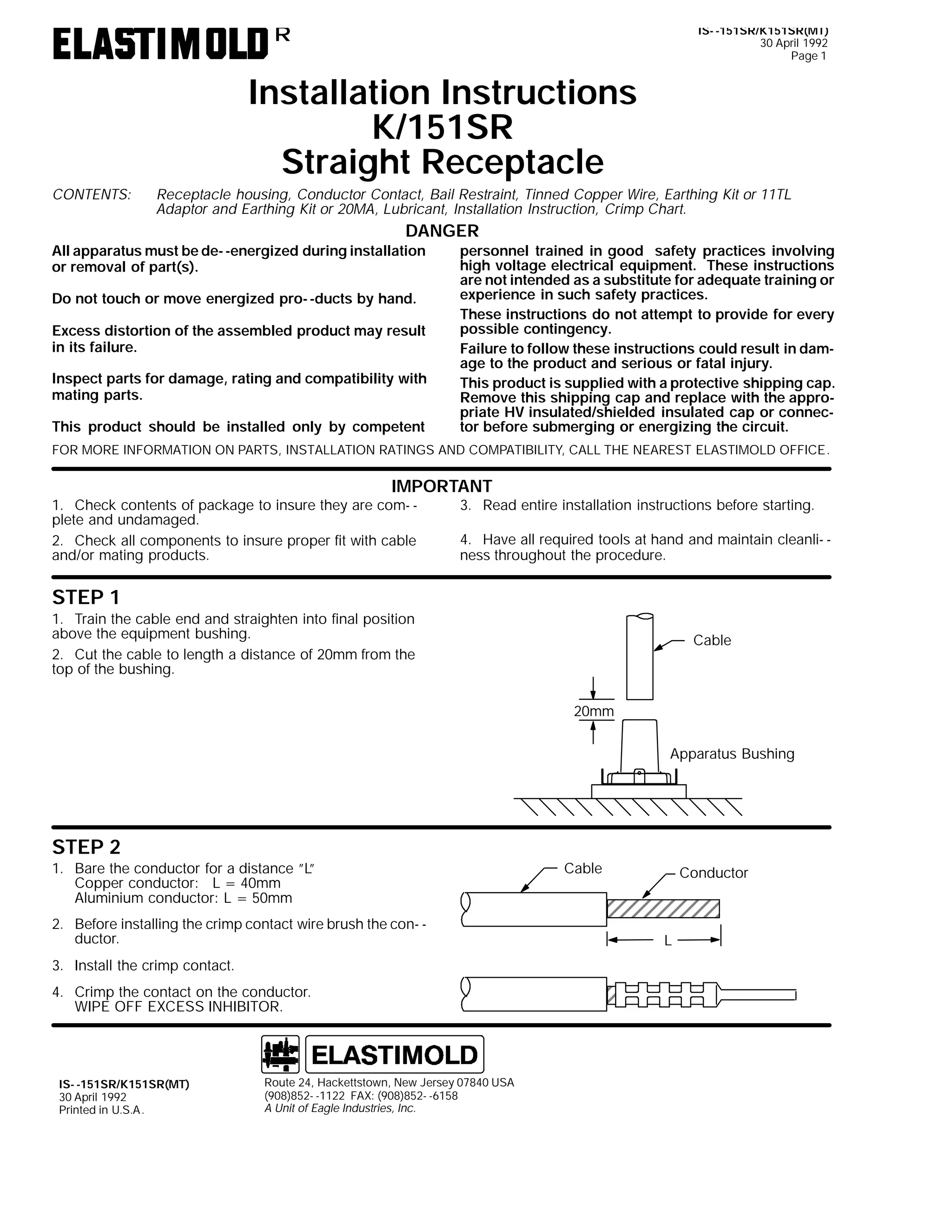
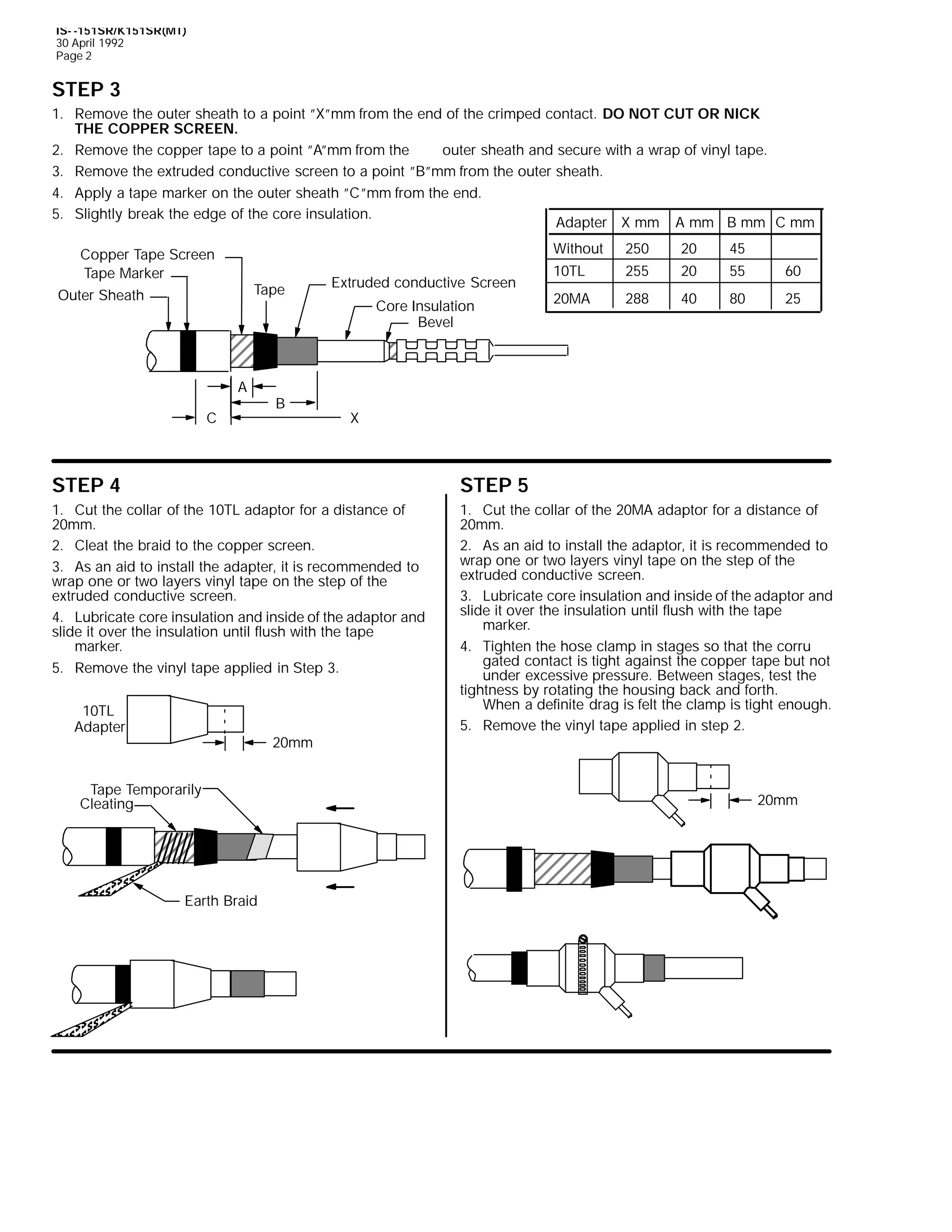
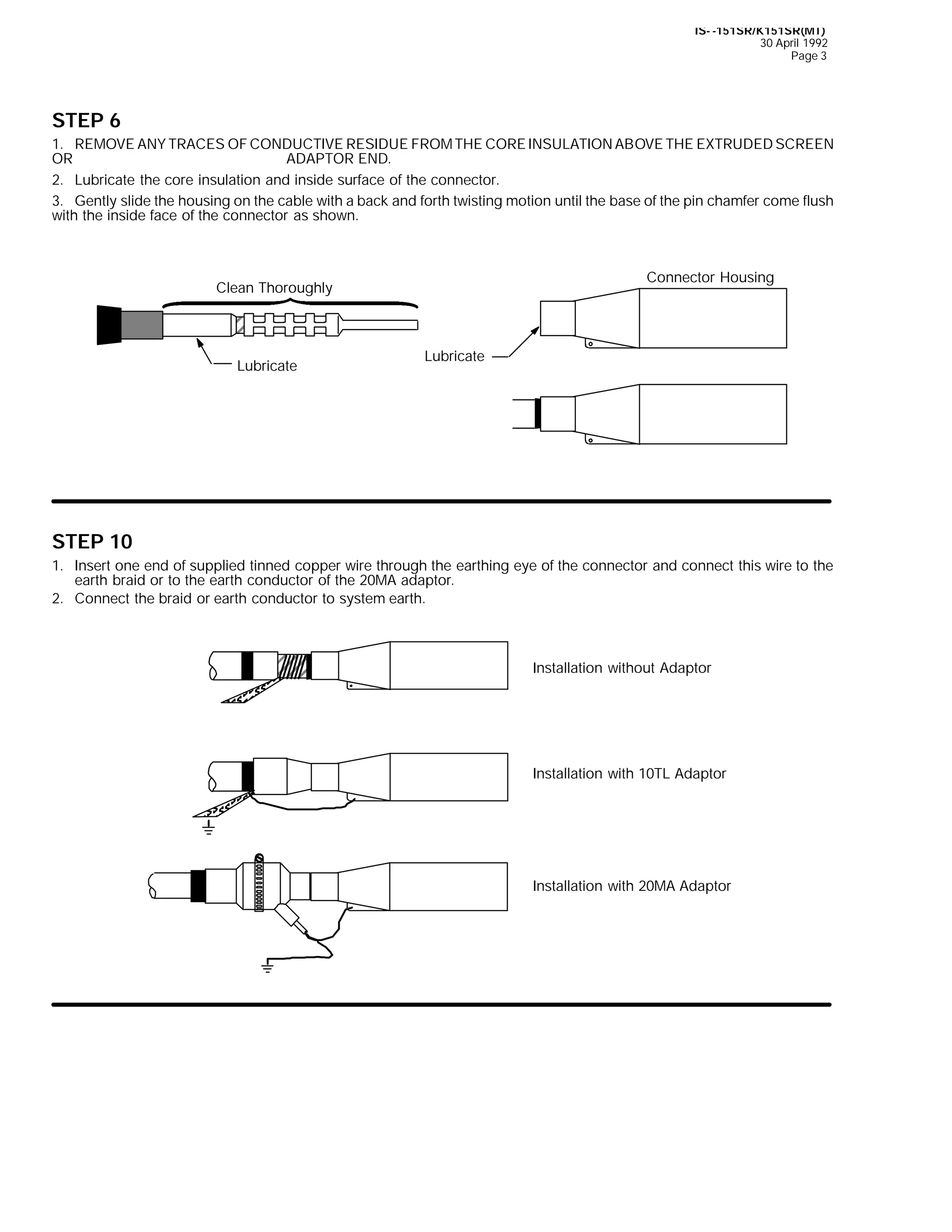
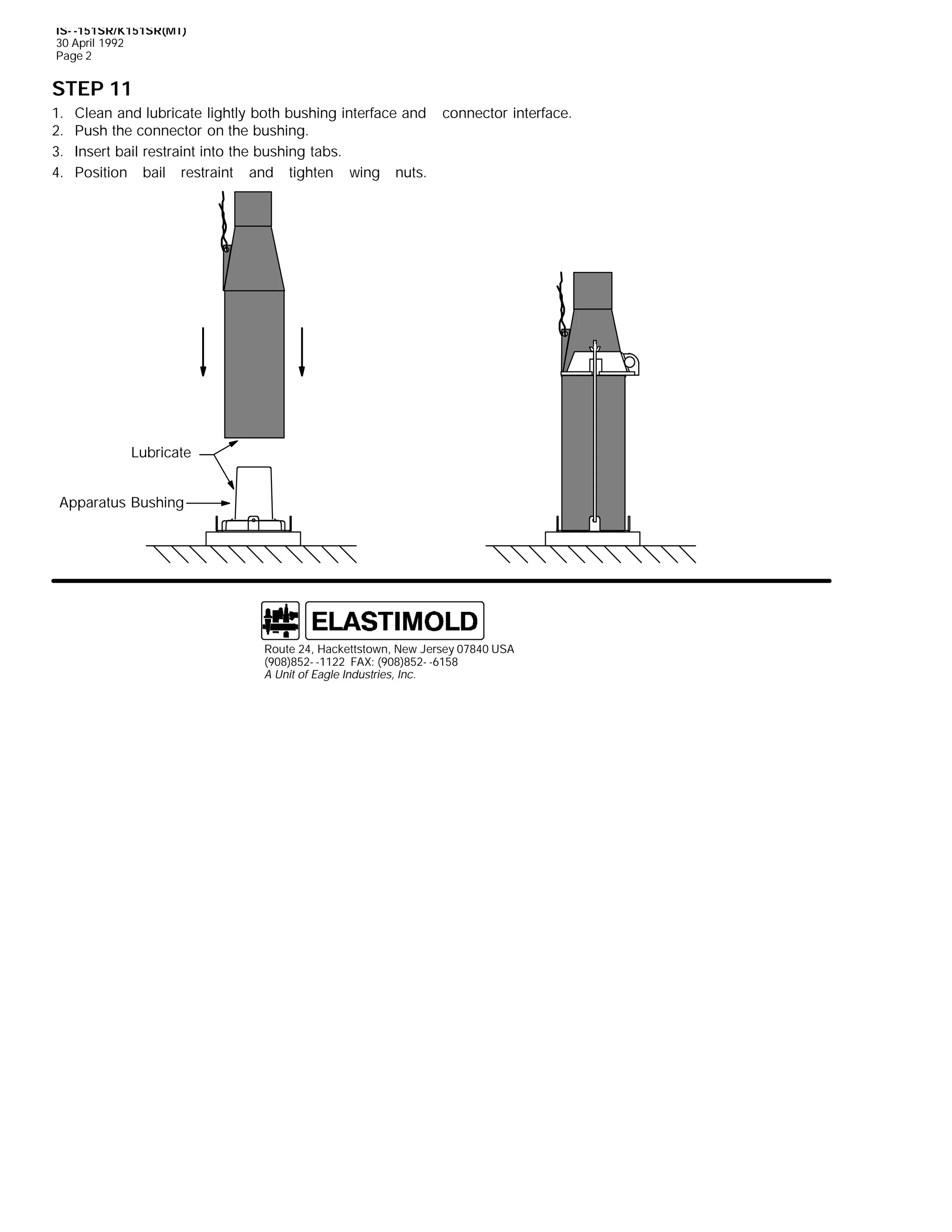
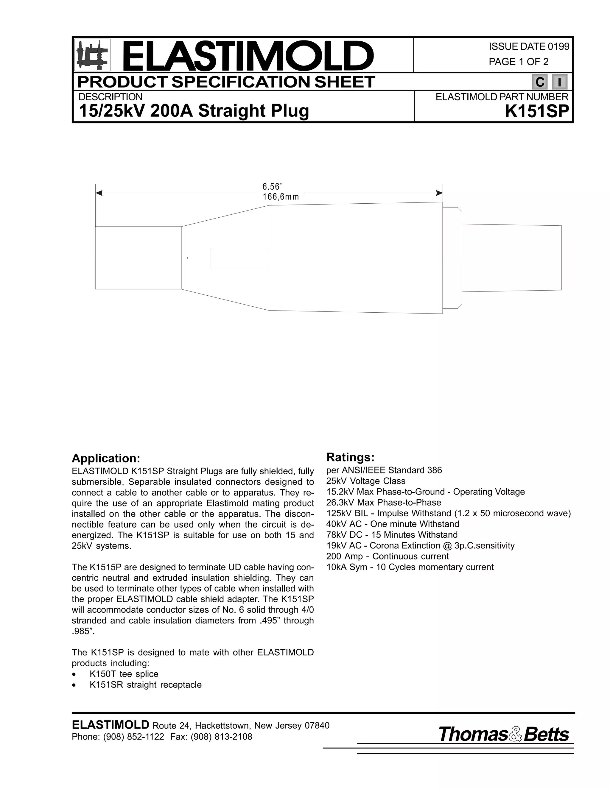
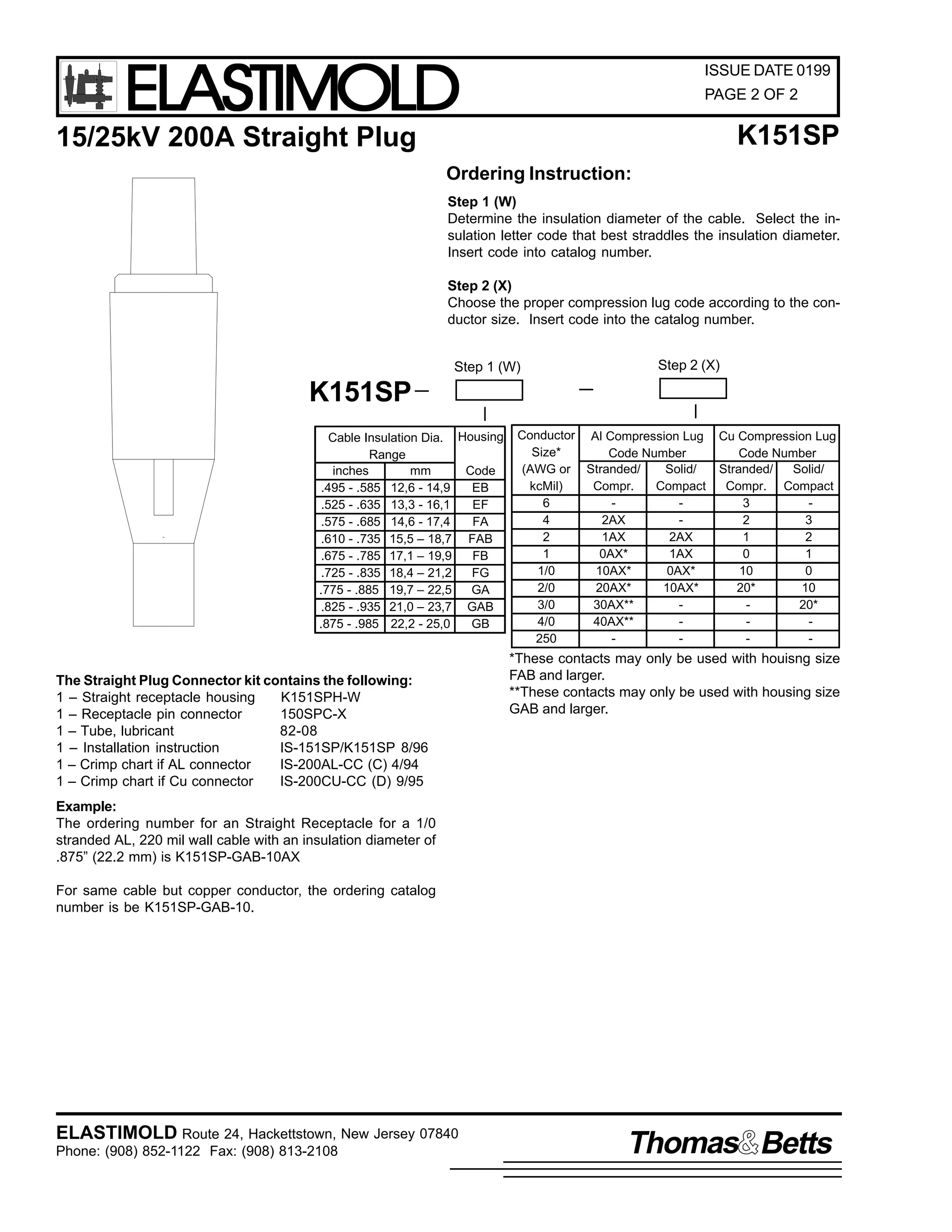
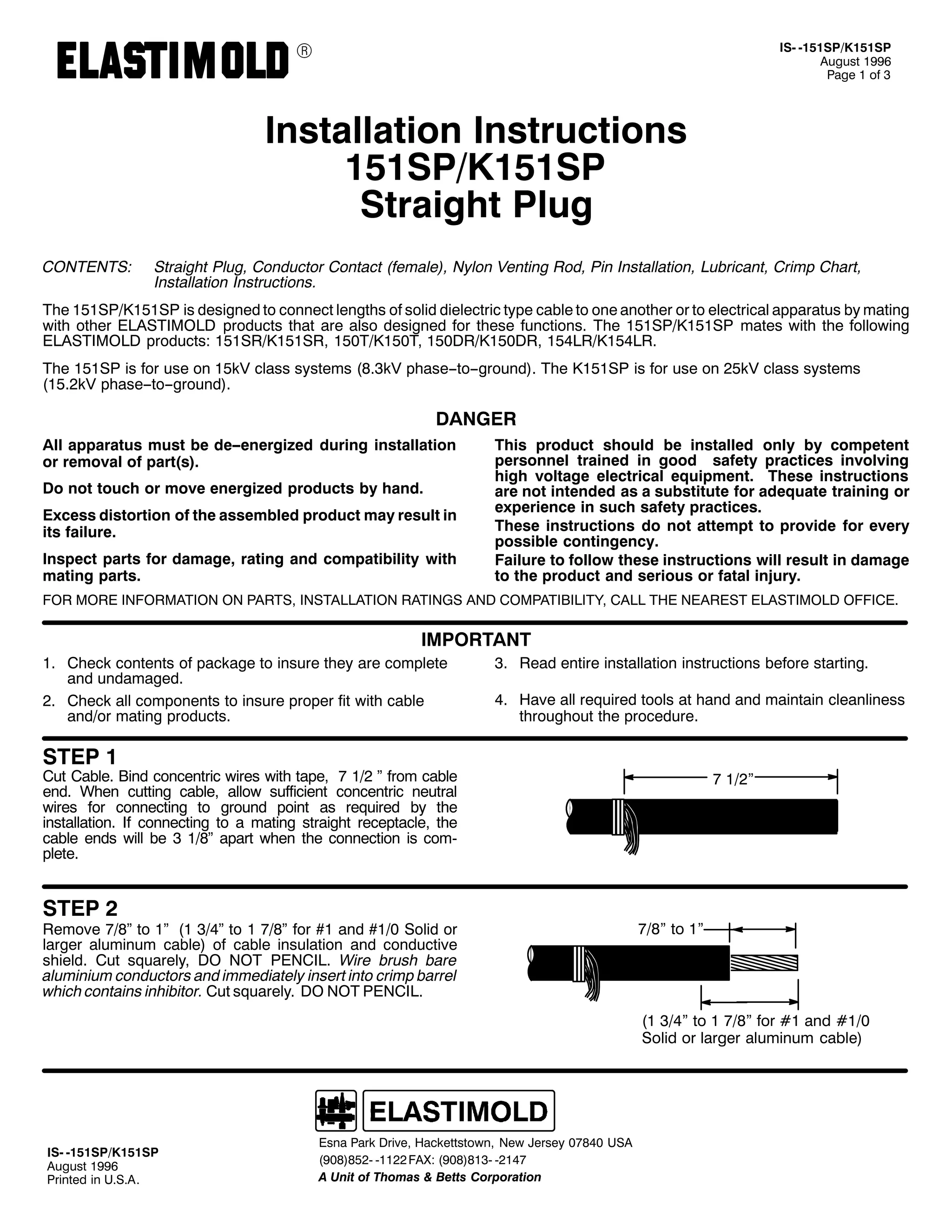
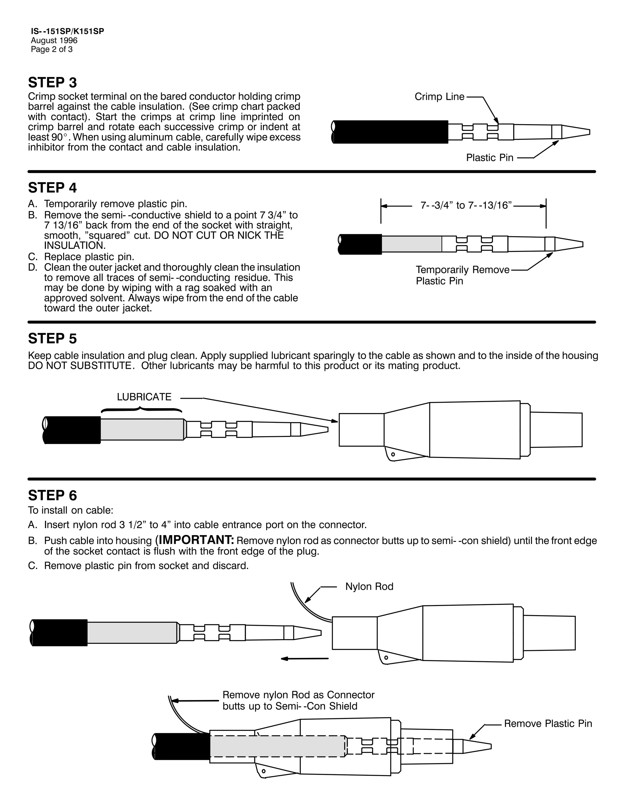
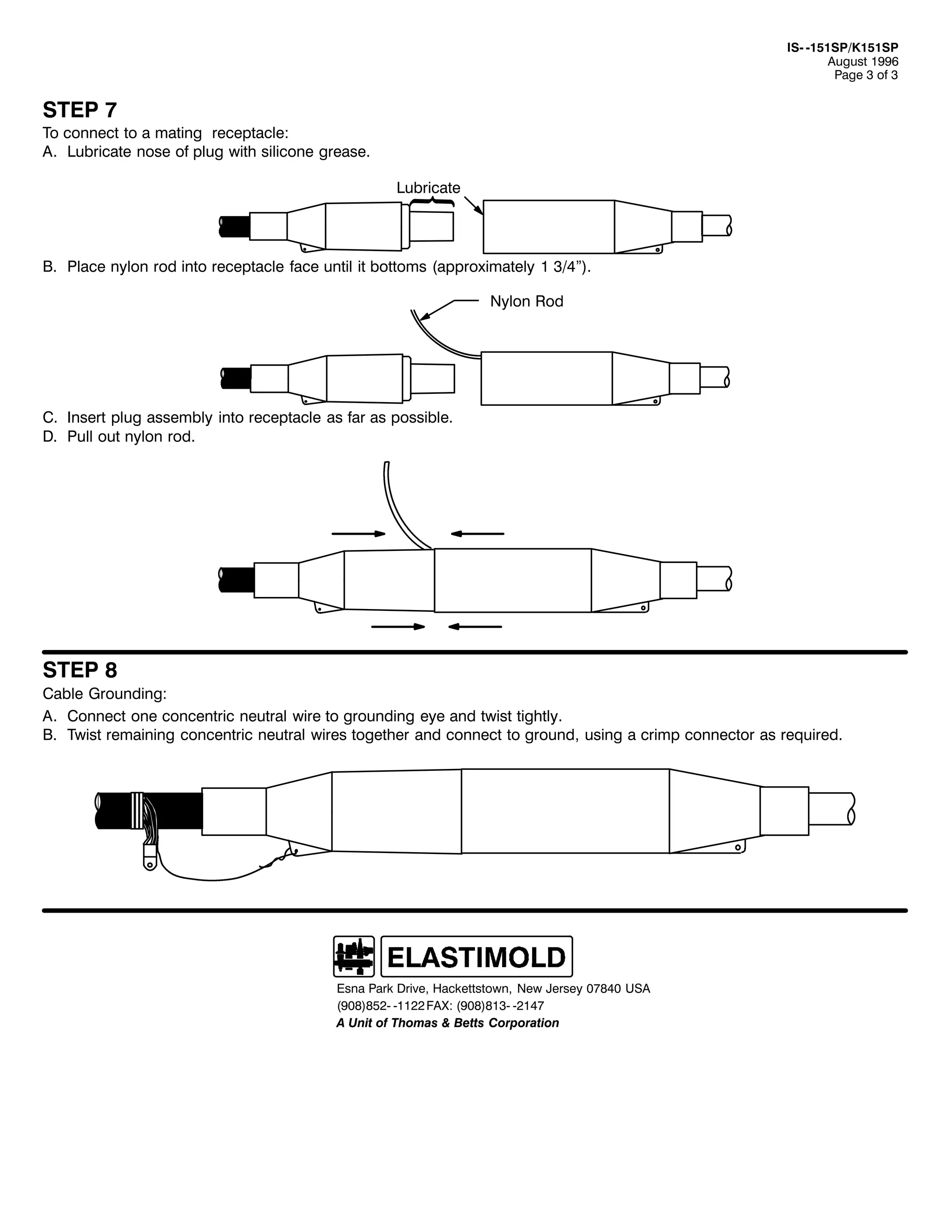
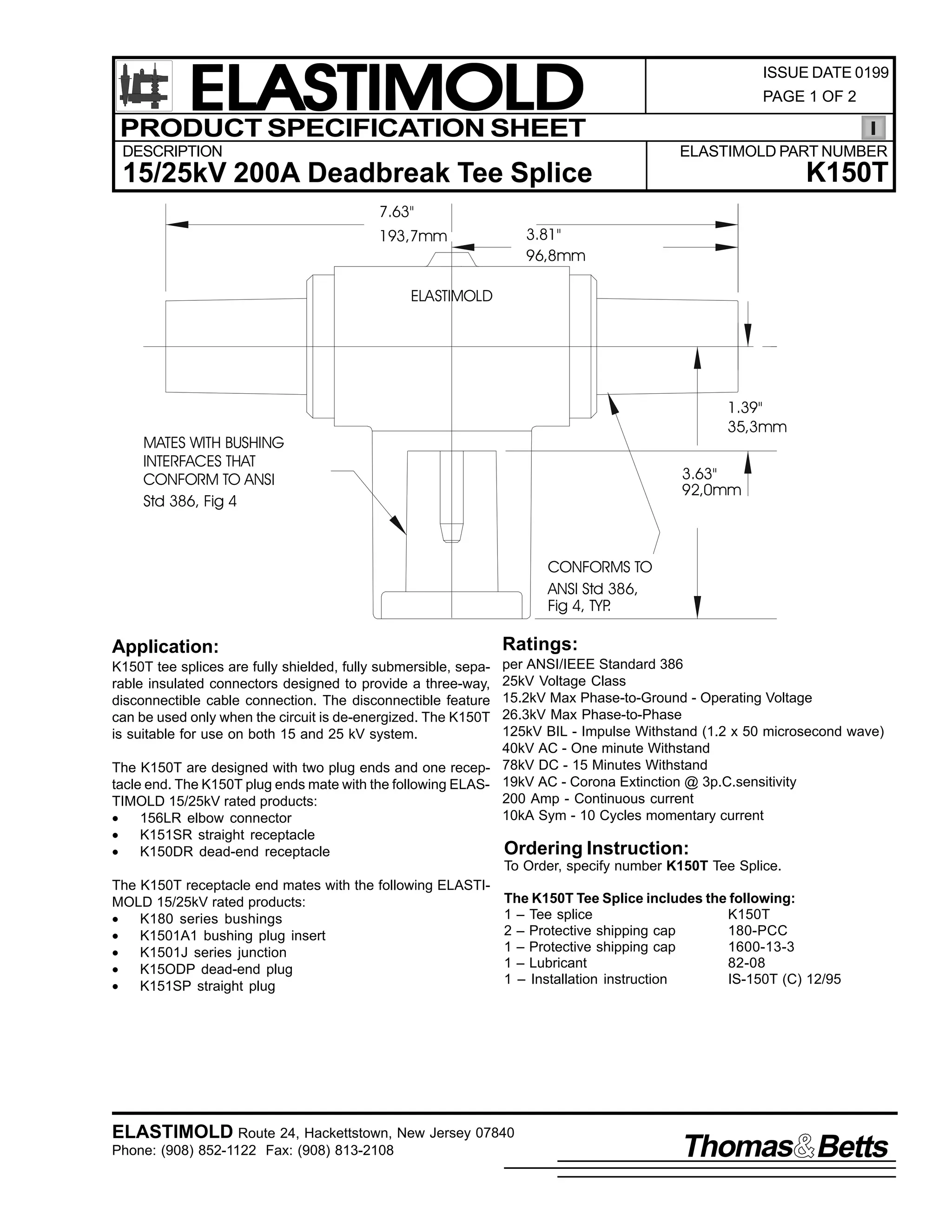
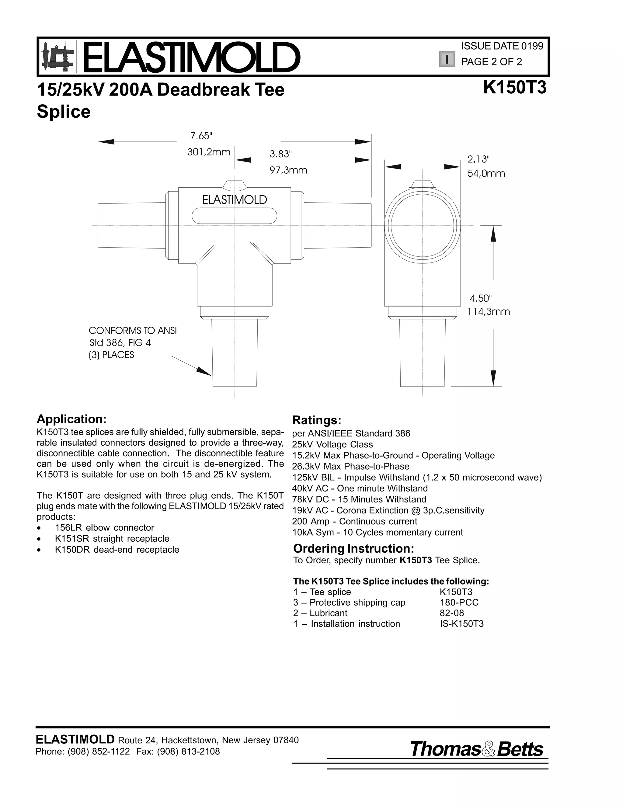

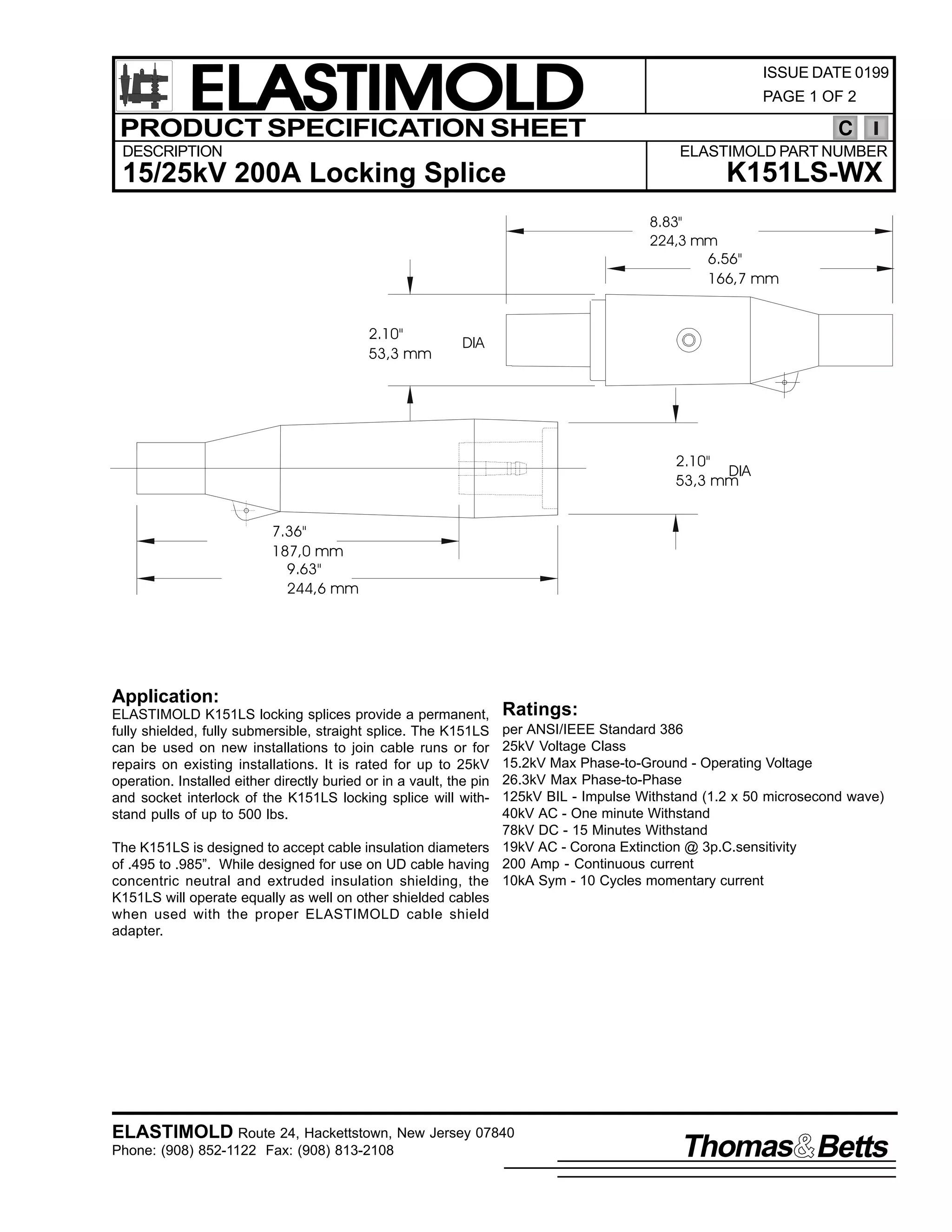
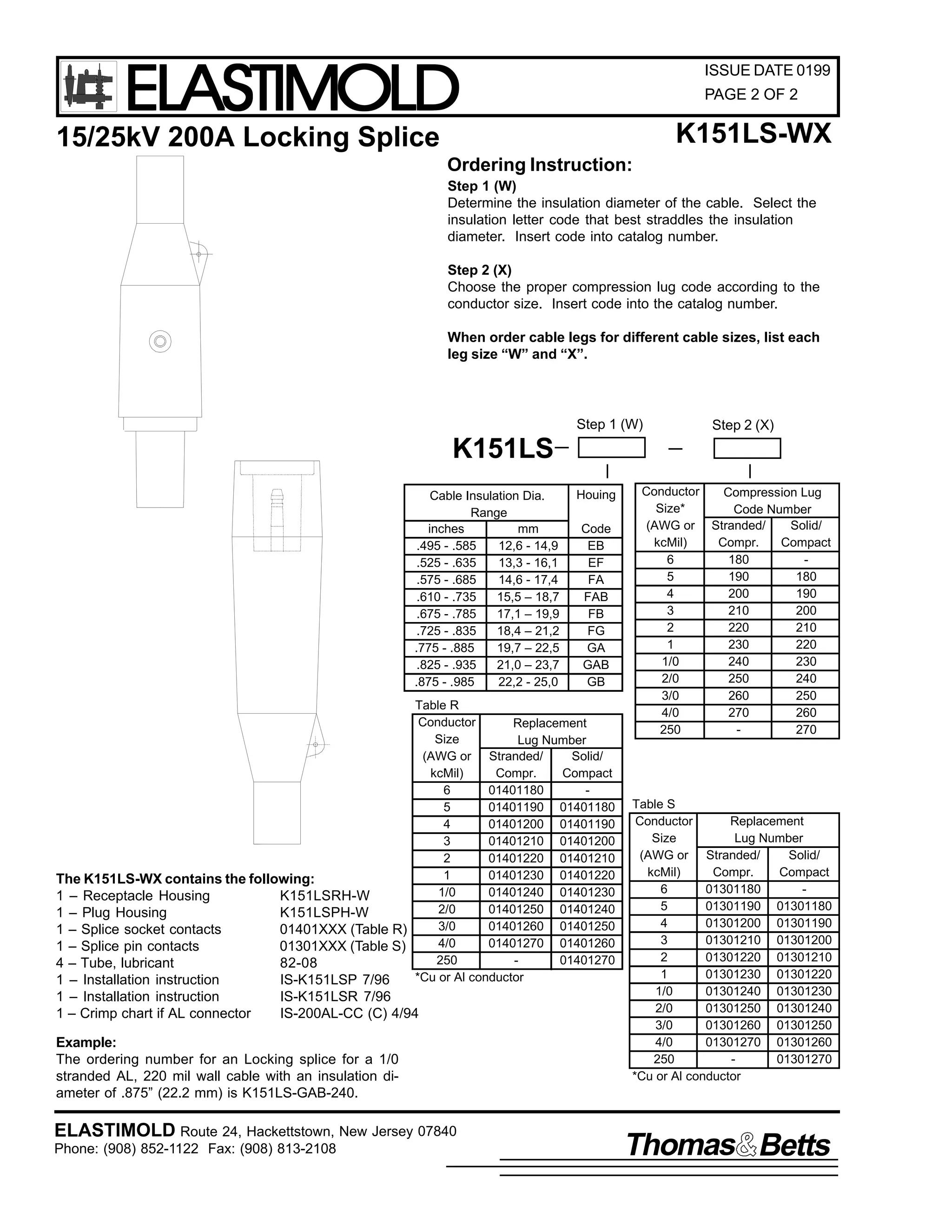

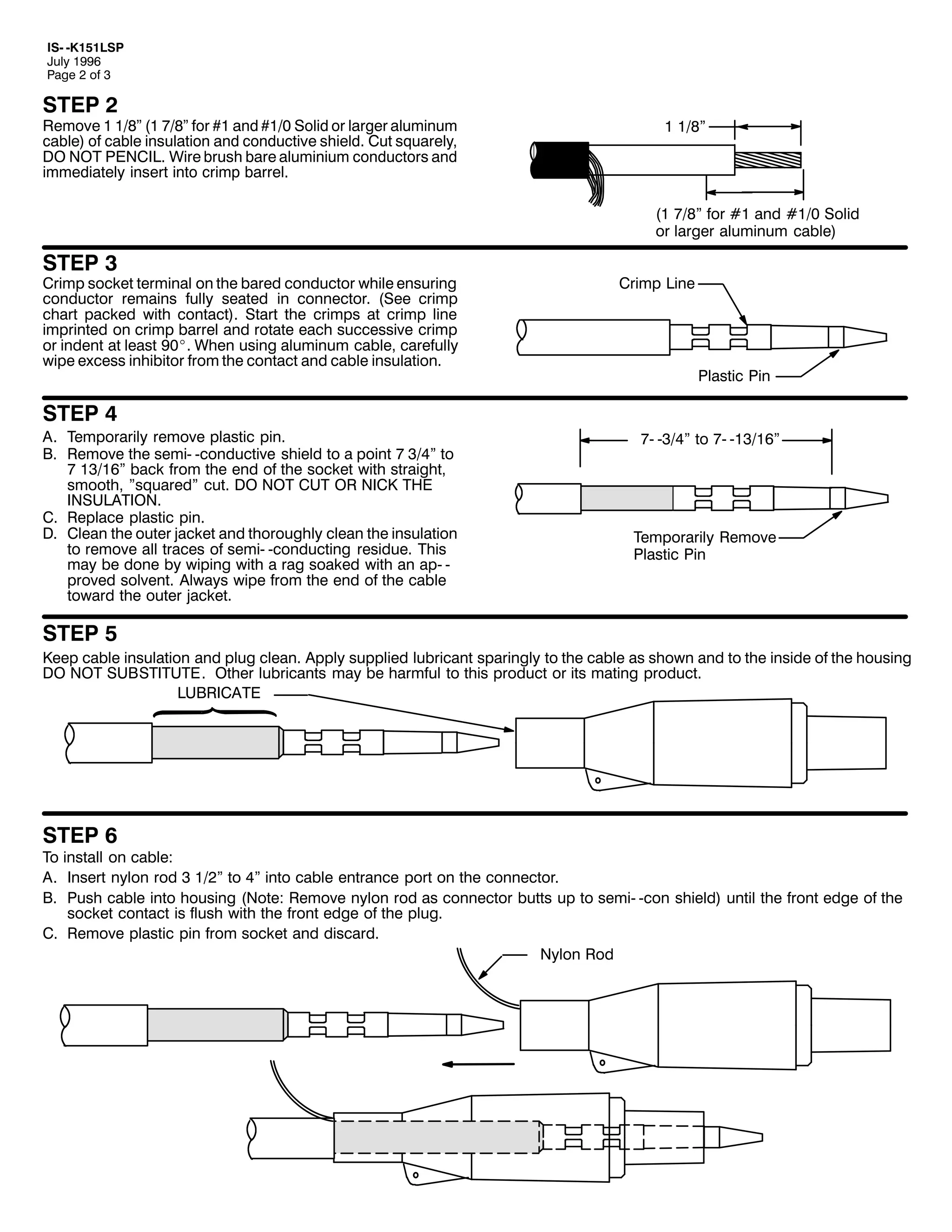
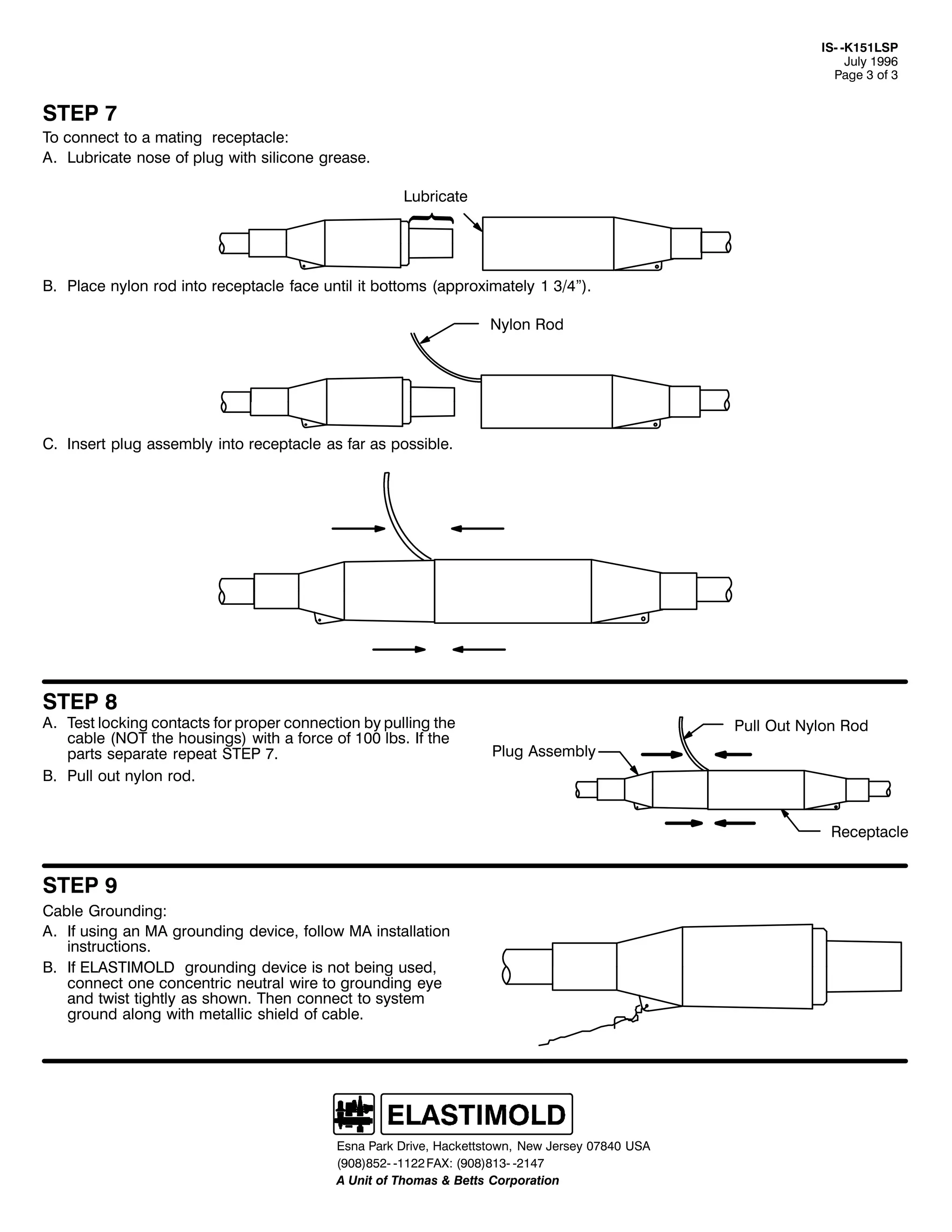

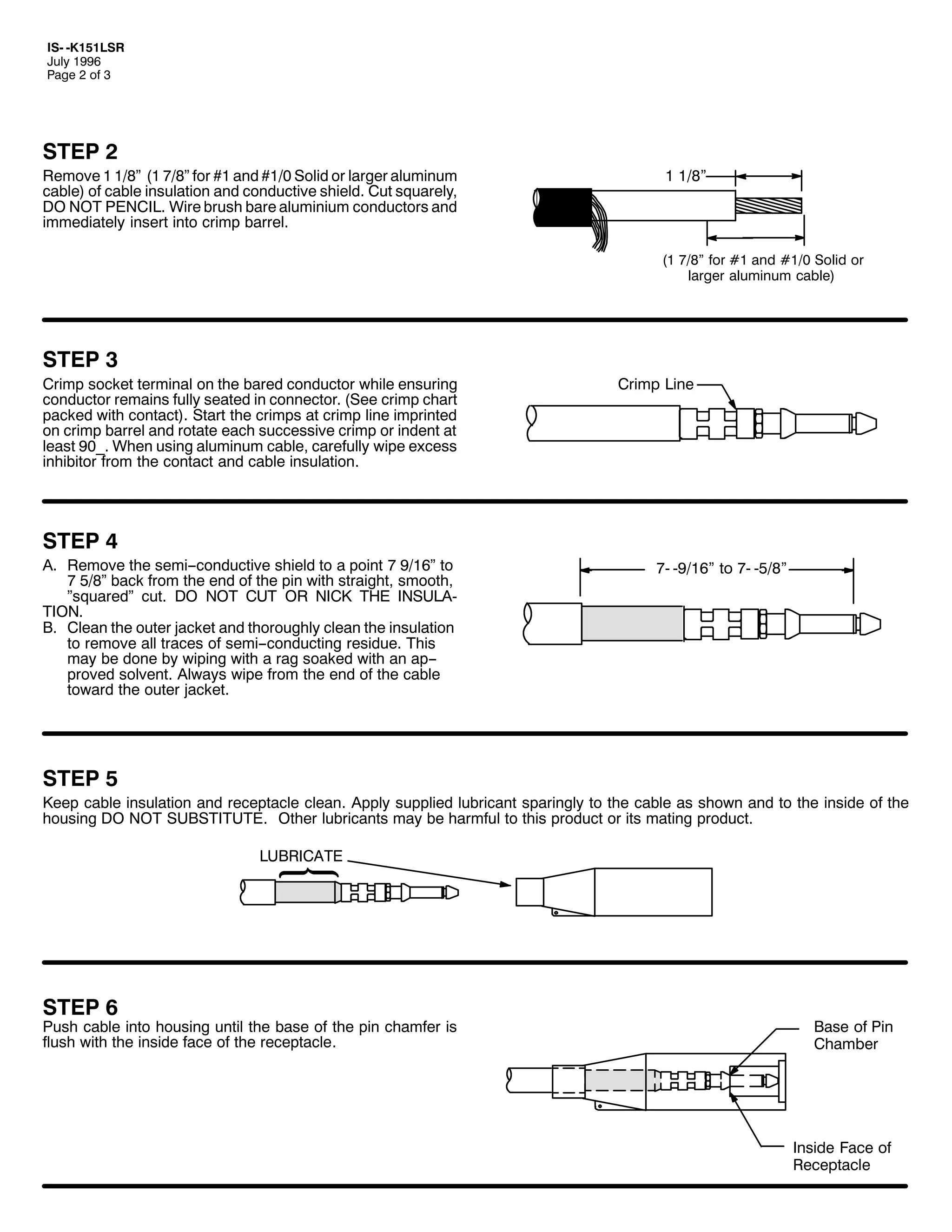
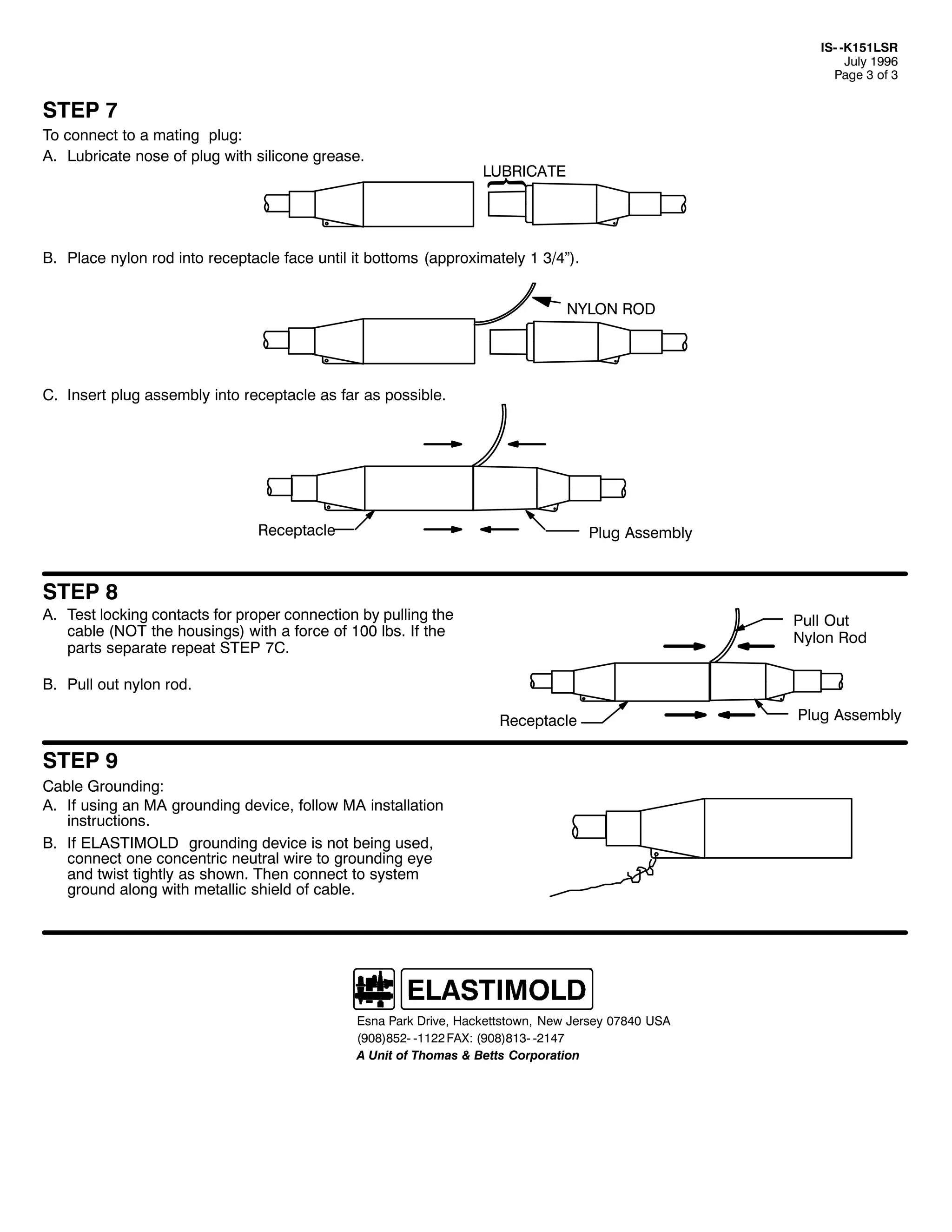
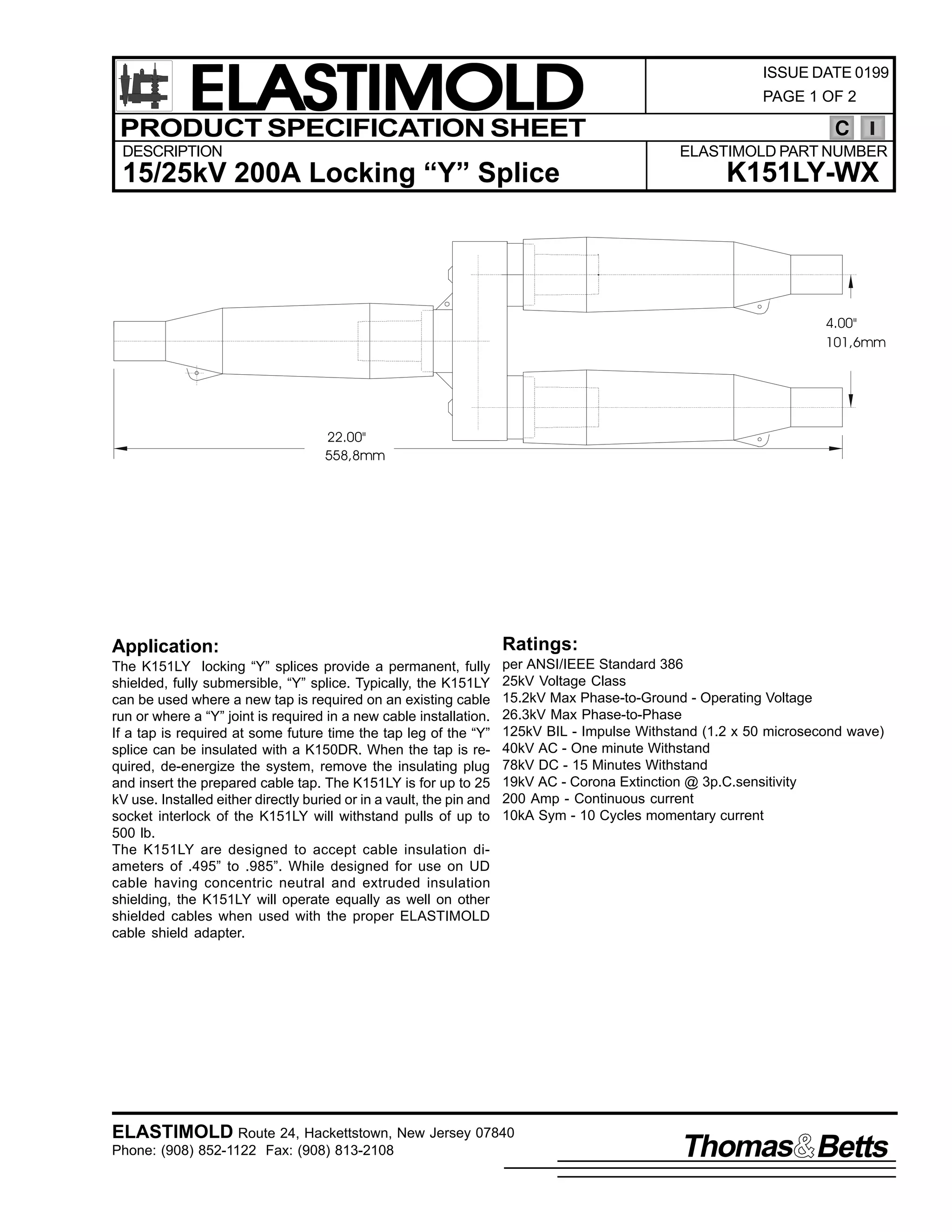
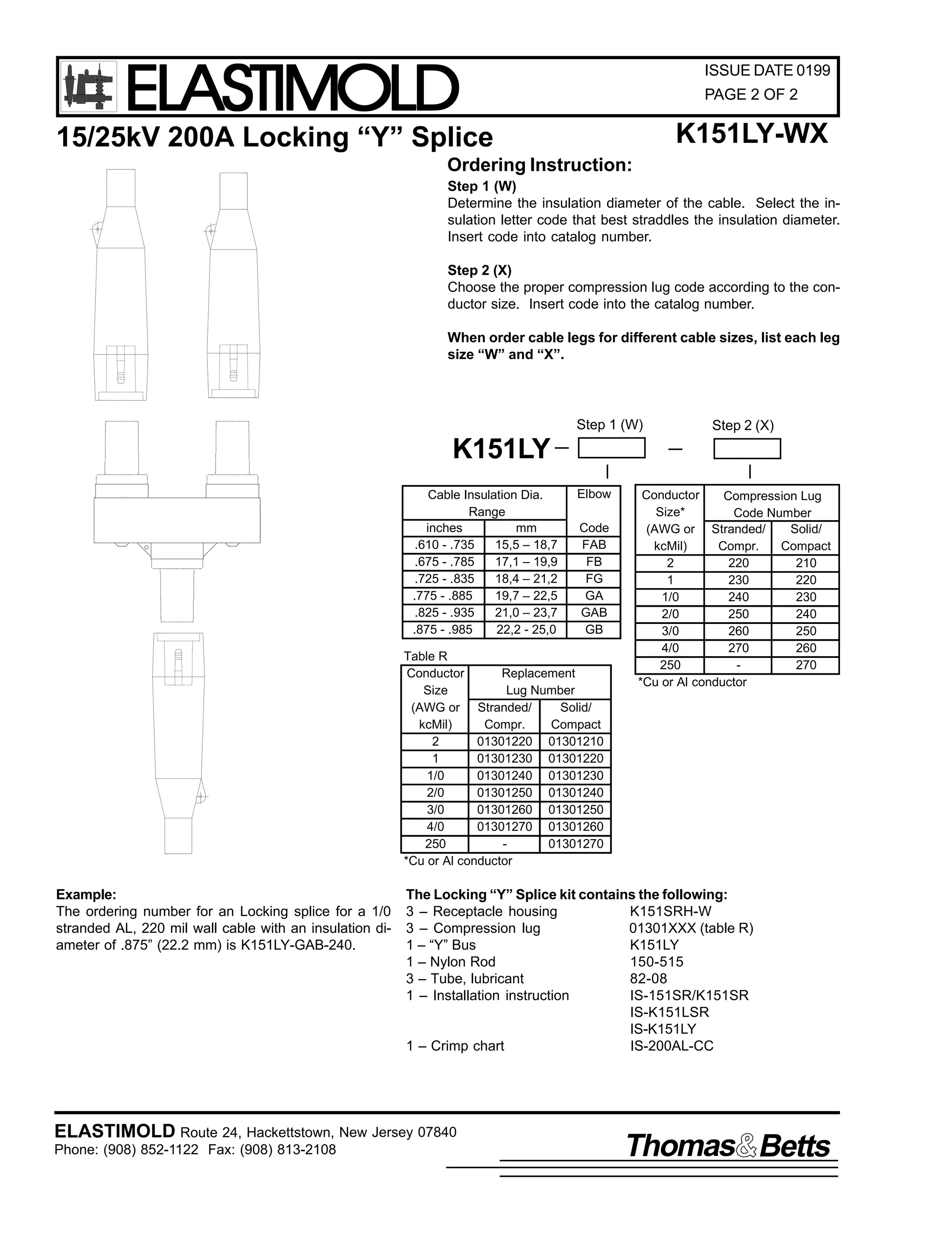

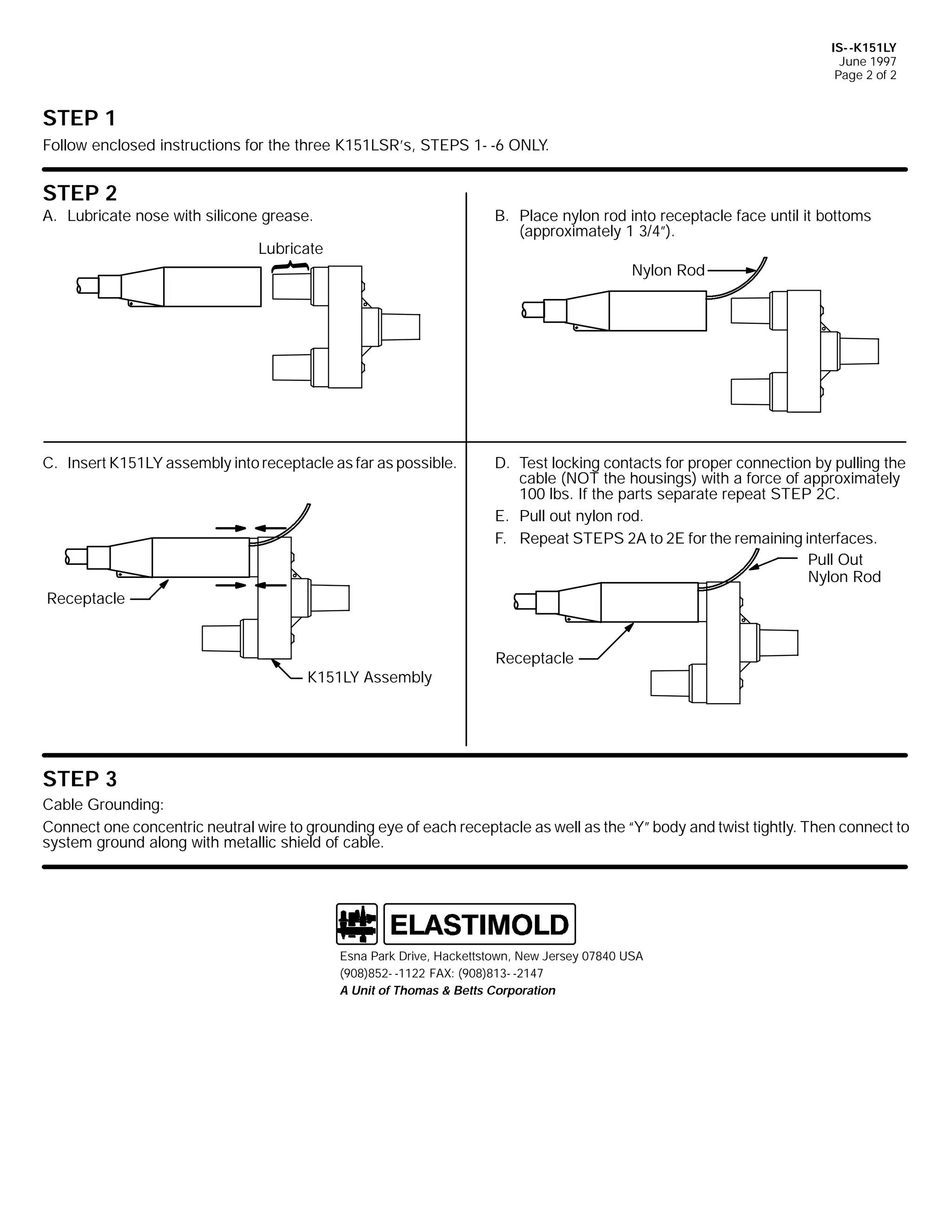
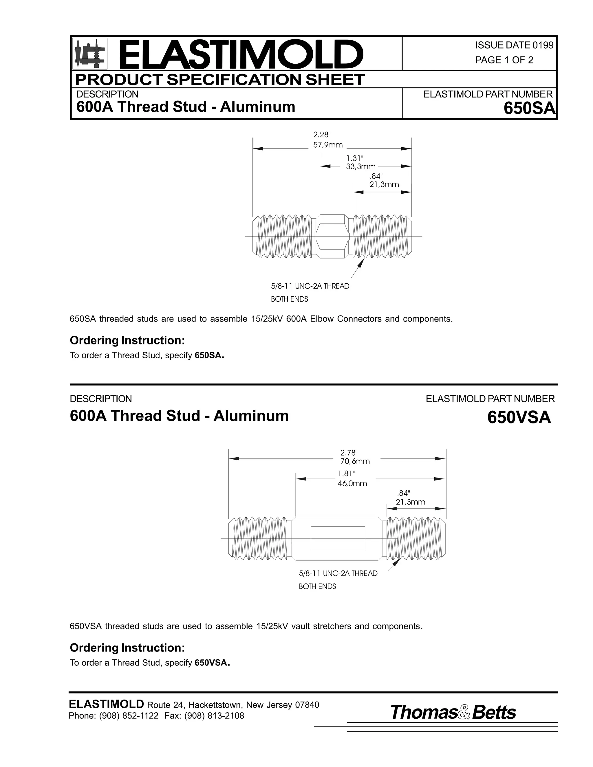
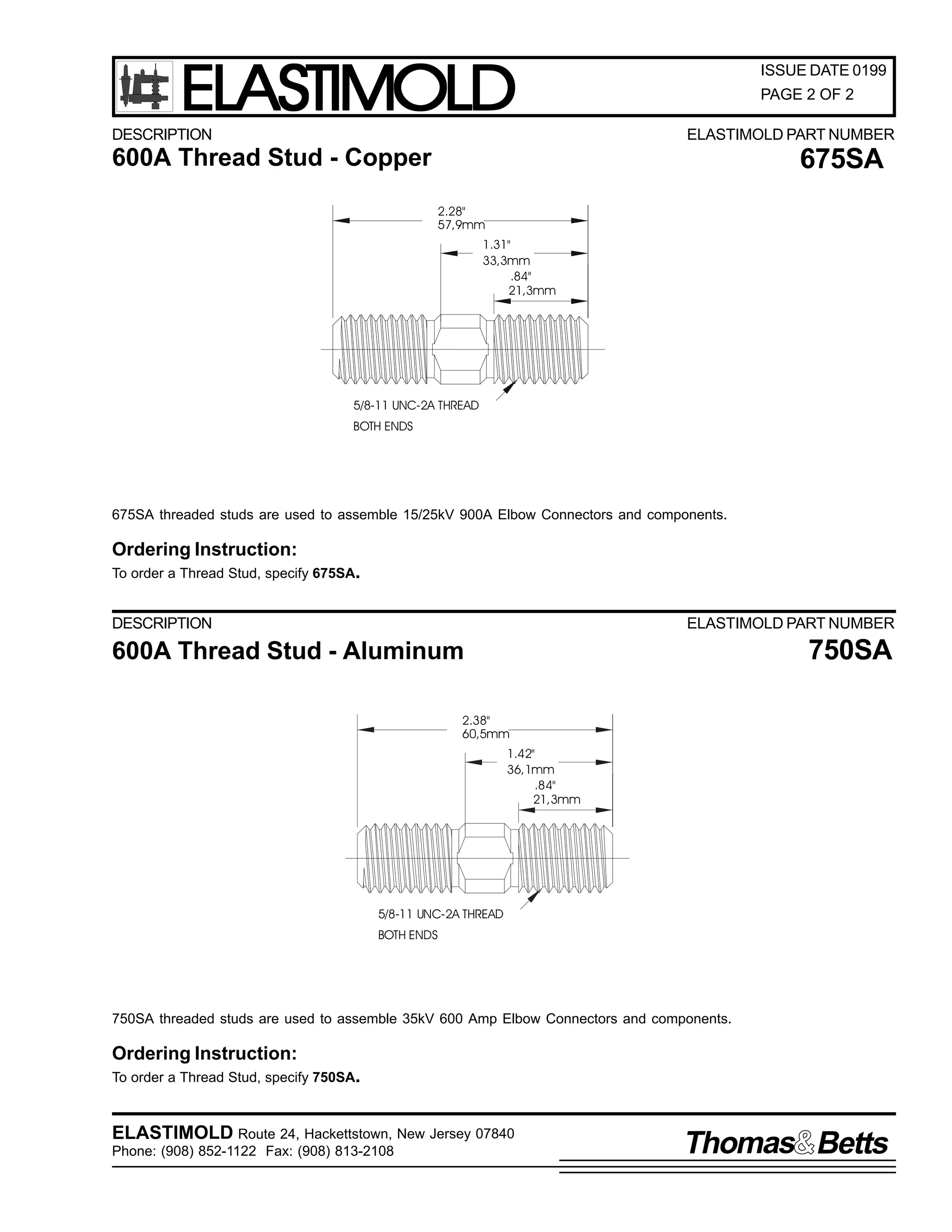

The document serves as a catalog for Elastimold's 5kV-35kV distribution products, detailing various product categories including separable connectors, cable joints, terminations, surge arresters, and loadbreak switches. It provides instructions for product selection, application information, and specifications including voltage ratings and current ratings, conforming to industry standards. Users can access component information and application guidelines through a structured layout of product pages and tables.


![Electromagnetic and-electronic-circuitbreaker-[technolead]](https://cdn.slidesharecdn.com/ss_thumbnails/electromagnetic-and-electronic-circuitbreaker-technolead-131119113212-phpapp01-thumbnail.jpg?width=640&height=640&fit=bounds)


