The document provides an overview of bone biomechanics concepts including:
- Mechanics concepts like statics, dynamics, and mechanics of materials and how they relate to bone.
- How knowledge of loads, deformations, stresses, and strains can be used to understand bone.
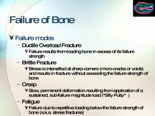
- Common failure modes in bone from excessive loading.
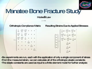
- An example application involving characterizing the fracture properties of manatee rib bones to understand boat collision impacts.


![F Static Analysis Resolve muscle force vector into x and y components useful angles Sum the forces and moments and set them equal to zero Use the figure to find the forces and moments in each direction Now let’s plug in some realistic values and solve for the forces What happens to F if we increase the moment arm, d? To Prof. Walsh W L d q f Rx Ry a b If W=20 lbf, L=14 in, d=0.5 in, =70°, and =50°: =70° F=687 lbf Rx=-235 lbf Ry=626 lbf If d=1 in F=343 lbf Rx=-117 lbf Ry=303 lbf =Rx+F*cos( ) Rx=-F*cos( ) =F*sin( )-W+Ry Ry=W-F*sin( ) =W*L*sin( )-d*F*sin( ) F=W*L*sin( )/[d*sin( )] + ∑Fx=0 + ∑Fy=0 + ∑M b =0 =90 ° - + y x](https://image.slidesharecdn.com/BoneBiomechanics-123064862859-phpapp01/85/Bone-Mechanics-Leismer-and-Walsh-2006-13-320.jpg)


![Stress-Strain Relationship: Constitutive Law Hooke’s Law { }=[C]{ ε } where [C] is the stiffness matrix { ε }=[S]{ }, where [S] is the compliance matrix Inverse relationship [S]=[C] -1 Material properties Elastic modulus = E Poisson’s ratio = Shear modulus = G To Jeff Anisotropy (21 elastic constants) Orthotropy (9 elastic constants) Transverse Isotropy (5 elastic constants) Isotropy (2 elastic constants)](https://image.slidesharecdn.com/BoneBiomechanics-123064862859-phpapp01/85/Bone-Mechanics-Leismer-and-Walsh-2006-20-320.jpg)


![Resources Contact Info: Email: [email_address] Phone: 920-287-1930 Web Profile: http://profile.jeffleismer.googlepages.com/ Books: Bone Mechanics Handbook (Cowin, 2001) Mechanical Testing of Bone (An & Draughn, 2000) WE HOPE YOU ENJOYED THE PRESENTATION PROFESSOR WALSH AND I WILL NOW TAKE THE REMAINING TIME TO ANSWER YOUR QUESTIONS](https://image.slidesharecdn.com/BoneBiomechanics-123064862859-phpapp01/85/Bone-Mechanics-Leismer-and-Walsh-2006-32-320.jpg)


![Biomechanics of stability pg course [recovered]](https://cdn.slidesharecdn.com/ss_thumbnails/biomechanicsofstabilitypgcourserecovered-200722004641-thumbnail.jpg?width=640&height=640&fit=bounds)


