Downloaded 29 times
![International Journal of Modern Engineering Research (IJMER)
www.ijmer.com Vol.3, Issue.1, Jan-Feb. 2013 pp-69-74 ISSN: 2249-6645
Comparison of Various Line Clipping Algorithm for Improvement
Abhishek Pandey1, Swati Jain2
1, 2
(Department: C.S.E., College Name: Takshshila Institute of Engineering and Technology, Country Name: India)
ABSTRACT: Demonstration of various Line clipping algorithms on the basis of their working principles. One way for
improving the efficiency of a line clipping algorithm is to reduce the repetition of algorithm. In this region codes are used to
identify the position of line. One algorithm reduces intersection calculations. An efficient clipping algorithm is presented
here to achieve this goal. One is based on testing xy plane to reduce intersection calculation. Our algorithm with reducing
the confluence point can avoid the repetition of algorithm.
Keywords: Line Clipping Algorithms, LB, CSL, NLN, Computer graphics.
I. INTRODUCTION
Any procedure, which identifies those portions of picture that are either inside or outside of the specified region of
the space is referred to as a clipping algorithm. The region against which an object is to clip is called a clip window.
Clipping algorithm can be applied in world coordinates so that only the contents of t6he window interior are mapped to the
device coordinates. There are five primitive types clipping, such as point, line, polygon or are, curve and text clipping.
Classical line clipping algorithms includes Cohen–Sutherland algorithm, Midpoint Subdivision algorithm, Liang Bearsky
and Nicholl-Lee-Nicholl algorithm.
Until recently, most works are concentrated on accelerating the intersection calculation so as to improve the
clipping efficiency [Sha92a, Day92a, Wan98a, Wan91a].
II. COHEN SUTHERLAND CLIPPING OVERVIEW
In computer graphics CSL algorithm is a line clipping algorithm. The algorithm divides the 2D space into 9 parts,
using the infinite extension of four linear boundaries of the window. Assign a bit pattern to each region as shown in figure.
CSL algorithm reputedly calculates intersections along a line path, even thought the line may be completely outside
the clip window and each calculation requires both a division and a multiplication.
Figure 1.1 Four bits code for nine region.
Above
Left Right
Below
The numbers in the figure above are called out codes. An out codes are computed for each of the two points in the
line. The bits in the out codes represent: TOP, BOTTOM, RIGHT, and LEFT. Each bit in the code is set to 1. If the region is
to the right of the window, the second bit of the code is set to 1. If the Bottom, third bit is set and if the Top, the fourth bit is
set. The four bits in the code the identify each of the nine region.
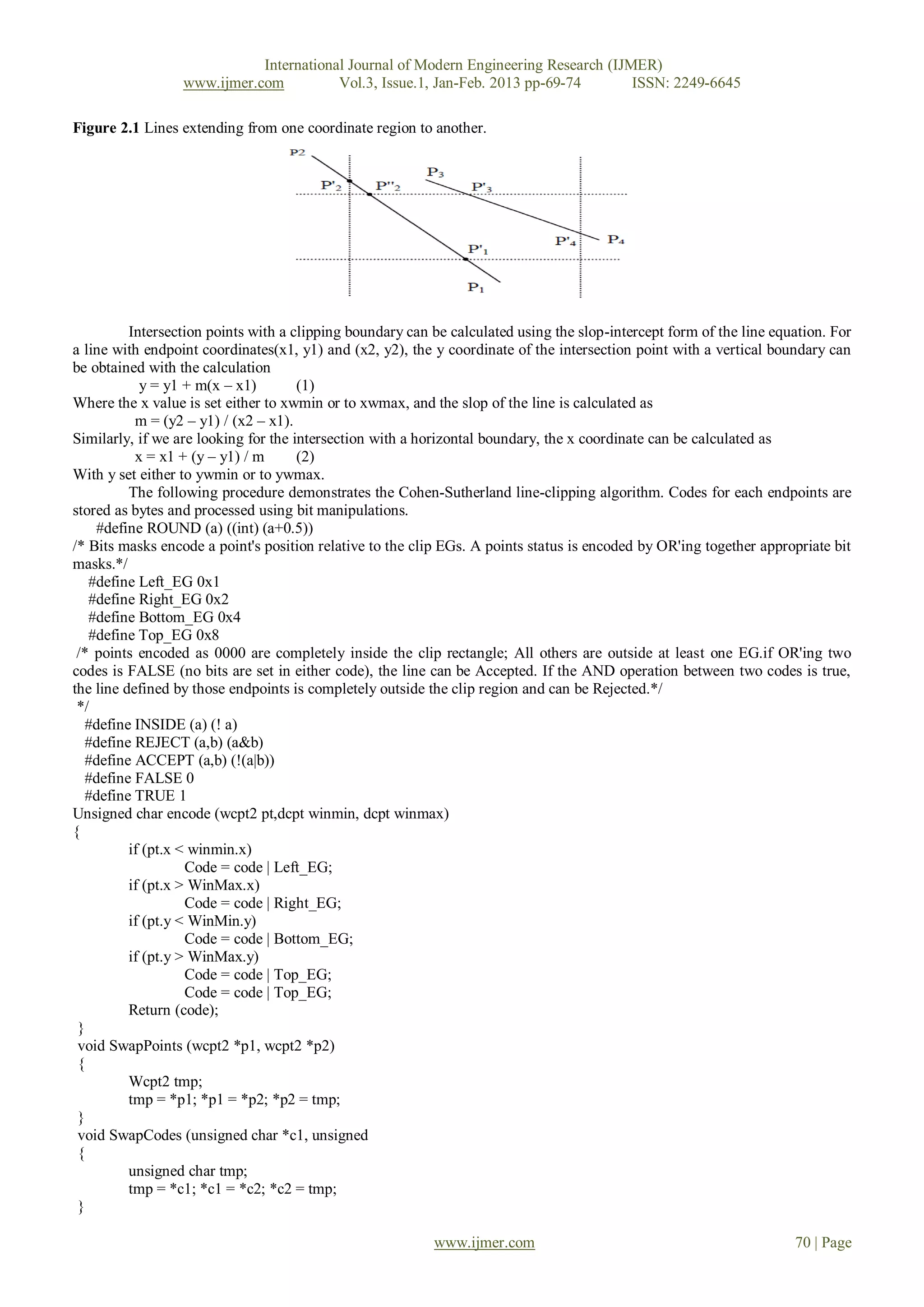
Lines that cannot be identified as completely inside or completely outside a clip window by these tests are checked
for intersection with the window boundaries. As shown in fig.2, such lines may or may not cross into the window interior.
We begin the clipping process for a line by comparing an outside endpoint to a clipping boundary to determine how much of
the line can be discarded. Then the remaining part of the line is checked against to other boundaries, and we continue until
either the line is totally discarded or a section is found outside the window. We set up our algorithm to checked line
endpoints against clipping boundaries in the order Left, Right, Bottom, and Top.
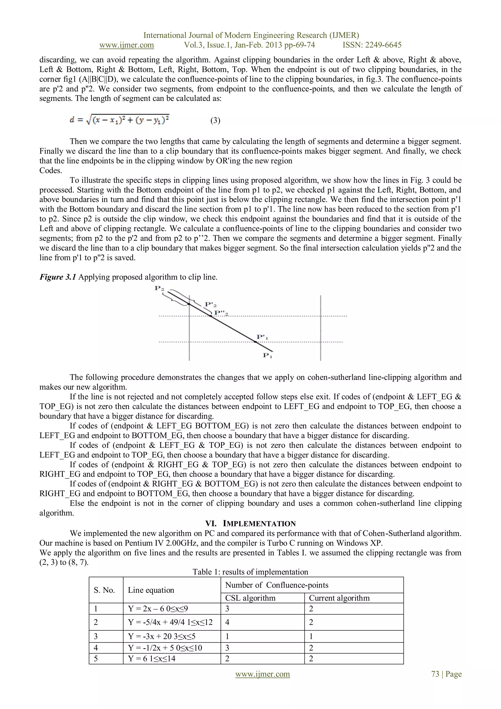
To illustrate the specific steps in clipping lines using the Cohen – Sutherland algorithm, we show how the lines in
Fig. 2 could be processed. Starting with the Bottom endpoint of the line from p1 to p2, we checked p1 against the Left,
Right, Bottom, and above boundaries in turn and find that this point is below the clipping rectangle. We then find the
intersection point p'1 with the Bottom boundary and discard the line section from p1 to p'1. The line now has been reduced to
the section from p'1 to p2. Since p2 is outside the clip window, we check this endpoint against the boundaries and find that it
is to the Left and above of the window. Intersection point p'2 is calculated. But this point is above the window. So the final
intersection calculation yields p''2 and the line from p'1 to p''2 is saved [Don04b].
www.ijmer.com 69 | Page](https://image.slidesharecdn.com/ak316974-130215013429-phpapp02/75/Comparison-of-Various-Line-Clipping-Algorithm-for-Improvement-1-2048.jpg)
![International Journal of Modern Engineering Research (IJMER)
www.ijmer.com Vol.3, Issue.1, Jan-Feb. 2013 pp-69-74 ISSN: 2249-6645
VII. RESULT
Certainly in best condition which the endpoints are completely inside or outside the clipping window, proposed
algorithm and Cohen-Sutherland algorithm are done the same. When endpoints are outside the clipping window and not in
the corner fig1 (A||B|C||D), these two algorithm line clip are similarly, because each endpoints are just out of one boundary
of clipping rectangle. Besides even if one of the endpoints be in the corner of clipping window, as you see in table.1, they
work different. When at least one endpoint be at the corner fig1 (A||B|C||D) our algorithm can done better. In this case the
average of confluence-points for Cohen-Sutherland algorithm may be three and two for our algorithm. Furthermore, if both
of endpoints be at the corner, the average of confluence-points may be four for Cohen-Sutherland algorithm and two for our
algorithm. As you see, in any condition our algorithm at most calculate just two confluence-points to line clipping. On the
other hand Cohen-Sutherland algorithm at most calculate four confluence- points. And as we said before whatever the
number of confluence-endpoints be lesser, the efficiency will be higher.
VIII. CONCLUSION
In this article we try to introduce a new algorithm that is based on Cohen -Sutherland algorithm. However when the
line endpoints be at the corner, our algorithm may perform better. As a whole the presented algorithm just by calculating at
most two confluence-points for the line in every condition can discard faster. We can extend this algorithm for the clipping
windows which even if they are not square. Moreover for increasing the accuracy of calculation we can use fuzzy.
IX. FUTURE WORK
Both CSL and LB can be extended to 3D clipping.
X. ACKNOWLEDGEMENT
This work received support from the Department of Computer Science & Engineering, Takshshila Institute of Engineering
and Technology.
BIOGRAPHIES
Abhishek Pandey B.E.[I.T.], M.E.[C.S.E] is an assistant professor in the Department of Computer Science, Takshshila
Institute of Technology, Jabalpur[M.P.], India. His research interests include computer graphics, data structure and software
engineering.
Swati Jain is an assistant professor in the Department of Computer Science, Takshshila Institute of Technology, Jabalpur
[M.P.], India. His research interests include computer graphics, Fuzzy Logics, Soft Computing and software engineering.
REFERENCES
[1] Donald Hearn, and M. Pauline Baker, “Computer Graphics, C Version”, 3 edition, pp. 226-230, December 2004.
[2] Goudong Lu*, Xuanhui Wu, Qunsheng Peng, “An efficient line clipping algorithm based o adaptive line rejection”, Computers &
Graphics 26 (2002) 409–415.
[3] Sharma NC, Manohar S. Line clipping revisited: two efficient algorithm basedon simple geometric observations. Computers and
Graphics 1992; 16(1): 51–4. Day JD. “A new two dimensional ling clipping algorithm for small windows”, Computer Graphics
Forum 1992; 11(4): 241–5.
[4] Wang Haohong, Wu Ruixun, Cai Shijie. “A new efficient clipping algorithm basedon geometric transformation”, Journal of
Software 1998; 9(10): 728–33 (in Chinese).
[5] Wang Jun, Liang Youdong, Peng Qunsheng. “A 2-D lineclipping with the least arithmetic operations”, Chinese Journal of
Computers 1991 ;( 7): 495–504(in chinese).
[6] Sproull RF, Sutherland IE. “A clipping divider”. In: Proceedings of the Fall Joint Computer Conference.Washington: Thompson
Books, 1968. p. 765–75.
[7] Rogers DF. “Procedural elements for computer graphics”. New York: McGraw-Hill, 1985. P.111–87.
[8] Sobkow MS, Pospisil P, Yang YH. A fast two-dimensional line clipping algorithm via line encoding Computers and Graphics198.
www.ijmer.com 74 | Page](https://image.slidesharecdn.com/ak316974-130215013429-phpapp02/75/Comparison-of-Various-Line-Clipping-Algorithm-for-Improvement-6-2048.jpg)

The document compares various line clipping algorithms and proposes an improved Cohen-Sutherland algorithm. It summarizes Cohen-Sutherland, Liang-Bersky, and Nichol-Lee-Nichol algorithms. The improved Cohen-Sutherland algorithm aims to reduce repetition by avoiding recalculation of intersection points when an endpoint is at a clipping boundary corner. It does this by comparing distances to clipping boundaries and discarding along the further boundary segment. The algorithm is presented as having fewer intersection calculations than standard Cohen-Sutherland clipping.