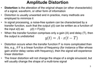
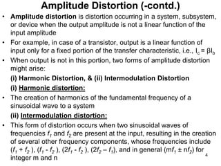
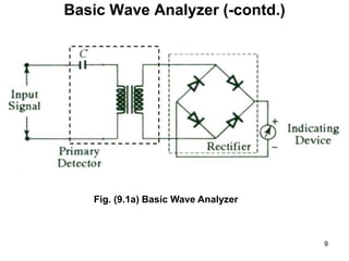
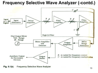
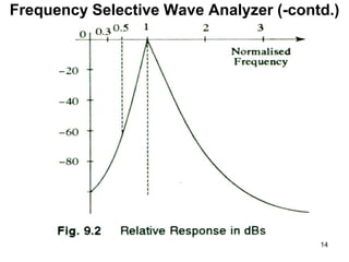
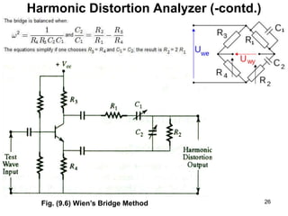
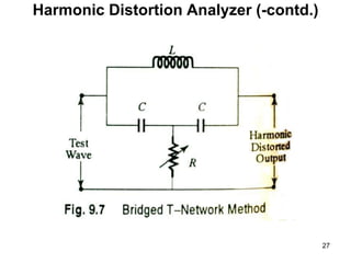
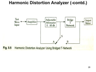
The document discusses various types of instruments used to measure amplitude distortion in electronic systems, including wave analyzers, harmonic distortion analyzers, and heterodyne wave analyzers. It describes how amplitude distortion occurs when the output amplitude is not a linear function of the input amplitude. It also explains the different types of amplitude distortion, such as harmonic distortion and intermodulation distortion, and how instruments like wave analyzers can be used to measure the amplitude of individual harmonics. The document provides details on the basic design and operation of different wave analyzer circuits, including basic, frequency selective, and heterodyne wave analyzers. It concludes by mentioning harmonic distortion analyzers can measure total harmonic distortion without measuring individual harmonics.
This document summarizes a dual input balanced output differential amplifier circuit. It consists of two matched transistors (T1 and T2) with their emitters joined to a constant current source. It has two input signals (V1 and V2) applied to the transistor bases. The output is measured between the two collectors (C1 and C2), which are at the same DC potential with respect to ground, giving a balanced output. The AC equivalent circuit is used to determine the voltage gain and input resistance of the differential amplifier. Key advantages are high gain without needing additional stages and removal of lower cut-off frequencies. An application is as a subtractor circuit.
The document discusses streamer theory of gas breakdown, which addresses some limitations of Townsend's theory. It explains that streamer theory involves additional mechanisms like photoionization and space charge effects. The total time lag of breakdown has two components - statistical time lag and formative time lag. An avalanche develops across the gap due to ionization, leaving a positive space charge. Secondary avalanches form near the anode due to field enhancement. As the streamer crosses the gap, a conducting channel is formed. Streamer theory predicts faster breakdown times and dependence on pressure/geometry compared to Townsend's theory.
This presentation summarizes an operational amplifier based function generator that can produce sine, square, triangular, and sawtooth waveforms. It describes the working of the square wave generator using an op-amp and capacitor to charge and discharge, producing a switching output. A triangular wave is generated by charging and discharging a capacitor with a constant current. This triangular wave can then be shaped into a sine wave using a diode clipping circuit. The function generator can output different frequencies and amplitudes and is used to test electronic equipment.
1. The document discusses different types of oscillators including RC oscillators and the Wein bridge oscillator.
2. A Wein bridge oscillator uses two transistor amplifier stages to provide a total phase shift of 360 degrees, with feedback to the oscillatory circuit to produce undamped oscillations.
3. The frequency of oscillations in a Wein bridge oscillator is determined by the RC elements in the bridge circuit.
low pass filters in detail
Low Pass Filters
RC Low Pass Filter
Critical or cutoff frequency
Response curve
Cutoff frequency of RC LPF
RL Low Pass Filter
Cutoff Frequency of RL LPF
Phase Response in Low Pass Filter
An amplifier is one of the most important applications of transistor. Generally, transistor in CE configuration was used for faithful amplification of signal due to high gain, high input impedance and high power gain. But it has been observed that feedback in an amplifier introduces significant improvement in gain and gives amplified output in required form.
This document provides instructions for designing an RC phase shift oscillator using an operational amplifier to produce an output frequency of 200 Hz. It explains that the circuit uses three RC cascaded networks in the feedback path to provide a total of 360 degrees of phase shift, along with inversion from the op-amp, allowing oscillations. The procedure involves constructing the circuit as shown, adjusting the potentiometer to obtain the output waveform, measuring the frequency and voltage, and comparing the theoretical and experimental frequency values.
The document discusses the cathode ray oscilloscope (CRO). It begins with an introduction that describes a CRO as an electronic device that uses a cathode ray tube to generate visible patterns and graphs on a screen. It then provides details about the basic blocks of a CRO including the vertical and horizontal amplifiers, trigger circuit, time-base generator, and cathode ray tube. Applications of CROs include viewing waveforms, measuring frequency and voltage, and circuit design and testing. Advantages include high resolution and contrast while disadvantages include size, power consumption, and complexity.
This document discusses unsymmetrical faults in power systems. Unsymmetrical faults occur when a fault creates an imbalance in the system. There are three types of unsymmetrical faults: single line to ground fault, line to line fault, and double line to ground fault. Unsymmetrical faults can be analyzed using a bus impedance matrix that represents the positive, negative, and zero sequence network equivalents. The sequence components of the fault current are then calculated based on the voltage and appropriate sequence impedance terms for each type of fault.
Este documento describe los sistemas de primer y segundo orden, incluyendo circuitos eléctricos, diagramas de bloques, funciones de transferencia y respuestas a diferentes estímulos. Para los sistemas de primer orden se analiza la respuesta a una entrada de escalón unitario, mientras que para los sistemas de segundo orden se presenta la función de transferencia general y los casos de amortiguamiento subcrítico, crítico y sobreamortiguado. El documento también incluye ejemplos de simulación en Proteus e ISIS.
A wave analyzer is an instrument designed to measure relative amplitudes of single frequency components in a complex waveform. Basically, a wave instrument acts as a frequency selective voltmeter which is tuned to the frequency of one signal while rejecting all other signal components.
An oscilloscope is an instrument that displays electrical signals as a graph over time. It consists of major blocks including a cathode ray tube (CRT), vertical amplifier, time base generator, horizontal amplifier, and power supply. The vertical amplifier amplifies input signals and sends them to the CRT. The time base generator produces a sawtooth waveform to control the horizontal sweep of the electron beam on the CRT. The horizontal amplifier further amplifies this signal before sending it to the horizontal deflection plates of the CRT. Together these components allow the oscilloscope to visualize signals and measure their characteristics.
This document provides an overview of amplifiers:
1. An amplifier is an electronic device that increases the magnitude of a signal applied to its input. Amplifiers are commonly used to amplify small input signals to drive speakers, lamps, or other loads.
2. Amplifiers can be classified by their configuration (common emitter, base, or collector), class of operation (A, B, C, or AB), and frequency of operation (DC, AF, RF, VHF, UHF, or SHF). Different types of amplifier gain include voltage, current, and power gain.
3. Power amplifiers are amplifiers that deliver relatively high power, usually to a low resistance
Differential amplifiers amplify the difference between two input signals while rejecting input signals that are common to both inputs. They have advantages like excellent stability, versatility, and immunity to noise and interference. The differential gain (Ad) is the gain with which the difference between the two input signals (V1-V2) is amplified to produce the output (Vo). The common mode gain (Ac) is the gain resulting from any common signals applied to both inputs. Differential amplifiers have high differential gain, low common mode gain, and high common mode rejection ratio (CMRR), which is the ratio of Ad/Ac expressed in decibels and indicates the ability to reject common mode signals.
dso is use for measurement ac as well as dc voltage and current.
and also use for faulty components in various circuit .it stored wave form in digital memory.it easy to operate. cursor measurement is possible.
The document repeatedly discusses potentiometers and magnetic measurements without providing any details about them. It appears to be about electrical measurement devices but does not explain what they are or how they are used.
This document discusses the key ratings of silicon controlled rectifiers (SCRs) that must be considered for reliable operation. It outlines voltage ratings like peak repetitive forward blocking voltage and peak working reverse voltage. It also covers current ratings like maximum average current rating and di/dt rating. Thermal ratings like the I2t rating and maximum junction temperature are provided. The document emphasizes that SCRs must operate within these specified ratings to avoid damage.
Oscillators introduction and its types, phase shift oscillators and wein bridge oscillators,difference between phase shift and wein bridge, frequency stability, oscillators principle and conditions, block diagram of oscillators, block diagram of phase shift oscillators
torque equation for polyphase induction motor Pankaj Nakum
1. The torque produced by a three-phase induction motor depends on the rotating magnetic field interacting with the rotor, the magnitude of the rotor current, and the power factor of the rotor circuit.
2. The equation for torque is proportional to the flux, rotor current, and the cosine of the power factor angle.
3. Maximum torque occurs when the slip is equal to the ratio of rotor resistance to reactance.
Three phase transformers have three sets of primary and secondary windings that can be connected in either a star or delta configuration. The vector group of a transformer indicates the phase difference between the primary and secondary windings, which is important when connecting multiple transformers in parallel. Vector groups use letters and numbers to denote the winding configuration and phase displacement between windings. Zigzag transformers contain six coils on three cores and can cancel certain harmonic currents.
Function generators are electronic test equipment that generate common waveforms like sine, square, and triangular waves over a wide frequency range. They are used to test and develop electronic equipment. Simple function generators generate waveforms by charging and discharging a capacitor with a constant current source, while more advanced arbitrary waveform generators can produce any digitally defined shape using direct digital synthesis techniques. Function generators provide important features like continuous tuning over a broad frequency band, modulation capabilities, and the ability to sweep output frequencies.
The document discusses various triggering circuits used for thyristors and SCRs. It describes R-triggering circuits which use a resistor in the gate circuit to control firing angle. RC triggering circuits use a capacitor to discharge through the gate for improved firing control. Unijunction transistor (UJT) based triggering circuits can control firing angle up to 180 degrees. UJT characteristics and relaxation oscillator design are covered. Forced commutation methods like pulse transformers and optical isolation are discussed for turning off thyristors in DC circuits.
Thyristors require commutation to turn off, which involves reducing the anode current to zero and then applying a reverse voltage for a time. There are natural and forced commutation methods. Forced methods include classes A through F, which use resonant circuits, auxiliary thyristors, or line voltage reversals to commutate the main thyristor. Turn off time has two stages - reverse recovery time to remove outer layer carriers, then gate recovery time for inner layer recombination. Proper commutation circuit design is needed to apply reverse voltage for longer than the thyristor's turn off time.
Construction & E.M.F. eqn. of transformerJay Baria
In this ppt, construction and emf equation of transformer is shown and also the types of transformer and its various losses and its application is given in the presentation.
Inverter is a device which convert a DC input supply voltage into symmetric AC voltage of desired magnitude and frequency at the output side. It is also know as DC-AC converter.
Ideal and practical inverter have sinusoidal and no-sinusoidal waveforms at output respectively.
If the input dc is a voltage source, the inverter is called a Voltage Source Inverter (VSI). One can similarly think of a Current Source Inverter (CSI), where the input to the circuit is a current source. The VSI circuit has direct control over ‘output (ac) voltage’ whereas the CSI directly controls ‘output (ac) current.
EMI unit-2 signal generators and signal analyzersGopalakrishnaU
This document describes the components and operation of different types of wave analyzers. A basic wave analyzer consists of a tuned LC circuit detector, full-wave rectifier, and DC voltmeter. Frequency selective wave analyzers use adjustable filters to select single frequencies within the audio range. Heterodyne wave analyzers mix the input signal with a local oscillator signal to shift it to a fixed intermediate frequency for amplification and measurement. Harmonic distortion analyzers suppress the fundamental frequency to measure the total harmonic content as a distortion percentage.
Spectrum analyzers measure the magnitude and frequency of input signals. There are two main types: Fourier transform analyzers which use digital signal processing to analyze the entire frequency range simultaneously, and swept-tuned analyzers which use analog filters to sweep through the frequency range. Key specifications for spectrum analyzers include frequency range, amplitude range and sensitivity to measure small signals, resolution bandwidth to distinguish closely spaced frequencies, and dynamic range to measure large and small signals simultaneously.
Vibration signals can be filtered using various filter types to isolate different frequency bands. Active filters use op-amps and transistors while passive filters use inductors, capacitors, and resistors. Filter types include low-pass, high-pass, band-pass, and band-stop filters based on the frequencies allowed. Filter designs like Butterworth, Chebyshev, and elliptic provide different frequency responses. Spectrum analysis separates a signal into its frequency components using filters. Fast Fourier transforms allow real-time analysis by rapidly converting time signals to frequency spectra.
- FM signals are demodulated by detecting the instantaneous frequency, which can be done with an ideal differentiator or high-pass filter that outputs a signal proportional to frequency.
- In a superheterodyne receiver, the incoming RF signal is mixed with a local oscillator signal to convert it to a fixed intermediate frequency (IF) for amplification and detection. This allows for good selectivity through tuning of the IF filters.
- Common demodulators include discriminators, ratio detectors, and zero-crossing detectors, with the amplitude limiter generating a rectangular pulse train for the zero-crossing detector.
This document discusses different types of signal analyzers used for frequency domain analysis: distortion analyzers, wave analyzers, and spectrum analyzers. Distortion analyzers measure harmonic distortion by quantifying the magnitudes of the fundamental frequency and harmonic multiples. Wave analyzers can measure individual harmonic amplitudes by using a tunable filter to examine portions of the frequency spectrum. Heterodyne-type wave analyzers mix the input signal with a variable oscillator signal to produce sum and difference frequencies that can be analyzed. These instruments provide valuable information about electrical and mechanical systems through analysis of signals in the frequency domain.
1) An FM demodulator is an electronic circuit that recovers the original information from a modulated carrier wave by converting frequency variations to amplitude variations using a tuned circuit, and then extracting the information using AM demodulation techniques.
2) Common types of FM demodulators include indirect (slope detector) and direct (foster-seeley, ratio detector) methods. The basic FM demodulator is a slope detector which uses a tuned LC circuit to convert frequency variations to amplitude variations for detection.
3) A balanced slope detector improves on a basic slope detector by using two tuned circuits connected back-to-back to opposite ends of a transformer to provide better linearity but at
The document summarizes transmitters and receivers. It describes different types of transmitters including AM and FM transmitters. It discusses components of transmitters like modulators, amplifiers, and transmission antennas. It also covers different types of receivers including tuned radio frequency (TRF) receivers and superheterodyne receivers. It provides details on components of receivers like RF sections, intermediate frequency amplifiers, and automatic gain control. It compares AM and FM receivers and discusses amplitude limiting in FM receivers.
A spectrum analyzer is a device that examines the spectral composition of electrical signals. It uses a mixer to convert the input signal to an intermediate frequency, then filters, amplifies, and detects this signal. Spectrum analyzers can operate in either swept or FFT modes. Swept analyzers use a local oscillator that is swept through a range of frequencies, while FFT analyzers use digital signal processing to compute the fast Fourier transform. The analyzer displays the amplitude of the signal versus frequency, allowing users to analyze signals in the frequency domain.
In this presentation we discuss about the active filters and mentioned its frequency response along with block diagrams. Also discussed its pros and cons in this presentation.
This document provides information about wave analyzers and harmonic distortion analyzers. It discusses the basic components and functions of a basic wave analyzer, which consists of a primary detector, full wave rectifier, and galvanometer. It also describes frequency selective and heterodyne wave analyzers. The document then covers harmonic distortion analyzers, defining total harmonic distortion as a percentage based on harmonic and fundamental signal amplitudes. It provides an example calculation and discusses how harmonic distortion analyzers measure THD using filters to separate the fundamental and harmonic components.
Description about -
1.filter and types of filter
2.comb filter defination & its magnitude and phase response
3.Digital comb filter defination & its magnitude and phase response
4.Digital comb filter using a digital differentiator & its magnitude and phase response
5.Comb Filters with Multiple Delay Elements defination & its magnitude and phase response
6.Digital Integrator(non-delaying) defination & its magnitude and phase response
7.Delaying Integrator defination & its magnitude and phase response
8.Fourier Transform & Dirac Delta Function (Unit Impulse Response) and its properties
The document discusses the components and operation of a spectrum analyzer. It describes:
- Major blocks of a spectrum analyzer including the RF input, mixer, IF gain, IF filter, detector, video filter, local oscillator, sweep generator, and display.
- How these blocks work together to convert an input signal to different frequencies, select specific frequencies using filters, detect the signals, and display the results on screen.
- Functions of the front panel including setting frequency, amplitude, resolution bandwidth, sweep time, and input attenuation.
- How spectrum analyzers can be used to analyze signals and characterize devices under test by adjusting settings like frequency and resolution bandwidth.
A sweep frequency generator is a type of signal generator that generates a sinusoidal output signal whose frequency is automatically varied or swept between two selected frequencies. It uses two oscillators - a master oscillator that produces a constant frequency and a voltage-controlled oscillator whose frequency varies. A mixer combines the outputs of the two oscillators to produce a sinusoidal output whose frequency is swept between the frequencies of the two oscillators. Sweep frequency generators are primarily used to measure the responses of amplifiers, filters, and other electrical components over various frequency bands.
A sweep frequency generator generates a sinusoidal output whose frequency is automatically varied or swept between two selected frequencies. One complete cycle of the frequency variation is called a sweep. Sweep frequency generators are primarily used to measure the responses of amplifiers, filters, and electrical components over various frequency bands. The frequency is varied either linearly or logarithmically over the entire sweep range, while the signal amplitude remains constant.
The document describes the components and functioning of a superheterodyne receiver. It explains that the receiver transforms RF signals into an intermediate frequency (IF) signal using a mixer and local oscillator, then amplifies and demodulates the IF signal to extract video information. It outlines the key components - antenna, filter, mixer, IF amplifier, detector, video amplifier and local oscillator - and describes the heterodyning process used to shift signals to the IF. It also discusses issues like image frequency interference that can occur without a pre-amplifier and how components work to address this.
This document provides an overview of various types of signal generators and signal analyzers used in electronics. It describes the basic components and functions of audio and radio frequency signal generators, function generators, square wave and pulse generators. It also discusses considerations for choosing a signal generator such as frequency range, output voltage, resolution, accuracy, and stability. Signal analyzers described include audio/radio frequency wave analyzers, harmonic distortion analyzers, and spectrum analyzers.
This document provides information about transmitter and receiver block diagrams for radio communication systems. It discusses:
- The basic components and signal flow in an AM transmitter, including a pre-amplifier, RF oscillator, modulator, and power amplifier.
- The similar components and signal flow in an FM transmitter, with the addition of a high pass filter and frequency multiplier stages.
- The operation of a superheterodyne receiver, including components like an antenna, RF amplifier, mixer, local oscillator, IF amplifier, detector, and audio amplifier to downconvert, amplify and detect the modulated signal.
- Additional concepts like receiver sensitivity, signal-to-noise ratio, and the Friis transmission equation for
The document discusses filters and attenuators. It describes filters as electrical circuits that can modify, reshape, or reject unwanted frequencies from an electrical signal, passing only desired signals. Filters are classified as low-pass, high-pass, band-pass, and band-stop based on which frequency bands they allow to pass. Characteristic impedance is real in pass bands and imaginary in stop bands. Constant-k and m-derived filters including low-pass, high-pass, band-pass, and band-stop filters are also covered qualitatively. Attenuators are discussed qualitatively as being symmetrical or asymmetrical.
Electric vehicle and photovoltaic advanced roles in enhancing the financial p...IJECEIAES
Climate change's impact on the planet forced the United Nations and governments to promote green energies and electric transportation. The deployments of photovoltaic (PV) and electric vehicle (EV) systems gained stronger momentum due to their numerous advantages over fossil fuel types. The advantages go beyond sustainability to reach financial support and stability. The work in this paper introduces the hybrid system between PV and EV to support industrial and commercial plants. This paper covers the theoretical framework of the proposed hybrid system including the required equation to complete the cost analysis when PV and EV are present. In addition, the proposed design diagram which sets the priorities and requirements of the system is presented. The proposed approach allows setup to advance their power stability, especially during power outages. The presented information supports researchers and plant owners to complete the necessary analysis while promoting the deployment of clean energy. The result of a case study that represents a dairy milk farmer supports the theoretical works and highlights its advanced benefits to existing plants. The short return on investment of the proposed approach supports the paper's novelty approach for the sustainable electrical system. In addition, the proposed system allows for an isolated power setup without the need for a transmission line which enhances the safety of the electrical network
An improved modulation technique suitable for a three level flying capacitor ...IJECEIAES
This research paper introduces an innovative modulation technique for controlling a 3-level flying capacitor multilevel inverter (FCMLI), aiming to streamline the modulation process in contrast to conventional methods. The proposed
simplified modulation technique paves the way for more straightforward and
efficient control of multilevel inverters, enabling their widespread adoption and
integration into modern power electronic systems. Through the amalgamation of
sinusoidal pulse width modulation (SPWM) with a high-frequency square wave
pulse, this controlling technique attains energy equilibrium across the coupling
capacitor. The modulation scheme incorporates a simplified switching pattern
and a decreased count of voltage references, thereby simplifying the control
algorithm.
Advanced control scheme of doubly fed induction generator for wind turbine us...IJECEIAES
This paper describes a speed control device for generating electrical energy on an electricity network based on the doubly fed induction generator (DFIG) used for wind power conversion systems. At first, a double-fed induction generator model was constructed. A control law is formulated to govern the flow of energy between the stator of a DFIG and the energy network using three types of controllers: proportional integral (PI), sliding mode controller (SMC) and second order sliding mode controller (SOSMC). Their different results in terms of power reference tracking, reaction to unexpected speed fluctuations, sensitivity to perturbations, and resilience against machine parameter alterations are compared. MATLAB/Simulink was used to conduct the simulations for the preceding study. Multiple simulations have shown very satisfying results, and the investigations demonstrate the efficacy and power-enhancing capabilities of the suggested control system.
Null Bangalore | Pentesters Approach to AWS IAMDivyanshu
#Abstract:
- Learn more about the real-world methods for auditing AWS IAM (Identity and Access Management) as a pentester. So let us proceed with a brief discussion of IAM as well as some typical misconfigurations and their potential exploits in order to reinforce the understanding of IAM security best practices.
- Gain actionable insights into AWS IAM policies and roles, using hands on approach.
#Prerequisites:
- Basic understanding of AWS services and architecture
- Familiarity with cloud security concepts
- Experience using the AWS Management Console or AWS CLI.
- For hands on lab create account on [killercoda.com](https://killercoda.com/cloudsecurity-scenario/)
# Scenario Covered:
- Basics of IAM in AWS
- Implementing IAM Policies with Least Privilege to Manage S3 Bucket
- Objective: Create an S3 bucket with least privilege IAM policy and validate access.
- Steps:
- Create S3 bucket.
- Attach least privilege policy to IAM user.
- Validate access.
- Exploiting IAM PassRole Misconfiguration
-Allows a user to pass a specific IAM role to an AWS service (ec2), typically used for service access delegation. Then exploit PassRole Misconfiguration granting unauthorized access to sensitive resources.
- Objective: Demonstrate how a PassRole misconfiguration can grant unauthorized access.
- Steps:
- Allow user to pass IAM role to EC2.
- Exploit misconfiguration for unauthorized access.
- Access sensitive resources.
- Exploiting IAM AssumeRole Misconfiguration with Overly Permissive Role
- An overly permissive IAM role configuration can lead to privilege escalation by creating a role with administrative privileges and allow a user to assume this role.
- Objective: Show how overly permissive IAM roles can lead to privilege escalation.
- Steps:
- Create role with administrative privileges.
- Allow user to assume the role.
- Perform administrative actions.
- Differentiation between PassRole vs AssumeRole
Try at [killercoda.com](https://killercoda.com/cloudsecurity-scenario/)
Comparative analysis between traditional aquaponics and reconstructed aquapon...bijceesjournal
The aquaponic system of planting is a method that does not require soil usage. It is a method that only needs water, fish, lava rocks (a substitute for soil), and plants. Aquaponic systems are sustainable and environmentally friendly. Its use not only helps to plant in small spaces but also helps reduce artificial chemical use and minimizes excess water use, as aquaponics consumes 90% less water than soil-based gardening. The study applied a descriptive and experimental design to assess and compare conventional and reconstructed aquaponic methods for reproducing tomatoes. The researchers created an observation checklist to determine the significant factors of the study. The study aims to determine the significant difference between traditional aquaponics and reconstructed aquaponics systems propagating tomatoes in terms of height, weight, girth, and number of fruits. The reconstructed aquaponics system’s higher growth yield results in a much more nourished crop than the traditional aquaponics system. It is superior in its number of fruits, height, weight, and girth measurement. Moreover, the reconstructed aquaponics system is proven to eliminate all the hindrances present in the traditional aquaponics system, which are overcrowding of fish, algae growth, pest problems, contaminated water, and dead fish.
Rainfall intensity duration frequency curve statistical analysis and modeling...bijceesjournal
Using data from 41 years in Patna’ India’ the study’s goal is to analyze the trends of how often it rains on a weekly, seasonal, and annual basis (1981−2020). First, utilizing the intensity-duration-frequency (IDF) curve and the relationship by statistically analyzing rainfall’ the historical rainfall data set for Patna’ India’ during a 41 year period (1981−2020), was evaluated for its quality. Changes in the hydrologic cycle as a result of increased greenhouse gas emissions are expected to induce variations in the intensity, length, and frequency of precipitation events. One strategy to lessen vulnerability is to quantify probable changes and adapt to them. Techniques such as log-normal, normal, and Gumbel are used (EV-I). Distributions were created with durations of 1, 2, 3, 6, and 24 h and return times of 2, 5, 10, 25, and 100 years. There were also mathematical correlations discovered between rainfall and recurrence interval.
Findings: Based on findings, the Gumbel approach produced the highest intensity values, whereas the other approaches produced values that were close to each other. The data indicates that 461.9 mm of rain fell during the monsoon season’s 301st week. However, it was found that the 29th week had the greatest average rainfall, 92.6 mm. With 952.6 mm on average, the monsoon season saw the highest rainfall. Calculations revealed that the yearly rainfall averaged 1171.1 mm. Using Weibull’s method, the study was subsequently expanded to examine rainfall distribution at different recurrence intervals of 2, 5, 10, and 25 years. Rainfall and recurrence interval mathematical correlations were also developed. Further regression analysis revealed that short wave irrigation, wind direction, wind speed, pressure, relative humidity, and temperature all had a substantial influence on rainfall.
Originality and value: The results of the rainfall IDF curves can provide useful information to policymakers in making appropriate decisions in managing and minimizing floods in the study area.
Introduction- e - waste – definition - sources of e-waste– hazardous substances in e-waste - effects of e-waste on environment and human health- need for e-waste management– e-waste handling rules - waste minimization techniques for managing e-waste – recycling of e-waste - disposal treatment methods of e- waste – mechanism of extraction of precious metal from leaching solution-global Scenario of E-waste – E-waste in India- case studies.
Redefining brain tumor segmentation: a cutting-edge convolutional neural netw...IJECEIAES
Medical image analysis has witnessed significant advancements with deep learning techniques. In the domain of brain tumor segmentation, the ability to
precisely delineate tumor boundaries from magnetic resonance imaging (MRI)
scans holds profound implications for diagnosis. This study presents an ensemble convolutional neural network (CNN) with transfer learning, integrating
the state-of-the-art Deeplabv3+ architecture with the ResNet18 backbone. The
model is rigorously trained and evaluated, exhibiting remarkable performance
metrics, including an impressive global accuracy of 99.286%, a high-class accuracy of 82.191%, a mean intersection over union (IoU) of 79.900%, a weighted
IoU of 98.620%, and a Boundary F1 (BF) score of 83.303%. Notably, a detailed comparative analysis with existing methods showcases the superiority of
our proposed model. These findings underscore the model’s competence in precise brain tumor localization, underscoring its potential to revolutionize medical
image analysis and enhance healthcare outcomes. This research paves the way
for future exploration and optimization of advanced CNN models in medical
imaging, emphasizing addressing false positives and resource efficiency.
3. Amplitude Distortion
• Distortion is the alteration of the original shape (or other characteristic)
of a signal, waveform, or other form of information
• Distortion is usually unwanted and in practice, many methods are
employed to minimize it
• In signal processing, a noise-free system can be characterized by a
transfer function, such that the output y(t) can be written as a function of
the input x(t) as: y(t) = F(x(t))
• When the transfer function comprises only a gain (A) and delay (T), then
the output is undistorted
• Distortion occurs when the transfer function F is more complicated than
this, e.g., if F is a linear function of frequency (for instance a filter whose
gain and/or delay varies with frequency), then the signal will experience
linear distortion
• The linear distortion will not change the shape of a single sinuosoid, but
will usually change the shape of a multi-tone signal
3
4. • Amplitude distortion is distortion occurring in a system, subsystem,
or device when the output amplitude is not a linear function of the
input amplitude
• For example, in case of a transistor, output is a linear function of
input only for a fixed portion of the transfer characteristic, i.e., Ic = βIb
• When output is not in this portion, two forms of amplitude distortion
might arise:
(i) Harmonic Distortion, & (ii) Intermodulation Distortion
(i) Harmonic distortion:
• The creation of harmonics of the fundamental frequency of a
sinusoidal wave to a system
(ii) Intermodulation distortion:
• This form of distortion occurs when two sinusoidal waves of
frequencies f1 and f2 are present at the input, resulting in the creation
of several other frequency components, whose frequencies include
(f1 + f2 ), (f1 - f2 ), (2f1 - f2 ), (2f2 – f1), and in general (mf1 ± nf2) for
integer m and n
Amplitude Distortion (-contd.)
4
5. • Generally the strength of the unwanted output falls rapidly as m and n
increase
• Amplitude distortion is measured with the system operating under
steady-state conditions with a sinusoidal input signal
• When other frequencies are present, the term "amplitude" refers to
the amplitude of fundamental frequency component only
• It can be shown mathematically (Fourier Series Analysis) that any
complex waveform is made up of a fundamental frequency (f0)
component and its harmonics (2f0, 3f0, 4f0, …)
• It is often desired to measure the amplitude of fundamental or each
harmonic individually, and can be performed by instruments called
wave analyzers
• Wave analyzers are also referred to as frequency selective
voltmeters, carrier frequency voltmeters, or selective level
voltmeters
• Some wave analyzers have the facility of automatic frequency
control, in which the tuning automatically locks to the signal
Amplitude Distortion (-contd.)
5
6. • This makes it possible to measure the amplitude of signals that are
drifting in frequency by amounts that would carry them outside the
widest pass-band available
• Harmonic distortion analyzers measure the total harmonic content in
the waveforms
• Harmonic distortion can be quantitatively measured very accurately with
harmonic distortion analyzer, generally called a distortion analyzer
• The total harmonic distortion (THD) is given by
where, D2, D3, D4, … represent 2nd, 3rd, 4th, harmonics
• The harmonic distortion analyzer measures the total harmonic distortion
without individually the amplitude & frequency of each component
• These analyzers can be used along with a frequency generator or a source
of white (or pseudo-random) noise to measure the frequency response of
amplifiers, filters, etc.
Amplitude Distortion (-contd.)
...
D
D
D
D 2
4
2
3
2
2
6
7. Fig. (4.1) Graph of a Waveform and the distorted versions of the same waveform
Amplitude Distortion (-contd.)
7
8. Basic Wave Analyzer
• A basic wave analyzer is shown in fig. (9.1a), and consists of a
primary detector (a simple LC circuit)
• This LC circuit is adjusted for resonance at the frequency of the
particular harmonic component to be measured
• The intermediate stage is a full wave rectifier, to obtain the
average value of the input signal
• The indicating device is a simple dc voltmeter that is calibrated
to read the peak value of the sinusoidal input voltage
• Since, the LC circuit is tuned to a single frequency, it passes
only the frequency to which it is tuned and rejects all other
frequencies
• A number of tuned filters, connected to the indicating device
through a selector switch, would be required for a Wave
Analyzer
8
11. Frequency Selective Wave Analyzer
• Wave analyzer (fig. 9.1b) consists of a very narrow pass-band
filter section which can be tuned to a particular frequency within
the audible frequency range (20 Hz -20 kHz)
• The complex wave to be analyzed is passed through an adjustable
attenuator, which serves as a range multiplier and permits a large
range of signal amplitudes to be analyzed without loading the
amplifier
• The driver amplifier applies the attenuated input signal to a high-Q
active filter (a low pass filter, which allows the selected frequency
to pass and reject all others)
• The magnitude of this selected frequency is indicated by the meter
and the filter section identifies the frequency of the component
• The filter circuit consists of a cascaded RC resonant circuits and
amplifiers
11
12. • The capacitors are varied for range changing (i.e., coarse tuning)
& the potentiometer is used to change the frequency within the
selected pass-band (i.e., fine tuning), hence, this wave analyzer is
also called a frequency selective voltmeter
• The selected signal output from the final amplifier stage is applied
to the meter circuit & to an un-tuned buffer amplifier
• The main function of the buffer amplifier is to drive output devices,
such as recorders or electronics counters
• The meter has several voltage ranges as well as decibel scales
marked on it
• It is driven by an average reading rectifier type detector
• The bandwidth of the instrument is very narrow, typically about 1%
of the selective band given in response characteristics (fig. 9.2)
Frequency Selective Wave Analyzer (-contd.)
12
15. Heterodyne Wave Analyzer
• The wave analyzers are useful for measurement in the audio
frequency range only, i.e., for measurements in the RF range and
above (MHz range), an ordinary wave analyzer can’t be used
• Hence, special types of wave analyzers working on the principle of
heterodyning (mixing) are used, which are known as Heterodyne
wave analyzers
• In Heterodyne wave analyzer, the input signal to be analyzed is
heterodyned with the signal from the internal tunable local oscillator
in the mixer stage to produce a higher IF frequency
• By tuning the local oscillator frequency, various signal frequency
components can be shifted within the pass-band of the IF amplifier
• The output of the IF amplifier is rectified and applied to the meter
circuit
• An instrument that involves the principle of heterodyning is the
Heterodyning tuned voltmeter (shown in fig. 9.3)
• The input signal is heterodyned to the known IF by means of a
tunable local oscillator
15
16. • The amplitude of the unknown component is indicated by the
VTVM (Vacuum Tube Voltmeter) or output meter
• The frequency of the component is identified by the local oscillator
frequency, i.e., the local oscillator frequency is varied so that all
the components can be identified
• The fixed frequency amplifier is a multistage amplifier, which can
be designed conveniently because of its frequency characteristics
• With the use of a suitable attenuator, a wide range of voltage
amplitudes can be covered
• Their disadvantage is the occurrence of spurious cross-modulation
products, setting a lower limit to the amplitude that can be
measured
Heterodyne Wave Analyzer (-contd.)
16
17. • Two types of frequency-selective amplifiers find use in Heterodyne
wave analyzers
• The first type employs a crystal filter (band-pass arrangement),
having a center frequency of 50 kHz; another type uses a resonant
circuit in which the effective Q has been made high and is controlled
by negative feedback
• When a knowledge of the individual amplitudes of the component
frequency is desired, a heterodyne wave analyzer is used
• A modified heterodyne wave analyzer is shown in fig. 9.4
• In this analyzer, the attenuator provides the required input signal for
heterodyning in the first mixer stage, with the signal from a local
oscillator having a frequency of 30-48 MHz
• The first mixer stage produces an output which is the difference of
the local oscillator frequency and the input signal, to produce an IF
signal of 30 MHz
Heterodyne Wave Analyzer (-contd.)
17
18. • This IF frequency is uniformly amplified by the IF amplifier
• This amplified IF signal is fed to the second mixer stage, where it
is again heterodyned to produce a difference frequency or IF of
zero frequency
• The selected component is then passed to the meter amplifier and
detector circuit through an active filter having a controlled band-
width
• The meter detector output can then be read off on a db-calibrated
scale, or may be applied to a secondary device such as a recorder
• This wave analyzer is operated in the RF range of 10 kHz -18 MHz
with 18 overlapping bands selected by the frequency range control
of the local oscillator
• The bandwidth, which is controlled by the active filter, can be
selected at 200 Hz, 1 kHz, and 3 kHz
Heterodyne Wave Analyzer (-contd.)
18
21. Harmonic Distortion Analyzer
Fundamental Suppression Type:
• Distortion analyzer measures the total harmonic power present in the
test wave rather than the distortion caused by each component
• The simplest method to suppress the fundamental frequency by
means of a high pass filter whose cut-off frequency is a little above
the fundamental frequency
• Thus, the high pass filter allows only the harmonics to pass and the
total harmonic distortion (THD) can then be measured
• The most commonly used harmonic distortion analyzers based on
fundamental suppression are as follow:
(i) Employing a Resonance Bridge, (ii) Wien's Bridge Method
(iii) Bridged T -Network Method
(i) Employing a Resonance Bridge:
• The bridge, shown in fig. (9.5), is balanced for the fundamental
frequency, i.e., L & C are tuned to the fundamental frequency
21
22. • The bridge is unbalanced for the harmonics, i.e., only harmonic
power will be available at the output terminal and can be measured
• If the fundamental frequency is changed, the bridge must be
balanced again by varying L & C
• If L & C are fixed components, then this method is suitable only when
the test wave has a fixed frequency
• Indicators can be thermocouples or square law VTVMs (Vacuum
Tube Volte Meters), which indicate the rms value of all harmonics
• When a continuous adjustment of the fundamental frequency is
desired, a Wien bridge arrangement is used (shown in fig. 9.6)
(ii) Wien's Bridge Method:
• The bridge is balanced for the fundamental frequency, therefore,
fundamental energy is dissipated in the bridge circuit elements
• Only the harmonic components reach the output terminals
Harmonic Distortion Analyzer (-contd.)
22
23. • The harmonic distortion output can then be measured with a meter
• For balance at the fundamental frequency:
C1 = C2 = C, R1 = R2 = R, R3 = 2R4
(iii) Bridged T -Network Method:
• As shown in fig. (9.7), L & C's are tuned to the fundamental
frequency, and R is adjusted to bypass fundamental frequency
• The tank circuit being tuned to the fundamental frequency, the
fundamental energy will circulate in the tank and is bypassed by the
resistance
• Only harmonic components will reach the output terminals and the
distorted output can be measured by the meter
• The Q of the resonant circuit must be at least 3-5
• One method of using a bridge T-network is given in fig. (9.8)
• The switch S is first connected to point A so that the attenuator is
excluded and the bridge T-network is adjusted for full suppression of
the fundamental frequency, i.e., minimum output
Harmonic Distortion Analyzer (-contd.)
23
24. • Minimum output indicates that the bridged T-network is tuned to the
fundamental frequency & fundamental frequency is fully suppressed
• The switch is next connected to terminal B, i.e. the bridged T-network
is excluded
• Attenuation is adjusted until the same reading is obtained on the
meter
• The attenuator reading indicates the total rms distortion
Note:
• Distortion measurement can also be obtained by means of a wave
analyzer; knowing the amplitude & frequency of each component; the
harmonic distortion can be calculated
• However, distortion meters based on fundamental suppression are
simpler to design and less expensive than wave analyzers
• The disadvantage with the harmonic distortion analyzers is that they
give only the total distortion and not the amplitude of individual
distortion components
Harmonic Distortion Analyzer (-contd.)
24
29. Spectrum Analyzer
• The most common way of observing signals is to display them on an
oscilloscope, with time on the x-axis (i.e., amplitude of the signal
versus time)
• It is also useful to display signals in the frequency domain; the
instrument providing this frequency domain view is the spectrum
analyzer
• A spectrum analyzer provides a calibrated graphical display on its
CRT, with frequency on the horizontal axis and amplitude (voltage)
on the vertical axis
• Displayed as vertical lines against these coordinates are sinusoidal
components of which the input signal is composed
• The height represents the absolute magnitude, and the horizontal
location represents the frequency
• These instruments provide a display of the frequency spectrum over
given frequency band
• Spectrum analyzers use either (i) a parallel filter bank, or (ii) a
swept frequency technique 29
30. (i) Spectrum Analyzer using Parallel Filter Bank:
• In a parallel filter bank analyzer, the frequency range is covered by a
series of filters whose central frequencies and bandwidths are so
selected that they overlap each other (as shown in Fig. 9.9a)
• Typically, an audio analyzer will have 32 of these filters, each covering
one third of an octave
• For wide band narrow resolution analysis, particularly at RF or
microwave signals, the swept technique is preferred
(ii) Spectrum Analyzer using Swept Receiver Design:
• As shown in fig. (9.9b), the sawtooth generator provides the sawtooth
voltage which drives the horizontal axis element of the scope and this
sawtooth voltage is frequency controlled element of the voltage tuned
oscillator
• As the oscillator sweeps from fmin to fmax of its frequency band at a linear
recurring rate, it beats with the frequency component of the input signal
& produces an IF, whenever a frequency component is met during its
sweep
Spectrum Analyzer (-contd.)
30
31. • The IF corresponding to the frequency component is amplified and
detected if necessary, and then applied to the vertical plates of the
CRO, producing a display of amplitude versus frequency
• One of the principal applications of spectrum analyzers has been in
the study of the RF spectrum produced in microwave instruments
• In a microwave instrument, the horizontal axis can display a wide
range (2-3 GHz) for a broad survey and a narrow range (30 kHz) as
well for a highly magnified view of any small portion of the spectrum
• Signals at microwave frequency separated by only a few kHz can be
seen individually
• The basic block diagram of an RF spectrum analyzer (fig. 9.13)
covers the range 500 kHz to 1 GHz, which is representative of a
super-heterodyne type
• The input signal is fed into a mixer which is driven by a local oscillator
(which is linearly tunable electrically over the range 2-3 GHz)
Spectrum Analyzer (-contd.)
31
32. • The mixer provides two signals at its output that are proportional in
amplitude to the input signal but of frequencies which are the sum
and difference of the input signal & local oscillator frequency
• The IF amplifier is tuned to a narrow band around 2 GHz, since the
local oscillator is tuned over the range of 2-3 GHz, only the inputs
that are separated from the local oscillator frequency by 2 GHz will be
converted to IF frequency band, pass through the IF frequency
amplifier, get rectified & produce a vertical deflection on the CRT
• From this, it is observed that as the sawtooth signal sweeps, the local
oscillator also sweeps linearly from 2-3 GHz
• The tuning of the spectrum analyzer is a swept receiver, which
sweeps linearly from 0 to 1 GHz
• The sawtooth scanning signal is also applied to the horizontal plates
of the CRT to form the frequency axis
• Spectrum analyzers are widely used in radars, oceanography, and
bio-medical fields
Spectrum Analyzer (-contd.)
32
36. Basic Spectrum Analyzer Using Swept Receiver Design
Fig. (9.12) Test Waveform as seen on X-axis (time) & Z-axis (frequency)
Fig. (9.13) RF Spectrum Analyzer
36
37. Q-METER
• The overall efficiency of coils and capacitors intended for RF
applications is best evaluated using the Q-value
• The Q-meter is an instrument designed to measure some electrical
properties of coils and capacitors
• The principle of Q-meter is based on series resonance; the voltage
drop across the coil or capacitor is Q-times the applied voltage
(where Q is the ratio of reactance to resistance, XL/R)
• If a fixed voltage is applied to the circuit, a voltmeter across the
capacitor can be calibrated to read Q directly
• At resonance XL = XC and EL = I XL , EC = I XC , E = IR
• Therefore,
• From the above equation, if E is kept constant, the voltage across the
capacitor can be measured by a voltmeter calibrated to read directly
in terms of Q
E
E
R
X
R
X
Q C
C
L
37
38. • A practical Q-meter circuit is shown in fig.(10.7)
• The wide range oscillator, with frequency range from 50 kHz to 50 MHz,
delivers a current to the shunt resistance (Rsh) having a value of 0.02 Ω
• Rsh introduces almost no resistance into the tank circuit and therefore,
represents a voltage source of magnitude ‘e’ with a small internal
resistance
• The voltage across the capacitor is measured by an electronic voltmeter
corresponding to EC and calibrated directly to read Q
• The circuit is tuned to resonance by varying C until the electronic
voltmeter reads the maximum value
• The resonance output voltage E, corresponding to EC , is E = Q x e
• That is, Q = E/e
• Since, ‘e’ is known, the electronic voltmeter can be calibrated to read Q
directly
• The inductance of the coil can be determined by connecting it to the test
terminals of the instrument
Q-METER (-contd.)
38
39. • The circuit is tuned to resonance by varying either the capacitance or the
oscillator frequency
• If the capacitance is varied, the oscillator frequency is set to a given
frequency & resonance is obtained
• If the capacitance is preset to a desired value, the oscillator frequency is
varied until resonance occurs
• The inductance of the coil can be calculated from known values of the
resonant frequency & resonating capacitor (C)
• The Q indicated is not the actual Q, because the losses of the resonating
capacitor, voltmeter and inserted resistance are all included in the
measuring circuit
• The actual Q of the measured coil is somewhat greater than the
indicated Q
• This difference is negligible except where the resistance of the coil is
relatively small compared to the inserted resistance Rsh
Q-METER (-contd.)
C
)
f
2
(
1
L
or
,
LC
2
1
f
,
X
X 2
C
L
39
41. Factors Causing Error during Q-measurement:
(1) At high frequencies the electronic voltmeter may suffer from losses
due to the transit time effect
The effect of Rsh is to introduce an additional resistance in the tank
circuit, as shown in fig. (10.8)
• To make the Qobs value as close as possible to Qact , Rsh should be
made as small as possible (Rsh value of 0.02-0.04 Ω introduces
negligible error)
(2) Another source of error, and probably the most important one, is the
distributed capacitance or self capacitance of the measuring circuit
Q-METER (-contd.)
)
R
R
1
(
Q
Q
,
Hence
R
R
1
R
R
R
Q
Q
R
R
L
Q
and
R
L
Q
sh
obs
act
sh
sh
obs
act
sh
obs
act
41
43. • The presence of distributed or stray capacitances modifies the actual
Q and the inductance of the coil
• At the resonant frequency, at which the self capacitance and inductance
of the coil are equal, the circuit impedance is purely resistive; this
characteristic can be used to measure the distributed capacitance
• One of the simplest methods of determining the distributed capacitance
(Cs) of a coil involves the plotting of a graph of 1/f2 against C (in pF) as
shown in fig. (10.9a)
• The frequency of the oscillator in the Q meter is varied and the
corresponding value of C for resonance is noted
• The straight line produced to intercept the x-axis gives the value of Cs
Q-METER (-contd.)
s
2
s
2
2
s
2
2
C
C
then
,
0
f
1
If
)
C
C
(
L
4
f
1
or
,
)
C
C
(
L
2
1
f
and
L
4
Slope
,
therefore
,
4
Slope
L
43
44. • The value of unknown can also be determined from the above
equation
• Another method of determining the stray or distributed capacitance
(Cs) of a coil involves making two measurements at different
frequencies
• The capacitor C of the Q-meter is calibrated to indicate the
capacitance value
• The test coil is connected to the Q-meter terminals as shown in
fig.(10.9b)
• The tuning capacitor is set to a high value position (to its maximum)
and the circuit is resonated by varying the oscillator frequency
• Suppose the meter indicates resonance & the oscillator frequency is
found to be f1 & the capacitance value to be C1
• The oscillator frequency of the Q-meter is now increased to twice the
original frequency, i.e., f2 = 2f1 , and the capacitor is varied until
resonance occurs at C2
Q-METER (-contd.)
44
45. • The resonant frequency of an LC circuit is given by
• Therefore, for the initial resonance condition, the total capacitance of the
circuit is (C1+ Cs) and the resonant frequency is given by
• After the oscillator and the tuning capacitor are varied for the new value
of resonance, the capacitance is (C2 + Cs), therefore,
• But f2 = 2f1 , therefore,
• Hence, C1 + Cs = 4 (C2 + Cs)
• The distributed capacitance can be calculated using the above equation
Q-METER (-contd.)
LC
2
1
f
)
C
C
(
L
2
1
f
s
1
1
)
C
C
(
L
2
1
f
s
2
2
)
C
C
(
L
2
1
2
)
C
C
(
L
2
1
s
1
s
2
3
C
4
C
C 2
1
s
45
47. Examples
Ex. 10.1: The self capacitance of a coil is measured by using the
outlined in the previous section. The first measurement is at f1=1 MHz
& C1=500 pF. The second measurement is at f2=2 MHz & C2=110 pF.
Find the distributed capacitance. Also calculate the value L.
(Ans. 20 pF, 48.712 µH)
Ex. 10.2: Calculate the value of the self capacitance when the following
measurements are performed:
• f1=2 MHz & C1=500 pF
• f2=6 MHz & C2=50 pF
(Ans. 6.25 pF)
Problem-1: The distributed capacitance was found to be 20 pF by use
of a Q-meter. The first resonance occurred at C1=300 pF & f1 was
half the second resonance frequency. Determine the value of f2 at the
second resonance (given L=40 µH) (Ans. 2.8 MHz) 47
48. Electroencephalogram (EEG)
• An electroencephalogram (EEG) is a test that measures and records
the electrical activity of the brain
• Special sensors (electrodes) are attached to your head and hooked
by wires to a computer
• The computer records your brain's electrical activity on the screen or
on paper as wavy lines
• Certain conditions, such as seizures, can be seen by the changes in
the normal pattern of the brain's electrical activity
EEG may be done to:
• Diagnose epilepsy and see what type of seizures are occurring
• Check for problems with loss of consciousness or dementia
• Find out if a person who is in a coma is brain-dead
• Study sleep disorders, such as narcolepsy
• Watch brain activity while a person is receiving general
anesthesia during brain surgery
48
49. • Help find out if a person has a physical problem (problems in the
brain, spinal cord, or nervous system) or a mental health problem
How EEG is Done?
• The EEG record is read by a doctor who is specially trained to
diagnose and treat disorders affecting the nervous system
(neurologist)
• You will be asked to lie on your back on a bed or table or relax in a
chair with your eyes closed
• The EEG technologist will attach 10 to 20 flat metal discs (electrodes)
to different places on your head, using a sticky electrolyte paste or
jelly to hold the electrodes in place (A cap with fixed electrodes may
be placed on your head instead of individual electrodes)
• The electrodes are hooked by wires to an EEG machine that records
the brain activity drawn by a row of pens on a moving piece of paper
or as an image on the computer screen
EEG (-contd.)
49
50. • You may be asked to breathe deeply and rapidly (hyperventilate), usually
20 breaths a minute for 3 minutes
• You may be asked to look at a bright, flashing light called a strobe
(photic or stroboscopic stimulation)
Results: There are several types of brain waves:
• Alpha Waves have a frequency of 8 to 12 cycles per second. Alpha
waves are present only in the waking state when your eyes are closed
but you are mentally alert. Alpha waves go away when your eyes are
open or you are concentrating.
• Beta Waves have a frequency of 13 to 30 cycles per second. These
waves are normally found when you are alert or have taken high doses
of certain medicines, such as benzodiazepines.
• Delta Waves have a frequency of less than 3 cycles per second. These
waves are normally found only when you are asleep or in young children.
• Theta Waves have a frequency of 4 to 7 cycles per second. These
waves are seen in drowsiness or arousal in older children and adults; it
can also be seen in meditation
EEG (-contd.)
50
51. Fig. (1) The cerebrum contains the frontal, parietal, temporal and occipital lobes
51
52. Fig. (2) The 10–20 electrode system for measuring the EEG
52
53. Fig. (3) A man undergoing an EEG, wearing a cap equipped with electrodes
53
54. Fig. 4(a) Four types of EEG waves
Fig. 4(b) When the eyes are
opened, alpha waves disappear
54
55. Electroencephalogram (EEG)
Normal In adults who are awake, the EEG shows mostly alpha waves and beta
waves.
The two sides of the brain show similar patterns of electrical activity.
There are no abnormal bursts of electrical activity and no slow brain
waves on the EEG tracing.
If flashing lights (photic stimulation) are used during the test, one area
of the brain (the occipital region) may have a brief response after each
flash of light, but the brain waves are normal.
Abnormal The two sides of the brain show different patterns of electrical
activity. This may mean a problem in one area or side of the brain is
present.
The EEG shows sudden bursts of electrical activity (spikes) or sudden
slowing of brain waves in the brain. These changes may be caused by
a brain tumor, infection, injury, stroke, or epilepsy.
55
56. Electroencephalogram (EEG)
Abnormal The EEG records changes in the brain waves that may not be in
just one area of the brain. A problem affecting the entire brain-
such as drug intoxication, infections (encephalitis), or metabolic
disorders (such as diabetic ketoacidosis) that change the chemical
balance in the body, including the brain-may cause these kinds of
changes.
The EEG shows delta waves or too many theta waves in adults
who are awake. These results may mean brain injury or a brain
illness is present. Some medicines can also cause this.
The EEG shows no electrical activity in the brain (a "flat" or
"straight-line" EEG). This means that brain function has stopped,
which is usually caused by lack of oxygen or blood flow inside
the brain. This may happen when a person has been in a coma. In
some cases, severe drug-induced sedation can cause a flat EEG.
56
57. What factors may affect the EEG Test?
• Reasons why the results may not be helpful include:
(i) Moving too much
(ii) Taking some medicines, such as those used to treat seizures
(antiepileptic medicines) or sedatives, tranquilizers, and barbiturates
(iii) Being unconscious from severe drug poisoning or a very low body
temperature (hypothermia)
(iv) Having hair that is dirty, oily, or covered with hairspray or other hair
preparations. This can cause a problem with the placement of the
electrodes.
EEG (-contd.)
57
58. Electrocardiography
• An electrocardiogram (ECG or EKG) is an electrical recording of the
heart activity over time and is used in the investigation of heart
disease
• British physiologist Augustus D. Waller was the pioneer of
electrocardiography and in 1887 published the first human
electrocardiogram
• In 1903 Dutch physiologist, Willem Einthoven, transformed this
curious physiologic phenomenon into an indispensable clinical
recording device that is still used today
• ECG is a surface measurement of the electrical potential generated
by electrical activity in cardiac tissue
• The human heart can be considered as a large muscle whose
beating is simply a muscular contraction which develops a potential
to be measured in the form of ECG
58
60. Three Leeds of ECG:
• The differential potential is
measured between the right and left
arm, between the right arm and the
left leg and between left arm and left
leg
• These three measurements are
referred to as leads I, II, III
respectively
• The signal from the body is being
amplified because the signals from
the body are small and weak,
ranging from 0.5 mV to 5.0 mV
• Signals are filtered to remove the
noise, then after digital conversion
through ADC the digital signal is
sent to computer
Electrocardiography (-contd.)
Fig. (2)
60
61. Fig. (3) Block diagram of an electrocardiograph. The normal locations for
surface electrodes are right arm (RA), right leg (RL), left arm (LA), and left
leg (LL). Physicians usually attach several electrodes on the chest of the
patients as well.
Resistors
and switch
Amp ADC
Signal
processor
Monitor
Printer
Storage
LA
LL
RA
RL
Electrocardiography (-contd.)
61
62. Fig. (4) Schematic representation of normal ECG
Electrocardiography (-contd.)
62
63. Types of ECG Recordings
• Bipolar Leads record
voltage between electrodes
placed on wrists & legs
(right leg is grounded)
• Lead I records between
right arm & left arm
• Lead II: right arm & left leg
• Lead III: left arm & left leg
Fig. (5) 63
64. Fig. (6) Einthoven’s triangle. Lead I is from RA to LA, lead II is from RA to
LL, and lead III is from LA to LL.
0
III
II
I
64
65. Causes of Cardiac
Cycle
• 3 distinct waves are
produced during cardiac
cycle
• P wave caused by atrial
depolarization
• QRS complex caused by
ventricular depolarization
• T wave results from
ventricular repolarization
Fig. (7) 65
66. P wave: (Depolarization of both atria)
• Relationship between P and QRS helps distinguish various cardiac
arrhythmias
• Shape and duration of P may indicate atrial enlargement
PR interval: (from onset of P wave to onset of QRS)
• Normal duration = 0.12 – 0.2 sec
• Represents atria to ventricular conduction time (through His
bundle)
• Prolonged PR interval may indicate a 1st degree heart block
QRS complex: (Ventricular depolarization)
• Larger than P wave because of greater muscle mass of ventricles
• Normal duration = 0.08 - 0.12 sec
Elements of the ECG
66
67. • Its duration, amplitude, and morphology are useful in diagnosing
cardiac arrhythmia, ventricular hypertrophy, Myocardial Infarction
(MI), electrolyte derangement, etc.
• Q wave greater than 1/3 the height of the R wave, greater than
0.04 sec are abnormal and may represent MI
ST segment:
• Connects the QRS complex and T wave
• Duration of 0.08-0.12 sec
T wave:
• Represents repolarization or recovery of ventricles
• Interval from beginning of QRS to apex of T is referred to as the
absolute refractory period
QT Interval:
• Measured from beginning of QRS to the end of the T wave
• Normal QT is usually about 0.40 sec
• QT interval varies based on heart rate
Elements of the ECG (-contd.)
67
69. Ultrasound System
• Ultrasound is one of the most widely used modalities in medical imaging,
which is regularly used in cardiology, obstetrics, gynaecology, abdominal
imaging, etc.
• Mostly, it is used in non-invasive techniques, although an invasive
technique like intra-vascular imaging is also possible
• Ultrasound systems are signal processing intensive with various imaging
modalities and different processing requirements in each modality, digital
signal processors (DSP) are finding increasing use in such systems
• The advent of low power system-on-chip (SoC) with DSP and RISC
processors is providing portable and low cost systems without
compromising the image quality necessary for clinical applications
• The term ultrasound refers to frequencies that are greater than 20 kHz,
which is commonly accepted to be the upper frequency limit the human
ear can hear
• Typically, ultrasound systems operate in the 2 MHz to 20 MHz frequency
range, although some systems are approaching 40 MHz for harmonic
imaging 69
71. Ultrasound System: Basic Functionality
• Fig.(1 ) shows the basic functionality of an ultrasound system, which
demonstrates how transducers focus sound waves along scan lines
in the region of interest
• In principle, the ultrasound system focuses sound waves along a
given scan line so that the waves constructively add together at the
desired focal point
• As the sound waves propagate towards the focal point, they reflect
off on any object they encounter along their propagation path
• Once all of the sound waves along the given scan line have been
measured, the ultrasound system focuses along a new scan line until
all of the scan lines in the desired region of interest have been
measured
• To focus the sound waves towards a particular focal point, a set of
transducer elements are energized with a set of time-delayed pulses
to produce a set of sound waves that propagate through the region of
interest, which is typically the desired organ and the surrounding
tissue 71
72. • This process of using multiple sound waves to steer and focus a
beam of sound is commonly referred to as beam-forming
• Once the transducers have generated their respective sound
waves, they become sensors that detect any reflected sound
waves that are created when the transmitted sound waves
encounter a change in tissue density within the region of interest
• By properly time delaying the pulses to each active transducer, the
resulting time-delayed sound waves meet at the desired focal
point that resides at a pre-computed depth along a known scan
line
• The amplitude of the reflected sound waves forms the basis for the
ultrasound image at this focal point location
• Envelope detection is used to detect the peaks in the received
signal and then log compression is used to reduce the dynamic
range of the received signals for efficient display and can be
analysed by the doctor or technician
Ultrasound System: Basic Functionality
72
74. • The beam-former control unit, as shown in Fig. (2), is responsible for
synchronizing the generation of the sound waves and the reflected
wave measurements
• The controller knows the region of interest in terms of width and
depth and gets translated into a desired number of scan lines and a
desired number of focal points per scan line
• The beam-former controller begins with the first scan line and excites
an array of piezo-electric transducers with a sequence of high-voltage
pulses (of the order ±100 V & ±2 A) via transmit amplifiers
• The pulses go through a Tx/Rx switch, which prevents the high-
voltage pulses from damaging the receive electronics
• Note that these high-voltage pulses have been properly time delayed
so that the resulting sound waves can be focused along the desired
scan line to produce a narrowly focused beam at the desired focal
point
Ultrasound System: System Components
74
75. • The beam-former controller determines which transducer elements to
energize at a given time and the proper time delay value for each
element to properly steer the sound waves towards the desired focal
point
• As the sound waves propagate toward the desired focal point, they
migrate through materials with different densities; with each change
in density, the sound wave has a slight change in direction &
produces a reflected sound wave
• Some of the reflected sound waves propagate back to the transducer
& form the input to the piezo-electric elements in the transducer
• The resulting low voltage signals are scaled using a variable
controlled amplifier (VCA) before being sampled by ADCs
• The VCA is configured so that the gain profile being applied to the
received signal is a function of the sample time since the signal
strength decreases with time (e.g., it has travelled through more
tissue)
Ultrasound System: System Components
75
76. • The number of VCA and ADC combinations determines the number
of active channels used for beam-forming
• It is usual to run the ADC sampling rate 4 times or higher than the
transducer centre frequency
• Once the received signals reach the Rx beam-former, the signals are
scaled and appropriately delayed to permit a coherent summation of
the signals
• This new signal represents the beam-formed signal for one or more
focal points along a particular specific scan line
• Once the data is beam-formed, depending on the imaging modes,
various processings are carried out, e.g., it is common to run the
beam-formed data through various filtering operation to reduce out
band noise
• In B (Brightness) mode, demodulation followed by envelope detection
and log compression is the most common practice
Ultrasound System: System Components
76
77. • Several 2D noise reduction and image enhancement functions are
also performed in this mode
• In spectral mode, a windowed Fast Fourier Transform (FFT) is
performed on the demodulated signal & displayed separately
• It is also common to present the data on a speaker after
separation of forward and reverse flow
• In these systems, a repeated set of pulse is sent through the
transducer
• In between the pulses, the received signal is recorded
• There is an alternate mode where a continuous pulse sets are
transmitted, which are known as continuous wave (CW) systems
• These systems are used where a more accurate measurement of
velocity information is desired using Doppler techniques
• The disadvantage of this system is that it loses the ability to
localize the velocity information
Ultrasound System: System Components
77
78. • In these systems, a separate set of transducers are used for
transmission and reception
• Due to large immediate reflection from the surface of the
transducer, the dynamic range requirement becomes very high to
use ADC to digitize the reflected ultrasound signal and maintain
enough signal to noise (SNR) for estimating the velocity
information
• Therefore, an analog beam-forming is usually used for CW
systems followed by analog demodulation
• Such systems can then use lower sampling rate (usually in kHz
range) ADCs with higher dynamic range
Ultrasound System: System Components
78
80. A-mode (Amplitude) Imaging:
• It displays the amplitude of a sampled voltage signal for a single
sound wave as a function of time
• This mode is considered 1D and used to measure the distance
between two objects by dividing the speed of sound by half of the
measured time between the peaks in the A-mode plot, which
represents the two objects in question
• This mode is no longer used in ultrasound systems
B-mode (Brightness) Imaging:
• It is the same as A-mode, except that brightness is used to represent
the amplitude of the sampled signal
• B-mode imaging is performed by sweeping the transmitted sound
wave over the plane to produce a 2D image
• Typically, multiple sets of pulses are generated to produce sound
waves for each scan line, each set of pulses are intended for a
unique focal point along the scan line
Ultrasound System: Imaging Modes
80
81. CW (Continuous Wave) Doppler:
• In this mode, a sound wave at a single frequency is continuously
transmitted from one piezo-electric element and a second piezo-
electric element is used to continuously record the reflected sound
wave
• By continuously recording the received signal, there is no aliasing in
the received signal
• Using this signal, the blood flow in veins can be estimated using the
Doppler frequency
• However, since the sensor is continuously receiving data from
various depths, the velocity location cannot be determined
PW (Pulse Wave) Doppler:
• For this several pulses are transmitted along each scan line and the
Doppler frequency is estimated from the relative time between the
received signals
• Since pulses are used for the signaling, the velocity location can also
be determined
Ultrasound System: Imaging Modes
81
82. Color Doppler:
• For this, the PW Doppler is used to create a color image that is super-
imposed on top of B-mode image
• A color code is used to denote the direction and magnitude of the flow,
e.g., red typically denotes flow towards the transducer and blue denotes
flow away from it
• A darker color usually denotes a larger magnitude while a lighter color
denotes a smaller magnitude
Power Doppler:
• In this, instead of estimating the actual velocity of the motion, the
strength or the power of the motion is estimated and displayed
• It is useful to display small motion and there is no directional information
in this measurement
Spectral Doppler:
• It shows the spectrum of the measured velocity in a time varying manner
• Both PW & CW Doppler systems are capable of showing spectral
Doppler
Ultrasound System: Imaging Modes
82
83. M-mode:
• This display refers to scanning a single line in the object and then
displaying the resulting amplitudes successively, which shows the
movement of a structure such as a heart
• Because of its high pulse frequency (up to 1000 pulses per second),
this is useful in assessing rates and motion and is still used
extensively in cardiac and fetal cardiac imaging
Harmonic Imaging:
• It is a new modality where the B-mode imaging is performed on the
second (or possibly other) harmonics of the imaging
• Due to the usual high frequency of the harmonic, these images have
higher resolution than conventional imaging, however, due to higher
loss, the depth of imaging is limited
• Some modern ultrasound systems switch between harmonic and
conventional imaging based on depth of scanning
Ultrasound System: Imaging Modes
83
84. • This system imposes stringent linearity requirements on the signal
chain components
Elasticity/Strain Imaging:
• It is a new modality where some measures of elasticity (like Young’s
modulus) of the tissue (usually under compression) is estimated and
displayed as an image
• These types of imaging have been shown to be able to distinguish
between normal and malignant tissues
• This is currently a very active area of research both on clinical
applications and in real-time system implementation
Ultrasound System: Imaging Modes
84
85. Basic Ultrasound Machine
Basic Ultrasound Machine Components:
• Central Processing Unit (CPU)
• Transducer probe
• Transducer Pulse Controls
• Display
• Keyboard/Cursor
• Disk Storage
• Printers
85
86. What is an EEG?
• An electroencephalogram is a measure of the brain's
voltage fluctuations as detected from the electrodes.
• It is an approximation of the cumulative electrical
activity of neurons.
• Background
– 1875 - Richard Caton discovered electrical
properties of exposed cerebral
hemispheres of rabbits and monkeys.
– 1924 - German Psychiatrist Hans Berger
discovered alpha waves in humans and
coined the term “electroencephalogram”
– 1950s - Walter Grey Walter developed
“EEG topography” - mapping electrical
activity of the brain.
87. Human Brain
Frontal Lobes
Personality, emotions, problem solving.
Parietal lobes
Cognition, spatial relationships and
mathematical abilities, nonverbal
memory.
Occipital lobes
Vision, color, shape and movement.
Temporal lobes
Speech and auditory processing,
language comprehension, long-term
memory.
88. Different waves in EEG
Slowest but highest
amplitude waves,
deepest stages of sleep
it tends to appear during
drowsy, meditative, or
sleeping states.
Predominantly originates
From occipital lobe during
wakeful relaxation with
closed eyes.
associated with active, busy,
or anxious thinking and
active concentration.
relate to neural consciousness
via the mechanism for
conscious attention
89. Problems with EEG
• Electrical activity generated by complex system
of billions of neurons.
• Difficult to “register” electrode location.
• Artifacts from motion, eye blinks, swallows, heart
beat, sweating…
• Food, age, time of day, fatigue, motivation of
subject.
• Advantages of EEG
• Many EEG studies have reported reproducible
changes in brain dynamics that are task dependent!
• People are able to control their brainwaves via
biofeedback!
90. 90
Fig. Basic structure of the heart. RA is the right atrium, RV is the right
ventricle; LA is the left atrium, and LV is the left ventricle. Basic pacing rates
are also shown.