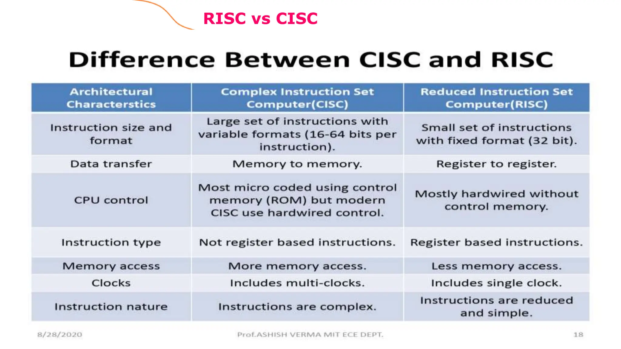
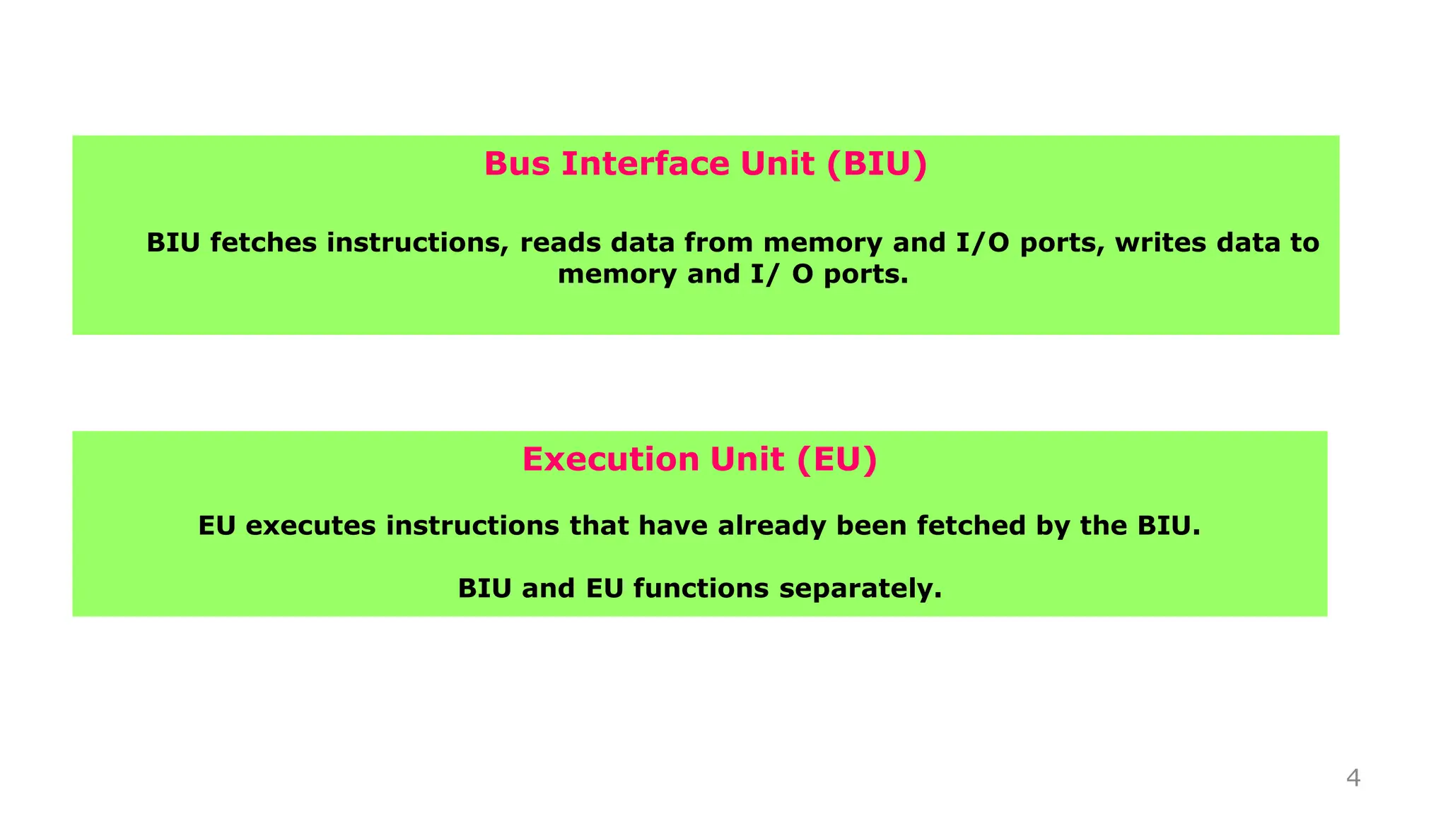
The document discusses the differences between RISC and CISC architectures. It then provides details about the 8086 microprocessor architecture, including its bus interface unit (BIU) and execution unit (EU). It describes the 8086's registers including the accumulator, base, counter, and flag registers. It also covers the various addressing modes supported by the 8086 like immediate, direct, register, register indirect, indexed, register relative, base plus index, and base relative plus index addressing.
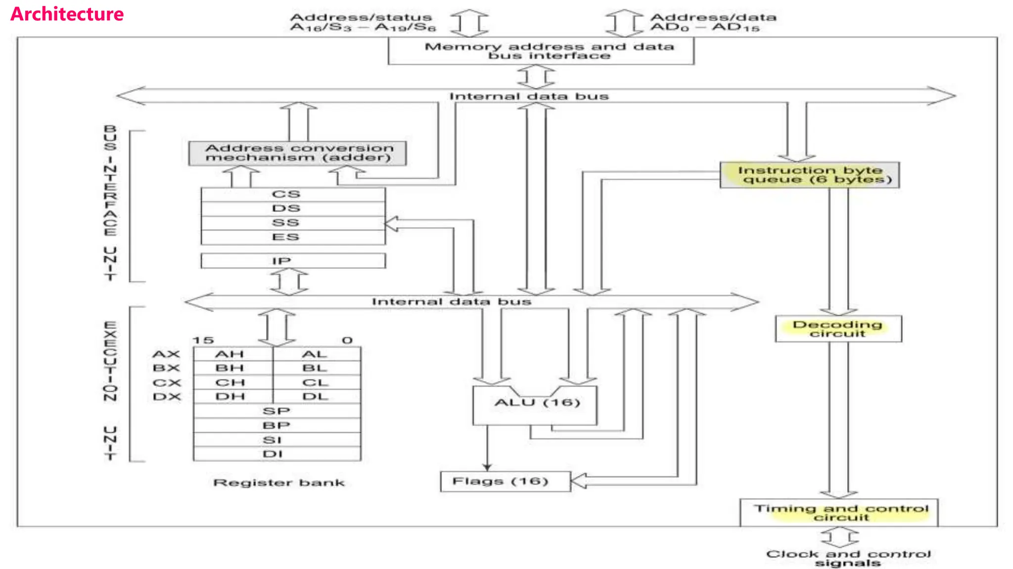
![Architecture
8086 Microprocessor
8
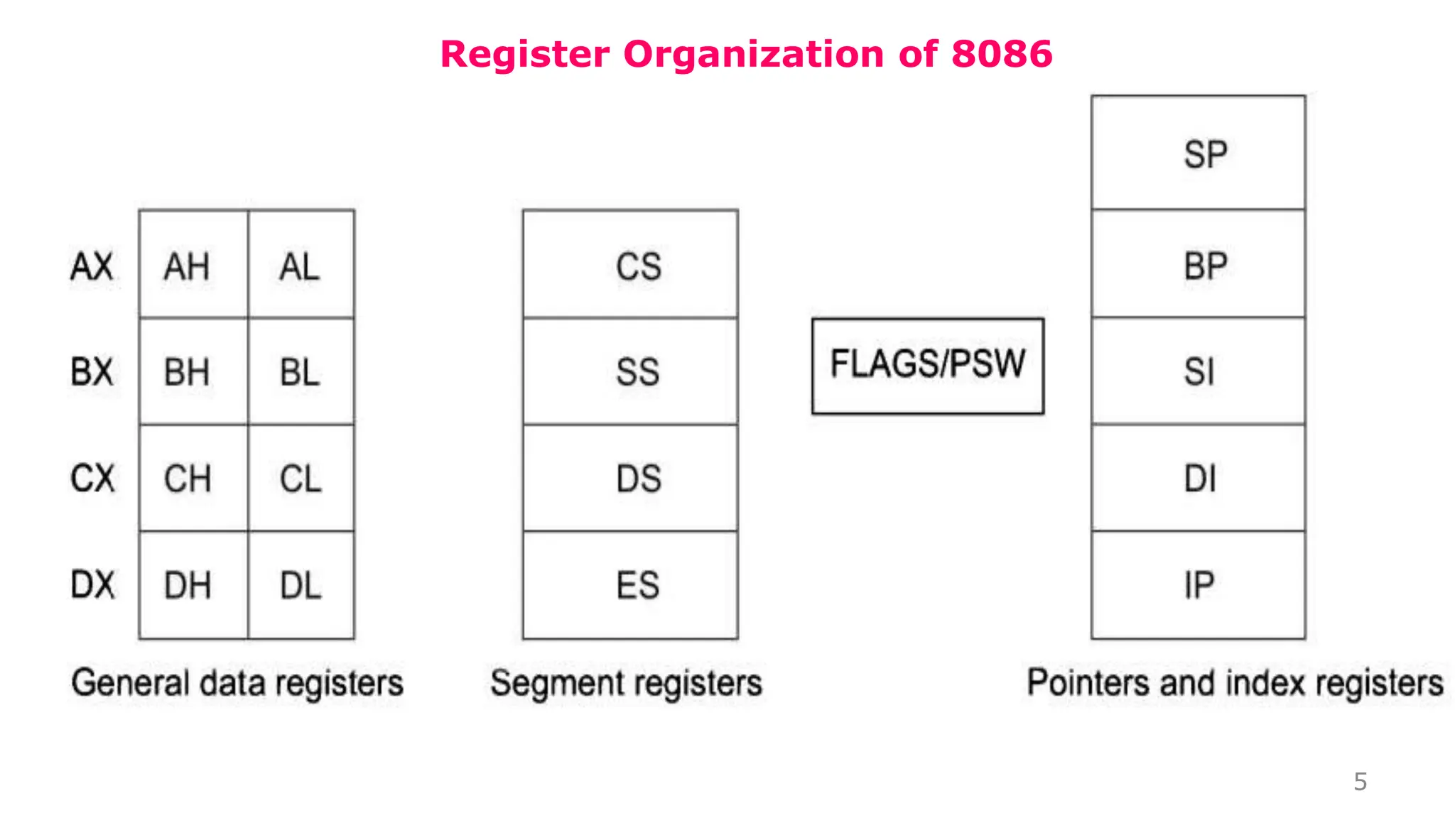
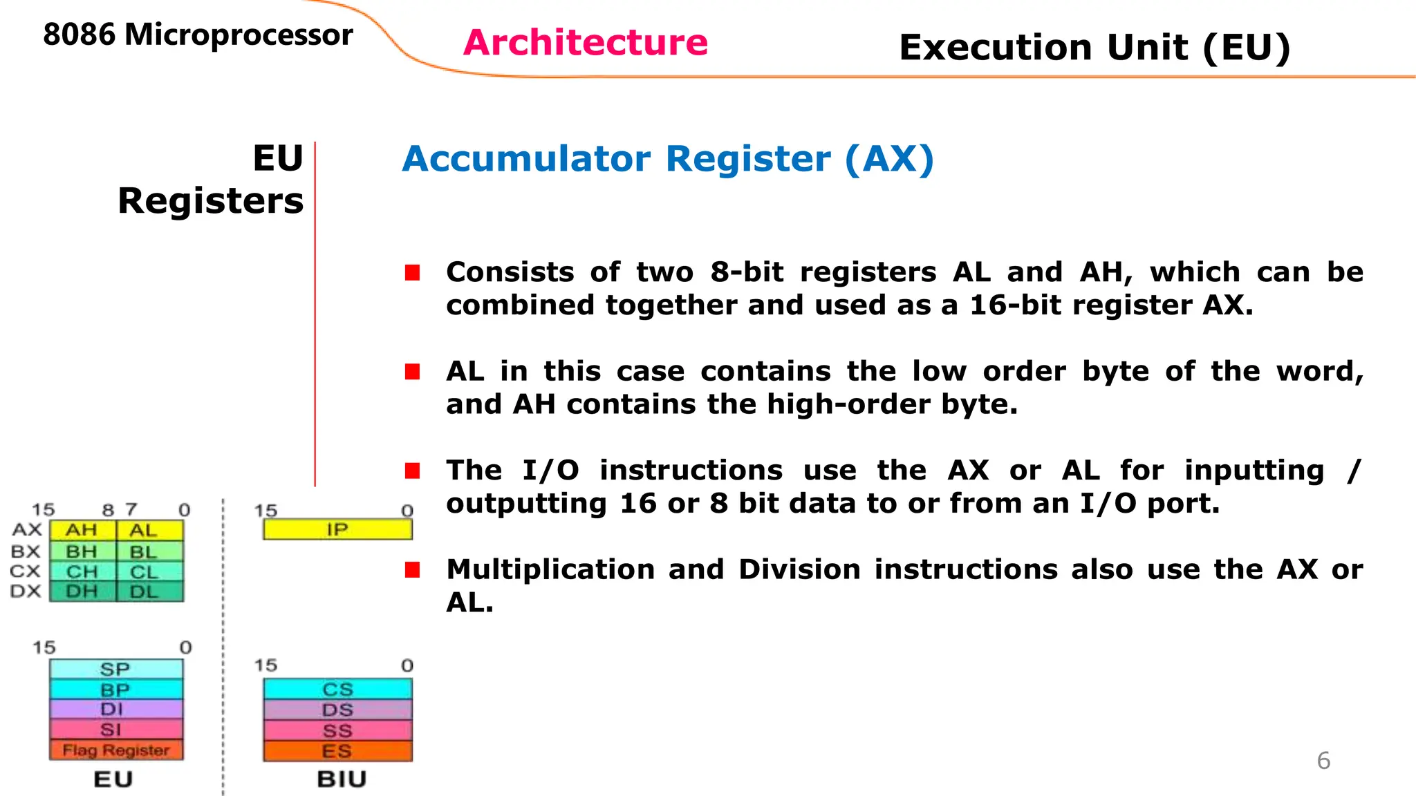
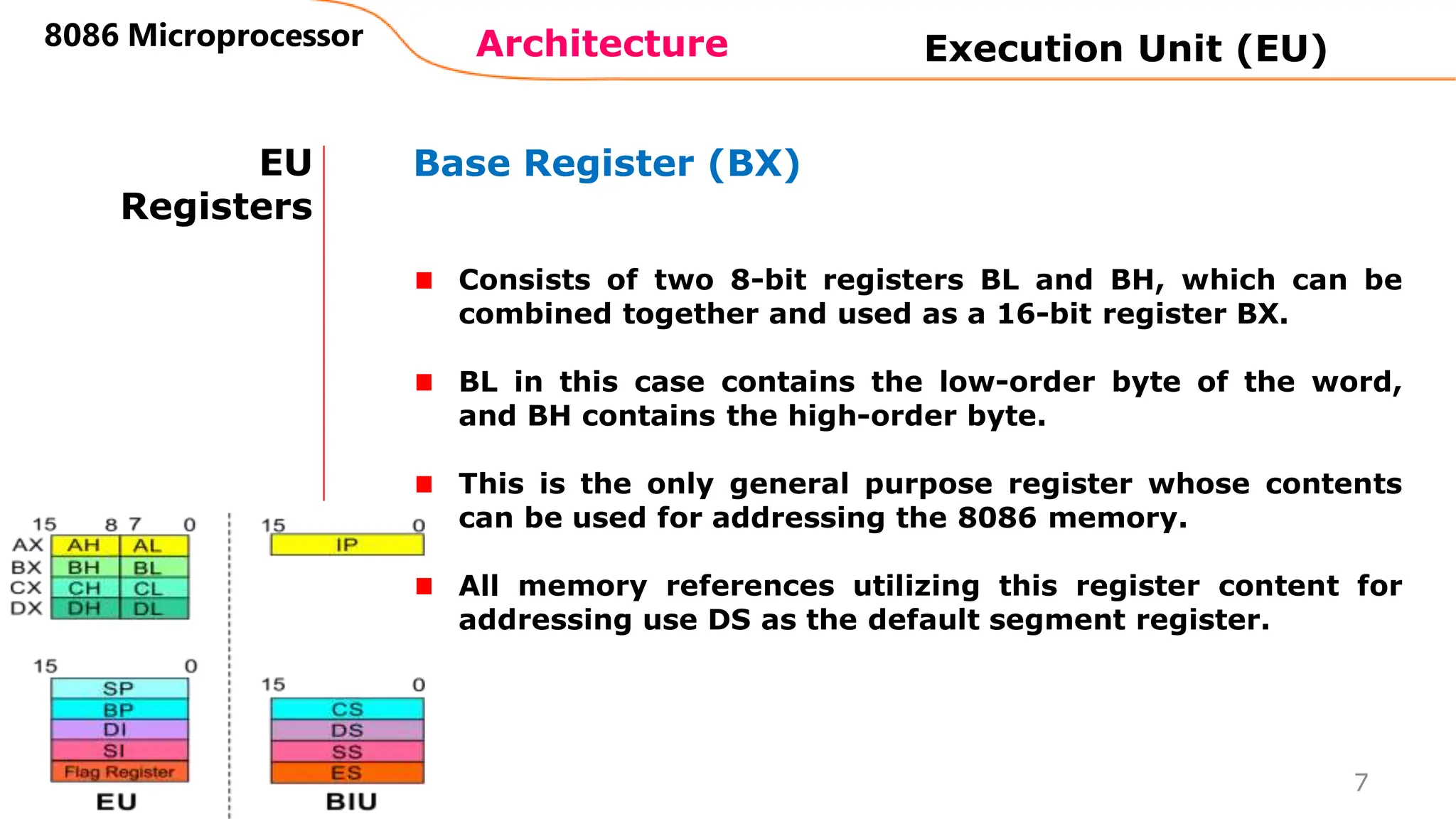
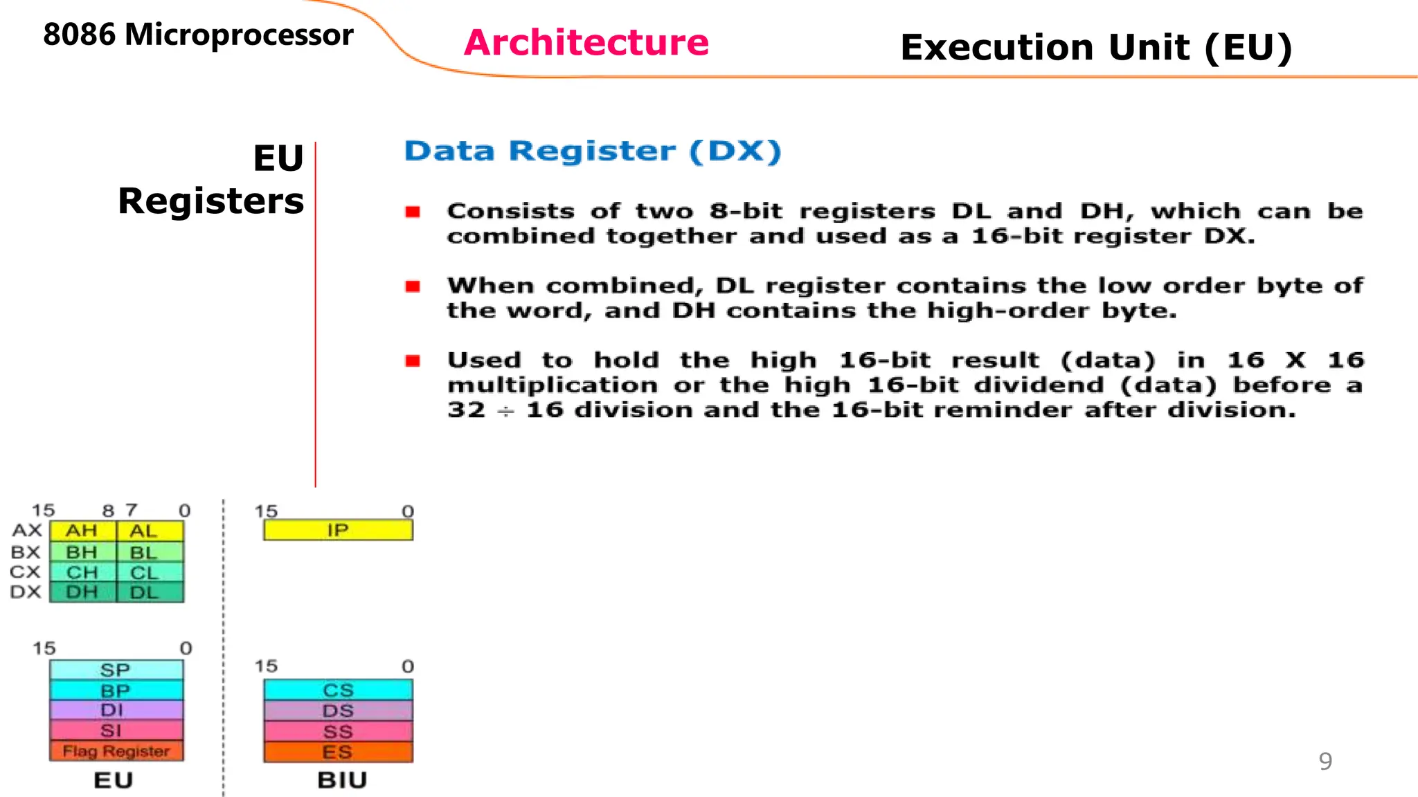
EU
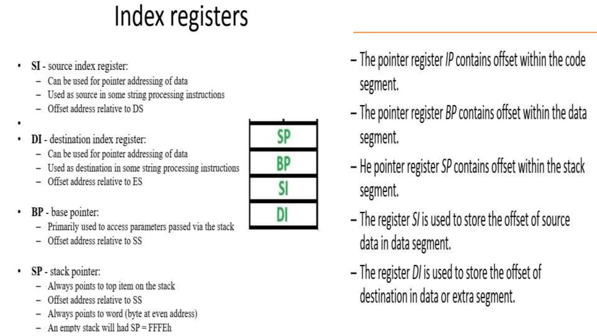
Registers
Counter Register (CX)
Consists of two 8-bit registers CL and CH, which can be
combined together and used as a 16-bit register CX.
When combined, CL register contains the low order byte of
the word, and CH contains the high-order byte.
Instructions such as SHIFT, ROTATE and LOOP use the
contents of CX as a counter.
Execution Unit (EU)
Example:
The instruction LOOP START automatically decrements
CX by 1 without affecting flags and will check if [CX] =
0.
If it is zero, 8086 executes the next instruction;
otherwise the 8086 branches to the label START.](https://image.slidesharecdn.com/8086registerorganization2-240319070828-a1dcf881/75/8086-Register-organization-and-Architecture-details-8-2048.jpg)


![2: Direct addressing mode
• In this type of addressing mode a 16-
bit memory address is directly specified
in the instruction as a part of it.
MOV AX,[5000H]
AX
Memory
5000
5001
5002
22
33
22
33](https://image.slidesharecdn.com/8086registerorganization2-240319070828-a1dcf881/75/8086-Register-organization-and-Architecture-details-17-2048.jpg)
![4: Register Indirect addressing
mode
• The address of the memory location which contains data or
operand is determined in a indirect way, using the offset
register.
MOV AX,[BX]
Memory
5000
5001
5002
22
50 00
AX
BX
33
22
33](https://image.slidesharecdn.com/8086registerorganization2-240319070828-a1dcf881/75/8086-Register-organization-and-Architecture-details-19-2048.jpg)
![Reflection Spot
Q) Which addressing does instruction above belong,
and why?
MOV [7000H],CX](https://image.slidesharecdn.com/8086registerorganization2-240319070828-a1dcf881/75/8086-Register-organization-and-Architecture-details-20-2048.jpg)
![Reflection Spot
Q) Which addressing does instruction above
belonging and why?
MOV [7000H],CX
Memory
7000
7001
7002
22
CX
33
Ans) Direct addressing mode
43 56
43 56](https://image.slidesharecdn.com/8086registerorganization2-240319070828-a1dcf881/75/8086-Register-organization-and-Architecture-details-21-2048.jpg)
![5: Indexed addressing mode
• In this addressing mode, offset of the operand is stored in
one of the index registers. DS is the default segment for
index register SI and DI.
MOV AX,[SI]
Memory
5000
5001
5002
22
50 00
AX
SI
33
22
33](https://image.slidesharecdn.com/8086registerorganization2-240319070828-a1dcf881/75/8086-Register-organization-and-Architecture-details-22-2048.jpg)
![6: Register relative addressing mode
• In this mode, the data is available at an effective address
formed by adding an 8-bit or 16-bit displacement with the
content of any one of the registers BX, BP, SI and DI in the
default (either DS or ES) segment.
MOV AX, 50H[BX]
Memory
5051
5052
5053
44
50 00
AX
BX
33
Offset
+ 50H = 5050H
Final
Index
Address
44
33](https://image.slidesharecdn.com/8086registerorganization2-240319070828-a1dcf881/75/8086-Register-organization-and-Architecture-details-23-2048.jpg)
![7: Base plus index addressing mode
• In this mode the effective address is formed by adding
content of a base register (any one of BX or BP) to the
content of an index register (SI or DI). Default segment
register DS.
MOV AX, [BX] [SI]
3000
3001
3002
10 00
AX
BX
= 3000H
Final
Index
Address
20 00
SI
+
12
34
12
34](https://image.slidesharecdn.com/8086registerorganization2-240319070828-a1dcf881/75/8086-Register-organization-and-Architecture-details-24-2048.jpg)
![8: Base relative plus index addressing mode
• In the effective address is formed by adding an 8 or 16-bit
displacement with sum of contents of any one of the base
registers (BX or BP) and any one of the index registers, in a
default segment.
MOV AX,50H[BX][SI]
3050
3051
3052
10 00
AX
BX
= 3050H
Final
Index
Address
20 00
SI
12
50H +
34
12
34](https://image.slidesharecdn.com/8086registerorganization2-240319070828-a1dcf881/75/8086-Register-organization-and-Architecture-details-25-2048.jpg)


![Vibe Coding vs. Spec-Driven Development [Free Meetup]](https://cdn.slidesharecdn.com/ss_thumbnails/vibecodingvsspecdrivendevelopment-251209105622-43f455e7-thumbnail.jpg?width=640&height=640&fit=bounds)


