This document is a revision of the IEEE 802.1D standard for local and metropolitan area network bridges. It incorporates amendments from IEEE 802.1t and 802.1w, and makes further corrections and improvements. The standard defines the architecture for interconnecting IEEE 802 local area networks below the MAC service boundary using transparent bridges. It specifies the operation of MAC bridges to allow communication between end stations on separate LANs as if they were on the same LAN.


![Copyright © 2004 IEEE. All rights reserved. iii
Introduction
The MAC Bridge standardization activities that resulted in the development of IEEE Std 802.1D-1990
(subsequently republished as IEEE Std 802.1D, 1993 Edition [ISO/IEC 10038:1993] and IEEE Std 802.1D,
1998 Edition [ISO/IEC 15802-3: 1998]) specified an architecture and protocol for the interconnection of
IEEE 802 LANs below the MAC Service boundary.
The 2004 revision of this standard incorporates two amendments into the 1998 Edition:
a) IEEE Std 802.1t-2001, technical and editorial corrections to the 1998 Edition; and
b) IEEE Std 802.1w-2001, Rapid Reconfiguration, which specified the Rapid Spanning Tree Algorithm
and Protocol (RSTP).
In addition, this revision includes further technical and editorial corrections, and removes the original
Spanning Tree Protocol (STP) as a conformance option.
Relationship between IEEE Std 802.1D and IEEE Std 802.1Q
Another IEEE standard, IEEE Std 802.1Q™-2003, extends the concepts of MAC Bridging and filtering
services to support the definition and management of Virtual LANs (VLANs).
The capabilities defined in IEEE Std 802.1Q-2003 include the definition of a VLAN frame format that is
able to carry VLAN identification and user priority information over LAN technologies, such as CSMA/CD,
that have no inherent capability to signal priority information. This information is carried in an additional
header field, known as the Tag Header, which is inserted immediately following the Destination MAC
Address, and Source MAC Address (and Routing Information field, if present) of the original frame. IEEE
Std 802.1Q-2003 extends the priority handling aspects of this standard to make use of the ability of the
VLAN frame format to carry user priority information end to end across any set of concatenated underlying
MACs.
The VLAN Bridging specification contained in IEEE Std 802.1Q-2003 is independent of this standard, in
the sense that IEEE Std 802.1Q-2003 contains its own statement of the conformance requirements for
VLAN Bridges. However, IEEE Std 802.1Q-2003 makes use of many of the elements of the specification
contained in this standard, in particular
a) The Bridge architecture
b) The Internal Sublayer Service, and the specification of its provision by IEEE 802 LAN MACs
c) The major features of the operation of the forwarding process
d) The Rapid Spanning Tree Protocol
e) The Generic Attribute Registration Protocol (GARP)
f) The GARP Multicast Registration Protocol (GMRP)
Since the original Spanning Tree Protocol (STP) has been removed from the 2004 revision of IEEE Std
802.1D, an implementation of RSTP is required for any claim of conformance for an implementation of
IEEE Std 802.1Q-2003 that refers to the current revision of IEEE Std 802.1D unless that implementation
includes the Multiple Spanning Tree Protocol (MSTP) specified in IEEE Std 802.1Q-2003. MSTP is based
on RSTP, extended to provide support for multiple spanning trees.
[This introduction is not part of IEEE Std 802.1D-2004, IEEE Standard for Local and
Metropolitan Area Networks: Media Access Control (MAC) Bridges.]](https://image.slidesharecdn.com/802-150416093300-conversion-gate02/85/802-1-d-2004-5-320.jpg)


![MEDIA ACCESS CONTROL (MAC) BRIDGES IEEE
Std 802.1D-2004
Copyright © 2004 IEEE. All rights reserved. 3
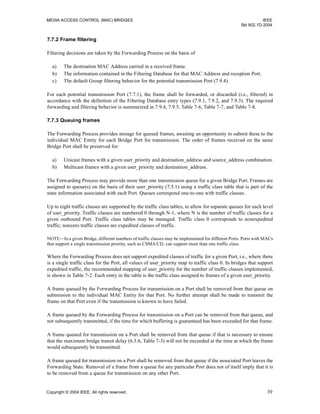
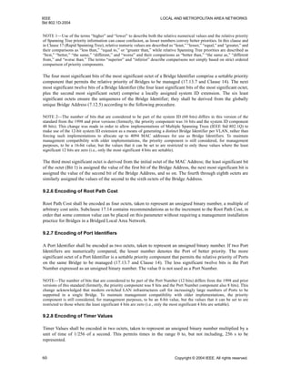
2. References
The following standards contain provisions that, through reference in this text, constitute provisions of this
standard. At the time of publication, the editions indicated were valid. All standards are subject to revision,
and parties to agreements based on this standard are encouraged to investigate the possibility of applying the
most recent editions of the standards indicated below. Members of ISO and IEC maintain registers of
currently valid International Standards.
ANSI X3.159-1989, American National Standards for Information Systems—Programming Language—C.2
IEEE Std 802®-2001, IEEE Standard for Local and Metropolitan Area Networks: Overview and
Architecture.3
IEEE Std 802.1H™
, 1997 Edition [ISO/IEC 11802-5: 1997], Information technology—Telecommunications
and information exchange between systems—Local and metropolitan area networks—Technical reports and
guidelines—Part 5: Media Access Control (MAC) Bridging of Ethernet V2.0 in Local Area Networks.4
IEEE Std 802.1Q™-2003, IEEE Standards for Local and Metropolitan Area Networks: Virtual Bridged Local
Area Networks.
IEEE Std 802.1X™-2001, IEEE Standards for Local and Metropolitan Area Networks—Port Based Network
Access Control.
IEEE Std 802.2™
, 1998 Edition [ISO/IEC 8802-2: 1998], Information technology—Telecommunications
and information exchange between systems—Local and metropolitan area networks—Specific
requirements—Part 2: Logical link control.5
IEEE Std 802.3™
-2002, IEEE Standard for Local and Metropolitan Area Networks, Supplement to Carrier
Sense Multiple Access with Collision Detection (CSMA/CD) Access Method and Physical Layer
Specifications: Aggregation of Multiple Link Segments.
IEEE Std 802.5, 1998 Edition [ISO/IEC 8802-5: 1998], Information technology—Telecommunications and
information exchange between systems—Local and metropolitan area networks—Specific requirements—
Part 5: Token ring access method and physical layer specifications.
IEEE Std 802.11, 1999 Edition [ISO/IEC 8802-11: 1999], Information technology—Telecommunications
and information exchange between systems—Local and metropolitan area networks—Specific
requirements—Part 11: Wireless LAN Medium Access Control (MAC) and Physical Layer (PHY)
specifications.
IETF RFC 2236, Fenner, Internet Group Management Protocol (IGMP), Version 2, November 1975.6
IETF RFC 1493, Decker, Langille, Rijsinghani and McCloughrie, Definitions of Managed Objects for
Bridges, July 1993.
2
ANSI publications are available from the Sales Department, American National Standards Institute, 11 West 42nd Street, 13th Floor,
New York, NY 10036, USA.
3
IEEE publications are available from the Institute of Electrical and Electronics Engineers, 445 Hoes Lane, P.O. Box 1331, Piscataway,
NJ 08855-1331, USA. IEEE publications can be ordered on-line from the IEEE Standards Website: http://www.standards.ieee.org.
4
The IEEE standards or products referred to in this clause are trademarks of the Institute of Electrical and Electronics Engineers, Inc.
5
ISO [IEEE] and ISO/IEC [IEEE] documents are available from ISO Central Secretariat, 1 rue de Varembé, Case Postale 56, CH-1211,
Genève 20, Switzerland/Suisse; and from the Institute of Electrical and Electronics Engineers, 445 Hoes Lane, P.O. Box 1331,
Piscataway, NJ 08855-1331, USA. ISO [IEEE] and ISO/IEC [IEEE] documents can be ordered on-line from the IEEE Standards
Website: http://www.standards.ieee.org.
6
Internet RFCs are available from the Internet Engineering Task Force website at http://www.ietf.org/rfc.html.](https://image.slidesharecdn.com/802-150416093300-conversion-gate02/85/802-1-d-2004-15-320.jpg)


![IEEE LOCAL AND METROPOLITAN AREA NETWORKS
Std 802.1D-2004
20 Copyright © 2004 IEEE. All rights reserved.
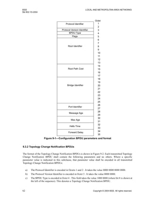
NOTE 1—Since the PAD field, if present, contributes to the FCS, this parameter needs to include at least the
contribution of the PAD field to the FCS in order for the original FCS to be preserved. [See Annex F (informative).]
No special action, above that specified for the support of use of the MAC Service by LLC, is required for the
support of the MAC Internal Sublayer Service by the CSMA/CD access method.
NOTE 2—The support by IEEE Std 802.3 is described only in terms of the operation of a Bridge when relaying frames
that result from the use of LLC services over an IEEE 802.3 MAC. IEEE Std 802.1H defines the recommended practice
for bridging Ethernet V2.0 frames.
The values of the MAC_Enabled and MAC_Operational parameters are determined as follows:
a) For a MAC entity that contains a Link Aggregation sublayer, the value of MAC_Enabled is directly
determined by the value of the aAggAdminState attribute (30.7.1.13 in IEEE Std 802.3-2002), and
the value of MAC_Operational is directly determined by the value of the aAggOperState attribute
(30.7.1.13 in IEEE Std 802.3).
b) Otherwise, for IEEE 802.3 MAC entities that support the MAU managed Object Class
(30.5.1 in IEEE Std 802.3):
1) The value of MAC_Enabled is TRUE.
2) The value of MAC_Operational is TRUE if the attribute aMediaAvailable carries the value
available.
3) The value of MAC_Operational is FALSE if the attribute aMediaAvailable carries any value
other than available.
c) Otherwise:
1) The value of MAC_Enabled is TRUE.
2) The value of MAC_Operational is TRUE.
From the point of view of determining the value of operPointToPointMAC (6.4.3), the MAC is considered to
be connected to a point-to-point LAN if any of the following conditions are true:
a) The MAC entity concerned contains a Link Aggregation sublayer, and the set of physical MACs
associated with the Aggregator are all aggregatable; or
b) The MAC entity concerned supports auto negotiation (Clause 28 of IEEE Std 802.3), and the auto
negotiation function has determined that the LAN is to be operated in full duplex mode; or
c) The MAC entity has been configured by management means for full duplex operation.
Otherwise, the MAC is considered to be connected to a LAN that is not point-to-point.
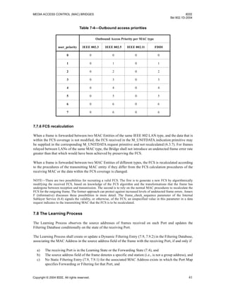
6.5.2 Support by IEEE Std 802.5 (token-passing ring)
The token-passing ring access method is specified in IEEE Std 802.5. Clause 3 of that standard specifies
formats and facilities, and Clause 4 specifies token-passing ring protocols.
On receipt of an M_UNITDATA.request primitive the local MAC Entity composes a frame using the
parameters supplied as specified below, appending the frame control, destination address, source address,
and FCS fields to the user data, and enqueuing the frame for transmission. On transmission, the starting
delimiter, access control field, ending delimiter, and frame status fields are added.
On receipt of a valid MAC frame (IEEE Std 802.5, 4.1.4) that was not transmitted by the Bridge Port’s local
MAC Entity, with the Routing Information Indicator bit (which occupies the same position in the source
address field as does the Group Address bit in the destination address field) set to zero, an
M_UNITDATA.indication primitive is generated, with parameters derived from the frame fields as specified
in the paragraphs that follow.](https://image.slidesharecdn.com/802-150416093300-conversion-gate02/85/802-1-d-2004-32-320.jpg)


![MEDIA ACCESS CONTROL (MAC) BRIDGES IEEE
Std 802.1D-2004
Copyright © 2004 IEEE. All rights reserved. 25
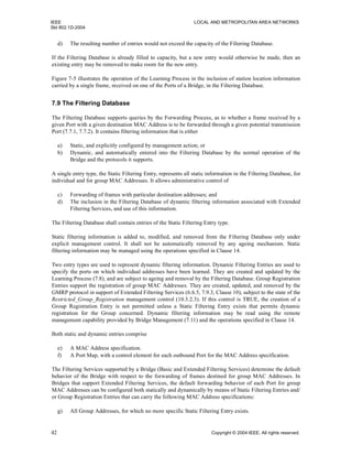
a) Network management and administration, for the purposes of applying administrative control.
Interactions between administrators of the network and the filtering service provider may be
achieved by local means or by means of explicit management mechanisms.
b) End stations, for the purposes of controlling the destination addresses that they will receive.
Interactions between end stations and the filtering service provider may be implicit, as is the case
with the Learning Process (7.8), or by explicit use of filtering service primitives.
6.6.4 Basis of service
All filtering services in Bridged Local Area Networks rely on the establishment of filtering rules, and
subsequent filtering decisions, that are based on the value(s) contained in the Source or Destination MAC
Address fields in MAC frames.
NOTE—The filtering services defined by this standard use source address learning and destination address filtering.
6.6.5 Categories of service
Filtering services in Bridged Local Area Networks fall into the following categories:
a) Basic Filtering Services. These services are supported by the Forwarding Process (7.7) and by Static
Filtering Entries (7.9.1) and Dynamic Filtering Entries (7.9.2) in the Filtering Database. The
information contained in the Dynamic Filtering Entries is maintained through the operation of the
Learning Process (7.8).
b) Extended Filtering Services. These services are supported by the Forwarding Process (7.7), and the
Static Filtering Entries (7.9.1) and Group Registration Entries (7.9.3) in the Filtering Database. The
information contained in the Group Registration Entries is maintained through the operation of
GMRP (10). The categories of Extended Filtering Service are as follows:
1) Support of dynamic Group forwarding and filtering behavior.
2) The ability for static filtering information for individual MAC Addresses to specify a subset of
Ports for which forwarding or filtering decisions are taken on the basis of dynamic filtering
information.
NOTE—Basic Filtering Services as defined in this standard correspond exactly to the filtering capabilities provided by
the MAC Bridges standard in IEEE Std 802.1D, 1993 Edition [ISO/IEC 10038: 1993].
All Bridges shall support Basic Filtering Services and may support either or both categories of Extended
Filtering Services.
6.6.6 Service configuration
In the absence of explicit information in the Filtering Database, the behavior of the Forwarding Process with
respect to the forwarding or filtering of frames destined for group MAC Addresses depends upon the
categories of service supported by the Bridge.
Basic Filtering Services support the filtering behavior required for regions of a Bridged Local Area Network
in which potential recipients of multicast frames exist, but where either the recipients or the Bridges are
either unable to support the dynamic configuration of filtering information for those group MAC Addresses,
or the recipients have a requirement to receive all traffic destined for group MAC Addresses.
Extended Filtering Services support the filtering behavior required for regions of a network in which
potential recipients of multicast frames exist, and where both the potential recipients of frames and the
Bridges are able to support dynamic configuration of filtering information for group MAC Addresses. In
order to integrate this extended filtering behavior with the needs of regions of the network that support only
Basic Filtering Services, Bridges that support Extended Filtering Services can be statically and dynamically](https://image.slidesharecdn.com/802-150416093300-conversion-gate02/85/802-1-d-2004-37-320.jpg)


![MEDIA ACCESS CONTROL (MAC) BRIDGES IEEE
Std 802.1D-2004
Copyright © 2004 IEEE. All rights reserved. 35
7.4 Port States and the active topology
Each Bridge Port has an operational Port State that governs whether or not it forwards MAC frames and
whether or not it learns from their source addresses.
The active topology of a Bridged Local Area Network at any time is the set of communication paths formed
by interconnecting the LANs and Bridges by the forwarding Ports. The function of the distributed Spanning
Tree algorithm and the protocol (Clause 17) that operates that algorithm is to assign Port States to construct
an active topology that is simply connected relative to the forwarding of frames between any given pair of
MAC Addresses used to address end stations on the LANs. The forwarding and learning performed by each
Bridge Port is dynamically managed to prevent temporary loops and reduce excessive traffic in the network
while minimizing denial of service following any change in the physical topology of the network.
Any port that is not enabled, [i.e., has MAC_Operational (6.4.2) False or has been excluded from the active
topology by management setting of the Administrative Bridge Port State to Disabled (14.8.2.2)] or has been
dynamically excluded from forwarding and learning from MAC frames, is assigned the Port State
Discarding. Any Port that has learning enabled but forwarding disabled has the Port State Learning, and a
Port that both learns and forwards frames has the Port State Forwarding.
NOTE—The current IETF Bridge MIB (IETF RFC 1493) uses disabled, blocking, listening, learning, forwarding, and
broken dot1dStpPortStates. The learning and forwarding states correspond exactly to the Learning and Forwarding Port
States specified in this standard. Disabled, blocking, listening, and broken all correspond to the Discarding Port State —
while those dot1dStpPortStates serve to distinguish reasons for discarding frames the operation of the Forwarding and
Learning processes is the same for all of them. The dot1dStpPortState broken represents the failure or unavailability of
the port’s MAC as indicated by MAC_Operational FALSE; disabled represents exclusion of the port from the active
topology by management setting of the Administrative Port State to Disabled; blocking represents exclusion of the port
from the active topology by the spanning tree algorithm [computing an Alternate or Backup Port Role (17.7)]; listening
represents a port that the spanning tree algorithm has selected to be part of the active topology (computing a Root Port or
Designated Port role) but is temporarily discarding frames to guard against loops or incorrect learning.
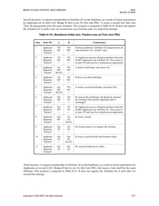
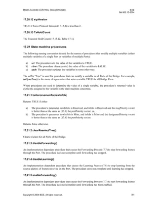
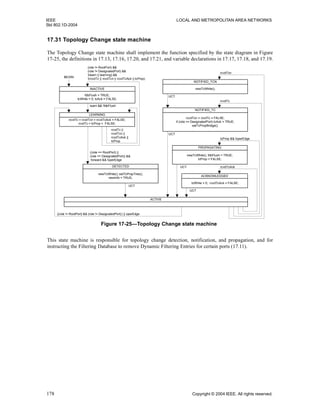
Figure 7-6 illustrates the operation of the Spanning Tree Protocol Entity, which operates the Spanning Tree
Algorithm and its related protocols, and its modification of Port state information as part of determining the
active topology of the Bridged Local Area Network.
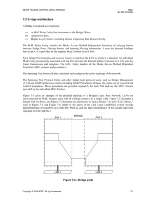
Figure 7-4 illustrates the Forwarding Process’s use of Port state information: first, for a Port receiving a
frame, in order to determine whether the received frame is to be relayed through any other Ports; and second,
for another Port in order to determine whether the relayed frame is to be forwarded through that particular
Port.
Figure 7-5 illustrates the use of the Port state information for a Port receiving a frame, by the Learning
Process, in order to determine whether the station location information is to be incorporated in the Filtering
Database.
7.5 Frame reception
The individual MAC Entity of each Bridge Port examines all frames transmitted on the attached LAN.
All error-free received frames give rise to M_UNITDATA indications that are handled as follows.
NOTE—A frame that is in error, as defined by the relevant MAC specification, is discarded by the MAC Entity without
giving rise to any M_UNITDATA indication (see 6.4).
Frames with an M_UNITDATA.indication frame_type of user_data_frame (6.4), shall be submitted to the
Learning and Forwarding Processes. Frames with other values of frame_type shall not be submitted to the
Forwarding Process. They may be submitted to the Learning Process.](https://image.slidesharecdn.com/802-150416093300-conversion-gate02/85/802-1-d-2004-47-320.jpg)


![MEDIA ACCESS CONTROL (MAC) BRIDGES IEEE
Std 802.1D-2004
Copyright © 2004 IEEE. All rights reserved. 43
h) All Unregistered Group Addresses (i.e., all group MAC Addresses for which no Group Registration
Entry exists), for which no more specific Static Filtering Entry exists.
NOTE—The All Group Addresses specification [item g)], when used in a Static Filtering Entry with an appropriate
control specification, provides the ability to configure a Bridge that supports Extended Filtering Services to behave as a
Bridge that supports only Basic Filtering Services on some or all of its Ports. This might be done for the following
reasons:
— The Ports serve “legacy” devices that wish to receive multicast traffic, but are unable to register Group membership.
— The Ports serve devices that need to receive all multicast traffic, such as routers or diagnostic devices.
The Filtering Database shall support the creation, updating, and removal of Dynamic Filtering Entries by the
Learning Process (7.8). In Bridges that support Extended Filtering Services, the Filtering Database shall
support the creation, updating, and removal of Group Registration Entries by GMRP (Clause 10).
Figure 7-4 illustrates the use of the Filtering Database by the Forwarding Process in a single instance of
frame relay between the Ports of a Bridge with two Ports.
Figure 7-5 illustrates the creation or update of a dynamic entry in the Filtering Database by the Learning
Process.
Figure 7-6 illustrates the operation of the Spanning Tree Protocol Entity (7.10), and its notification of the
Filtering Database of changes in active topology signaled by a spanning tree protocol.
7.9.1 Static Filtering Entries
A Static Filtering Entry specifies
a) A MAC Address specification, comprising
1) An Individual MAC Address; or
2) A Group MAC Address; or
3) All Group Addresses, for which no more specific Static Filtering Entry exists; or
4) All Unregistered Group Addresses, for which no more specific Static Filtering Entry exists.
b) A Port Map, containing a control element for each outbound Port, specifying that a frame with a
destination MAC Address that meets this specification is to be
1) Forwarded, independently of any dynamic filtering information held by the Filtering Database;
or
2) Filtered, independently of any dynamic filtering information; or
3) Forwarded or filtered on the basis of dynamic filtering information, or on the basis of the
default Group filtering behavior for the outbound Port (7.9.4) if no dynamic filtering
information is present specifically for the MAC Address.
All Bridges shall have the capability to support the first two values for the MAC Address specification, and
the first two values for each control element for all Static Filtering Entries [i.e., shall have the capability to
support items a1), a2), b1), and b2) above].
A Bridge that supports Extended Filtering Services shall have the capability to support all four values for the
MAC Address specification and all three control element values for Static Filtering Entries that specify
group MAC Addresses, and may have the capability to support all three control element values for Static
Filtering Entries that specify individual MAC Addresses [i.e., shall have the capability to support items a1)
through a4), and may have the capability to support item b3), in addition to support of items b1) and b2)].
For a given MAC Address specification, a separate Static Filtering Entry with a distinct Port Map may be
created for each inbound Port from which frames are received by the Forwarding Process.](https://image.slidesharecdn.com/802-150416093300-conversion-gate02/85/802-1-d-2004-55-320.jpg)


![IEEE LOCAL AND METROPOLITAN AREA NETWORKS
Std 802.1D-2004
86 Copyright © 2004 IEEE. All rights reserved.
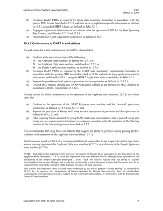
The Applicant is therefore looking after the interests of all would-be Participants. This allows the Registrar
to be very simple.
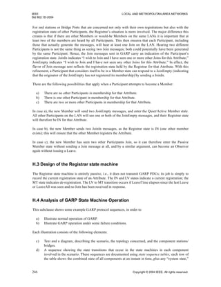
12.6.4 Registrar behavior
The Registrar has a single timer, the leave timer, and the following three states:
a) IN—I have registered the fact that this Attribute value has been declared on this LAN.
b) MT—(Empty) All declarations for this Attribute value on this LAN have been withdrawn.
c) LV—I had registered this Attribute value, but am now timing out the registration (using the leave
timer). If I do not see a declaration for this Attribute before leave timer expires, I will become MT.
The Registrar reacts to received messages as follows:
d) A Join message, either JoinIn or JoinEmpty, causes the Registrar to become IN (I have registered the
Attribute).
e) If the Registrar was IN, then a Leave or LeaveAll causes it to become LV (I am timing out the
registration) and starts the leave timer. Otherwise (LV or MT) there is no effect.
f) An Empty message (someone else has no registration for this Attribute) has no effect [see 12.6.2 a)].
While the Registrar does not send messages, it affects the type of Join message sent by the Applicant. If the
Registrar is IN, a JoinIn is sent; otherwise, a JoinEmpty is sent.
12.6.5 Applicant behavior
Against the background of this simple Registrar, the next consideration is the behavior of the Applicant that
wishes to make a declaration, starting from a point where it has neither seen nor sent any messages.
If no messages were ever lost, the Applicant could either send a Join or receive a JoinIn, and then be content
that all Registrars would have registered its declaration. On the single message loss assumption it needs to
send two Joins, or receive two JoinIns, or send one Join and receive one JoinIn (in either order). This part of
its state could be recorded in a simple counter:
my_membership_msgs = 0, 1, or 2
which is incremented for every Join sent or JoinIn received. If the counter value is 0 or 1 when there is an
opportunity to transmit a PDU, a Join message will be sent and the counter incremented.
NOTE 1—A counter value of greater than 2 is unnecessary for the purposes of successful registration.
NOTE 2—A randomized Join timer is set running to ensure such an opportunity is scheduled. There only needs to be
one Join timer running for the entire Participant, not one per attribute—assuming that messages related to the maximum
number of attributes can be packed into a single PDU.
If a JoinEmpty, Empty, Leave, or LeaveAll message is received, the counter is reset to 0.
When the Applicant leaves the Group, it sends a single Leave message.
12.6.5.1 Anxious Applicants
Expressing protocol behavior in terms of counter and flag variables is not always the best approach if
enabling thorough analysis and maximizing implementation flexibility are primary goals. From this point
on, the values assigned to the join message count are given the following state name prefixes:](https://image.slidesharecdn.com/802-150416093300-conversion-gate02/85/802-1-d-2004-98-320.jpg)


![IEEE LOCAL AND METROPOLITAN AREA NETWORKS
Std 802.1D-2004
90 Copyright © 2004 IEEE. All rights reserved.
transmitPDU! An opportunity to transmit a GARP PDU has occurred. A maximum transmission rate is
imposed of no more than three such transmission opportunities in any period of
1.5*JoinTime seconds.
12.7 State machine descriptions
The following conventions are used in the abbreviations used in this subclause:
rXXX receive PDU XXX
sXXX send PDU XXX
ReqXXX GID service request XXX
IndXXX GID service indication XXX
The following abbreviations are used in the state machine descriptions. For a formal definition of their
meaning, see 12.9:
Initialize state machine (re)initialization event.
rJoinIn receive Join In message
rJoinEmpty receive Join Empty message
rEmpty receive Empty message
rLeaveIn receive Leave In message
rLeaveEmpty receive Leave Empty message
LeaveAll receive or send a LeaveAll message
sJ[E,I] send Join In message if Registrar state = IN; otherwise, send Join Empty message
sJ[I] send Join In message
sE send Empty message
sLE send Leave Empty message
sLeaveAll send Leave All message
ReqJoin GID Service Request to declare an Attribute value
ReqLeave GID Service Request to withdraw an Attribute value declaration
IndJoin Issue GID Service Indication signaling an Attribute value has been registered
IndLeave Issue GID Service Indication signaling an Attribute value has been de-registered
transmitPDU! An opportunity to transmit a GARP PDU has occurred. Such events occur at intervals
randomly chosen in the interval 0 - JoinTime. JoinTime is as defined in
Table 12-10
leavetimer Leave period timer
leavetimer! leavetimer has expired
leavealltimer Leave All period timer.
leavealltimer! leavealltimer has expired.
-x- Inapplicable event/state combination. No action or state transition occurs.
Timers are used in the state machine descriptions in order to cause actions to be taken after defined time
periods have elapsed. The following terminology is used in the state machine descriptions to define timer
states and the actions that can be performed upon them:
a) A timer is said to be running if the most recent action to be performed upon it was a start or a
restart.
b) A running timer is said to have expired when the time period associated with the timer has elapsed
since the most recent start or restart action took place.
c) A timer is said to be stopped if it has expired or if the most recent action to be performed upon it was
a stop action.](https://image.slidesharecdn.com/802-150416093300-conversion-gate02/85/802-1-d-2004-102-320.jpg)
![IEEE LOCAL AND METROPOLITAN AREA NETWORKS
Std 802.1D-2004
92 Copyright © 2004 IEEE. All rights reserved.
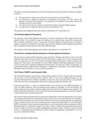
12.7.2 Registrar state machine
A full GARP Participant maintains a single instance of this state machine for each Attribute value that is
currently registered, or that the Registrar state machine is in the process of de-registering.
NOTE—As with the Applicant, state information is conceptually maintained for all possible values of all Attribute types
that are defined for a given Application; however, in real implementations of GARP, it is likely that the range of possible
Attribute values in some Applications will preclude this, and the implementation will limit the state to those Attribute
values in which the Participant has an immediate interest. In the case of simple devices that have no interest in what
other Participants have registered, it may be appropriate for that device to ignore Registrar operation altogether.
The detailed operation of this state machine is described in Table 12-4.
The initial state for the Registrar state machine on (re)initialization is MT.
12.7.3 Leave All state machine
A single Leave All state machine exists for each full GARP Participant. Leave All messages generated by
this state machine also generate LeaveAll events against all the Applicant and Registrar state machines
associated with that Participant and Port; hence, LeaveAll generation is treated by those state machines in
the same way as reception of a LeaveAll message from an external source.
The detailed operation of this state machine is described in Table 12-5.
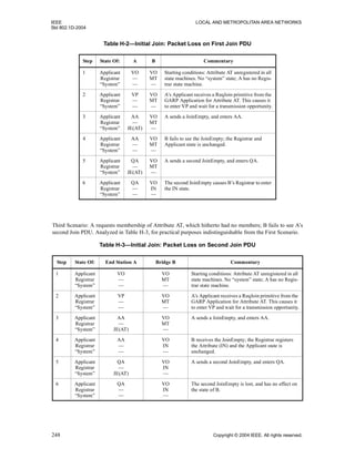
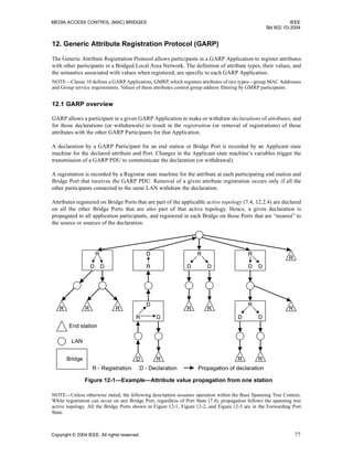
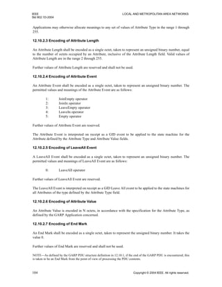
12.7.4 Combined Applicant and Registrar state machine
Table 12-6 shows all the reachable states, with cells containing the joint state names, Applicant.Registrar,
and unreachable states marked ---. The MT and LV Registrar states are grouped together since the only event
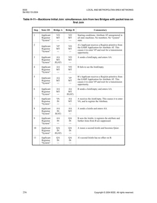
Table 12-3—Applicant state table
STATE
VA AA QA LA VP AP QP VO AO QO LO
EVENT
transmitPDU!
sJ[E,I]
AA
sJ[E,I]
QA
-x-
sLE
VO
sJ[E,I]
AA
sJ[E,I]
QA
-x-
-x- -x- -x-
sE
VO
rJoinIn AA QA QA LA AP QP QP AO QO QO AO
rJoinEmpty VA VA VA VO VP VP VP VO VO VO VO
rEmpty VA VA VA LA VP VP VP VO VO VO VO
rLeaveIn VA VA VP LA VP VP VP LO LO LO VO
rLeaveEmpty VP VP VP VO VP VP VP LO LO LO VO
LeaveAll VP VP VP VO VP VP VP LO LO LO VO
ReqJoin -x- -x- -x- VA -x- -x- -x- VP AP QP VP
ReqLeave LA LA LA -x- VO AO QO -x- -x- -x- -x-
Initialize VO VO VO VO VO VO VO VO VO VO VO](https://image.slidesharecdn.com/802-150416093300-conversion-gate02/85/802-1-d-2004-104-320.jpg)
![MEDIA ACCESS CONTROL (MAC) BRIDGES IEEE
Std 802.1D-2004
Copyright © 2004 IEEE. All rights reserved. 95
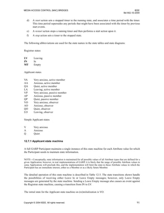
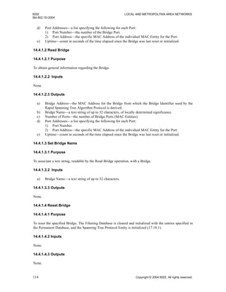
12.7.6 Simple-Applicant Participant
A Simple-Applicant Participant maintains a single instance of the Simple Applicant state machine for each
Attribute value for which the Participant needs to maintain state information.
The detailed operation of this state machine is described in Table 12-9. The state transitions shown handle
the possibilities of receiving either Leave In or Leave Empty messages; however, only Leave Empty
messages are generated by the state machine.
12.8 Administrative controls
Associated with each instance of the Registrar state machines are Registrar Administrative Control
parameters. These parameters allow administrative control to be exercised over the registration state of each
Attribute value, and hence, via the propagation mechanism provided by GIP, allow control to be exercised
over the propagation of declarations.
An overall control parameter for each Applicant state machine, the Applicant Administrative Control,
determines whether or not the Applicant state machine participates in GARP protocol exchanges.
These parameters can be set to the values defined in 12.8.1 and 12.8.2.
12.8.1 Registrar Administrative Control values
a) Normal Registration. The Registrar responds normally to incoming GARP messages.
b) Registration Fixed. The Registrar ignores all GARP messages, and remains in the IN (registered)
state.
c) Registration Forbidden. The Registrar ignores all GARP messages, and remains in the EMPTY
(unregistered) state.
Table 12-8—Applicant Only State Machine
STATE
VA AA QA LA VP AP QP VO AO QO
EVENT
transmitPDU!
sJ[I]
AA
sJ[I]
QA
-x-
sLE
VO
sJ[I]
AA
sJ[I]
QA
-x- -x- -x- -x-
rJoinIn AA QA QA LA AP QP QP AO QO QO
rJoinEmpty VA VA VA VO VP VP VP VO VO VO
rEmpty VA VA VA LA VP VP VP VO VO VO
rLeaveIn VA VA VA LA VP VP VP VO VO VO
rLeaveEmpty VP VP VP VO VP VP VP VO VO VO
LeaveAll VP VP VP VO VP VP VP VO VO VO
ReqJoin -x- -x- -x- VA -x- -x- -x- VP AP QP
ReqLeave LA LA LA -x- VO AO QO -x- -x- -x-
Initialize VO VO VO VO VO VO VO VO VO VO](https://image.slidesharecdn.com/802-150416093300-conversion-gate02/85/802-1-d-2004-107-320.jpg)
![IEEE LOCAL AND METROPOLITAN AREA NETWORKS
Std 802.1D-2004
96 Copyright © 2004 IEEE. All rights reserved.
The default value of this parameter is Normal Registration.
Optionally, an implementation may support the ability to record against each Registrar state machine the
MAC Address of the originator of the GARP PDU that caused the most recent state change for that state
machine.
NOTE—The Registrar Administrative Controls are realized by means of the contents of the Port Map parameters of
static entries in the Filtering Database for all GARP applications. In the case of GMRP, the static entries concerned are
Static Filtering Entries (7.9.1 and 10.3.2.3). The contents of the Port Map parameters in static entries can be modified by
means of the management operations defined in 14.7. In the absence of such control information for a given attribute, the
default value “Normal Registration” is assumed.
12.8.2 Applicant Administrative Control values
a) Normal Participant. The state machine participates normally in GARP protocol exchanges.
b) Non-Participant. The state machine does not send any GARP messages.
The default value of this parameter is Normal Participant.
NOTE—The Applicant Administrative Control parameters can be modified for any GARP application by means of the
management operations defined in 14.9. In the absence of such information for a given attribute, the default value
“Normal Participant” is assumed.
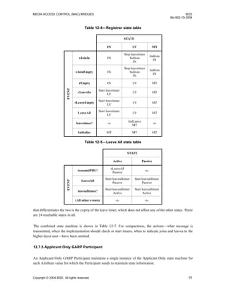
12.9 Procedures
The following subclauses define the protocol actions and procedures that are identified in the description of
the State Machines contained in 12.7.
Table 12-9—Simple Applicant State Machine
STATE
V A Q
EVENT
transmitPDU!
sJ[I]
A
sJ[I]
Q
-x-
rJoinIn A Q Q
rJoinEmpty V V V
rEmpty V V V
rLeaveIn V V V
rLeaveEmpty V V V
LeaveAll V V V
ReqJoin -x- -x- -x-
ReqLeave
sLE
O
sLE
O
sLE
O](https://image.slidesharecdn.com/802-150416093300-conversion-gate02/85/802-1-d-2004-108-320.jpg)


![IEEE LOCAL AND METROPOLITAN AREA NETWORKS
Std 802.1D-2004
100 Copyright © 2004 IEEE. All rights reserved.
For an instance of the LeaveAll state machine, the transmitPDU! event is deemed to have occurred when the
state machine has an opportunity to transmit a LeaveAll message.
12.9.4 Action definitions
Unless stated otherwise in these action definitions, GARP PDU transmission as a result of the operation of a
state machine in a Bridge occurs only through the Port associated with that state machine, and only if that
Port is in the Forwarding state.
12.9.4.1 -x-
No action is taken.
12.9.4.2 sJ[E, I], sJ[I]
A GARP PDU, formatted as defined in 12.10.1, is transmitted. The PDU shall be formatted such that
a) The PDU contains a Message (12.10.1.2) that carries an Attribute Type (12.10.2.2) that specifies the
type associated with the state machine.
b) The Message contains an Attribute (12.10.1.2) that specifies an Attribute Event (12.10.2.4) equal to
JoinIn (if the Registrar is in the IN state, or if no Registrar functionality is implemented) or
JoinEmpty (if the Registrar is in either the LV or the MT state), and an Attribute Value equal to the
value associated with the state machine.
The PDU shall be transmitted using, as the destination MAC Address, the GARP Application address of the
GARP Application associated with the state machine.
12.9.4.3 sE
A GARP PDU, formatted as defined in 12.10.1, is transmitted. The PDU shall be formatted such that
a) The PDU contains a Message (12.10.1.2) that carries an Attribute Type (12.10.2.2) that specifies the
type associated with the state machine.
b) The Message contains an Attribute (12.10.1.2) that specifies an Attribute Event (12.10.2.4) equal to
Empty, and an Attribute Value equal to the value associated with the state machine.
The PDU shall be transmitted using, as the destination MAC Address, the GARP Application address of the
GARP Application associated with the state machine.
12.9.4.4 sLE
A GARP PDU, formatted as defined in 12.10.1, is transmitted. The PDU shall be formatted such that
a) The PDU contains a Message (12.10.1.2) that carries an Attribute Type (12.10.2.2) that specifies the
type associated with the state machine.
b) The Message contains an Attribute (12.10.1.2) that specifies an Attribute Event (12.10.2.4) equal to
LeaveEmpty, and an Attribute Value equal to the value associated with the state machine.
The PDU shall be transmitted using, as the destination MAC Address, the GARP Application address of the
GARP Application associated with the state machine.](https://image.slidesharecdn.com/802-150416093300-conversion-gate02/85/802-1-d-2004-112-320.jpg)


![IEEE LOCAL AND METROPOLITAN AREA NETWORKS
Std 802.1D-2004
146 Copyright © 2004 IEEE. All rights reserved.
To ensure that old information does not endlessly circulate through redundant paths in the network and
prevent propagation of new information, each Configuration Message includes a message age and a
maximum age. The message age is incremented on receipt, and the information discarded if it exceeds the
maximum. Thus the number of Bridges the information can traverse is limited.
The MAC_Operational parameter (6.4.2) for each Bridge Port can signal failure conditions in some MACs.
If it becomes FALSE the Port becomes a Disabled Port and received information is immediately discarded.
If the Bridge has Designated Ports, changed information will be transmitted and propagated. This enables
rapid reassignment of Port Roles that depended on the prior physical topology.
Not all MAC component failure conditions can be detected and signalled by changes in MAC_Operational
status, so received spanning tree information is aged out if not refreshed by the regular reception of
Configuration Messages from the Designated Port.
17.10 Changing Port States
The Port State of each Bridge Port is controlled by the Port Role Transitions state machine (17.29), whose
goal is to maximize connectivity without introducing temporary loops. It attempts to transition Root Ports
and Designated Ports to the Forwarding Port State, and Alternate Ports and Backup Ports to the Discarding
Port State, as rapidly as possible.
Transitions to Discarding can be effected without the risk of data loops. Transitions to Forwarding need to be
consistent with the Port Roles and States of the other Ports in the region of the network bounded by this Port
and by Ports that are not Forwarding or that attach to a LAN with no other attached Bridges.
A Bridge knows that a Port can become Forwarding, following a change in spanning tree information that
causes it to be assigned a Root or Designated Port Role, if:
a) Enough time has elapsed for the information to reach all Bridges in the region, and for contradictory
information to be received from any Bridge in the region, or
b) The Port is now a Root Port, and any Ports on the Bridge that have been Root Port are not and will
not become Forwarding [with the exception of item c) below] until the spanning tree information
reaches all the other Bridges in the network, or
c) The Port is a Designated Port attached, via a LAN, to at most one other Bridge whose Port States are
either consistent with the spanning tree information or Discarding, as are the Port States of the
further Bridges connected through their Forwarding Ports, or
d) The Port is an Edge Port (17.3, 17.19.17).
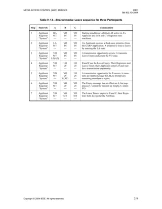
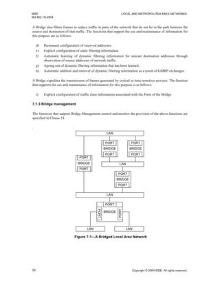
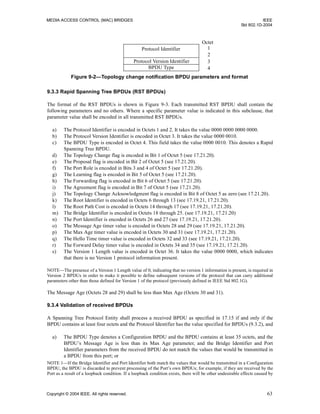
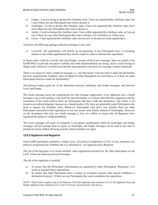
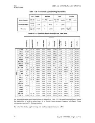
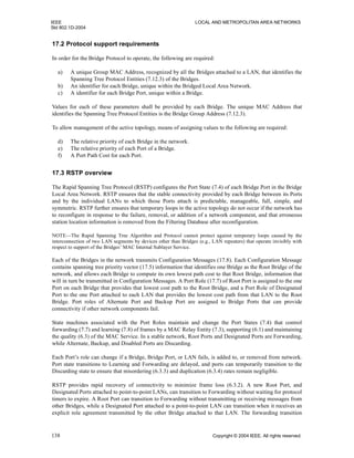
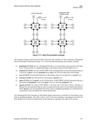
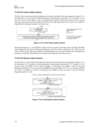
Figure 17-7 illustrates conditions b) and c). As a result of management of the Port priorities of Bridge 222,
an Alternate Port becomes its new Root Port, and the old Root Port an Alternate Port. Assuming that the
initial configuration had been stable for the necessary time, and that the old Root Port’s State is now
Discarding, the new Root Port can be made Forwarding, by applying condition b).
If the Designated Port attached to LAN G is not Forwarding for some reason (a very recent transition from
administratively disabled to enabled, for example), Bridge 111 will exchange messages with Bridge 222 to
satisfy condition c).](https://image.slidesharecdn.com/802-150416093300-conversion-gate02/85/802-1-d-2004-158-320.jpg)


![MEDIA ACCESS CONTROL (MAC) BRIDGES IEEE
Std 802.1D-2004
Copyright © 2004 IEEE. All rights reserved. 151
17.12 RSTP and point-to-point links
The rapid transition of a Designated Port to Forwarding depends on the Port being directly connected to at
most one other Bridge [it is an Edge Port (17.3, 17.19.17), or is attached to a point-to-point LAN, rather than
a shared medium]. The adminPointToPointMAC and operPointToPointMAC parameters (6.4.3) provide
management and signalling of the point-to-point status to RSTP state machines.
A newly selected Root Port can transition to Forwarding rapidly, even if attached to shared media.
17.13 RSTP performance parameters
These parameters are not modified by the operation of RSTP, but are treated as constants by the RSTP state
machines and the associated variables and procedures (17.20, 17.18, 17.19). They may be modified by
management.
The Spanning Tree Protocol Entity shall be reinitialized, as specified by the assertion of BEGIN (17.18.1) in
the state machine specification, if the following parameters are modified:
a) Force Protocol Version (17.13.4)
The spanning tree priority vectors and Port Role assignments for a Bridge shall be recomputed, as specified
by the operation of the Port Role Selection state machine (17.28) by clearing selected (17.19.36) and setting
reselect (17.19.34) for any Port or Ports for which the following parameters are modified:
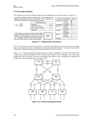
Figure 17-11—Root Port transition—tree partitioning
111, 0
111 1
2
34
111, 10
222
43
2
1
111, 10
333
1 2
3
45
6 111, 10
444
1 2
3
45
6
111, 20
555
1 2
34
111, 20
666
1 2
34
111, 20
777
1 2
34
111, 20
888
1 2
34
C
D E
G HI JK LM N
F
A
B
O
"Main Tree"
"Subtree"](https://image.slidesharecdn.com/802-150416093300-conversion-gate02/85/802-1-d-2004-163-320.jpg)


![IEEE LOCAL AND METROPOLITAN AREA NETWORKS
Std 802.1D-2004
158 Copyright © 2004 IEEE. All rights reserved.
17.17.1 edgeDelayWhile
The Edge Delay timer. The time remaining, in the absence of a received BPDU, before this port is identified
as an operEdgePort.
17.17.2 fdWhile
The Forward Delay timer. Used to delay Port State transitions until other Bridges have received spanning
tree information.
17.17.3 helloWhen
The Hello timer. Used to ensure that at least one BPDU is transmitted by a Designated Port in each
HelloTime period.
17.17.4 mdelayWhile
The Migration Delay timer. Used by the Port Protocol Migration state machine to allow time for another
RSTP Bridge on the same LAN to synchronize its migration state with this Port before the receipt of a
BPDU can cause this Port to change the BPDU types it transmits. Initialized to MigrateTime (17.13.9).
17.17.5 rbWhile
The Recent Backup timer. Maintained at its initial value, twice HelloTime, while the Port is a Backup Port.
17.17.6 rcvdInfoWhile
The Received Info timer. The time remaining before the spanning tree information received by this Port
[portPriority (17.19.21) and portTimes (17.19.22)] is aged out if not refreshed by the receipt of a further
Configuration Message.
17.17.7 rrWhile
The Recent Root timer.
17.17.8 tcWhile
The Topology Change timer. TCN Messages are sent while this timer is running.
17.18 Per-Bridge variables
The variables declared in this subclause are part of the specification of the operation of the RSTP. The
accompanying descriptions of their use are provided to aid in the comprehension of the protocol only, and
are not part of the specification.
17.18.1 BEGIN
A Boolean controlled by the system initialization (17.16). If TRUE causes all state machines, including per
Port state machines, to continuously execute their initial state.](https://image.slidesharecdn.com/802-150416093300-conversion-gate02/85/802-1-d-2004-170-320.jpg)

![MEDIA ACCESS CONTROL (MAC) BRIDGES IEEE
Std 802.1D-2004
Copyright © 2004 IEEE. All rights reserved. 161
17.19.13 mcheck
A boolean. May be set by management to force the Port Protocol Migration state machine to transmit RST
BPDUs for a MigrateTime (17.13.9) period, to test whether all STP Bridges (17.4) on the attached LAN
have been removed and the Port can continue to transmit RSTP BPDUs. Setting mcheck has no effect if
stpVersion (17.20.12) is TRUE, i.e., the Bridge is operating in “STP Compatibility” mode.
17.19.14 msgPriority
The first four components of the message priority vector conveyed in a received BPDU, as defined in 17.6.
17.19.15 msgTimes
The msgTimes variable comprises the timer parameter values (Message Age, Max Age, Forward Delay, and
Hello Time) conveyed in a received BPDU.
17.19.16 newInfo
A boolean. Set if a BPDU is to be transmitted. Reset by the Port Transmit state machine.
17.19.17 operEdge
A boolean. The value of the operEdgePort parameter, as determined by the operation of the Bridge Detection
state machine (17.25).
17.19.18 portEnabled
A boolean. Set if the Bridge’s MAC Relay Entity and Spanning Tree Protocol Entity can use the MAC
Service provided by the Port’s MAC entity to transmit and receive frames to and from the attached LAN,
i.e., portEnabled is TRUE if and only if:
a) MAC_Operational (6.4.2) is TRUE; and
b) Administrative Bridge Port State (14.8.2.2) for the Port is Enabled; and
c) AuthControlledPortStatus is Authorized [if the port is a network access port (IEEE Std 802.1X)].
17.19.19 portId
The Port Identifier. This variable forms the fifth component of the port priority and designated priority
vectors defined in 17.6.
17.19.20 PortPathCost
The Port’s contribution, when it is the Root Port, to the Root Path Cost (17.3.1, 17.5, 17.6) for the Bridge.
17.19.21 portPriority
The first four components of the Port’s port priority vector value, as defined in 17.6.
17.19.22 portTimes
The portTimes variable comprises the Port’s timer parameter values (Message Age, Max Age, Forward
Delay, and Hello Time). These timer values are used in BPDUs transmitted from the Port.](https://image.slidesharecdn.com/802-150416093300-conversion-gate02/85/802-1-d-2004-173-320.jpg)


![IEEE LOCAL AND METROPOLITAN AREA NETWORKS
Std 802.1D-2004
186 Copyright © 2004 IEEE. All rights reserved.
A.4 PICS proforma for IEEE Std 802.1D
A.4.1 Implementation identification
Supplier
Contact point for queries about the PICS
Implementation Name(s) and Version(s)
Other information necessary for full identi-
fication—e.g., name(s) and version(s) of
machines and/or operating system names
NOTE 1—Only the first three items are required for all implementations; other information may be completed as
appropriate in meeting the requirement for full identification.
NOTE 2—The terms Name and Version should be interpreted appropriately to correspond with a supplier’s
terminology (e.g., Type, Series, Model).
A.4.2 Protocol summary, IEEE Std 802.1D
Identification of protocol specification IEEE Std 802.1D, IEEE Standard for Local and Metropolitan Area
Networks: Media Access Control (MAC) Bridges
Identification of amendments and corrigenda
to the PICS proforma that have been com-
pleted as part of the PICS
Amd. : Corr. :
Amd. : Corr. :
Have any Exception items been required?
(See A.3.3: the answer Yes means that the
implementation does not conform to IEEE
Std 802.1D.)
No [ ] Yes [ ]
Date of Statement](https://image.slidesharecdn.com/802-150416093300-conversion-gate02/85/802-1-d-2004-198-320.jpg)
![MEDIA ACCESS CONTROL (MAC) BRIDGES IEEE
Std 802.1D-2004
Copyright © 2004 IEEE. All rights reserved. 187
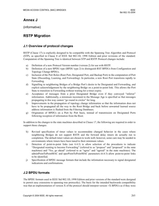
A.5 Major Capabilities
Item Feature Status References Support
MAC Do the implementations of MAC Technologies and sup-
port of the MAC Internal Sublayer Service conform to
MAC standards as specified in 6.4 and 6.5?
(If support of a specific MAC technology is claimed any
PICS Proforma(s) required by the Standard specifying that
technology shall also be completed.)
M 6.4, 6.5.
A.6
Yes [ ]
LLC Is a class of LLC supporting Type 1 operations supported
on all Bridge Ports in conformance with IEEE Std 802.2?
(The PICS Proforma required by IEEE Std 802.2 shall
also be completed.)
M 7.2, 7.3, 7.12.
IEEE Std 802.2
Yes [ ]
RLY Does the implementation relay and filter frames as
specified?
M 7.1, 7.5, 7.6, and
7.7.
A.7
Yes [ ]
BFS Does the implementation maintain the information
required to make frame filtering decisions and support
Basic Filtering Services?
M 7.1, 7.5, 7.8, and
7.9.
A.8
Yes [ ]
ADDR Does the implementation conform to the provisions for
addressing?
M 7.12
A.9
Yes [ ]
RSTP Is the Rapid Spanning Tree Protocol implemented? M 17
A.10
Yes [ ]
BPDU Are transmitted BPDUs encoded and received BPDUs
validated as specified?
M 9, 17.21.19,
17.21.20,
and17.21.21.
A.11
Yes [ ]
IMP Are the required implementation parameters included in
this completed PICS?
M 7.9
A.12
Yes [ ]
PERF Are the required performance parameters included in this
completed PICS?
(Operation of the Bridge within the specified parameters
shall not violate any of the other conformance provisions
of this standard.)
M 16
A.13
Yes [ ]
MGT Is management of the Bridge supported? O 14
A.14
Yes [ ] No [ ]
RMGT Is a remote management protocol supported? MGT:O 5.2
A.15
Yes [ ] No [ ]
TC Are multiple Traffic Classes supported for relaying
frames?
O 7.7.3, 7.7.4.
A.16
Yes [ ] No [ ]
EFS Are Extended Filtering Services supported for relaying
and filtering frames?
O 7.12
A.17
Yes [ ] No [ ]
GMRP Is the GARP Multicast Registration Protocol (GMRP)
implemented?
EFS:M 10
A.18
Yes [ ] N/A[ ]
GARP Is the Generic Attribute Registration Protocol (GARP)
implemented in support of the GMRP Application?
GMRP:M 12
A.18
Yes [ ] N/A[ ]](https://image.slidesharecdn.com/802-150416093300-conversion-gate02/85/802-1-d-2004-199-320.jpg)
![IEEE LOCAL AND METROPOLITAN AREA NETWORKS
Std 802.1D-2004
188 Copyright © 2004 IEEE. All rights reserved.
A.6 Media Access Control Methods
Item Feature Status References Support
MAC-802.3
MAC-802.5
MAC-9314-2
MAC-802.11
Which Media Access Control methods are imple-
mented in conformance with the relevant MAC
Standards?
CSMA/CD, IEEE Std 802.3
Token Ring, IEEE Std 802.5
FDDI, ISO 9314-2
Wireless LAN, IEEE Std 802.11
O.1
O.1
O.1
O.1
6.4, 6.5
Yes [ ]
Yes [ ]
Yes [ ]
Yes [ ]
No [ ]
No [ ]
No [ ]
No [ ]
MAC-1 Has a PICS been completed for each of the Media
Access Control methods implemented as required
by the relevant MAC Standards?
M Yes[ ]
MAC-2 Do all the Media Access Control methods imple-
mented support the MAC Internal Sublayer Service
as specified.
M 6.4, 6.5 Yes [ ]
MAC-3 Are the adminPointToPointMAC and operPoint-
ToPointMAC parameters implemented on all Ports?
M 6.4, 6.5 Yes [ ]
MAC-4 Does the implementation support the use of the
adminEdgePort and operEdgePort parameters on
any Ports?
O 6.4.2 Yes [ ] No [ ]
MAC-4a State which Bridge Ports support the adminEdge-
Port and operEdgePort parameters
Ports_______
MAC-5 Is the user_priority of received frames set to the
Default User Priority where specified for the MAC?
M 6.5.1, 6.5.4 Yes[ ]
MAC-6 Can the Default User Priority be set for each Port O 6.5.1, 6.5.4 Yes [ ] No [ ]
MAC-7 Can the Default User Priority be set to any of 0–7? MAC-6:M 6.5.1, 6.5.4 Yes[ ]
MAC-8 Is an M_UNITDATA.indication generated by the
FDDI MAC entity for a Port on receipt of frame
transmitted by that entity?
FDDI:X 6.5.3,
ISO 9314-2
No [ ]
N/A[ ]
MAC-9 Is only Asynchronous service used on FDDI rings? FDDI:M ISO 9314-2
Clause 8.1.4
Yes [ ]
N/A[ ]
MAC-10 Is the C indicator set on receipt of a frame for for-
warding from an FDDI ring?
FDDI:O.2 6.5.3,
ISO 9314-2
Clause 7.3.8
Yes [ ]
N/A[ ]
No [ ]
MAC-11 Is the C indicator unaltered on receipt of a frame for
forwarding from an FDDI ring?
FDDI:O.2 6.5.3,
ISO 9314-2
Clause 7.3.8
Yes [ ]
N/A[ ]
No [ ]
Predicates:
FDDI = MAC-9314-2[Yes]](https://image.slidesharecdn.com/802-150416093300-conversion-gate02/85/802-1-d-2004-200-320.jpg)
![MEDIA ACCESS CONTROL (MAC) BRIDGES IEEE
Std 802.1D-2004
Copyright © 2004 IEEE. All rights reserved. 189
A.7 Relay and filtering of frames
Item Feature Status References Support
RLY-1 Are received frames with media access method errors
discarded?
M 6.4, 7.5 Yes[]
RLY-2 Are user data frames the only type of frame relayed? M 7.5, 7.6 Yes [ ]
RLY-3 Is the user priority of each frame relayed regenerated as
specified?
M 7.5.1, 7.7.5 Yes [ ]
RLY-4 Are the default values of the User Priority Regeneration
Table as specified for each Port?
M 7.5.1,
Table 7-1
Yes [ ]
RLY-5 Can the User Priority Regeneration Table be modified? O 7.5.1,
Table 7-1
Yes [ ]
RLY-6 Can the entries in the User Priority Regeneration Table
be set independently for each user priority and Port and
to any of the full range of values?
RLY-5: M 7.5.1,
Table 7-1
Yes [ ]
RLY-7 Are frames transmitted by an LLC User attached at a
Bridge Port also submitted for relay?
M 7.6 Yes [ ]
RLY-8 Are correctly received user data frames relayed subject
to the conditions imposed by the Forwarding Process?
M 7.7, 7.7.1, 7.7.2,
7.7.2, 7.9, Tables
7-6, 7-7, 7-8
Yes [ ]
RLY-9 Is the order of relayed frames preserved as required by
the forwarding process?
M 7.7.3 Yes [ ]
RLY-10 Is a relayed frame submitted to a MAC Entity for trans-
mission only once?
M 7.7.3 Yes [ ]
RLY-11 Is a maximum bridge transit delay enforced for relayed
frames?
M 7.7.3,
Table 7-3
Yes [ ]
RLY-12 Are queued frames discarded if a Port leaves the For-
warding State?
M 7.7.3 Yes [ ]
RLY-13 Is the default algorithm for selecting frames for trans-
mission supported?
M 7.7.4 Yes [ ]
RLY-14 Is the access priority of each transmitted frame as speci-
fied for each media access method?
M 7.7.5,
Table 7-4
Yes [ ]
RLY-15 Is the FCS of frames relayed between Ports of the same
MAC type preserved?
O 7.7.6 Yes [ ] No [ ]
RLY-16 Is the undetected frame error rate greater than that
achievable by preserving the FCS?
X 7.7.6 No [ ]](https://image.slidesharecdn.com/802-150416093300-conversion-gate02/85/802-1-d-2004-201-320.jpg)
![IEEE LOCAL AND METROPOLITAN AREA NETWORKS
Std 802.1D-2004
190 Copyright © 2004 IEEE. All rights reserved.
A.8 Basic Filtering Services
Item Feature Status References Support
BFS-1 Are correctly received user data frames submitted to the
Learning Process?
M 7.5 Yes [ ]
BFS-2 Are correctly received frames of types other than user
data frames submitted to the Learning Process?
O 7.5 Yes [ ] No [ ]
BFS-3 Does the Filtering Database support creation and update
of Dynamic Filtering Entries by the Learning Process?
M 7.8, 7.9, 7.9.2 Yes [ ]
BFS-4 Are Dynamic Filtering Entries created and updated if
and only if the Port State permits?
M 7.8, 7.9.2 Yes [ ]
BFS-5 Are Dynamic Filtering Entries created on receipt of
frames with a group source address?
X 7.8, 7.9.2 No [ ]
BFS-6 Can a Dynamic Filtering Entry be created that conflicts
with an existing Static Filtering Entry?
X 7.8, 7.9, 7.9.1,
7.9.2
No [ ]
BFS-7 Are existing Dynamic Filtering Entries removed to allow
creation of a new entry if the Filtering Database is full?
O 7.8, 7.9.2 Yes [ ] No [ ]
BFS-8 Does the Filtering Database contain Static Filtering
Entries?
M 7.9.1 Yes [ ]
BFS-9 Are Static Filtering Entries aged out? X 7.9 No [ ]
BFS-10 Can Static Filtering Entries be created, modified, and
deleted by management?
O 7.9 Yes [ ] No [ ]
BFS-11 Can Static Filtering Entries be made for individual and
Group MAC Addresses?
10:M 7.9.1 Yes [ ]
N/A[ ]
BFS-12 Can a Static Filtering Entry be made for the broadcast
MAC Address?
10:M 7.9.1 Yes [ ]
N/A[ ]
BFS-13 Can a Static Filtering Entry specify a forwarding Port
Map?
10:M 7.9.1 Yes [ ]
N/A[ ]
BFS-14 Can a Static Filtering Entry specify a filtering Port Map? 10:M 7.9.1 Yes [ ]
N/A[ ]
BFS-15 Does the creation of a Static Filtering Entry remove any
conflicting information in a Dynamic Filtering Entry for
the same address?
M 7.9.1, 7.9.2 Yes [ ]
BFS-16 Can a separate Static Filtering Entry with a Port Map be
created for each inbound Port?
O 7.9.1 Yes [ ] No [ ]
BFS-17 Are Dynamic Filtering Entries aged out of the Filtering
Database if not updated?
M 7.9.2 Yes [ ]
BFS-18 Can more than one Dynamic Filtering Entry be created
for the same MAC Address?
X 7.9.2 No [ ]
BFS-19 Can the Bridge be configured to use the recommended
default Ageing Time?
O 7.9.2, Table 7-5 Yes [ ] No [ ]
BFS-20 Can the Bridge be configured to use any value in the
range specified for Ageing Time?
O 7.9.2, Table 7-5 Yes [ ] No [ ]
BFS-21 Is the Filtering Database initialized with the entries con-
tained in the Permanent Database?
M 7.9.6 Yes [ ]](https://image.slidesharecdn.com/802-150416093300-conversion-gate02/85/802-1-d-2004-202-320.jpg)
![MEDIA ACCESS CONTROL (MAC) BRIDGES IEEE
Std 802.1D-2004
Copyright © 2004 IEEE. All rights reserved. 191
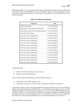
A.9 Addressing
Item Feature Status References Support
ADDR-1 Does each Port have a separate MAC Address? M 7.12.2 Yes [ ]
ADDR-2 Are frames addressed to a MAC Address for a Port and
received from or relayed to the attached LAN submit-
ted to LLC Service User for the destination LLC
Address?
M 7.5,
7.12.2
Yes [ ]
ADDR-3 Are all BPDUs and GARP PDUs transmitted using the
Bridge Spanning Tree Protocol LLC Address?
M 7.12.3,
Table 7-9
Yes [ ]
ADDR-4 Are PDUs addressed to the Bridge Spanning Tree
Protocol Address with an unknown Protocol Identifier
discarded on receipt
M Yes [ ]
ADDR-5 Are all BPDUs transmitted to the Bridge Group
Address?
M 7.12.3,
Table 7-10
Yes [ ]
ADDR-6 Are all GARP PDUs transmitted to the Group Address
assigned for the GARP Application?
M 7.12.3,
Table 12-1
Yes [ ]
ADDR-7 Is it possible to create entries in the Permanent or Fil-
tering Databases for unsupported GARP application
addresses or delete or modify entries for supported
application addresses?
X 7.12.3 No [ ]
ADDR-8 Is the source MAC address of BPDUs and GARP
PDUs for GARP Applications supported by the Bridge
the address of the transmitting Port?
M 7.12.3 Yes [ ]
ADDR-9 Is Bridge Management accessible through a Port using
the MAC Address of the Port?
MGT:O 7.12.4 Yes [ ] No [ ]
ADDR-10 Is a 48-bit Universally Administered MAC Address
assigned to each Bridge as its Bridge Address?
M 7.12.5 Yes [ ]
ADDR-11 Is the Bridge Address the Address of a Port? O 7.12.5 Yes [ ] No [ ]
ADDR-12 Is the Bridge Address the Address of Port 1? ADDR-11: O 7.12.5 Yes [ ] No [ ]
ADDR-13 Are frames addressed to any of the Reserved
Addresses relayed by the Bridge?
X 7.12.6 No [ ]
ADDR-14 Is it possible to delete or modify entries in the
Permanent and Filtering Databases for the Reserved
Addresses?
X 7.12.6 No [ ]](https://image.slidesharecdn.com/802-150416093300-conversion-gate02/85/802-1-d-2004-203-320.jpg)
![IEEE LOCAL AND METROPOLITAN AREA NETWORKS
Std 802.1D-2004
192 Copyright © 2004 IEEE. All rights reserved.
A.10 Rapid Spanning Tree Protocol
Item Feature Status References Support
RSTP-1 Does each Bridge have a unique identifier based on the
Bridge Address, and a unique identifier for each Port?
M 17.2 Yes [ ]
RSTP-2 Can each Port be configured as an edge port by setting the
adminEdgePort parameter?
O 17.3 Yes [ ] No [ ]
RSTP-3 Can each Port be configured to automatically determine if it
an edge port by setting the autoEdgePort parameter?
O 17.3 Yes [ ] No [ ]
RSTP-4 Are learned MAC addresses transferred from a retiring Root
Port to a new Root Port?
O 17.11 Yes [ ] No [ ]
RSTP-5 Is the Spanning Tree Protocol Entity reinitialized if the
Force Protocol Version parameter is modified?
M 17.13 Yes [ ]
RSTP-6 Are spanning tree priority vectors and Port Role assign-
ments recomputed if the Bridge Identifier Priority, Port
Identifier Priority, or Port Path Costs change?
M 17.13 Yes [ ]
RSTP-7 Is the txCount variable for a Port set to zero if the Port’s
Transmit Hold Count is modified?
M 17.13 Yes [ ]
RSTP-8 Are the recommended default values of Migrate Time,
Bridge Hello Time, Bridge Max Age, Bridge Forward
Delay, and Transmit Hold Count used?
O 17.14 Yes [ ] No [ ]
RSTP-9 Can the Bridge Max Age, Bridge Forward Delay, and
Transmit Hold Count parameters be set?
O 17.13, 17.14 Yes [ ] No [ ]
RSTP-10 Can Bridge Max Age, Bridge Forward Delay, Transmit
Hold Count be set to any value in the permitted range?
RSTP-9: M 17.2, 17.15,
Table 17-1
Yes [ ]
N/A[ ]
RSTP-11 Are the relationships between Bridge Hello Time, Bridge
Max Age, and Bridge Forward Delay enforced?
RSTP-9: M 17.14 Yes [ ]
N/A[ ]
RSTP-12 Are the recommended values of Bridge Identifier Priority,
Port Path Costs, and Port Identifier Priorities used?
O 17.14 Yes [ ] No [ ]
RSTP-13 Can the Bridge Identifier Priority, Port Path Costs, and Port
Identifier Priorities be set?
O 17.1, 17.3.1,
17.13, 17.14,
17.18, 17.19
Yes [ ] No [ ]
RSTP-14 Can the Bridge Identifier Priority and Port Identifier Priori-
ties be set to any of the values in the ranges specified?
RSTP-13: M 17.14 Yes [ ]
N/A[ ]
RSTP-15 Can the Port Path Cost for each Port be set to any of the
values in the specified range?
RSTP-13: M 17.14 Yes [ ]
N/A[ ]
RSTP-16 Are Port Path Costs changed automatically by default if port
speeds change?
X 17.14 No [ ]
RSTP-17 Is one instance of the Port Role Selection state machine
implemented for the Bridge; one instance of each of the Port
Timers, Port Receive, Port Protocol Migration, Bridge
Detection, Port Transmit, Port Information, Port Role Tran-
sition, Port State Transition, and Topology Change state
machines implemented per Port; and the referenced defini-
tions and declarations followed for all machines?
M 17.15, 17.28,
17.22, 17.23,
17.24, 17.25,
17.26, 17.27,
17.29, 17.29,
17.30, 17.31
Yes [ ]
RSTP-18 Is it possible to set each Port Protocol Migration state
machine’s mcheck variable?
O 17.19.13 Yes [ ] No [ ]
RSTP-19 Is a single instance of each of the timer variables
implemented per Port?
M 17.22 Yes [ ]
RSTP-20 Are the values for maximum RSTP processing delay and
maximum BPDU transmission delay ever exceeded for any
of the specified external events, actions, internal events, or
transmissions?
X 17.32,
Table 17-5
No [ ]](https://image.slidesharecdn.com/802-150416093300-conversion-gate02/85/802-1-d-2004-204-320.jpg)
![MEDIA ACCESS CONTROL (MAC) BRIDGES IEEE
Std 802.1D-2004
Copyright © 2004 IEEE. All rights reserved. 193
A.11 BPDU Encoding
Item Feature Status References Support
BPDU-1 Do all BPDUs contain an integral number of octets? M 9.1.1 Yes [ ]
BPDU-2 Are all the following BPDU parameter types encoded
as specified?
M 9.1.1, 9.2 Yes [ ]
Protocol Identifiers 9.2.1
Protocol Version Identifiers 9.2.2
BPDU Types 9.2.3
Flags 9.2.4
Bridge Identifiers 9.2.5
Root Path Cost 9.2.6
Port Identifiers 9.2.7
Timer Values 9.2.8
BPDU-3 Do Configuration BPDUs have the format, parameters,
and parameter values specified?
M 9.3.1, 17.21.19 Yes [ ]
BPDU-4 Do Topology Change Notification BPDUs have the
format, parameters, and parameter values specified?
M 9.3.2, 17.21.21 Yes [ ]
BPDU-5 Do Rapid Spanning Tree BPDUs have the format,
parameters, and parameter values specified?
M 9.3.3, 17.21.20 Yes [ ]
BPDU-6 Are received BPDUs validated as and only as
specified?
M 9.3.4 Yes [ ]
BPDU-7 Does the implementation process BPDUs of prior and
possible later protocol versions as specified?
M 9.3.4 Yes [ ]
A.12 Implementation Parameters
Item Feature Status References Support
IMP-1 State the Filtering Database Size. M 7.9 ____ entries
IMP-2 State the Permanent Database Size. M 7.9 ____ entries](https://image.slidesharecdn.com/802-150416093300-conversion-gate02/85/802-1-d-2004-205-320.jpg)

![MEDIA ACCESS CONTROL (MAC) BRIDGES IEEE
Std 802.1D-2004
Copyright © 2004 IEEE. All rights reserved. 195
A.14 Bridge management
Item Feature Status References Support
Are each of the following management operations
supported?
MGT-1 Discover Bridge MGT:M 14.4.1.1 Yes [ ]
MGT-2 Read Bridge MGT:M 14.4.1.2 Yes [ ]
MGT-3 Set Bridge Name MGT:M 14.4.1.3 Yes [ ]
MGT-4 Reset Bridge MGT:M 14.4.1.4 Yes [ ]
MGT-5 Read Port MGT:M 14.4.2.1 Yes [ ]
MGT-6 Set Port Name MGT:M 14.4.2.2 Yes [ ]
MGT-7 Read Forwarding Port Counters MGT:M 14.6.1.1 Yes [ ]
MGT-8 Read Port Default User Priority MGT: M 14.6.2.1 Yes [ ]
MGT-9 Set Port Default User Priority MGT AND MAC-6: M 14.6.2.2 Yes [ ] N/A[ ]
MGT-10 Read Port User Priority Regeneration Table MGT AND RLY-5: M 14.6.2.3 Yes [ ] N/A[ ]
MGT-11 Set Port User Priority Regeneration Table MGT AND RLY-5: M 14.6.2.4 Yes [ ] N/A[ ]
MGT-12 Read Port Traffic Class Table MGT AND TC: M 14.6.3.1 Yes [ ] N/A[ ]
MGT-13 Set Port Traffic Class Table MGT AND TC-3: M 14.6.3.2 Yes [ ] N/A[ ]
MGT-14 Read Outbound Access Priority Table MGT : M 14.6.3.3 Yes [ ]
MGT-15 Read Filtering Database MGT:M 14.7.1.1 Yes [ ]
MGT-16 Set Filtering Database Ageing Time MGT:M 14.7.1.2 Yes [ ]
MGT-17 Read Permanent Database MGT:M 14.7.5.1 Yes [ ]
MGT-18 Create Filtering Entry MGT:M 14.7.6.1 Yes [ ]
MGT-19 Delete Filtering Entry MGT:M 14.7.6.2 Yes [ ]
MGT-20 Read Filtering Entry MGT:M 14.7.6.3 Yes [ ]
MGT-21 Read Filtering Entry Range MGT:M 14.7.6.4 Yes [ ]
MGT-22 Read Spanning Tree Protocol Parameters MGT:M 14.8.1.1 Yes [ ]
MGT-23 Set Spanning Tree Protocol Parameters MGT:M 14.8.1.2 Yes [ ]
MGT-24 Read Port Parameters MGT:M 14.8.2.1 Yes [ ]
MGT-25 Force Port State MGT:M 14.8.2.2 Yes [ ]
MGT-26 Set Port Parameters MGT:M 14.8.2.3 Yes [ ]
MGT-27 Force BPDU Migration Check MGT AND RSTP: M 14.8.2.4 Yes [ ] N/A[ ]
MGT-28 Read GARP Timers MGT AND GARP: M 14.9.1.1 Yes [ ] N/A[ ]
MGT-29 Set GARP Timers MGT AND GARP: M 14.9.1.2 Yes [ ] N/A[ ]
MGT-30 Read GARP Applicant Controls MGT AND GARP: M 14.9.2.1 Yes [ ] N/A[ ]
MGT-31 Set GARP Applicant Controls MGT AND GARP: M 14.9.2.2 Yes [ ] N/A[ ]
MGT-32 Read GARP State MGT AND GARP: M 14.9.3.1 Yes [ ] N/A[ ]](https://image.slidesharecdn.com/802-150416093300-conversion-gate02/85/802-1-d-2004-207-320.jpg)
![IEEE LOCAL AND METROPOLITAN AREA NETWORKS
Std 802.1D-2004
196 Copyright © 2004 IEEE. All rights reserved.
A.15 Remote Management
Item Feature Status References Support
RMGT-1 What Management Protocol standard(s) or specification(s)
are supported?
RMGT:M 5.2
RMGT-2 What standard(s) or specifications for Managed Objects and
Encodings are supported?
RMGT:M 5.2
A.16 Expedited Traffic Classes
Item Feature Status References Support
TC-1 Does the implementation provide more than one transmis-
sion queue for (a) Bridge Port(s)?
TC: M 7.7.3 Yes [ ]
N/A[ ]
TC-2 Is the recommended mapping of user_priority to traffic
classes supported for each Port?
TC: O 7.7.3 Yes [ ] No [ ]
TC-3 Can the traffic class tables be managed? TC: O 7.7.3,
Table 7-2
Yes [ ] No [ ]
TC-4 Is the default algorithm for selecting frames for
transmission supported?
M 7.7.4 Yes [ ]
TC-5 Are additional algorithms for selecting frames for
transmission supported?
O 7.7.4 Yes [ ] No [ ]
A.17 Extended Filtering Services
Item Feature Status References Support
EFS-1 Can Group Registration Entries be created,
updated and removed from the Filtering Data-
base by GMRP?
EFS:M 7.9, 7.9.3, 10 Yes [ ]
N/A[ ]
EFS-2 Can a Static Filtering Entry be created with an
address specification that represents a Group
Address, or All Group Addresses, or All
Unregistered Group Addresses, and with a
control element for each Port that specifies
unconditional forwarding, or unconditional
filtering, or the use of dynamic or default group
filtering information?
EFS:M 7.9.1 Yes [ ]
N/A[ ]
EFS-3 Can a Static Filtering Entry be created with an
address specification that represents an Individ-
ual Address and with a control element for each
Port that specifies unconditional forwarding, or
unconditional filtering?
M 7.9.1 Yes [ ]
EFS-4 Can a Static Filtering Entry be created with an
address specification that represents an Individ-
ual Address and with a control element for each
Port that specifies unconditional forwarding, or
unconditional filtering, or the use of dynamic fil-
tering information?
EFS:O 7.9.1 Yes [ ]
N/A[ ]
No [ ]](https://image.slidesharecdn.com/802-150416093300-conversion-gate02/85/802-1-d-2004-208-320.jpg)
![MEDIA ACCESS CONTROL (MAC) BRIDGES IEEE
Std 802.1D-2004
Copyright © 2004 IEEE. All rights reserved. 197
A.18 GMRP
Item Feature Status References Support
GMRP-1 Does GMRP operate within the Base Spanning
Tree Context, with the GIP Context identifier of 0,
and propagate registration information only on the
active topology?
GMRP:M 10.3.1.1, 10.4.1,
12.2.3, 12.2.4
Yes [ ]
N/A[ ]
GMRP-2 Is the GMRP Address used as the destination MAC
Address in all GMRP protocol exchanges?
GMRP:M 10.3.1.2, 10.4.1,
Table 12-1
Yes [ ]
GMRP-3 Do the PDUs exchanged by the GARP state
machines use the PDU formats, attribute types, and
value encodings defined for GMRP?
GMRP:M 10.3.1, 10.4.1,
12.3, 12.4,
12.10
Yes [ ]
GMRP-4 Are GMRP PDUs and the messages they contain
processed in the order received?
GMRP:M 12.10 Yes [ ]
GMRP-5 Do values of the Group Attribute type include indi-
vidual MAC Addresses?
GMRP:X 10.3.1.4 No [ ]
GMRP-6 Does the GMRP application operate as defined? GMRP:M 10, 10.3, 10.4.1 Yes [ ]
GMRP-7 Can the Static Filtering Entry that specifies All
Groups with Registration Fixed for all Ports be
deleted from the Permanent Database?
GMRP:O 10.3.2.3 Yes [ ] No [ ]
GMRP-8 Is the use of the Restricted Group Registration
parameter supported for each Port?
GMRP:O 10.3.2.2,
10.3.2.3
Yes [ ] No [ ]
GMRP-9 Is the creation or modification of Dynamic Group
Registration Entries restricted as specified if the
Restricted Group Registration control is TRUE?
GMRP-8:O 10.3.2.2,
10.3.2.3
Yes [ ] No [ ]
GMRP-10 Is the Restricted Group Registration control FALSE
for all Ports?
¬GMRP-8:O 10.3.2.3 Yes [ ] No [ ]
GMRP-11 Does the implementation support the operation of
the GARP Applicant, Registrar, and Leave All state
machines?
GMRP:M 10.4.1, 12.7, 13 Yes [ ]](https://image.slidesharecdn.com/802-150416093300-conversion-gate02/85/802-1-d-2004-209-320.jpg)
![IEEE LOCAL AND METROPOLITAN AREA NETWORKS
Std 802.1D-2004
198 Copyright © 2004 IEEE. All rights reserved.
A.19 GARP
Item Feature Status References Support
GARP-1 Does the GARP Entity transmit PDUs to or process PDUs
from any port that is not MAC_Operational or is not
authorized?
GARP:X 12.1 No [ ]
GARP-2 Are GARP PDUs destined for Applications that the Bridge
supports relayed by the Bridge?
GARP:X 7.12.3, 12.4 No [ ]
GARP-3 Are all GARP PDUs destined for Applications that the
Bridge does not support relayed by the Bridge?
M 7.12.3, 12.4,
12.10
Yes [ ]
GARP-4 Do GARP protocol exchanges use LLC Type 1 procedures,
and the Bridge Spanning Tree Protocol LLC address?
GARP:M 12.3, 12.4,
Table 7-9
Yes [ ]
GARP-5 Are received GARP PDUs that are not well formed for the
GARP Applications supported, discarded?
GARP:M 12.3, 12.4,
12.9.1, 12.10
Yes [ ]
GARP-6 Are information items that are received in well formed
PDUs but not understood, individually discarded?
GARP:M 12.9.1, 12.10.3 Yes [ ]
GARP-7 Are the state machines, administrative controls, and proce-
dures required by each supported application implemented
as specified?
GARP:M 12.7, 12.8,
12.9
Yes [ ]
GARP-8 Are the generic elements of GARP PDUs formatted for
transmission and processed on reception by each GARP
Application as specified?
GARP:M 12.10 Yes [ ]
GARP-9 Is the resolution of GARP timers as specified? GARP:M 12.11.2 Yes [ ]](https://image.slidesharecdn.com/802-150416093300-conversion-gate02/85/802-1-d-2004-210-320.jpg)


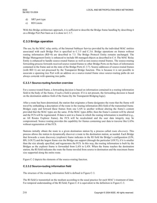

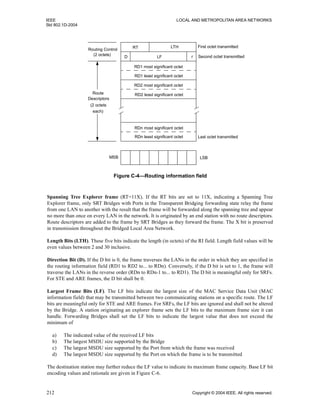


![MEDIA ACCESS CONTROL (MAC) BRIDGES IEEE
Std 802.1D-2004
Copyright © 2004 IEEE. All rights reserved. 229
Annex D
(normative)
PICS Proforma for source-routing transparent bridge operation11
D.1 Introduction
The supplier of a protocol implementation which is claimed to conform to Annex C of this standard shall
complete the following Protocol Implementation Conformance Statement (PICS) proforma, in addition to
the PICS Proforma defined in Annex A (normative). The provisions of A.1 through A.3 apply to the PICS
Proforma defined in this annex.
11
Copyright release for PICS proformas: Users of this standard may freely reproduce the PICS proforma in this annex so that it can be
used for its intended purpose and may further publish the completed PICS.
D.2 Relay and filtering of frames
Item Feature Status References Support
(2a) Is the order of relayed frames of given user
priority preserved?
M C.2.3.1 Yes [ ]
(2b) Are STE, ARE, and SRF Frames submitted to
a MAC entity for transmission only once?
M C.2.3.2 Yes [ ]
(2c) Is the Largest Frame field set by the Bridge as
described in C.3.3.2?
M C.3.3.2 Yes [ ]
(2d) Are frames received with no routing informa-
tion (NSR) processed as described in IEEE Std
802.1D?
M C.3.5 Yes [ ]
(2e) Are received Specifically Routed Frames
(SRF) processed as described in C.3.7.1?
M C.3.7.1 Yes [ ]
(2f) Are received All Routes Explorer (ARE)
Frames processed as described in C.3.7.2?
M C.3.7.2 Yes [ ]
(2g) Does the implementation support option 1 that
allows filtering of frames that have been
through the Bridge before?
O C.3.7.2 Yes [ ] No [ ]
(2h) Does the implementation support option 2 that
allows filtering of frames that have been
through the Bridge before?
O C.3.7.2 Yes [ ] No [ ]
(2i) Are received Spanning Tree Explorer (STE)
frames processed as described in C.3.7.3?
M C.3.7.3 Yes [ ]
(2j) Does the implementation forward explorer
frames (STE, ARE) with LTH = 4 as described
in C.3.7.2 and C.3.7.3?
O C.3.7.2,
C.3.7.3
Yes [ ] No [ ]](https://image.slidesharecdn.com/802-150416093300-conversion-gate02/85/802-1-d-2004-241-320.jpg)
![IEEE LOCAL AND METROPOLITAN AREA NETWORKS
Std 802.1D-2004
230 Copyright © 2004 IEEE. All rights reserved.
D.3 Bridge numbers and LAN IDs
Item Feature Status References Support
(3a) Can the LAN IDs of the attached LANs be
configured in the Bridge?
M C.3.8.1 Yes [ ]
(3b) Can a Bridge Number be assigned to the
Bridge?
M C.3.8.2 Yes [ ]
(3c) Can Bridge management use the duplicate
Bridge number test to check for parallel
Bridges that are assigned the same number?
O C.3.7.4 Yes [ ] No [ ]
D.4 Bridge management
This matter is subject to further ongoing study and resolution.
Item Feature Status References Support
(4a) Bridge Management Operations O C.4 Yes [ ] No [ ]
(4b) Read LF Mode. M C.4.3.1.1 Yes [ ]
(4c) Set LF Mode. M C.4.3.1.2 Yes [ ]
(4d) Read Port Parameters. M C.4.3.2.1 Yes [ ]
(4e) Set ARE RD Limit. M C.4.3.2.4 Yes [ ]
(4f) Specify the max value of the ARE RD Limit in
this implementation.
M C.4.3.2.4 A___
(4g) Set STE RD Limit. M C.4.3.2.4 Yes [ ]
(4h) Specify the max value of the STE RD Limit in
this implementation.
M C.4.3.2.4 A___
(4i) Set LAN Id. M C.4.3.2.2 Yes [ ]
(4j) Set Largest MSDU Size. M C.4.3.2.3 Yes [ ]
(4k) Read SRT Bridge Port Pair Database Size. M C.4.4.1.1 Yes [ ]
(4l) Read SRT Bridge Port Pair Database Entity. M C.4.4.1.2 Yes [ ]
(4m) Set SRT Bridge Port Pair Database Entity. M C.4.4.1.3 Yes [ ]](https://image.slidesharecdn.com/802-150416093300-conversion-gate02/85/802-1-d-2004-242-320.jpg)


![IEEE LOCAL AND METROPOLITAN AREA NETWORKS
Std 802.1D-2004
234 Copyright © 2004 IEEE. All rights reserved.
b) In order to generate a CRC value of length r bits, a generator polynomial, G(x), is used, of degree r
c) The value of the last r bits of M(x) are chosen such that M(x) ÷ G(x) has a remainder of 0 [i.e., M(x)
= 0 mod G(x)].
Messages can be added, in which each coefficient is 0 or 1:
d) M3(x) = M1(x) + M2(x). Messages are added together by bit-wise addition (XOR) of coefficients
with the same bit position (i.e., coefficients with the same exponent).
Subtraction of messages:
e) Addition and subtraction are equivalent operations (as A = A XOR B XOR B); hence, using the
messages in example d) above, M1(x) can be regenerated from M3(x) by adding M2(x).
Linearity:
f) If M(x) = 0 mod G(X), then (M(x) + E(x)) = 0 mod G(x) IFF E(x) = 0 mod G(x). In other words, if
an error pattern, E(x), is added to a message, M(x), then the resultant message will give no
remainder when divided by the generator polynomial if both M(x) and E(x) gave no remainder when
divided by the generator polynomial.
g) xm
M(x) = 0 mod G(x) IFF M(x) = 0 mod G(x). A message can be shifted by adding zero padding
without affecting the integrity of the CRC.
h) Thus, the CRC algorithm has the property that it will detect any burst error, of length r bits or less,
applied to the message, as such an error must result in a nonzero remainder when the message is
divided by the generator polynomial. Alternatively, adding two messages together, both of which
have valid CRCs, results in a message with a valid CRC.
In Ethernet, the algorithm used differs from the standard CRC, and is known as a Frame Check Sequence
(FCS). The FCS is based on the CRC but with the following differences:
— The first 32 bits of M(x) are complemented before the FCS value is calculated.
— A CRC value is calculated, as described above, by dividing the first n-32 bits of M(x) by G(x) and
taking the remainder as the CRC value.
— The CRC value is complemented and inserted as the last 32 bits of M(x).
By application of the addition and linearity rules, item d) and item f) above, the Ethernet frame with its FCS
can be viewed as consisting of the following component messages, added together:
— An n-bit message, M(x), carrying a standard CRC as the last 32 bits.
— An n-bit “FCS adjustment factor,” An(x), which adjusts the CRC to form an FCS.
Figure F-1 illustrates the conversion of a message with a CRC to the equivalent message with an FCS, by the
addition of the adjustment factor. The adjustment factor consists of the following two components:
— The first component, when added to M(x), contributes an adjustment to the CRC, which is equivalent
to the effect of complementing the first 32 bits of M(x) before calculating the CRC bits, and
complements the first 32 bits of M(x).
— The second component, when added to the partially adjusted M(x), restores the first 32 bits of M(x)
to their original value, and complements the (adjusted) CRC to form the final FCS.](https://image.slidesharecdn.com/802-150416093300-conversion-gate02/85/802-1-d-2004-246-320.jpg)