Download to read offline

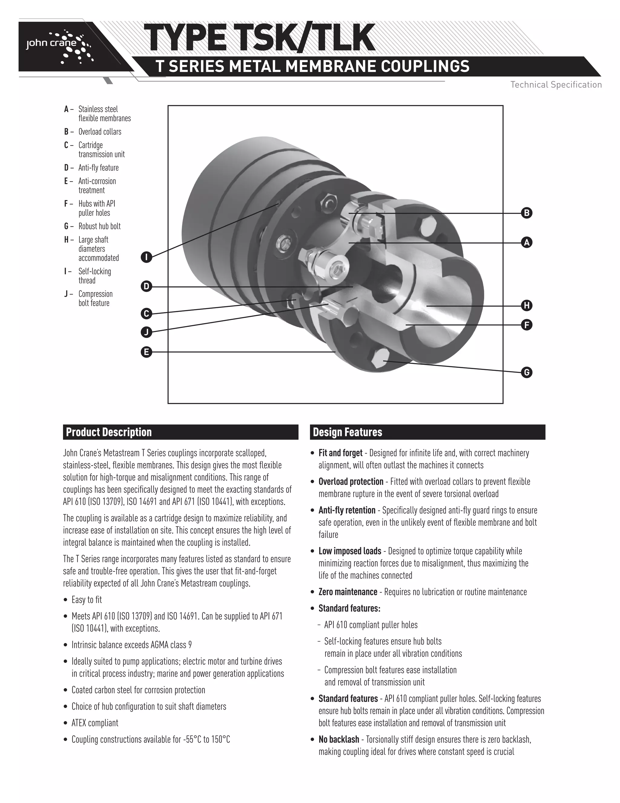
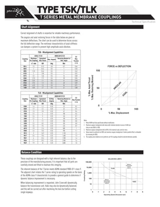

This document provides product information on John Crane's Metastream T Series couplings. The couplings feature scalloped stainless steel flexible membranes designed for high torque and misalignment conditions. They are available in a cartridge design for easy installation and maintenance of integral balance. Standard features include API compliance, intrinsic balance exceeding class 9, and temperature range of -55°C to 150°C. The document describes the selection process and provides technical specifications and dimensions for the T Series couplings.


![Vertical pump maint. update 1026475[1]](https://cdn.slidesharecdn.com/ss_thumbnails/verticalpumpmaint-211027003540-thumbnail.jpg?width=640&height=640&fit=bounds)


