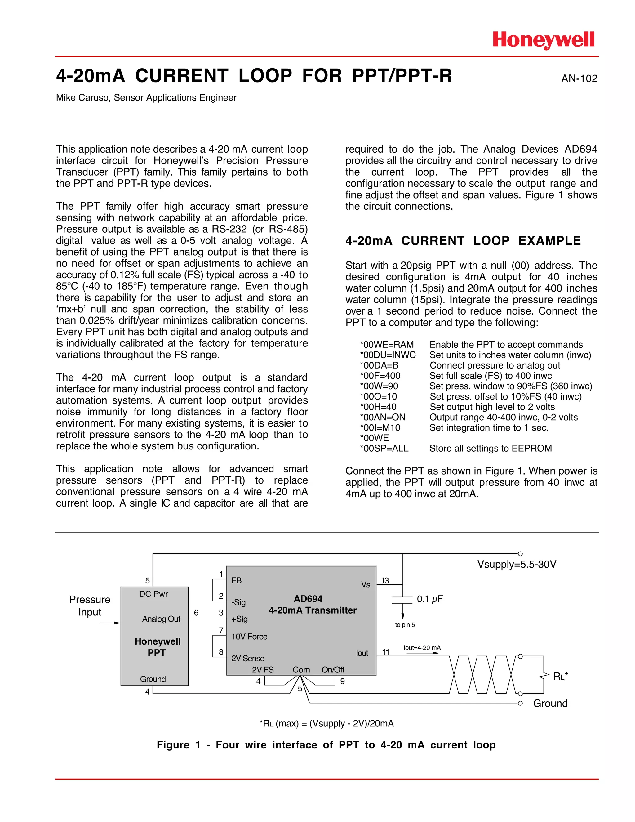
4-20mA CURRENT LOOP FOR PPT/PPT-R AN-102
Mike Caruso, Sensor Applications Engineer
This application note describes a 4-20 mA current loop
interface circuit for HoneywellÕs Precision Pressure
Transducer (PPT) family. This family pertains to both
the PPT and PPT-R type devices.
The PPT family offer high accuracy smart pressure
sensing with network capability at an affordable price.
Pressure output is available as a RS-232 (or RS-485)
digital value as well as a 0-5 volt analog voltage. A
benefit of using the PPT analog output is that there is
no need for offset or span adjustments to achieve an
accuracy of 0.12% full scale (FS) typical across a -40 to
85¡C (-40 to 185¡F) temperature range. Even though
there is capability for the user to adjust and store an
Ômx+bÕ null and span correction, the stability of less
than 0.025% drift/year minimizes calibration concerns.
Every PPT unit has both digital and analog outputs and
is individually calibrated at the factory for temperature
variations throughout the FS range.
The 4-20 mA current loop output is a standard
interface for many industrial process control and factory
automation systems. A current loop output provides
noise immunity for long distances in a factory floor
environment. For many existing systems, it is easier to
retrofit pressure sensors to the 4-20 mA loop than to
replace the whole system bus configuration.
This application note allows for advanced smart
pressure sensors (PPT and PPT-R) to replace
conventional pressure sensors on a 4 wire 4-20 mA
current loop. A single IC and capacitor are all that are
required to do the job. The Analog Devices AD694
provides all the circuitry and control necessary to drive
the current loop. The PPT provides all the
configuration necessary to scale the output range and
fine adjust the offset and span values. Figure 1 shows
the circuit connections.
4-20mA CURRENT LOOP EXAMPLE
Start with a 20psig PPT with a null (00) address. The
desired configuration is 4mA output for 40 inches
water column (1.5psi) and 20mA output for 400 inches
water column (15psi). Integrate the pressure readings
over a 1 second period to reduce noise. Connect the
PPT to a computer and type the following:
*00WE=RAM Enable the PPT to accept commands
*00DU=INWC Set units to inches water column (inwc)
*00DA=B Connect pressure to analog out
*00F=400 Set full scale (FS) to 400 inwc
*00W=90 Set press. window to 90%FS (360 inwc)
*00O=10 Set press. offset to 10%FS (40 inwc)
*00H=40 Set output high level to 2 volts
*00AN=ON Output range 40-400 inwc, 0-2 volts
*00I=M10 Set integration time to 1 sec.
*00WE
*00SP=ALL Store all settings to EEPROM
Connect the PPT as shown in Figure 1. When power is
applied, the PPT will output pressure from 40 inwc at
4mA up to 400 inwc at 20mA.
Ground
Iout=4-20 mA
11
13
RL*
0.1 µFAD694
4-20mA Transmitter
Iout
Vs
Com On/Off2V FS
9
5
4
FB
-Sig
10V Force
2V Sense
7
8
1
2
+Sig
3
Honeywell
PPT
DC Pwr
Ground
Analog Out
5
4
6
Vsupply=5.5-30V
to pin 5
Pressure
Input
*RL (max) = (Vsupply - 2V)/20mA
Figure 1 - Four wire interface of PPT to 4-20 mA current loop
4-20mA CURRENT LOOP FOR PPT/PPT-R
10/96 Helping You Control Your World
If fine adjustments to the offset and span are
necessary, reconnect the computer and use the X=
and Z= commands to adjust the gain and offset
parameters. First, adjust the offset parameter (Z=) with
40 inwc applied. Then adjust the gain parameter (X=)
with 400 inwc applied.
ALARM CONDITION
The AD694 has built in alarms that that warn of an open
circuit at Iout (pin 11) or an attempt to drive the voltage
at Iout higher than Vsupply-2V. The alarm output (pin
10) has an open collector output that drives a logic low
level (typically 0.35V) in the alarm conditions. The drive
current of the alarm pin is limited to about 20mA.
TESTING THE 4-20mA LOOP
The PPT can be configured to drive specific current
levels on the 4-20mA loop (see Figure 2). This may be
useful to test the loop connection or check out the
system interface circuitry. In this mode, the PPT must
be configured to allow the host computer access to
drive the analog output signal. This is done by setting
the PPT Digital and Analog Control command to
DA=G, N, or R. The command sequence below will
configure the PPT in this mode.
*00WE=RAM Enable the PPT to accept commands
*00DA=R Allow N= values to drive DAC output
*00H=40 Set output high level to 2 volts
The DAC output, Analog Out pin 6, will now respond to
computer command inputs using the N= command.
Since the analog output range is set from zero to two
volts, the commands N=0 to N=2000 will drive loop
currents from 4 to 20 mA. The analog output level can
be controlled to the tenth of a millivolt by entering:
*00N=1256.1 to drive 1.2561 volts out the Analog
Out pin on the PPT. This correspond to 14.049mA.
The relation ship between the N= command value and
the Iout current can be expressed as:
Iout (mA) = 4 + [(N=/2000) * 16]
In this mode, the PPT analog output voltage can be
fine adjusted using the X= and Z= commands for
endpoint trimming the 4 and 20 mA levels.
Reference: HoneywellÕs PPT UserÕs Manual for
command descriptions
Customer Service Representative
612-954-2888 fax: 612-954-2582
E-Mail: clr@mn14.ssec.honeywell.com
Web Site: www.ssec.honeywell.com
*00AN=ON Output range to 0-2 volts
*00NE=DAC Enable the write to DAC signal
*00WE
*00SP=ALL Store all settings to EEPROM
Honeywell
PPT
DC Pwr
Ground
Analog Out
5
4
6
*00N=0 (4mA)
*00N=1000 (12mA)
*00N=2000 (20mA)
11
13
RL
0.1 µFAD694
4-20mA Transmitter
Iout
Vs
Com On/Off2V FS
9
5
4
FB
-Sig
10V Force
2V Sense
7
8
1
2
+Sig
3
Vsupply=5.5-30V
Ground
to pin 5
2
RD
Iout=4-20 mA
Figure 2 - Computer control of 4-20 mA current loop

4 20m a-current_loop_for_ppt_ppt-r_an-102 (1)

  • 1.
    4-20mA CURRENT LOOPFOR PPT/PPT-R AN-102 Mike Caruso, Sensor Applications Engineer This application note describes a 4-20 mA current loop interface circuit for HoneywellÕs Precision Pressure Transducer (PPT) family. This family pertains to both the PPT and PPT-R type devices. The PPT family offer high accuracy smart pressure sensing with network capability at an affordable price. Pressure output is available as a RS-232 (or RS-485) digital value as well as a 0-5 volt analog voltage. A benefit of using the PPT analog output is that there is no need for offset or span adjustments to achieve an accuracy of 0.12% full scale (FS) typical across a -40 to 85¡C (-40 to 185¡F) temperature range. Even though there is capability for the user to adjust and store an Ômx+bÕ null and span correction, the stability of less than 0.025% drift/year minimizes calibration concerns. Every PPT unit has both digital and analog outputs and is individually calibrated at the factory for temperature variations throughout the FS range. The 4-20 mA current loop output is a standard interface for many industrial process control and factory automation systems. A current loop output provides noise immunity for long distances in a factory floor environment. For many existing systems, it is easier to retrofit pressure sensors to the 4-20 mA loop than to replace the whole system bus configuration. This application note allows for advanced smart pressure sensors (PPT and PPT-R) to replace conventional pressure sensors on a 4 wire 4-20 mA current loop. A single IC and capacitor are all that are required to do the job. The Analog Devices AD694 provides all the circuitry and control necessary to drive the current loop. The PPT provides all the configuration necessary to scale the output range and fine adjust the offset and span values. Figure 1 shows the circuit connections. 4-20mA CURRENT LOOP EXAMPLE Start with a 20psig PPT with a null (00) address. The desired configuration is 4mA output for 40 inches water column (1.5psi) and 20mA output for 400 inches water column (15psi). Integrate the pressure readings over a 1 second period to reduce noise. Connect the PPT to a computer and type the following: *00WE=RAM Enable the PPT to accept commands *00DU=INWC Set units to inches water column (inwc) *00DA=B Connect pressure to analog out *00F=400 Set full scale (FS) to 400 inwc *00W=90 Set press. window to 90%FS (360 inwc) *00O=10 Set press. offset to 10%FS (40 inwc) *00H=40 Set output high level to 2 volts *00AN=ON Output range 40-400 inwc, 0-2 volts *00I=M10 Set integration time to 1 sec. *00WE *00SP=ALL Store all settings to EEPROM Connect the PPT as shown in Figure 1. When power is applied, the PPT will output pressure from 40 inwc at 4mA up to 400 inwc at 20mA. Ground Iout=4-20 mA 11 13 RL* 0.1 µFAD694 4-20mA Transmitter Iout Vs Com On/Off2V FS 9 5 4 FB -Sig 10V Force 2V Sense 7 8 1 2 +Sig 3 Honeywell PPT DC Pwr Ground Analog Out 5 4 6 Vsupply=5.5-30V to pin 5 Pressure Input *RL (max) = (Vsupply - 2V)/20mA Figure 1 - Four wire interface of PPT to 4-20 mA current loop
  • 2.
    4-20mA CURRENT LOOPFOR PPT/PPT-R 10/96 Helping You Control Your World If fine adjustments to the offset and span are necessary, reconnect the computer and use the X= and Z= commands to adjust the gain and offset parameters. First, adjust the offset parameter (Z=) with 40 inwc applied. Then adjust the gain parameter (X=) with 400 inwc applied. ALARM CONDITION The AD694 has built in alarms that that warn of an open circuit at Iout (pin 11) or an attempt to drive the voltage at Iout higher than Vsupply-2V. The alarm output (pin 10) has an open collector output that drives a logic low level (typically 0.35V) in the alarm conditions. The drive current of the alarm pin is limited to about 20mA. TESTING THE 4-20mA LOOP The PPT can be configured to drive specific current levels on the 4-20mA loop (see Figure 2). This may be useful to test the loop connection or check out the system interface circuitry. In this mode, the PPT must be configured to allow the host computer access to drive the analog output signal. This is done by setting the PPT Digital and Analog Control command to DA=G, N, or R. The command sequence below will configure the PPT in this mode. *00WE=RAM Enable the PPT to accept commands *00DA=R Allow N= values to drive DAC output *00H=40 Set output high level to 2 volts The DAC output, Analog Out pin 6, will now respond to computer command inputs using the N= command. Since the analog output range is set from zero to two volts, the commands N=0 to N=2000 will drive loop currents from 4 to 20 mA. The analog output level can be controlled to the tenth of a millivolt by entering: *00N=1256.1 to drive 1.2561 volts out the Analog Out pin on the PPT. This correspond to 14.049mA. The relation ship between the N= command value and the Iout current can be expressed as: Iout (mA) = 4 + [(N=/2000) * 16] In this mode, the PPT analog output voltage can be fine adjusted using the X= and Z= commands for endpoint trimming the 4 and 20 mA levels. Reference: HoneywellÕs PPT UserÕs Manual for command descriptions Customer Service Representative 612-954-2888 fax: 612-954-2582 E-Mail: clr@mn14.ssec.honeywell.com Web Site: www.ssec.honeywell.com *00AN=ON Output range to 0-2 volts *00NE=DAC Enable the write to DAC signal *00WE *00SP=ALL Store all settings to EEPROM Honeywell PPT DC Pwr Ground Analog Out 5 4 6 *00N=0 (4mA) *00N=1000 (12mA) *00N=2000 (20mA) 11 13 RL 0.1 µFAD694 4-20mA Transmitter Iout Vs Com On/Off2V FS 9 5 4 FB -Sig 10V Force 2V Sense 7 8 1 2 +Sig 3 Vsupply=5.5-30V Ground to pin 5 2 RD Iout=4-20 mA Figure 2 - Computer control of 4-20 mA current loop