3台以上のArduinoでのSPI通信 ver.1 =2017-07-20
以下の記事を参考にした
How do you use SPI on an Arduino? - Arduino Stack Exchange
https://arduino.stackexchange.com/questions/16348/how-do-you-use-spi-on-an-arduino
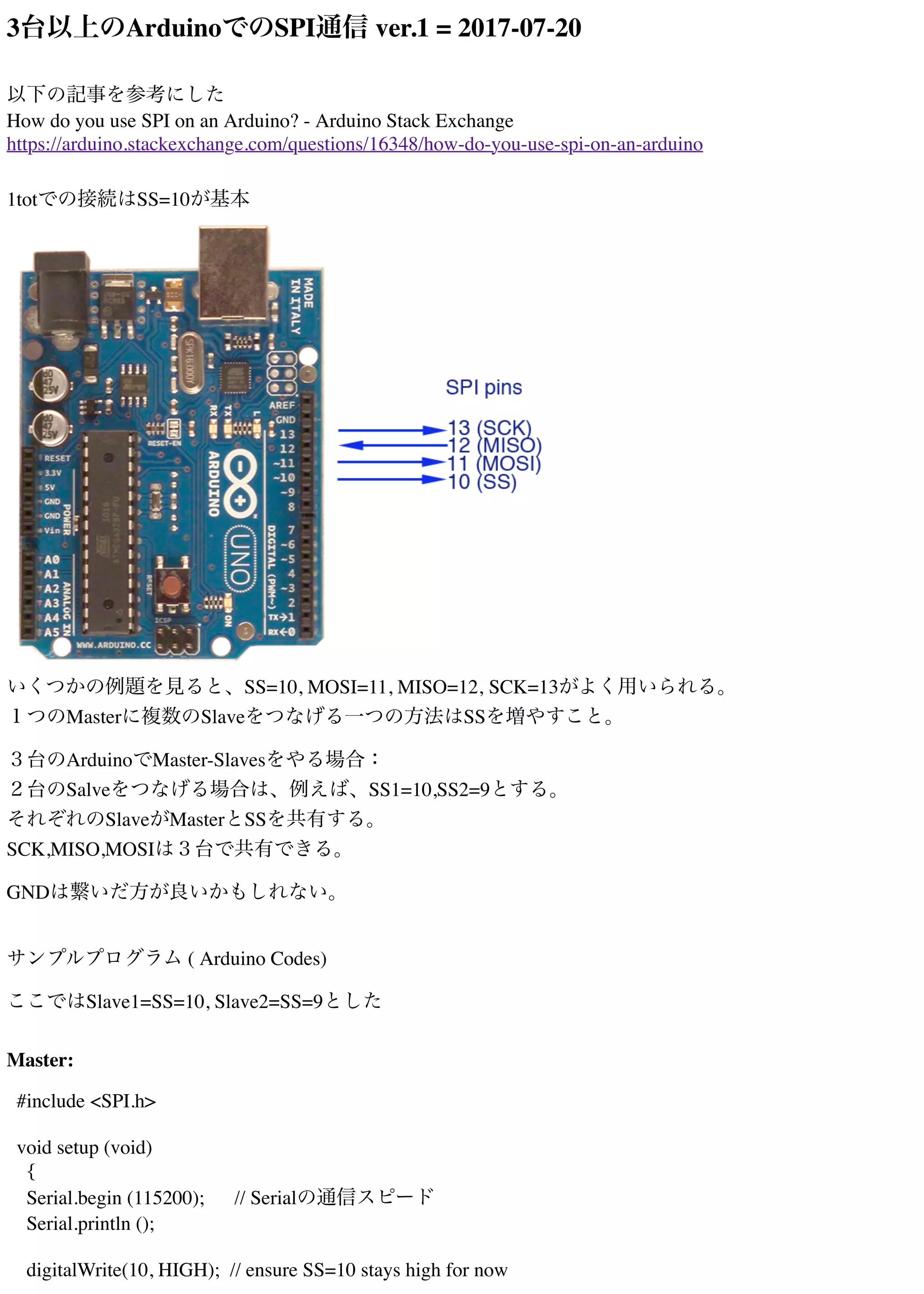
1totでの接続はSS=10が基本
いくつかの例題を見ると、SS=10, MOSI=11, MISO=12, SCK=13がよく用いられる。
1つのMasterに複数のSlaveをつなげる一つの方法はSSを増やすこと。
3台のArduinoでMaster-Slavesをやる場合:
2台のSalveをつなげる場合は、例えば、SS1=10,SS2=9とする。
それぞれのSlaveがMasterとSSを共有する。
SCK,MISO,MOSIは3台で共有できる。
GNDは繋いだ方が良いかもしれない。
サンプルプログラム ( Arduino Codes)
ここではSlave1=SS=10, Slave2=SS=9とした
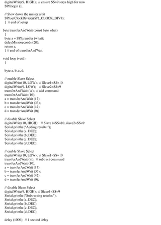
Master:
#include <SPI.h>
void setup (void)
{
Serial.begin (115200); // Serialの通信スピード
Serial.println ();
digitalWrite(10, HIGH); // ensure SS=10 stays high for now
2.
digitalWrite(9, HIGH); //ensure SS=9 stays high for now
SPI.begin ();
// Slow down the master a bit
SPI.setClockDivider(SPI_CLOCK_DIV8);
} // end of setup
byte transferAndWait (const byte what)
{
byte a = SPI.transfer (what);
delayMicroseconds (20);
return a;
} // end of transferAndWait
void loop (void)
{
byte a, b, c, d;
// enable Slave Select
digitalWrite(10, LOW); // Slave1=SS=10
digitalWrite(9, LOW); // Slave2=SS=9
transferAndWait ('a'); // add command
transferAndWait (10);
a = transferAndWait (17);
b = transferAndWait (33);
c = transferAndWait (42);
d = transferAndWait (0);
// disable Slave Select
digitalWrite(10, HIGH); // Slave1=SS=10, slave2=SS=9
Serial.println ("Adding results:");
Serial.println (a, DEC);
Serial.println (b, DEC);
Serial.println (c, DEC);
Serial.println (d, DEC);
// enable Slave Select
digitalWrite(10, LOW); // Slave1=SS=10
transferAndWait ('s'); // subtract command
transferAndWait (10);
a = transferAndWait (17);
b = transferAndWait (33);
c = transferAndWait (42);
d = transferAndWait (0);
// disable Slave Select
digitalWrite(9, HIGH); // Slave1=SS=9
Serial.println ("Subtracting results:");
Serial.println (a, DEC);
Serial.println (b, DEC);
Serial.println (c, DEC);
Serial.println (d, DEC);
delay (1000); // 1 second delay
3.
} // endof loop
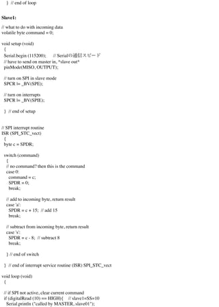
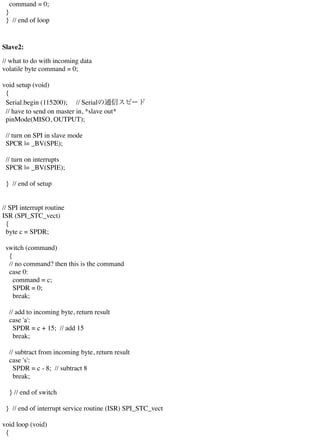
Slave1:
// what to do with incoming data
volatile byte command = 0;
void setup (void)
{
Serial.begin (115200); // Serialの通信スピード
// have to send on master in, *slave out*
pinMode(MISO, OUTPUT);
// turn on SPI in slave mode
SPCR |= _BV(SPE);
// turn on interrupts
SPCR |= _BV(SPIE);
} // end of setup
// SPI interrupt routine
ISR (SPI_STC_vect)
{
byte c = SPDR;
switch (command)
{
// no command? then this is the command
case 0:
command = c;
SPDR = 0;
break;
// add to incoming byte, return result
case 'a':
SPDR = c + 15; // add 15
break;
// subtract from incoming byte, return result
case 's':
SPDR = c - 8; // subtract 8
break;
} // end of switch
} // end of interrupt service routine (ISR) SPI_STC_vect
void loop (void)
{
// if SPI not active, clear current command
if (digitalRead (10) == HIGH){ // slave1=SS=10
Serial.println ("called by MASTER, slave01");
4.
command = 0;
}
}// end of loop
Slave2:
// what to do with incoming data
volatile byte command = 0;
void setup (void)
{
Serial.begin (115200); // Serialの通信スピード
// have to send on master in, *slave out*
pinMode(MISO, OUTPUT);
// turn on SPI in slave mode
SPCR |= _BV(SPE);
// turn on interrupts
SPCR |= _BV(SPIE);
} // end of setup
// SPI interrupt routine
ISR (SPI_STC_vect)
{
byte c = SPDR;
switch (command)
{
// no command? then this is the command
case 0:
command = c;
SPDR = 0;
break;
// add to incoming byte, return result
case 'a':
SPDR = c + 15; // add 15
break;
// subtract from incoming byte, return result
case 's':
SPDR = c - 8; // subtract 8
break;
} // end of switch
} // end of interrupt service routine (ISR) SPI_STC_vect
void loop (void)
{
5.
// if SPInot active, clear current command
if (digitalRead (9) == HIGH){ // slave2=SS=9
Serial.println ("called by MASTER, slave02");
delay(500);
command = 0;
}
} // end of loop
MacでのArduinoとのシリアル通信
以下のコマンドをターミナルで実行すると、Arduinoがつながったポートがわかる:
$ ls /dev/tty.*
/dev/tty.Bluetooth-Incoming-Port /dev/tty.usbmodem14121
/dev/tty.iPad-WirelessiAP /dev/tty.usbmodem14131
/dev/tty.lpss-serial1 /dev/tty.usbmodem14141
/dev/tty.lpss-serial2
ここで
/dev/tty.usbmodem14121, /dev/tty.usbmodem14131, /dev/tty.usbmodem14141
がArduinoが接続されたポート
Arduino IDEを使っても、確認できる

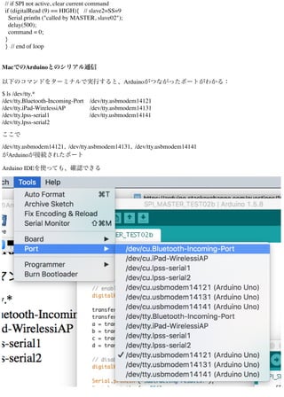
![シリアルポートからデータを読み込むpythonプログラム (1) read_serial01.py
import serial, sys
strPort = sys.argv[1]
#ser = serial.Serial(
# port=strPort,
# baudrate=sys.argv[2],
# parity=serial.PARITY_NONE,
# stopbits=serial.STOPBITS_ONE,
# bytesize=serial.EIGHTBITS,
# timeout=0)
ser=serial.Serial(strPort, sys.argv[2])
print("connected to: " + ser.portstr)
count=1
while True:
line = ser.readline()
print(str(count) + str(': ') + line )
count = count+1
ser.close()
使い方:
ターミナルでArduinoがつながったシリアルポートを確認して、例えば、ターミナルで次のように実行
する
$ python read_serial01.py "/dev/tty.usbmodem14121" 115200
"/dev/tty.usbmodem14121"がポートナンバー。115200は通信スピード。
1つのウィンドウで1つのポートを読み込む。2つ以上は、2つ以上のウィンドウを開いて、一つず
つ表示。](https://image.slidesharecdn.com/3arduinospi2017-07-20-170720035024/85/3-arduino-spi-2017-07-20-6-320.jpg)
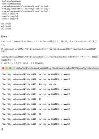
![3つのシリアルポートからデータを読み込むpythonプログラム (2) read_serial02.py
import serial, sys
#ser = serial.Serial(
# port=strPort,
# baudrate=sys.argv[2],
# parity=serial.PARITY_NONE,
# stopbits=serial.STOPBITS_ONE,
# bytesize=serial.EIGHTBITS,
# timeout=0)
ser1=serial.Serial(sys.argv[1], sys.argv[4])
ser2=serial.Serial(sys.argv[2], sys.argv[4])
ser3=serial.Serial(sys.argv[3], sys.argv[4])
print("connected to: " + ser1.portstr)
print("connected to: " + ser2.portstr)
print("connected to: " + ser3.portstr)
count1=1
count2=1
count3=1
while True:
line1 = ser1.readline()](https://image.slidesharecdn.com/3arduinospi2017-07-20-170720035024/85/3-arduino-spi-2017-07-20-7-320.jpg)