The document provides calibration procedures for the NI PXIe-5170R oscilloscope. It includes instructions for characterizing test equipment, verifying specifications, making adjustments, and re-verifying. Key steps include testing the timebase accuracy, DC accuracy, AC amplitude accuracy, and bandwidth using a calibration system with a signal generator, power sensor and oscilloscope calibrator. Limits are provided for as-found and as-left tolerances.
Transcat + Emerson Webinar: Maximize Safety and Reliability with the Only Wir...Transcat
Join us as Transcat and Kevin Thomas, Emerson's Level Instrumentation Expert, host this informative webinar. In this webinar you will learn about: overfill prevention, how to be alerted to issues such as coating or corrosion, how to monitor and control using the 2140 series Level Detectors, and how to detect sand & sediment with these level detectors.
Shop Rosemount Products: http://www.transcat.com/brand/rosemount?cat=3
The EL2200 series of electromagnetic flowmeters represent the state of the art for the accurate measurement for water cycle and process applications. This new generation flowmeter utilizes an innovative structure to route the electromagnetic signal generated by the electrodes, providing a flowmeter with an extremely wide measurement range. The new EL Series meters are capable of a measurement range up to 1000:1.
The new PowerVUE™ design utilizes the same rugged Hagan actuator and frame construction, combined with the accuracy and reliability of the Fisher FieldVUE DVC6000 Digital Valve Controller. The pneumatic power positioner remains the most reliable and cost-effective method of actuation. Torque ranges are from 400 ft-lbs to 4,600 ft.-lbs.
#Draeger launches the new Pulsar 7000 line of sight (LOS) gas detector for the detection of Hydrocarbons. SIL2 (SC3), DNV & user friendly with plenty of new features (status LED's), configurable Range & Signals, HART 7 compatible with 3rd party HART communicator. Distance covered 4-60 & 30-120 meters
Overhead & Underground Electric Safety Webinar Presented by AmprobeTranscat
Join presenter Marco Rossi from Amprobe to learn more about overhead and underground electric safety. This webinar will offer a comprehensive look at the current safety guidelines, discuss best practices, and teach you the basics of underground tracing techniques and equipment functionality.
Advances in Phased Array Inspection of API 620 LNG TanksOlympus IMS
Improvements in PA Inspection of LNG Tanks
Presentation Objectives:
- Overview of the equipment and hardware that make up an LNG phased
array inspection system
- Overview of the unique considerations for inspection of 9% Ni to I-625
dissimilar metal welds typical of LNG tank shell fabrication
- Overview of API 620 and ASME V code requirements and references
relative to LNG tank shell inspection
- Overview of the LNG quad-probe phased array inspection strategy
- Overview of personnel requirements and production expectations
Learn more at: https://www.olympus-ims.com/en/phasedarray/
Yokogawa manufactures several variants of sanitary pressure transmitters for industrial applications in food, pharma, and other industries. Leading edge measurement technology.
Vibration testing fixtures the vibration testing blindspotNeelHope
Presentation at A2LA Tech Forum 2021 by Paragon Systems Testing to answer the why we perform vibration tests, what we need to perform a vibration test, ISO 17025 definition of equipment, how vibration fixture affects a vibration test result and vibration fixture blind spot
https://paragonsystems.net/testing-services/vibration-fixtures-manufacturer/
IRZ artificial lift solutions 1.3 july 2016Ivan Isaev
IRZ artificial lift solutions:
- Downhole monitoring systems for ESP (downhole sensor, surface acquisition unit);
- Downhole monitoring systems with flow meter;
- Downhole monitoring systems for dual ESP production;
- Electromagnetic anti-scaling downhole system for ESP;
- Downhole monitoring systems for rod-pumps/ PCP/ Gas Lift/ Flowing Wells;
- Сontrol stations (VSD, Soft Starters, Switchboards) for ESP, PCP, rod-pumps.
Brosur 5128A RHapid-Cal Humidity Generator - Fluke Calibration. Fast, portable humidity probe and logger calibration with accredited 1% RH system accuracy.
Info lebih lanjut hubungi Siwali Swantika, Jakarta : 021-45850618 | Surabaya : 031-8421264. Distributor Fluke Calibration di Indonesia
Series One Safety Transmitter, Pressure and Temperature SwitchIves Equipment
The One Series Safety Transmitter is a transmitter-switch for monitoring pressure or temperature and meets the requirements of SIL 2 for random integrity at HFT = 0, SIL 3 for random integrity at HFT = 1 and SIL 3 for systematic capability. The One Series Safety Transmitter incorporates UE’s patented IAW self diagnostics, redundant and diverse signal processing and software algorithms to detect abnormalities in the process and internal faults. The design is based on a powerful microprocessor that provides an extremely fast response time for emergency shutdown situations.
Azbil North America recently added the AX series of multivariable vortex flowmeters for industrial process measurement and control to their product offering. The instrument combines temperature, pressure and velocity measurement in a single instrument to provide accurate mass flow measurement of gases, liquids and steam.
NRP is a multifunction unit charged with R410a gas for the simultaneous but independent production of hot and cold water. The 2-pipe units are designed for applications where cold/hot water and domestic hot water is required throughout the year. The 4-pipe units are designed for systems where hot and cold water may be requested simultaneously. The machine is fitted with axial fans with reduced sound emissions, and scroll compressors with a high yield and low electricity absorption. The NRP has 3 heat exchangers: one on the environment side (finned pack copper/aluminium) and 2 indoor (shell and tube). NRP is ideal for small/medium-sized services in residential, commercial and industrial contexts. There are 3 versions - standard, low noise and high efficiency.
Foxboro Magnetic Flowmeter for Chemical and Process IndustriesSwanson Flo
Based on Faraday’s law of induction, Foxboro magnetic meters are a reliable ow measurement solution with a lower cost of ownership and maintenance, as well as eld-proven stability to maximize the availability of ow measurement.
With a wide range of liners and electrodes, the 9700A owtube is ideal for the Chemical and Process industries. In combination with the IMT30A, IMT31A and IMT33A transmitters, Foxboro offers an innovative solution designed to meet the demands for all chemical applications such as:
• Clean liquids
• Mixing of chemicals
• Demanding applications including corrosive, abrasive liquids • Rapid variation of the pH value
• For slurries and pastes with high solids content
• Drilling applications, mining slurries with large particles
The Brooks® Ar-MiteTM is a reliable, low flow metal tube flowmeter with 316L stainless steel wetted parts. The magnetically coupled indicator provides a highly reliable method of indication. This model is a practical and economical approach to low flow rate indication for high pressure and difficult to handle fluids. Optional accessories include 4-20 mA output, Needle Valve, Flow Controllers and Alarms.
BharatPlaza, Jodhpur, Rajasthan (India) is a one of the leading Designer, Manufacturers, Retailer & Exporters. We offer Sarees, Lehengas, Sherwanis, Kurta Pyjamas, and Jewelry, Accessories with awesome price and Finest Quality
www.bharatplaza.com
Kurta Pyjama and Semi Sherwani are the famous dresses of India for wedding ceremonies and festivals. We have great variety of outfits from simple to rich ones with antique work and eye-catching embroidery. Stunning ensembles are created on raw silk, cot silk, silk jacquard, brocade silk base and coming with very well complimenting stole. Gorgeous outfit is specially designed for brothers and friends of bride and groom. You will definitely love our dazzling collection and reasonable prices...
www.bharatplaza.com
BharatPlaza, Jodhpur, Rajasthan (India) is a one of the leading Designer, Manufacturers, Retailer & Exporters. We offer Sarees, Lehengas, Sherwanis, Kurta Pyjamas, and Jewelry, Accessories with awesome price and Finest Quality
Analisi della filosofia si cui si è basato lo sviluppo della norma MIL-STD-461 dalla sua nascita fino alla versione attuale -461G. Pubblicata in occasione del seminario MIL nel 2017.
Analisi delle prove di suscettibilità condotta nell'ambito della norma MIL-STD-461G e paragone con le normative precedenti. Pubblicata in occasione del seminario MIL nel 2017.
Cox Precision metering products by Badger Meter provide flow measurement solutions for the test and measurement market and precision industrial applications.
Essential quality criteria for planning and validation of PROFINET networks
For PROFINET devices the quality criteria that are checked within the scope of the device certification are described in published specifications, standards and test specifications. Interoperability is protected by both the specification and the test procedures in the cooperation of the devices. From practical experience in the realization of network arrangements it appears that beside the device qualities also the planning quality and the quality of the validation of a whole arrangement can have an influence on the functionality.
In the task force CB / PG3 "Installation Guidelines" the suitable planning directives and introduction directives are now integrated into the quality criteria for the planning and validation of the PROFINET networks. The methods, measuring procedures and also the background will be fully explained.
The Industry-leading electrical power distribution systems. Explore Messung Wöhner track busbar. Our Industrial-grade power distribution reduces downtime.
Industrial Temperature Calibration Selection Guide by Fluke CalibrationFluke Calibration
The Industrial Temperature Calibration Selection Guide includes information on:
Field metrology wells
Infrared calibrators
Handheld and field dry-wells
Micro-baths
Environmental monitoring
Thermometer readouts
Reference sensors Industrial temperature calibration selection guide Tools
Using EMI Analyst™ to Perform Method CS114 Analyses for MIL-STD-461EMI Software LLC
CS114 is a conducted susceptibility test method imposed on nearly all military and space electronics. EMI Analyst manages its conditional injection levels effortlessly.
1. CALIBRATION PROCEDURE
NI PXIe-5170R
This document contains the verification and adjustment procedures for the NI PXIe-5170R
(NI 5170R). Refer to ni.com/calibration for more information about calibration solutions.
Contents
Required Software.....................................................................................................................1
Related Documentation.............................................................................................................2
Test Equipment..........................................................................................................................2
Test Conditions..........................................................................................................................5
Password................................................................................................................................... 6
Calibration Interval................................................................................................................... 6
As-Found and As-Left Limits...................................................................................................6
Measurement Uncertainty.........................................................................................................6
Calibration Overview................................................................................................................6
Test System Characterization....................................................................................................7
Zeroing the Power Sensor.................................................................................................7
Characterizing Power Splitter Amplitude Imbalance....................................................... 7
Verification..............................................................................................................................10
Verifying Timebase Accuracy.........................................................................................11
Verifying DC Accuracy...................................................................................................12
Verifying AC Amplitude Accuracy.................................................................................14
Verifying Flatness and Bandwidth.................................................................................. 18
Adjustment..............................................................................................................................21
Adjusting DC.................................................................................................................. 21
Adjusting Timebase.........................................................................................................22
Reverification..........................................................................................................................23
Updating Verification Date and Time..................................................................................... 23
Worldwide Support and Services............................................................................................23
Required Software
Calibrating the NI 5170R requires you to install the following software on the calibration
system:
• LabVIEW Instrument Design Libraries for Reconfigurable Oscilloscopes. The NI 5170R
was first supported in LabVIEW Instrument Design Libraries for Reconfigurable
Oscilloscopes 14.0.
You can download all required software from ni.com/downloads.
2. Related Documentation
You might find the following documents helpful as you perform the calibration procedure:
• NI PXIe-5170R Getting Started Guide
• NI Reconfigurable Oscilloscopes Help
• NI PXIe-5170R Specifications
The latest versions of these documents are available from ni.com/manuals.
Test Equipment
This section lists the equipment required to calibrate the NI 5170R.
If you do not have the recommended equipment, select a substitute calibration standard using
the specifications listed in the table.
Table 1. NI 5170R Test Equipment
Equipment Recommended
Model
Where Used Minimum Requirements
Oscilloscope
calibrator
Fluke 9500B/600
with Fluke 9530
Active Head
Verifications:
• Timebase
accuracy
• DC accuracy
Adjustments:
• Timebase
• DC
Sine Wave Amplitude:
0.9 Vpk-pk at 11 MHz into
50 Ω
Sine Wave Frequency
Accuracy: 0.25 ppm at
11 MHz
DC Output Range: ±40 mV
to ±2.5 V into 50 Ω
DC Output Accuracy:
±(0.025% of output +
25 µV) into 50 Ω
SMA (m)-to-
BNC (f) adapter
Fairview Microwave
SM4723
Verifications:
• Timebase
accuracy
• DC accuracy
Adjustments:
• Timebase
• DC
Frequency range: DC to
11 MHz
Impedance: 50 Ω
2 | ni.com | NI PXIe-5170R Calibration Procedure
4. Table 1. NI 5170R Test Equipment (Continued)
Equipment Recommended
Model
Where Used Minimum Requirements
Power sensor Rohde & Schwarz
(R&S) NRP-Z91
Test system
characterization
Verifications:
• Flatness and
bandwidth
Range: -15 dBm to 5 dBm
Frequency range: 50 kHz to
275 MHz
Absolute Power Accuracy:
<0.048 dB for <100 MHz,
<0.063 dB for 100 MHz to
275 MHz
Relative Power Accuracy:
<0.022 dB for <100 MHz,
<0.031 dB for 100 MHz to
275 MHz
VSWR: <1.11
Signal generator Rhode & Schwartz
SMA100A
Test system
characterization
Verifications:
• Flatness and
bandwidth
Frequency range: 50 kHz to
275 MHz
Amplitude range: -7 dBm
to 8 dBm
Harmonics: <-30 dBc
Power splitter Aeroflex/Weinschel
1593
Test system
characterization
Verifications:
• Flatness and
bandwidth
Frequency range: 50 kHz to
275 MHz
VSWR: <1.08
Amplitude tracking:
<0.5 dB
50 Ω SMA
terminator (f)
Fairview Microwave
ST1825F
Test system
characterization
Frequency range: DC to
275 MHz
VSWR: <1.05
Impedance: 50 Ω
4 | ni.com | NI PXIe-5170R Calibration Procedure
6. information about cooling, refer to the Maintain Forced-Air Cooling Note to Users
document available at ni.com/manuals.
• Plug the chassis and the instrument standard into the same power strip to avoid ground
loops.
Password
The default password for password-protected operations is NI.
Calibration Interval
Recommended calibration interval 2 years
As-Found and As-Left Limits
The as-found limits are the published specifications for the NI 5170R. NI uses these limits to
determine whether the NI 5170R meets the device specifications when it is received for
calibration. Use the as-found limits during initial verification.
The as-left calibration limits are equal to the published NI specifications for the NI 5170R, less
guard bands for measurement uncertainty, temperature drift, and drift over time. NI uses these
limits to reduce the probability that the instrument will be outside the published specification
limits at the end of the calibration cycle. Use the as-left limits when performing verification
after adjustment.
Measurement Uncertainty
Measurement uncertainty was calculated in accordance with the method described in ISO
GUM (Guide to the Expression of Uncertainty in Measurement), for a confidence level of
95%. The expressed uncertainty is based on the recommended measurement methodology,
standards, metrology best practices and environmental conditions of the National Instruments
laboratory. It should be considered as a guideline for the level of measurement uncertainty that
can be achieved using the recommended method. It is not a replacement for the user
uncertainty analysis that takes into consideration the conditions and practices of the individual
user.
Calibration Overview
Install the device and configure it in Measurement & Automation Explorer (MAX) before
calibrating.
Calibration includes the following steps:
6 | ni.com | NI PXIe-5170R Calibration Procedure
8. 3. Connect the RF OUT connector of the signal generator to the input port of the power
splitter using an SMA (f)-to-N (m) adapter and an SMA (m)-to-SMA (m) cable.
4. Connect an SMA (m)-to-SMA (m) adapter to one of the power splitter output ports. Refer
to this assembly as splitter output 1.
5. Connect the 50 Ω SMA terminator (f) to splitter output 1.
6. Connect the other SMA (m)-to-SMA (m) adapter to the other output port of the power
splitter. Refer to this assembly as splitter output 2.
7. Connect the power sensor to splitter output 2.
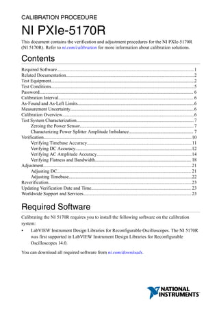
The following figure illustrates the hardware setup.
Figure 1. Connection Diagram for Measuring at Splitter Output 2
1
3
867654
2
1. Signal Generator
2. SMA (f)-to-N (m) Adapter
3. SMA (m)-to-SMA (m) Cable
4. Power Sensor
5. SMA (f)-to-N (f) Adapter
6. SMA (m)-to-SMA (m) Adapter
7. Power Splitter
8. 50 Ω SMA Terminator (f)
8. Configure the signal generator to generate a sine waveform with the following
characteristics:
• Frequency: the Test Point Frequency value from the Power Splitter Characterization
table
• Amplitude level: the Test Point Amplitude value from the Power Splitter
Characterization table
8 | ni.com | NI PXIe-5170R Calibration Procedure
10. 16. Configure the power sensor to correct for the Test Point Frequency value using the power
sensor frequency correction function.
17. Use the power sensor to measure the power in dBm.
18. Repeat steps 15 through 17 for each configuration in the Power Splitter Characterization
table, recording each result as splitter output 1 power, where each configuration has a
corresponding value.
19. Calculate the splitter imbalance for each frequency point using the following equation:
splitter imbalance = splitter output 2 power - splitter output 1 power
20. Disconnect the 50 Ω SMA terminator (f) from splitter output 2. Refer to the remaining
assembly as the power sensor assembly. The power sensor assembly will be used in the
Verifying Flatness and Bandwidth procedure.
Related Information
Verifying Flatness and Bandwidth on page 18
Follow this procedure to verify the analog flatness and bandwidth accuracy of the
NI 5170R by generating a sine wave and comparing the amplitude measured by the
NI 5170R to the amplitude measured by the power sensor.
Verification
This section provides instructions for verifying the device specifications.
Verification of the NI 5170R is complete only after you have successfully completed all tests
in this section using the As-Found Limits.
Refer to the following figure for the names and locations of the NI 5170R front panel
connectors. You can find information about the functions of these connectors in the device
getting started guide.
10 | ni.com | NI PXIe-5170R Calibration Procedure
12. 1. Connect the SMA (m)-to-BNC (f) adapter to channel 0 of the NI 5170R.
2. Connect the calibrator test head to the SMA (m)-to-BNC (f) adapter.
3. Configure the NI 5170R with the following settings:
• Bandwidth: Full Bandwidth
• Vertical range: 1 Vpk-pk
• Sample rate: 250 MS/s
• Number of samples: 1,048,576 samples
4. Configure the calibrator and generate a waveform with the following characteristics:
• Waveform: Sine wave
• Amplitude: 0.9 Vpk-pk
• Frequency: 11 MHz
• Load impedance: 50 Ω
5. Enable the calibrator output.
6. Wait 1 second for settling, then measure and record the peak frequency using the Extract
Single Tone Information VI.
7. Calculate the timebase error using the following formula:
Timebase error = (Fmeasured - (11 × 106))/11
8. Compare the timebase error to the appropriate limit from the Timebase Accuracy
Verification table.
Note Timebase verification is only required on one channel.
Verifying DC Accuracy
Follow this procedure to verify the DC accuracy of the NI 5170R by comparing the voltage
measured by the NI 5170R to the value sourced by the voltage standard.
Refer to the following table as you complete the following steps:
1 Measurement uncertainty based on Fluke 9500B with Fluke 9530 test head specifications that
apply at Tcal ±5 °C, where Factory Tcal = 23 °C. Uncertainty of the 9500B includes long-term
stability of 1 year (5 years for frequency), temperature coefficient, linearity, load, and line
regulation and traceability of factory and National Calibration Standard.
2 Measurement uncertainty based on Fluke 9500B with Fluke 9530 test head specifications that
apply at Tcal ±5 °C, where Factory Tcal = 23 °C. Uncertainty of the 9500B includes long-term
stability of 1 year (5 years for frequency), temperature coefficient, linearity, load, and line
regulation and traceability of factory and National Calibration Standard.
12 | ni.com | NI PXIe-5170R Calibration Procedure
14. 11. Connect the calibrator test head to channel 1 of the NI 5170R using the SMA (m)-to-
BNC (f) adapter and repeat steps 3 through 9 for each configuration listed in the DC
Accuracy Verification table.
12. Connect the calibrator test head to channel 2 of the NI 5170R using the SMA (m)-to-
BNC (f) adapter and repeat steps 3 through 9 for each configuration listed in the DC
Accuracy Verification table.
13. Connect the calibrator test head to channel 3 of the NI 5170R using the SMA (m)-to-
BNC (f) adapter and repeat steps 3 through 9 for each configuration listed in the DC
Accuracy Verification table.
Note If you are verifying the NI 5170R (8CH), proceed to the following step.
If you are verifying the NI 5170R (4CH), DC accuracy verification is complete.
14. Connect the calibrator test head to channel 4 of the NI 5170R using the SMA (m)-to-
BNC (f) adapter and repeat steps 3 through 9 for each configuration listed in the DC
Accuracy Verification table.
15. Connect the calibrator test head to channel 5 of the NI 5170R using the SMA (m)-to-
BNC (f) adapter and repeat steps 3 through 9 for each configuration listed in the DC
Accuracy Verification table.
16. Connect the calibrator test head to channel 6 of the NI 5170R using the SMA (m)-to-
BNC (f) adapter and repeat steps 3 through 9 for each configuration listed in the DC
Accuracy Verification table.
17. Connect the calibrator test head to channel 7 of the NI 5170R using the SMA (m)-to-
BNC (f) adapter and repeat steps 3 through 9 for each configuration listed in the DC
Accuracy Verification table.
Verifying AC Amplitude Accuracy
Follow this procedure to verify the AC amplitude accuracy of the NI 5170R by comparing the
50 kHz AC voltage measured by the NI 5170R to the 50 kHz AC voltage measured by the
DMM.
Refer to the following table as you complete the following steps:
3 Measurement Uncertainty is based on the following equipment and conditions:
• NI PXI-4071 specifications apply after self-calibration is performed, in an ambient
temperature of 23 °C ± 5 °C, with 6.5 digit resolution, a measurement aperture greater than
80 μs, and Auto Zero enabled
• The cable from the BNC Tee to the DMM must be 1 meter or less
• Pasternack SMA Adapter (M-M) PE9069
• Pasternack SMA Tee PE9246
14 | ni.com | NI PXIe-5170R Calibration Procedure
16. Figure 4. AC Verification Test Connections
14-Bit Oscilloscope
NI PXIe-5170R
CH 2
CH 3
CH 6
CH 5
CH 4
CH 7
CH 1
CH 0
50Ω
±5V
MAX
AUX I/O
+5V MAX
ACCESS ACTIVE
SYNC OUT/
PFI 0
PFI 1
NI PXI-540X
REF IN
CH 0
NI PXI-4071
6½-Digit FlexDMM
1 2
4
6 7 8
5
3
1. SMA (m)-to-SMA (m) adapter
2. SMA Tee (f-f-f)
3. SMA (m)-to-BNC (m) cable
4. SMA (m)-to-BNC (m) cable
5. BNC (f) to Double Banana Plug
6. NI 5170R
7. NI 5402
8. DMM
1. Connect the DMM and function generator to channel 0 of the NI 5170R as shown in the
AC Verification Test Connections figure.
2. Configure the DMM with the following settings:
• Function: AC voltage
• Resolution: 6.5 digits
• Min frequency: 49 kHz
• Auto Zero: Enabled
• Range: the DMM Range value from the AC Amplitude Accuracy Verification table
3. Configure the NI 5170R with the following settings:
• Bandwidth: the Bandwidth value from the AC Amplitude Accuracy Verification table
• Vertical range: the Vertical Range value from the AC Amplitude Accuracy
Verification table
• Sample rate: 250 MS/s
• Number of samples: 1,048,576 samples
16 | ni.com | NI PXIe-5170R Calibration Procedure
18. 17. Connect the DMM and function generator to channel 7 of the NI 5170R as shown in the
AC Verification Test Connections figure and repeat steps 2 through 9 for each
configuration listed in the AC Amplitude Accuracy Verification table.
Verifying Flatness and Bandwidth
Follow this procedure to verify the analog flatness and bandwidth accuracy of the NI 5170R
by generating a sine wave and comparing the amplitude measured by the NI 5170R to the
amplitude measured by the power sensor.
Before performing this procedure, complete the Test System Characterization procedures and
calculate the splitter imbalance of your power splitter.
Table 6. Flatness and Bandwidth Verification
Config Bandwidth Vertical
Range
(Vpk-pk)
Test Point As-
Found
Limit
(dB)
As-
Left
Limit
(dB)
Measurement
Uncertainty
(dB)4
Frequency5
(MHz)
Amplitude
(dBm)
1 Full
Bandwidth
1 0.05 7.5 — — —
2 Full
Bandwidth
1 50.1 7.5 ±0.50 ±0.32 ±0.12
3 Full
Bandwidth
1 90.1 7.5 -1.00
to 0.50
-0.63
to
0.25
±0.14
4 Full
Bandwidth
1 100.1 7.5 -3.00
to 0.50
-2.63
to
0.13
±0.14
1. Connect splitter output 2 of the power sensor assembly from the Test System
Characterization section to channel 0 of the NI 5170R.
Note The power sensor assembly must match the configuration used in the
Test System Characterization section, in which the power sensor is connected to
splitter output 1 and the signal generator is connected to the input port of the
power splitter.
4 Measurement uncertainty is based on the following equipment and conditions:
• Rohde & Schwarz Z91 configured with automatic path selection, a transition setting of 0 dB,
a 20 ms aperture, and 32 averages.
• Harmonics from the signal generator are less than -30 dBc
• Aeroflex/Weinschel 1593 Resistive Power Splitter
• Fairview Microwave SMA Adapter (M-M) SM4960
• Cable from power splitter to signal generator is 1 meter or less
5 The 0.05 MHz test point is used to normalize the remaining test points.
18 | ni.com | NI PXIe-5170R Calibration Procedure
20. 3. Configure the signal generator to generate a sine waveform with the following
characteristics:
• Frequency: the Test Point Frequency value from the Flatness and Bandwidth
Verification table
• Amplitude level: the Test Point Amplitude value from the Flatness and Bandwidth
Verification table
4. Configure the power sensor to correct for the Test Point Frequency using the power
sensor frequency correction function.
5. Use the power sensor to measure the power in dBm. Record the result as measured input
power.
6. Calculate the corrected input power using the following equation:
corrected input power = measured input power + splitter imbalance
Note Select the splitter imbalance value from the list of test points from the
Test System Characterization section for the current Test Point Frequency.
7. Use the NI 5170R to acquire and measure the power using the Extract Single Tone
Information VI, converting the result from Vpk to dBm. Record the result as device input
power.
8. If the Test Point Frequency value from the Flatness and Bandwidth Verification table is
50 kHz, proceed to step 9. Otherwise, proceed to step 11.
9. Calculate the power reference using the following equation:
power reference = device input power - corrected input power
10. Proceed to step 13. The power error is not calculated for this configuration.
11. Calculate the power error using the following equation:
power error = device input power - corrected input power - power reference
12. Compare the power error to the appropriate Limit from the Flatness and Bandwidth
Verification table.
13. Repeat steps 2 through 12 for each configuration in the Flatness and Bandwidth
Verification table.
14. Connect splitter output 2 of the power sensor assembly to channel 1 of the NI 5170R and
repeat steps 2 through 12 for each configuration listed in the Flatness and Bandwidth
Verification table.
15. Connect splitter output 2 of the power sensor assembly to channel 2 of the NI 5170R and
repeat steps 2 through 12 for each configuration listed in the Flatness and Bandwidth
Verification table.
16. Connect splitter output 2 of the power sensor assembly to channel 3 of the NI 5170R and
repeat steps 2 through 12 for each configuration listed in the Flatness and Bandwidth
Verification table.
Note If you are verifying the NI 5170R (8CH), proceed to the following step.
If you are verifying the NI 5170R (4CH), flatness and bandwidth verification is
complete.
20 | ni.com | NI PXIe-5170R Calibration Procedure
22. 13. Connect the calibrator test head to the channel 2 input of the NI 5170R using the SMA
(m)-to-BNC (f) adapter and repeat steps 5 through 11, changing the value of the channels
parameter from 1 to 2.
14. Connect the calibrator test head to the channel 3 input of the NI 5170R using the SMA
(m)-to-BNC (f) adapter and repeat steps 5 through 11, changing the value of the channels
parameter from 2 to 3.
Note If you are adjusting the NI 5170R (8CH), proceed to the following step.
If you are adjusting the NI 5170R (4CH), go to step 19.
15. Connect the calibrator test head to the channel 4 input of the NI 5170R using the SMA
(m)-to-BNC (f) adapter and repeat steps 5 through 11, changing the value of the channels
parameter from 3 to 4.
16. Connect the calibrator test head to the channel 5 input of the NI 5170R using the SMA
(m)-to-BNC (f) adapter and repeat steps 5 through 11, changing the value of the channels
parameter from 4 to 5.
17. Connect the calibrator test head to the channel 6 input of the NI 5170R using the SMA
(m)-to-BNC (f) adapter and repeat steps 5 through 11, changing the value of the channels
parameter from 5 to 6.
18. Connect the calibrator test head to the channel 7 input of the NI 5170R using the SMA
(m)-to-BNC (f) adapter and repeat steps 5 through 11, changing the value of the channels
parameter from 6 to 7.
19. Disable the calibrator output.
20. Call the niHSAI Close Ext Cal Session VI with the following settings:
• Action: If the external adjustment procedure completed without any errors, set this
control to Commit to store the new calibration constants, adjustment time,
adjustment date, and adjustment temperature to the onboard EEPROM. If any errors
occurred during the external adjustment procedure, or if you want to abort the
operation, set the control to Abort to discard the new calibration constants without
changing any of the calibration data stored in the onboard EEPROM.
Adjusting Timebase
Follow this procedure to adjust the internal timebase reference of the NI 5170R.
1. Call the niHSAI Open Ext Cal Session VI to obtain an external calibration session.
2. Connect the calibrator test head to channel 0 of the NI 5170R using the SMA (m)-to-
BNC (f) adapter.
3. Configure the calibrator to a known state by outputting an 11 MHz, 0.9 Vpk-pk sine wave.
4. Enable the calibrator output.
5. Call the niHSAI Timebase Cal Initialize VI with the following settings:
• Channel: 0
6. Call the niHSAI Timebase Cal Configure VI to obtain the frequency to generate and
configure the calibrator to output a 0.9 Vpk-pk sine wave at the specified frequency.
7. Wait 1 second for settling.
22 | ni.com | NI PXIe-5170R Calibration Procedure