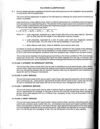
This document is C.M.A.A. Specification No. 70-1983 which provides specifications for electric overhead traveling cranes. It was developed by the Crane Manufacturers Association of America to promote standardization and provide guidelines for equipment selection. The specification contains eight sections covering general specifications, crane service classification, structural design, mechanical design, electrical equipment, inquiry data sheets and speeds, glossary, and index. It is intended to provide technical guidelines but not limit manufacturer ingenuity.
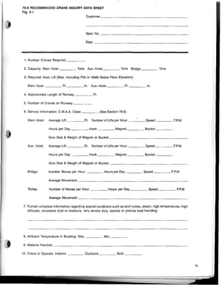
![C.M.A.A. SPECIFICATION NO. 70-1983
SPECIFICATIONS FOR ELECTRIC OVERHEAD TRAVELING CRANES
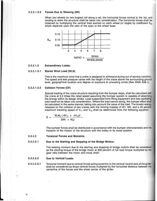
INTRODUCTION
This specification has been developed by the Crane Manufacturers Association
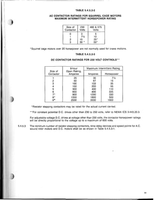
of America, Inc. [C.M.A.A.], an organization of leading electric overhead traveling
crane manufacturers in the United States, for the purpose of promoting standardi-
zation and providing a basis for equipment selection. The use of this specification
should not limit the ingenuity of the individual manufacturer but should provide
guidelines for technical procedure.
In addition to specifications, the pUblication contains information which should
be helpful to the purchasers and users of cranes and to the engineering and archi-
tectural professions. While much of this information must be of a general nature,
the items listed may be checked with individual manufacturers and comparisons
made leading to optimum selection of equipment.
These specifications consist of eight sections, as follows:
70-1. General Specifications.
70-2. Crane Service Classification.
70-3 Structural Design.
70-4. Mechanical Design.
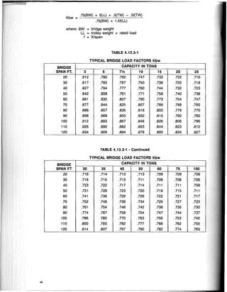
70-5. Electrical Equipment.
70-6. Inquiry Data Sheet and Speeds.
70-7. Glossary.
70-8. Index.
DISCLAIMER'
Users should rely on their own engineers/designers or a manufacturer represen-
tative to specify or design applications or uses. Whenever a user refers to all or
any part of this specification to place an order, mandatory language imposing
requirements in the specification is intended as the user's voluntary acceptance
of those specifications for that order.
The voluntary use of these specifications is not intended to, and does not in any
way, limit the ingenuity or prerogative of individual manufacturers to design or pro-
duce electric overhead traveling cranes which do not comply with these specifica-
tions. Rather, these specifications provide technical guidelines for the user to specify
his application. Following these specifications does not assure compliance with
applicable federal, state, or local regulations and codes which must be referenced
in each instance.
These specifications are not binding on any person and do not have the effect
of law, and CMAA assumes no responsibility and disclaims all liability of any kind,
however arising, as a result of acceptance or use of these specifications.](https://image.slidesharecdn.com/cmaa-specification-70-210127133125/85/Cmaa-specification-70-2-320.jpg)
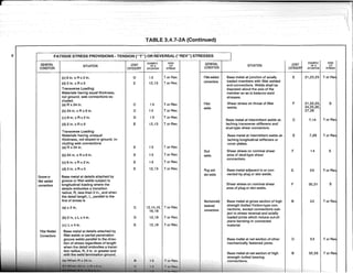
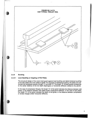
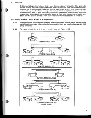
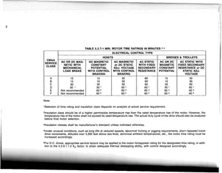
![-----------"------------
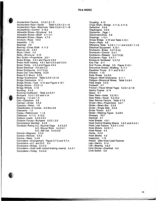
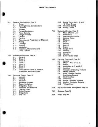
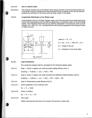
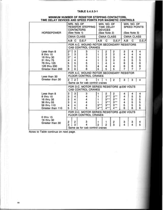
3.4.6 Compression Member
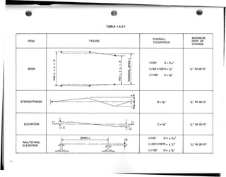
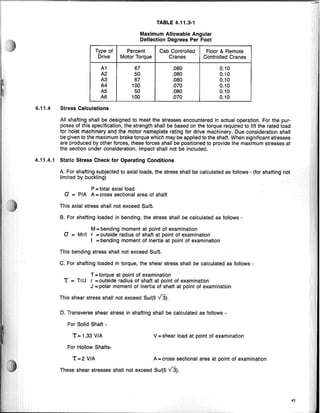
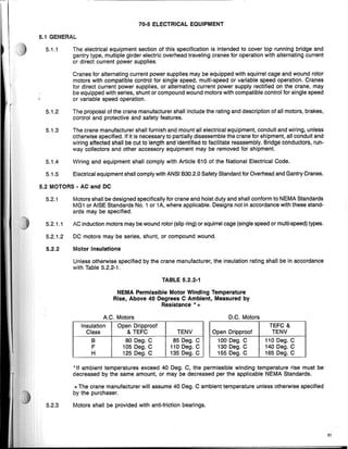
3.4.6.2 On the cross section of axially loaded compression members susceptible to buckling shall
lated when KL/r exceeds Cc:
O.350yp
O.3750yp
0.430yp
ALLOWABLE
SHEAR
STRESS
ALLOWABLE
TENSION
STRESS
] N
ALLOWABLE
COMPRESSION
STRESS*
21I2E
0,
STRESS
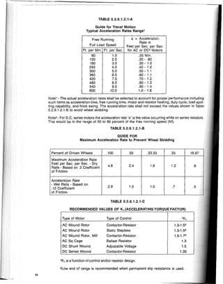
LEVEL
AND CASE
[
(KL/r)2
1 - 2C 2
OA '
[
53 + 3 (KUr)
BC,
where: C, = V
3.4.1 1 O.600yp O.600yp
3.4.2 2 O.660yp O.660yp
3.4.3 3 O.750yp O.750yp
*Not subject to buckling. "See paragraph 3.4.6 and 3.4.B"
The analysis for proving safety against local buckling and lateral and torsional buckling of
plate and local buckling of the rectangular plates forming part of the compression member,
made in accordance with a generally accepted theory of the strength of materials. (See Sectic)h
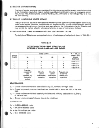
3.4 ALLOWABLE STRESSES
3.4.4 Combined Stresses
12TI2E
aA = -----:c23:c'(c=K"'LI'--:r)~2""N,----
3.4.6.1 The average allowable compression stress on the cross section area of axially loaded compr
members susceptible to buckling shall be calculated when KUr (the largest effective slend
ratio of any segment) is less than Cc:
3.4.4.1 Where state of combined plane stresses exist, the reference stress at can be calculated
following formula:
at =VOx2 + Oy2 - OxOy + 3Txl " aALL.
3.4.4.2 For welds, maximum combined stress Ov shall be calculated as follows:
1 1 r-------
Ov = 2[Ox + Oyl ±2Y (Ox - OyJ2 +4T2 " OALL.
3.4.5 Buckling Analysis
14](https://image.slidesharecdn.com/cmaa-specification-70-210127133125/85/Cmaa-specification-70-16-320.jpg)
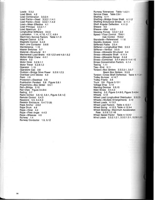
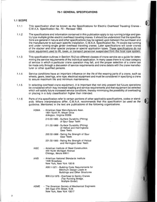
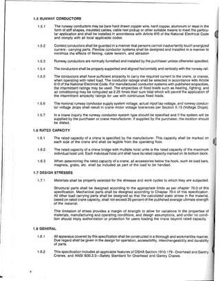
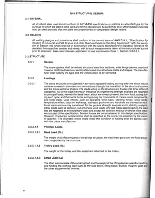
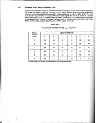
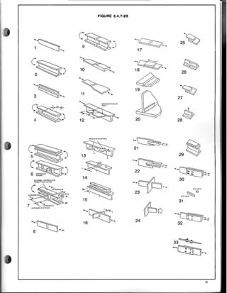
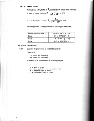
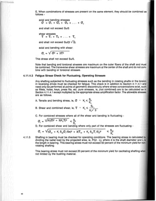
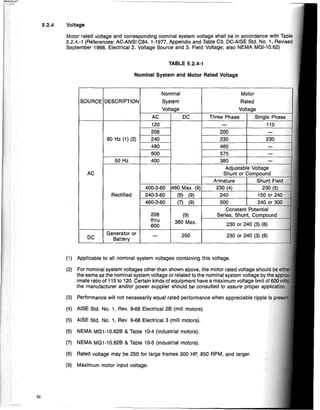
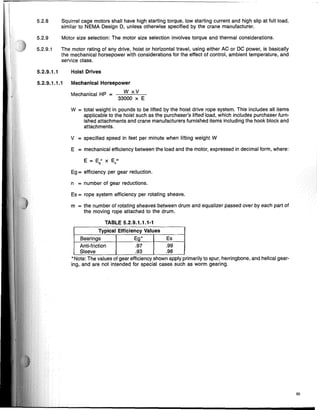
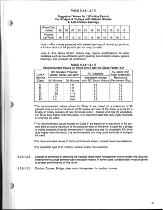
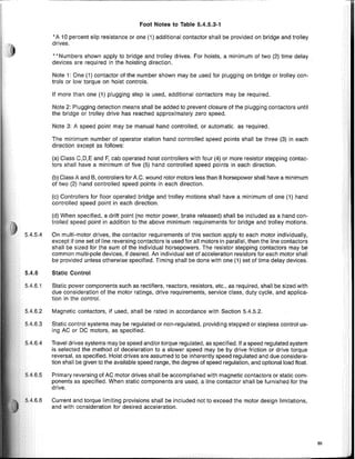
![3.4.6.3 Members subjected to both axial compression and bending stresses shall be nrrlnclClil,h"d
the following requirements:
___
c-",m=-,a--'b""__ + __-,-C-",moc,o-,-b",-y__ <;; 1.0
[1-~]aBX [1 -~]aBY
Oex Oey
~ + ab, + aaby <;;1.0
aBK aBX BY
a,
when aA <;; .15 the following formula may be used
a, ab
, ab
" ~1 0
- - + - - + ~~
aA
aBX
aBy '
where:
K
L
r
E
ay,p
a.
ab
aA
aB
N
N
N
Cmx
Cmy
= effective length factor
= unbraced length of compression member
= radius of gyration of member
= modulus of elasticity
= yield point
= the computed axial stress
= computed compressive bending stress at the point under
consideration
= axial stress that will be permitted if axial force alone existed
= compressive bending stress that will be permitted if bending
moment alone existed
= allowable compression stress from Section 3.4
= __1.:.:2:.;:,1T.:-
2.::E__
23(KUr)2N
= 1.1 Case 1
= 1.0 Case 2
= 0.89 Case 3
a coefficient whose value is taken to be:
1. For compression members in frames subject to joint translation
(sidesway), Cm = 0.85
2. For restrained compression members in frames braced against
joint translation and not sUbject to transverse loading between
their supports in the plane of bending,
M,
Cm = 0.6 - 0.4 M
2
' but not less than 0.4
where M,/M2 is the ratio of the smaller to larger moments at the
ends of that portion of the member unbraced in the plane of bend-
ing under consideration. M,/M2 is positive when the member is
bent in reverse curvature, negative when bent in single curvature.
3. For compression members in frame braced against joint transla-
tion in the plane of loading and sUbjected to transverse loading
between their supports, the value of Cm may be determined by
rational analysis. However, in lieu of such analysis, the following
values may be used:
a. For members whose ends are restrained Cm = 0.85
b. For members whose ends are unrestrained Cm = 1.0
15](https://image.slidesharecdn.com/cmaa-specification-70-210127133125/85/Cmaa-specification-70-17-320.jpg)
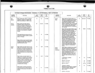
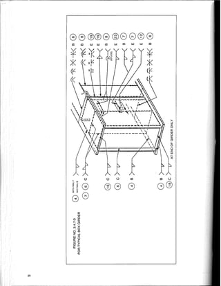
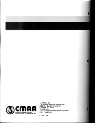
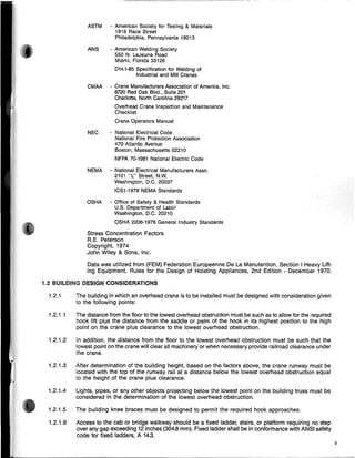
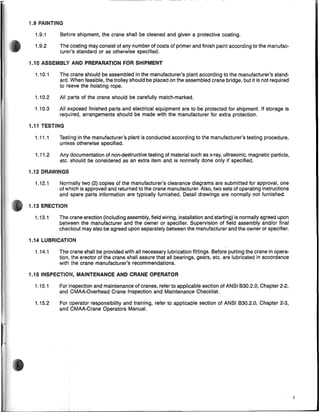
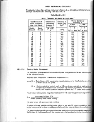
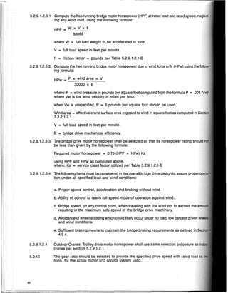
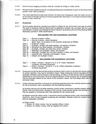
![where:
- type of loading sustained by the plate.
manner in which the plate is supported along the edges
O'kR ~ 0.18360; + 0 ,,"
where: °y ~ yield strength
Op ~ proportional limit (assumed at 0/1.32)
where: Kc ~ buckling coefficient compression
KT ~ buckling coefficient shear
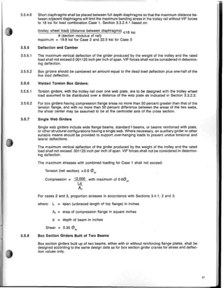
The buckling coefficient Kc and KT are identified for a few simple cases for plates with simply
ported edges in Table 3.4.8.2-1 and depend on:
ratio Q' ~ alb of the two sides of the plate.
b = width of plate (in inches) perpendicular to the compression force
If compression and shear stresses occur simultaneously, the individual critical buckling
and Tk and the calculated stress values°and T are used to determine the critical COll1pal
1t2E [t ]2 [ t]2
0, ~ 12(1-W) b = 26.21 X 10· b
a = actual compression stress
T = actual shear stress
Ok = critical compression stress
Tk = critical shear stress
'I' = stress ratio (see Table No. 3.4.9.2-1)
In the special case where T ~ 0 it is simply 01k ~ Ok and in the special case Wh'''AI
O'k ~ T kV3
If the resulting critical stress is below the proportional limit, buckling is said to be elalmc.
value is above the proportional limit, buckling is said to be inelastic. For inelastic lJUl;~""U
stress shall be reduced to:
0yO,,"
Where: E = modulus of elasticity (for steel E = 29,000,000 PSI)
/A = Poisson's ratio (for steel /A = 0.3)
= thickness of plate (in inches)
It is not the intention of this specification to enter into further details of this problem. For a
detailed and complex analysis such as evaluation of elastically restrained edges, of
and determination of the coefficient of restraint, reference should be made to specialized
0, ~ Euler buckling stress which can be determined from the following formula:
3.4.8.2 Critical buckling stress shall be assumed to be a multiple of the Euler Stress 0,
Ok~ KoO,; Tk~K,O,
22](https://image.slidesharecdn.com/cmaa-specification-70-210127133125/85/Cmaa-specification-70-25-320.jpg)
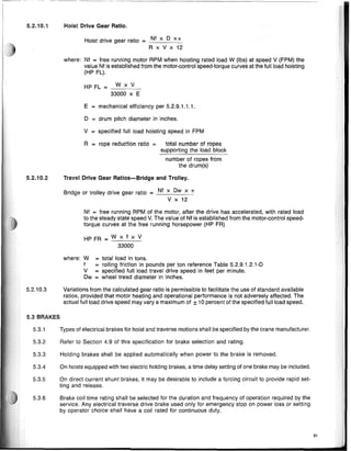
![-~-------~~~
•
Case Loading
Buckling Range of
Buckling Coefficient
Stress Application
1 Compressive stresses, 0, 0, a ;;, 1 8.4
varying as a straight
, Olr Ok = KoO, K(1=
tj1 + 1.1
line.
[ 1 ] 2 [ 2.1 ]
0"tj1"1 tj10,
~a=ab4 tj10, a < 1 KG = a + a (x) tj1 + 1.1
2 Compressive and tensile stresses;
0, 0,
Ko = [(1 + tj1)K'J - (tj1K") + [10tj1 (1 + tj1)]
varying as a straight line and with wherein K' is the
the compression predominating.
"OIf Ok = KoO,
buckling coefficient for tj1 = 0
- 1<tj1<0
(case 1) and K" is the
tj10,
~a=ab~
tj10, buckling coefficient for tj1 = - 1
(case 3).
3 Compressive and tensile stresses, 0, 0,
varying as a straight line, with equal
' OIl Ka = 23.9
edge values, tj1 = -lor with a;;,%
predominantly tensile stresses,
-0, i"a=ab~ -0, Ok = KoO,
a<% 1.87
"tj1<-1
0, 0, KG = 15.87 + ---zy2 + 8.aa2
011
tj10, I+a = ab~ tj10,
4 Uniformly distributed shear stresses. a;;, 1 4.00
KT = 5.34 + ---zy2
+- +T.....- T k = KTO,
to+r a < 1
1-'+ ,I-' .D
.t t -± 5.34
-+T--- ----... KT = 4.00 + ---zy2
~a=ab~
[;l
TABLE NO. 3.4.8.2-1
"For the calculation of a and 0, in case 3 with predominant tension, replace dimension
actual b dimension to determine a and 0, for the simultaneously acting shear
b by 2 x the width of the compression zone. But use](https://image.slidesharecdn.com/cmaa-specification-70-210127133125/85/Cmaa-specification-70-26-320.jpg)
![where:
a = longitudinal distance between full depth diaphragms or transverse stiffeners in inches.
25
[
a [a J2 A a ] .
1
0 = 1.2 0.4 + 0.6 h + 0.9 h + 8 h~t hf3-m4
Longitudinal Stiffeners
When one longitudinal stiffener is used, it should be placed so that its centerline is approximately
0.4 times the distance from the inner surface of the compression flange plate to the neutral axis.
It shall have a moment of inertia no less than:
The moment of inertia need not be greater in any case than as given by the following equation:
I = [22 + 10 3 ~ [1 + ~J ] bf3-ln4
o • • ~ ~
3.5.3.2 For one longitudinal stiffener at the center of the compression plate, where b/2 Is the unsupported
half width between web and stiffener, the moment of inertia of the stiffener shall be no less than:
3.5.3.1 When one, two or three longitudinal stiffeners are added to a plate under uniform compression, divid-
ing it into segments having equal unsupported widths, full edge support will be provided by the longi-
tudinal stiffeners, and the provisions of Section 3.5.2.3 may be applied to the design of the plate material
when stiffeners meet minimum requirements as follows:
[ a [a J2 A a] .
I = 0 6 - + 0 2 - + 3.0 -'- bf3-ln4
o • b . b b2t
A = area of one longitudinal stiffener in square inches.
If Oc is greater than aT a distance equal to twice the distance from the inner surface of the compres-
sion flange to the neutral axis shall be substituted in place of "h" in equation for 1
o.
1
0 = 1.2 [0.3 + 0.4 ~ + 1.3 [~J2 + 14 ~~~ }f3-in4
3.5.2.3 The moment of inertia of longitudinal stiffeners welded to one side of a plate shall be calculated about
the interface of the plate adjacent to the stiffener. For elements of the stiffeners supported along
one edge, the maximum width to thickness ratio shall not be greater than 12.7, and for elements
supported along both edges, the maximum width to thickness ratio shall not be greater than 42.2.
If the ratio of 12.7 is exceeded for the element of the stiffener supported along one edge, but a por-
tion of the stiffener element conforms to the maximum width-thickness ratio and meets the stress
requirements with the excess considered as removed, the member is considered acceptable.
3.5.3 Stiffened Plates in Compression:
3.5.2
3.5.2.1
If Oc is greater than aT a distance equal to twice the distance from the inner surface of the compres-
sion fiange to the neutral axis shall be substituted in place of "h" in equation for 1
o.
3.5.2.2 When two longitudinal stiffeners are used, they should be placed so that their centerlines are ap-
proximately 0.25 and 0.55 times the distance, respectively, from the inner surface of the compres-
sion flange plate to the neutral axis. They shall each have a moment of inertia no less than:](https://image.slidesharecdn.com/cmaa-specification-70-210127133125/85/Cmaa-specification-70-28-320.jpg)
![where:
to = minimum required web thickness - inches
a = 350 t
'IV
a = longitudinal distance between diaphragms or transverse stiffeners - inches
As = area of the stiffener - square inches
t = thickness of the stiffened plate - inches
where: a = longitudinal distance between diaphragms or transverse stiffeners - inches
t = thickness of web in inches
Stiffeners shall be designed to the provisions of Section 3.5.2.3.
Diaphragms and Vertical Stiffeners
The spacing of the vertical web stiffeners in inches shali not exceed the amount given by the
I = 1.2 h3
t0
3
in4
a02
3.5.4
where: aD = required distance between stiffeners - inches
3.5.3.4 For three longitudinal stiffeners, spaced equidistant at the one fourth width locations where
the unsupported width, and limited to alb less than three, the moment of inertia of each of the
stiffeners shall be no less than:
i. = [0.35 ~ + 1.10 [ ~ J2 + 12 ~:~]bt3-in4
3.5.3.3 For two longitudinal stiffeners at the third points of the compression fiange, where bl3 is the un'iUp·
ported width, and A the area of one stiffener, the moment of inertia of each of the two stiffeners
be no less than:
I = [0 4 ~ + 0 8 [~J2 + 80 A,a] bP-in4
• ' b ' b 'b2t
The moment of inertia need not be greater in any case than:
I = [9 + 56 ~ + 90 [~J2 ]bP-in4
• bt bt
3.5.4.1
v = shear stress in web plates (k.s.!.)
Nor should the spacing exceed 72 inches or h, the depth of the web, whichever is greater.
3.5.4.2 Full depth diaphragms may be included as vertical web stiffeners toward meeting this
3.5.4.3 The moment of inertia of any transverse stiffener about the interface of the web plate, if used
absence of diaphragms, shall be no less than:
This moment of inertia does not include additional requirements, if any, for local moments.
elements shall be proportioned to the provisions of Section 3.5.2.3.
3.5.4.4 Web plates shall be suitably reinforced with full depth diaphragms or stiffeners at all major load
3.5.4.5 All diaphragms shall bear against the top cover plate and shall be welded to the web plate
thickness of the diaphragm plate shall be sufficient to resist the trolley wheel load in bearing
allowable bearing stress on the assumption that the wheel load is distributed over a distance
to the width of the rail base pius twice the distance from the rail base to the top of the diaphragm
26](https://image.slidesharecdn.com/cmaa-specification-70-210127133125/85/Cmaa-specification-70-29-320.jpg)
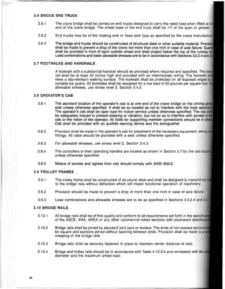
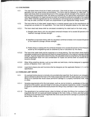
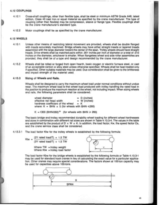
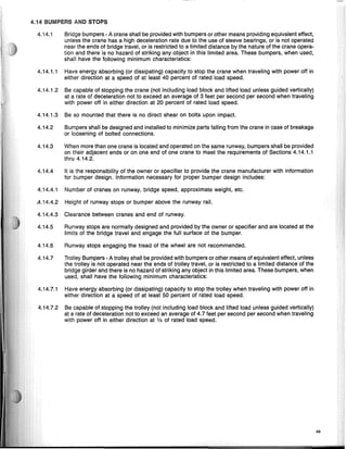
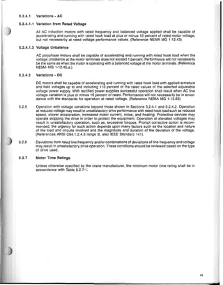
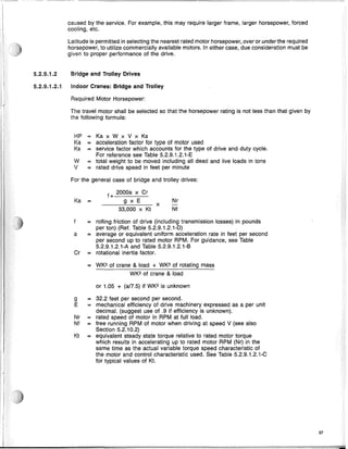

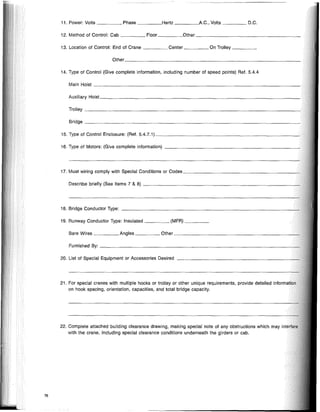
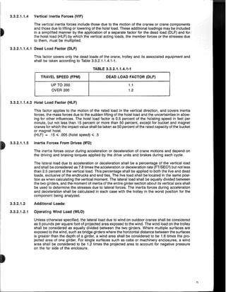
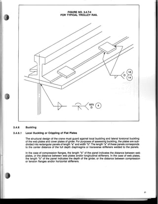
![CLEARANCES: Complete the building drawing below making special note of any obstructions which may
interfere with the crane including special clearance requirements under girders or cab.
77
Pit Floor
F
-I-'-----" -----"
Low point of roof truss, lights,
sprinkler, or other obstructions
Operating
Floor
A (Span-c to c of runway rails)
l
<::
<::
L Idler Girder ("8" Girder)
'" Centerline of Hooks --.
(])
- - - - - I-
,
iii
,
,
>- .- Drive Girder ("A" Girder)
'"
"
<::
oj
" I
~
Walkway-if required
~
Indicate the "North" direction, cab or pendant location, relative locations of
main and auxiliary hook, runway conductor location, adjacent cranes, etc.
P LAN
-'
'0
ill
'0
a:
n
C --L
,
JI+-_IR<;:;r~A;f:(~SFP.::a"n--,c:...:cto:....:c_o"f"r..:u,-n,-w..:a""y_r,,a,-i1.::s),-_--=;:====-:"L E
-r--+-DH:' Rail Size: a r
Cap Channel Size: R +;.1p-,
Runway 8eam Size' S L. . :;::=:L
~
"T Runway /1 L 1
M1
N I
T-~ , U Conductors It11
, Type: P
Obstruction " V
8
1
ELEVATION
A H P
8 Q
C J R
D K S
E L T
F M U
G N V](https://image.slidesharecdn.com/cmaa-specification-70-210127133125/85/Cmaa-specification-70-79-320.jpg)