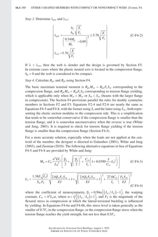
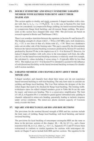
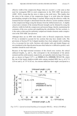
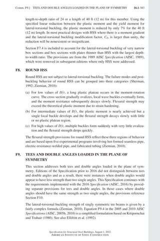
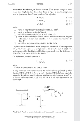
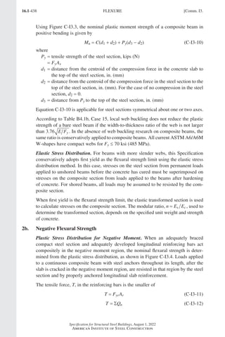
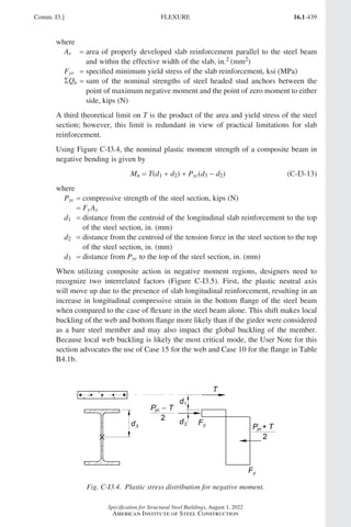
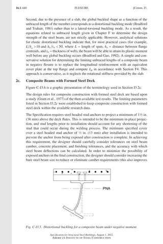
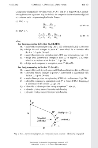
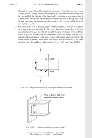
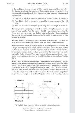
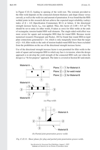
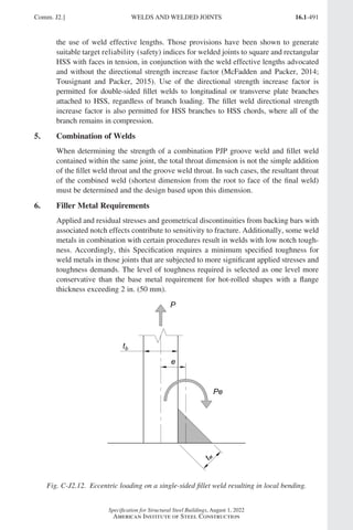
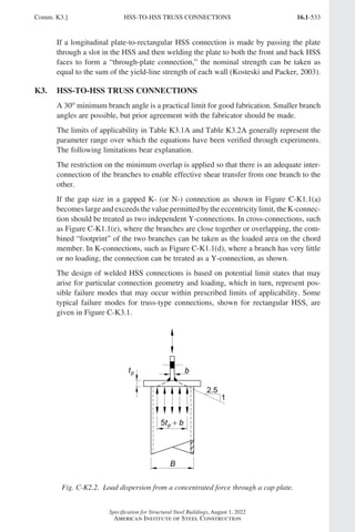
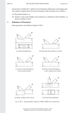
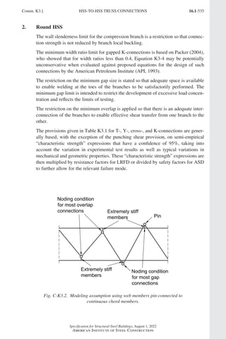
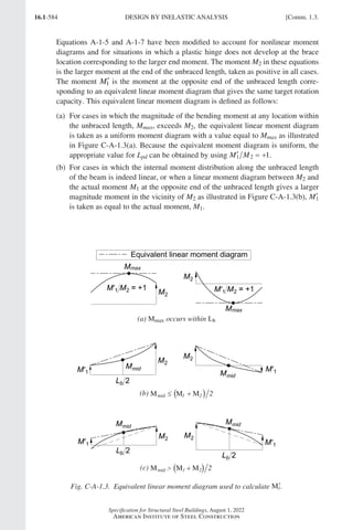
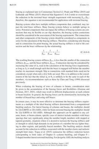
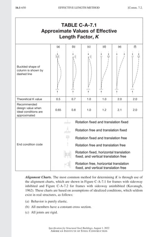
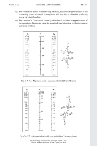
This document is the 2022 edition of the ANSI/AISC 360 Specification for Structural Steel Buildings published by the American Institute of Steel Construction (AISC). It provides requirements for the design of steel-framed buildings and other structures using allowable strength design or load and resistance factor design. This edition supersedes the 2016 version and includes numerous technical modifications and additions. It was developed through a consensus process and approved by AISC's Committee on Specifications.


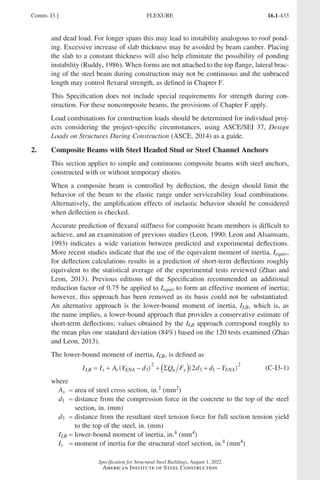
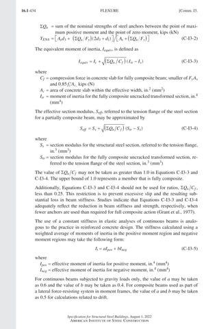
![16.1-3
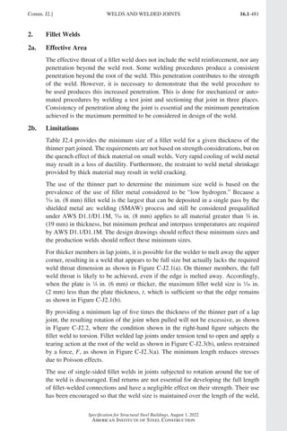
Specification for Structural Steel Buildings, August 1, 2022
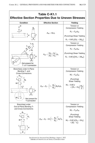
American Institute of Steel Construction
(c) American Iron and Steel Institute (AISI)
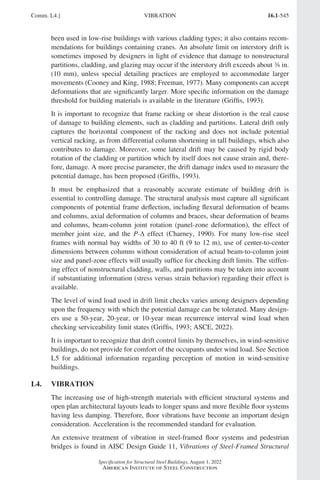
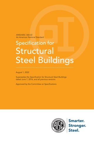
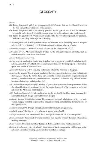
AISI S923-20 Test Standard for Determining the Strength and Stiffness of Shear
Connections of Composite Members
AISI S924-20 Test Standard for Determining the Effective Flexural Stiffness of
Composite Members
(d) American Society of Civil Engineers (ASCE)
ASCE/SEI 7-22 Minimum Design Loads and Associated Criteria for Buildings
and Other Structures
ASCE/SEI/SFPE 29-05 Standard Calculation Methods for Structural Fire
Protection
(e) American Society of Mechanical Engineers (ASME)
ASME B1.1-2019 Unified Inch Screw Threads (UN, UNR, and UNJ Thread
Forms)
ASME B18.2.6-19 Fasteners for Use in Structural Applications
ASME B46.1-19 Surface Texture, Surface Roughness, Waviness, and Lay
(f) American Society for Nondestructive Testing (ASNT)
ANSI/ASNT CP-189-2020 Standard for Qualification and Certification of
Nondestructive Testing Personnel
ASNT SNT-TC-1A-2020 Personnel Qualification and Certification in Nonde-
structive Testing
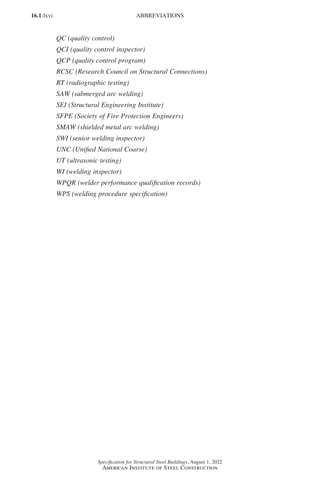
(g) ASTM International (ASTM)
A6/A6M-19 Standard Specification for General Requirements for Rolled Struc-
tural Steel Bars, Plates, Shapes, and Sheet Piling
A36/A36M-19 Standard Specification for Carbon Structural Steel
A53/A53M-20 Standard Specification for Pipe, Steel, Black and Hot-Dipped,
Zinc-Coated, Welded and Seamless
A193/A193M-20 Standard Specification for Alloy-Steel and Stainless Steel
Bolting Materials for High Temperature or High Pressure Service and Other
Special Purpose Applications
A194/A194M-20a Standard Specification for Carbon Steel, Alloy Steel, and
Stainless Steel Nuts for Bolts for High Pressure or High Temperature Service,
or Both
A283/A283M-18 Standard Specification for Low and Intermediate Tensile
Strength Carbon Steel Plates
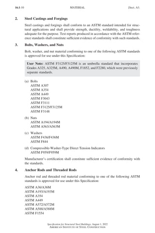
A307-21 Standard Specification for Carbon Steel Bolts, Studs, and Threaded
Rod 60,000 PSI Tensile Strength
User Note: ASTM A325/A325M is included as a grade within ASTM F3125/
F3125M.
A354-17e2 Standard Specification for Quenched and Tempered Alloy Steel
Bolts, Studs, and Other Externally Threaded Fasteners
A370-20 Standard Test Methods and Definitions for Mechanical Testing of Steel
Products
Sect. A2.] REFERENCED SPECIFICATIONS, CODES, AND STANDARDS
Part 16.1 A-F (001-074).indd 3
Part 16.1 A-F (001-074).indd 3 2023-01-10 7:31 PM
2023-01-10 7:31 PM](https://image.slidesharecdn.com/aisc360-22specificationforstructuralsteelbuildings-231108145904-1b416cfe/85/AISC-360-22-Specification-for-Structural-Steel-Buildings-pdf-71-320.jpg)
![16.1-4
Specification for Structural Steel Buildings, August 1, 2022
American Institute of Steel Construction
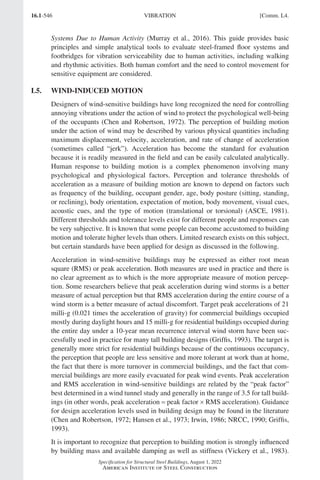
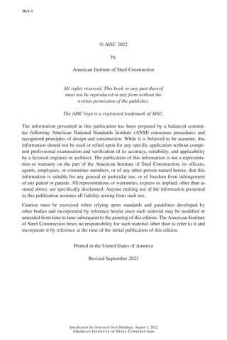
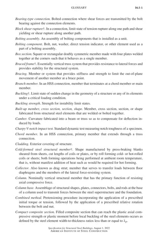
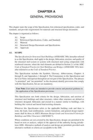
A449-14(2020) Standard Specification for Hex Cap Screws, Bolts and Studs,
Steel, Heat Treated, 120/105/90 ksi Minimum Tensile Strength, General Use
User Note: ASTM A490/A490M is included as a grade within ASTM F3125/
F3125M.
A500/A500M-21 Standard Specification for Cold-Formed Welded and Seamless
Carbon Steel Structural Tubing in Rounds and Shapes
A501/A501M-14 Standard Specification for Hot-Formed Welded and Seamless
Carbon Steel Structural Tubing
A502-03(2015) Standard Specification for Rivets, Steel, Structural
A514/A514M-18e1 Standard Specification for High-Yield-Strength, Quenched
and Tempered Alloy Steel Plate, Suitable for Welding
A529/A529M-19 Standard Specification for High-Strength Carbon-Manganese
Steel of Structural Quality
A563/A563M-21 Standard Specification for Carbon and Alloy Steel Nuts (Inch
and Metric)
A568/A568M-19a Standard Specification for Steel, Sheet, Carbon, Structural,
and High-Strength, Low-Alloy, Hot-Rolled and Cold-Rolled, General Re-
quirements for
A572/A572M-21e1 Standard Specification for High-Strength Low-Alloy Colum-
bium-Vanadium Structural Steel
A588/A588M-19 Standard Specification for High-Strength Low-Alloy Struc-
tural Steel, up to 50 ksi [345 MPa] Minimum Yield Point, with Atmospheric
Corrosion Resistance
A606/A606M-18 Standard Specification for Steel, Sheet and Strip, High-Strength,
Low-Alloy, Hot-Rolled and Cold-Rolled, with Improved Atmospheric Corro-
sion Resistance
A618/A618M-04(2015) Standard Specification for Hot-Formed Welded and
Seamless High-Strength Low-Alloy Structural Tubing
A673/A673M-17 Standard Specification for Sampling Procedure for Impact
Testing of Structural Steel
A709/A709M-18 Standard Specification for Structural Steel for Bridges
A751-20 Standard Test Methods, Practices, and Terminology for Chemical
Analysis of Steel Products
A847/A847M-20 Standard Specification for Cold-Formed Welded and Seamless
High-Strength, Low-Alloy Structural Tubing with Improved Atmospheric
Corrosion Resistance
A913/A913M-19 Standard Specification for High-Strength Low-Alloy Steel
Shapes of Structural Quality, Produced by Quenching and Self-Tempering
Process (QST)
A992/A992M-20 Standard Specification for Structural Steel Shapes
A1011/A1011M-18a Standard Specification for Steel, Sheet and Strip, Hot-Rolled,
Carbon, Structural, High-Strength Low-Alloy, High-Strength Low-Alloy with
Improved Formability, and Ultra-High Strength
A1043/A1043M-18 Standard Specification for Structural Steel with Low Yield
to Tensile Ratio for Use in Buildings
REFERENCED SPECIFICATIONS, CODES, AND STANDARDS [Sect. A2.
Part 16.1 A-F (001-074).indd 4
Part 16.1 A-F (001-074).indd 4 2023-01-10 7:31 PM
2023-01-10 7:31 PM](https://image.slidesharecdn.com/aisc360-22specificationforstructuralsteelbuildings-231108145904-1b416cfe/85/AISC-360-22-Specification-for-Structural-Steel-Buildings-pdf-72-320.jpg)
![16.1-5
Specification for Structural Steel Buildings, August 1, 2022
American Institute of Steel Construction
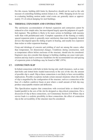
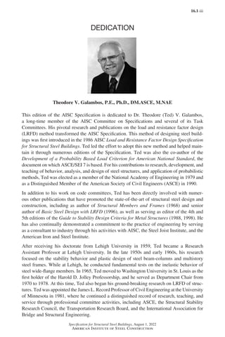
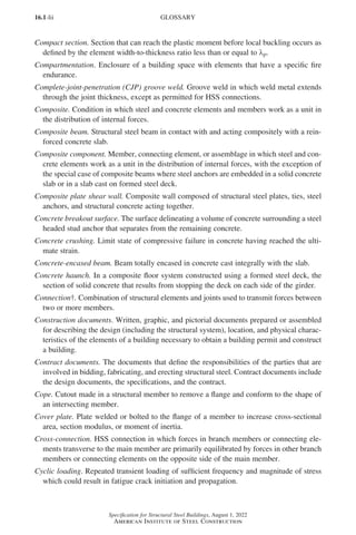
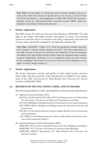
A1065/A1065M-18 Standard Specification for Cold-Formed Electric-Fusion
(Arc) Welded High-Strength Low-Alloy Structural Tubing in Shapes, with 50
ksi [345 MPa] Minimum Yield Point
A1066/A1066M-11(2015)e1 Standard Specification for High-Strength Low-
Alloy Structural Steel Plate Produced by Thermo-Mechanical Controlled
Process (TMCP)
A1085/A1085M-15 Standard Specification for Cold-Formed Welded Carbon
Steel Hollow Structural Sections (HSS)
C567/C567M-19 Standard Test Method for Determining Density of Structural
Lightweight Concrete
E119-20 Standard Test Methods for Fire Tests of Building Construction and
Materials
F436/F436M-19 Standard Specification for Hardened Steel Washers Inch and
Metric Dimensions
F606/F606M-21 Standard Test Methods for Determining the Mechanical
Properties of Externally and Internally Threaded Fasteners, Washers, Direct
Tension Indicators, and Rivets
F844-19 Standard Specification for Washers, Steel, Plain (Flat), Unhardened
for General Use
F959/F959M-17a Standard Specification for Compressible-Washer-Type Direct
Tension Indicators for Use with Structural Fasteners, Inch and Metric Series
F1554-20 Standard Specification for Anchor Bolts, Steel, 36, 55, and 105-ksi
Yield Strength
User Note: ASTM F1554 is the most commonly referenced specification for
anchor rods. Grade and weldability must be specified.
User Note: ASTM F1852 and F2280 are grades within ASTM F3125/F3125M.
F3043-15 Standard Specification for “Twist Off” Type Tension Control Struc-
tural Bolt/Nut/Washer Assemblies, Alloy Steel, Heat Treated, 200 ksi Mini-
mum Tensile Strength
F3111-16 Standard Specification for Heavy Hex Structural Bolt/Nut/Washer
Assemblies, Alloy Steel, Heat Treated, 200 ksi Minimum Tensile Strength
F3125/F3125M-19e2 Standard Specification for High Strength Structural Bolts
and Assemblies, Steel and Alloy Steel, Heat Treated, Inch Dimensions 120 ksi
and 150 ksi Minimum Tensile Strength, and Metric Dimensions 830 MPa and
1040 MPa Minimum Tensile Strength
F3148-17a Standard Specification for High Strength Structural Bolt Assemblies,
Steel and Alloy Steel, Heat Treated, 144 ksi Minimum Tensile Strength, Inch
Dimensions
(h) American Welding Society (AWS)
AWS A5.1/A5.1M:2012 Specification for Carbon Steel Electrodes for Shielded
Metal Arc Welding
AWS A5.5/A5.5M:2014 Specification for Low-Alloy Steel Electrodes for Shielded
Metal Arc Welding
Sect. A2.] REFERENCED SPECIFICATIONS, CODES, AND STANDARDS
Part 16.1 A-F (001-074).indd 5
Part 16.1 A-F (001-074).indd 5 2023-01-10 7:31 PM
2023-01-10 7:31 PM](https://image.slidesharecdn.com/aisc360-22specificationforstructuralsteelbuildings-231108145904-1b416cfe/85/AISC-360-22-Specification-for-Structural-Steel-Buildings-pdf-73-320.jpg)
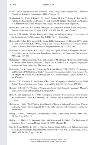
![16.1-7
Specification for Structural Steel Buildings, August 1, 2022
American Institute of Steel Construction
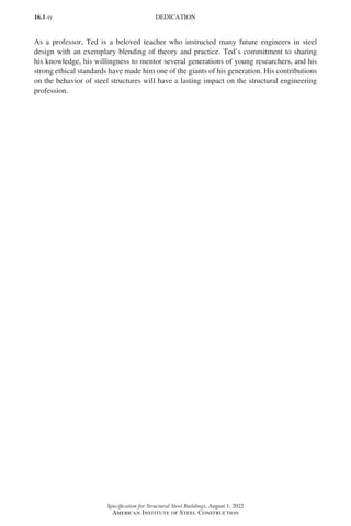
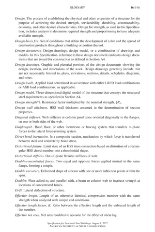
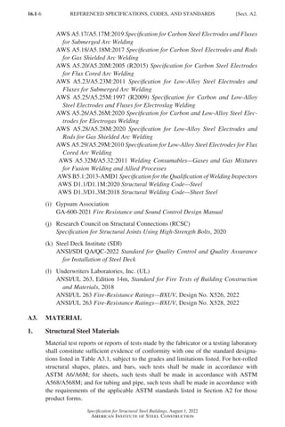
TABLE A3.1
Listed Materials
Standard
Designation
Permissible
Grades/Strengths
Other Limitations
(a) Hot-Rolled Shapes
ASTM A36/A36M − −
ASTM A529/A529M Gr. 50 [345] or Gr. 55 [380] −
ASTM A572/A572M Gr. 42 [290], Gr. 50 [345], Gr. 55 [380],
Gr. 60 [415], or Gr. 65 [450]
Type 1, 2, or 3
ASTM A588/A588M − −
ASTM A709/A709M Gr. 36 [250], Gr. 50 [345], Gr. 50S [345S],
Gr. 50W [345W], QST 50 [QST345],
QST 50S [QST345S], QST 65 [QST450], or
QST 70 [QST485]
−
ASTM A913/A913M Gr. 50 [345], Gr. 60 [415], Gr. 65 [450],
Gr. 70 [485], or Gr. 80 [550]
−
ASTM A992/A992M − −
ASTM A1043/A1043M Gr. 36 [250] or Gr. 50 [345] −
(b) Hollow Structural Sections (HSS)
ASTM A53/A53M Gr. B −
ASTM A500/A500M Gr. B, Gr. C, or Gr. D −
ASTM A501/A501M Gr. B ERW or seamless
ASTM A618/A618M Gr. Ia, Gr. Ib, Gr. II, or Gr. III ERW or seamless
ASTM A847/A847M – –
ASTM A1065/A1065M Gr. 50 [345] or Gr. 50W [345W] A572, A588, or A709
HPS 50W [345W]
ASTM A1085/
A1085M[a]
Gr. A
−
(c) Plates
ASTM A36/A36M − −
ASTM A283/A283M Gr. C or Gr. D −
ASTM A514/A514M – See Note [b].
ASTM A529/A529M Gr. 50 [345] or Gr. 55 [380] –
ASTM A572/A572M Gr. 42 [290], Gr. 50 [345], Gr. 55 [380],
Gr. 60 [415], or Gr. 65 [450]
Type 1, 2, or 3
ASTM A588/A588M − −
ASTM A709/A709M Gr. 36 [250], Gr. 50 [345], Gr. 50W
[345W], HPS 50W [HPS345W], HPS 70W
[HPS485W], or HPS 100W [HPS 690W]
−
−
indicates no restriction applicable on grades/strengths or there are no limitations, as applicable
ERW = electric resistance welded
[a]
ASTM A1085/A1085M material is only available in Grade A, therefore it is permitted to specify ASTM A1085/
A1085M without any grade designation.
[b]
For welded construction, the steel producer shall be contacted for recommendations on minimum and
maximum preheat limits, and minimum and maximum heat input limits.
Sect. A3.] MATERIAL
Part 16.1 A-F (001-074).indd 7
Part 16.1 A-F (001-074).indd 7 2023-01-10 7:31 PM
2023-01-10 7:31 PM](https://image.slidesharecdn.com/aisc360-22specificationforstructuralsteelbuildings-231108145904-1b416cfe/85/AISC-360-22-Specification-for-Structural-Steel-Buildings-pdf-75-320.jpg)
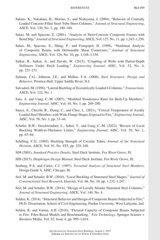
![16.1-8
Specification for Structural Steel Buildings, August 1, 2022
American Institute of Steel Construction
TABLE A3.1 (continued)
Listed Materials
Standard
Designation
Permissible
Grades/Strengths
Other Limitations
(c) Plates (cont’d)
ASTM A1043/A1043M Gr. 36 [250] or Gr. 50 [345] −
ASTM A1066/A1066M Gr. 50 [345], Gr. 60 [415], Gr. 65 [450],
Gr. 70 [485], or Gr. 80 [550]
−
(d) Bars
ASTM A36/A36M – −
ASTM A529/A529M Gr. 50 [345] or Gr. 55 [380] −
ASTM A572/A572M Gr 42 [290], Gr. 50 [345],Gr. 55 [380],
Gr. 60 [415], or Gr. 65 [450]
Type 1, 2, or 3
ASTM A709/A709M Gr. 36 [250], Gr. 50 [345], 50W [345W], or
HPS 50W [HPS345W]
−
(e) Sheet
ASTM A606/A606M Gr. 45 [310] or Gr. 50 [345] Type 2, 4, or 5
ASTM A1011/A1011M Gr. 30 [205] through Gr. 80 [550] SS, HSLAS, HSLAS-F;
all types and classes
−
indicates no restriction applicable on grades/strengths or there are no limitations, as applicable
ERW = electric resistance welded
1a. Listed Materials
Structural steel material conforming to one of the standard designations shown in
Table A3.1 subject to the grades and limitations listed are considered to perform
as anticipated in the other provisions of this Specification and are approved for use
under this Specification.
User Note: Plates, sheets, strips, and bars are different products; however, design
rules do not make a differentiation between these products. The most common
differences among these products are their physical dimensions of width and
thickness.
1b. Other Materials
Materials other than those listed in Table A3.1 are permitted for specific applications
when the suitability of the material is determined to be acceptable by the engineer
of record (EOR).
1c. Unidentified Steel
Unidentified steel, free of injurious defects, is permitted to be used only for members
or details whose failure will not reduce the strength of the structure, either locally or
overall. Such use shall be subject to the approval of the EOR.
MATERIAL [Sect. A3.
Part 16.1 A-F (001-074).indd 8
Part 16.1 A-F (001-074).indd 8 2023-01-10 7:31 PM
2023-01-10 7:31 PM](https://image.slidesharecdn.com/aisc360-22specificationforstructuralsteelbuildings-231108145904-1b416cfe/85/AISC-360-22-Specification-for-Structural-Steel-Buildings-pdf-76-320.jpg)
![16.1-9
Specification for Structural Steel Buildings, August 1, 2022
American Institute of Steel Construction
User Note: Unidentified steel may be used for details where the precise mechani-
cal properties and weldability are not of concern. These are commonly curb
plates, shims, and other similar pieces.
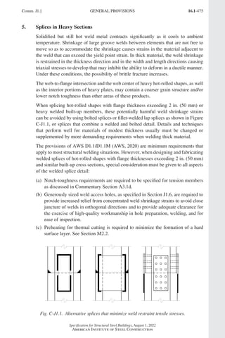
1d. Rolled Heavy Shapes
ASTM A6/A6M hot-rolled shapes with a flange thickness exceeding 2 in. (50 mm)
are considered to be rolled heavy shapes. Rolled heavy shapes used as members sub-
jected to primary (computed) tensile forces due to tension or flexure and spliced or
connected using complete-joint-penetration groove welds that fuse through the thick-
ness of the flange or the flange and the web shall be specified as follows. The structural
design documents shall require that such shapes be supplied with Charpy V-notch
(CVN) impact test results in accordance with ASTM A6/A6M, Supplementary
Requirement S30, Charpy V-Notch Impact Test for Structural Shapes—Alternate
Core Location. The impact test shall meet a minimum average value of 20 ft-lbf (27 J)
absorbed energy at a maximum temperature of +70°F (+21°C).
The requirements in this section do not apply if the splices and connections are made
by bolting. Where a rolled heavy shape is welded to the surface of another shape
using groove welds, the requirements apply only to the shape that has weld metal
fused through the cross section.
User Note: Additional requirements for rolled heavy-shape welded joints are
given in Sections J1.5, J1.6, J2.6, and M2.2.
1e. Built-Up Heavy Shapes
Built-up cross sections consisting of plates with a thickness exceeding 2 in. (50 mm)
are considered built-up heavy shapes. Built-up heavy shapes used as members sub-
jected to primary (computed) tensile forces due to tension or flexure and spliced
or connected to other members using complete-joint-penetration groove welds that
fuse through the thickness of the plates, shall be specified as follows. The structural
design documents shall require that the steel be supplied with Charpy V-notch im-
pact test results in accordance with ASTM A6/A6M, Supplementary Requirement
S5, Charpy V-Notch Impact Test. The impact test shall be conducted in accordance
with ASTM A673/A673M, Frequency P, and shall meet a minimum average value
of 20 ft-lbf (27 J) absorbed energy at a maximum temperature of +70°F (+21°C).
When a built-up heavy shape is welded to the face of another member using groove
welds, these requirements apply only to the shape that has weld metal fused through
the cross section.
User Note: Additional requirements for built-up heavy-shape welded joints are
given in Sections J1.5, J1.6, J2.6, and M2.2.
Sect. A3.] MATERIAL
Part 16.1 A-F (001-074).indd 9
Part 16.1 A-F (001-074).indd 9 2023-01-10 7:31 PM
2023-01-10 7:31 PM](https://image.slidesharecdn.com/aisc360-22specificationforstructuralsteelbuildings-231108145904-1b416cfe/85/AISC-360-22-Specification-for-Structural-Steel-Buildings-pdf-77-320.jpg)
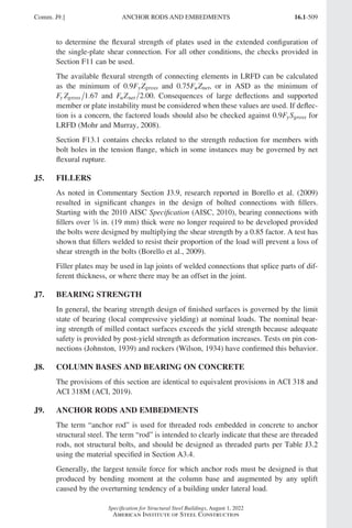
![16.1-11
Specification for Structural Steel Buildings, August 1, 2022
American Institute of Steel Construction
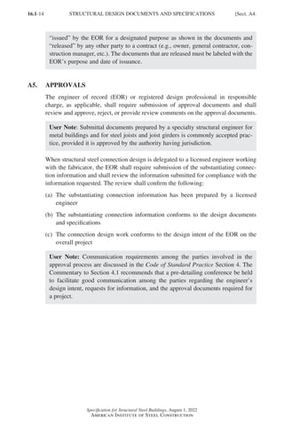
User Note: ASTM F1554 is the preferred material specification for anchor rods.
ASTM A449 material is permitted for high-strength anchor rods and threaded rods
of any diameter.
Threads on anchor rods and threaded rods shall conform to Class 2A, Unified Coarse
Thread Series of ASME B1.1, except for anchor rods over 1 in. (25 mm) diameter
which are permitted to conform to Class 2A, 8UN Thread Series.
Manufacturer’s certification shall constitute sufficient evidence of conformity with
the standards.
5. Consumables for Welding
Filler metals and fluxes shall conform to one of the following specifications of the
American Welding Society:
AWS A5.1/A5.1M
AWS A5.5/A5.5M
AWS A5.17/A5.17M
AWS A5.18/A5.18M
AWS A5.20/A5.20M
AWS A5.23/A5.23M
AWS A5.25/A5.25M
AWS A5.26/A5.26M
AWS A5.28/A5.28M
AWS A5.29/A5.29M
AWS A5.32M/A5.32
Manufacturer’s certification shall constitute sufficient evidence of conformity with
the standards.
6. Headed Stud Anchors
Steel headed stud anchors shall conform to the requirements of the Structural
Welding Code—Steel (AWS D1.1/D1.1M).
Manufacturer’s certification shall constitute sufficient evidence of conformity with
AWS D1.1/D1.1M.
A4. STRUCTURAL DESIGN DOCUMENTS AND SPECIFICATIONS
Structural design documents and specifications issued for construction of all or a
portion of the work shall be clearly legible and drawn to an identified scale that is
appropriate to clearly convey the information.
1. Structural Design Documents and Specifications Issued for Construction
Structural design documents and specifications shall be based on the consideration
of the design loads, forces, and deformations to be resisted by the structural frame
in the completed project and give the following information, as applicable, to define
the scope of the work to be fabricated and erected:
Sect. A4.] STRUCTURAL DESIGN DOCUMENTS AND SPECIFICATIONS
Part 16.1 A-F (001-074).indd 11
Part 16.1 A-F (001-074).indd 11 2023-01-10 7:31 PM
2023-01-10 7:31 PM](https://image.slidesharecdn.com/aisc360-22specificationforstructuralsteelbuildings-231108145904-1b416cfe/85/AISC-360-22-Specification-for-Structural-Steel-Buildings-pdf-79-320.jpg)
![16.1-13
Specification for Structural Steel Buildings, August 1, 2022
American Institute of Steel Construction
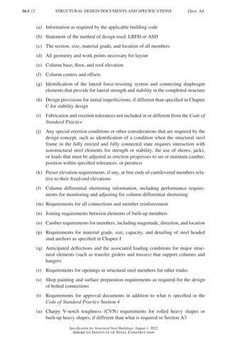
(v) Identification of members and joints subjected to fatigue
(w)
Identification of members and joints requiring nondestructive testing in addition
to what is required in Chapter N
(x)
Additional project requirements, as deemed appropriate by the engineer of
record (EOR), that impact the life safety of the structure
User Note: According to the Code of Standard Practice Section 3, it is permitted
in the structural design documents and specifications to refer to architectural,
electrical, and/or mechanical design documents for some information as required
in this section.
When structural steel connection design is delegated, the design documents and
specifications shall include the following:
(a) Design requirements for the delegated design
(b) Requirements for substantiating connection information
User Note: For projects that require consideration of seismic provisions, addi-
tional requirements for information to be shown on the structural design
documents and specifications are contained in Section A4 of the AISC Seismic
Provisions for Structural Steel Buildings. For safety-related steel structures for
nuclear facilities, additional requirements for information to be shown are con-
tained in ANSI/AISC N690, Section NA4.
User Note: The intent of the information required to be shown on design docu-
ments issued for construction as identified in Section A4 is to ensure that these
items are documented and addressed by the EOR prior to construction. Some
information may be contained in deferred submittals prepared by a specialty
structural engineer and approved by the registered design professional in
responsible charge. Additional information regarding design documents and
submittals pertaining to metal buildings and steel joists can be found in the
Common Industry Practices published by the Metal Building Manufacturers
Association (MBMA) and the Code of Standard Practice for Steel Joists and
Joist Girders published by the Steel Joist Institute (SJI), respectively. Steel
(open-web) joists and steel joist girders are not structural steel per the Code
of Standard Practice Section 2.2 and therefore fall outside the scope of this
Specification.
2. Structural Design Documents and Specifications Issued for Any Purpose
Structural design documents and specifications shall be clearly identified by the EOR
with the intended purpose and date of issuance before being released by any party for
the purpose of bidding or as the basis for a contract.
User Note: The terminology now used in this Specification and the Code of
Standard Practice is that structural design documents and specifications are
Sect. A4.] STRUCTURAL DESIGN DOCUMENTS AND SPECIFICATIONS
Part 16.1 A-F (001-074).indd 13
Part 16.1 A-F (001-074).indd 13 2023-01-11 9:14 AM
2023-01-11 9:14 AM](https://image.slidesharecdn.com/aisc360-22specificationforstructuralsteelbuildings-231108145904-1b416cfe/85/AISC-360-22-Specification-for-Structural-Steel-Buildings-pdf-81-320.jpg)
![16.1-17
Specification for Structural Steel Buildings, August 1, 2022
American Institute of Steel Construction
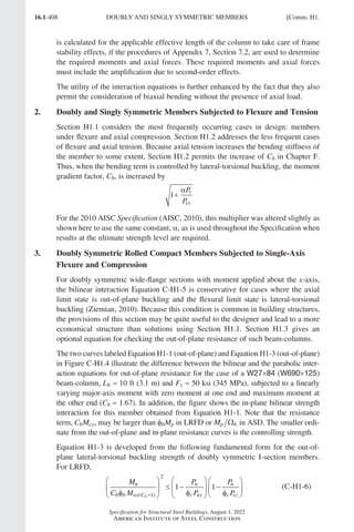
4. Design of Connections and Supports
Connection elements shall be designed in accordance with the provisions of Chapters
J and K. The forces and deformations used in design of the connections shall be
consistent with the intended performance of the connection and the assumptions used
in the design of the structure. Self-limiting inelastic deformations of the connections
are permitted.
At points of support, beams, girders, and trusses shall be restrained against rotation
about their longitudinal axis unless it can be shown by analysis that the restraint is
not required.
User Note: Code of Standard Practice Section 3.1.2 addresses communication of
necessary information for the design of connections.
4a. Simple Connections
A simple connection transmits a negligible moment. In the analysis of the structure,
simple connections may be assumed to allow unrestrained relative rotation between
the framing elements being connected. A simple connection shall have sufficient
rotation capacity to accommodate the required rotation determined by the analysis
of the structure.
4b. Moment Connections
Two types of moment connections, fully restrained and partially restrained, are per-
mitted, as specified below.
(a) Fully restrained (FR) moment connections
A fully restrained (FR) moment connection transfers moment with a negligible
rotation between the connected members. In the analysis of the structure, the
connection may be assumed to allow no relative rotation. An FR connection
shall have sufficient strength and stiffness to maintain the initial angle between
the connected members at the strength limit states.
(b) Partially restrained (PR) moment connections
Partially restrained (PR) moment connections transfer moments, but the relative
rotation between connected members is not negligible. In the analysis of the struc-
ture, the moment-rotation response characteristics of any PR connection shall be
included. The response characteristics of the PR connection shall be based on
the technical literature or established by analytical or experimental means. The
component elements of a PR connection shall have sufficient strength, stiffness,
and deformation capacity such that the moment-rotation response can be realized
up to and including the required strength of the connection.
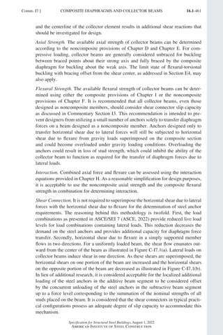
5. Design of Diaphragms and Collectors
Diaphragms and collectors shall be designed for forces that result from loads, as
stipulated in Section B2. They shall be designed in conformance with the provisions
of Chapters C through K, as applicable.
Sect. B3.] DESIGN BASIS
Part 16.1 A-F (001-074).indd 17
Part 16.1 A-F (001-074).indd 17 2023-01-10 7:31 PM
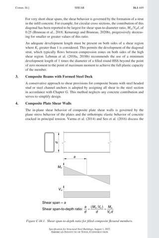
2023-01-10 7:31 PM](https://image.slidesharecdn.com/aisc360-22specificationforstructuralsteelbuildings-231108145904-1b416cfe/85/AISC-360-22-Specification-for-Structural-Steel-Buildings-pdf-85-320.jpg)
![16.1-19
Specification for Structural Steel Buildings, August 1, 2022
American Institute of Steel Construction
The nominal strength and resistance or safety factors for the applicable limit states
are specified in Chapters D through K.
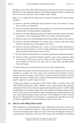
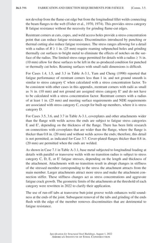
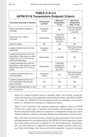
11. Design for Fatigue
Design of members and their connections shall consider fatigue in accordance with
Appendix 3. Fatigue need not be considered for seismic effects or for the effects of
wind loading on typical building lateral force-resisting systems and building enclo-
sure components.
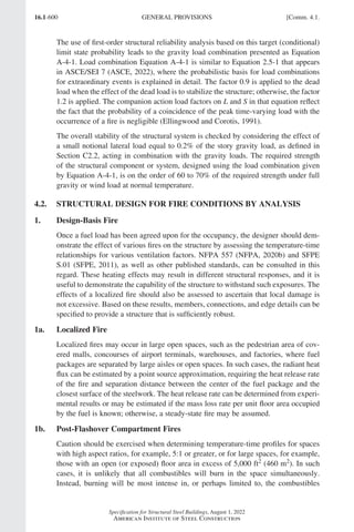
12. Design for Fire Conditions
Design for fire conditions shall satisfy the requirements stipulated in Appendix 4.
Two methods of design for fire conditions are provided in Appendix 4: (a) by
analysis and (b) by qualification testing. Compliance with the fire-protection require-
ments in the applicable building code shall be deemed to satisfy the requirements of
Appendix 4.
User Note: Design by qualification testing is the prescriptive method specified
in most building codes. Traditionally, on most projects where the architect is
the prime professional, the architect has been the responsible party to specify
and coordinate fire protection requirements. Design by analysis is a newer engi-
neering approach to fire protection. Designation of the person(s) responsible for
designing for fire conditions is a contractual matter to be addressed on each proj-
ect. This section is not intended to create or imply a contractual requirement for
the engineer of record responsible for the structural design or any other member
of the design team.
13. Design for Corrosion Effects
Where corrosion could impair the strength or serviceability of a structure, structural
components shall be designed to tolerate corrosion or shall be protected against
corrosion.
B4. MEMBER PROPERTIES
1. Classification of Sections for Local Buckling
For members subjected to axial compression, sections are classified as nonslender-
element or slender-element sections. For a nonslender-element section, the width-to-
thickness ratios of its compression elements shall not exceed λr from Table B4.1a.
If the width-to-thickness ratio of any compression element exceeds λr, the section is
a slender-element section.
For members subjected to flexure, sections are classified as compact, noncompact, or
slender-element sections. For all sections addressed in Table B4.1b, flanges must be
continuously connected to the web or webs. For a section to qualify as compact, the
width-to-thickness ratios of its compression elements shall not exceed the limiting
width-to-thickness ratios, λp, from Table B4.1b. If the width-to-thickness ratio of
Sect. B4.] MEMBER PROPERTIES
Part 16.1 A-F (001-074).indd 19
Part 16.1 A-F (001-074).indd 19 2023-01-10 7:31 PM
2023-01-10 7:31 PM](https://image.slidesharecdn.com/aisc360-22specificationforstructuralsteelbuildings-231108145904-1b416cfe/85/AISC-360-22-Specification-for-Structural-Steel-Buildings-pdf-87-320.jpg)
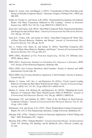
![16.1-21
Specification for Structural Steel Buildings, August 1, 2022
American Institute of Steel Construction
TABLE B4.1a
Width-to-Thickness Ratios: Compression Elements
Members Subjected to Axial Compression
Case
Description of Element
Width-to-
Thickness
Ratio
Limiting
Width-to-
Thickness Ratio
λ
λr (nonslender/
slender) Examples
Unstiffened
Elements
1 (1)
Flanges of rolled I-shaped
sections
(2)
Plates projecting from
rolled I-shaped sections
(3)
Outstanding legs of pairs
of angles connected with
continuous contact
(4)
Flanges of channels
(5)
Flanges of tees
b t 0 56
.
E
Fy
2 (1)
Flanges of built-up
I-shaped sections
(2)
Plates or angle legs
projecting from built-up
I-shaped sections
b t
[a]
0 64
.
k E
F
c
y
3 (1)
Legs of single angles
(2)
Legs of double angles
with separators
(3)
All other unstiffened
elements
b t 0 45
.
E
Fy
4 Stems of tees
d t 0 75
.
E
Fy
Stiffened
Elements
5 Webs of doubly symmetric
rolled and built-up I-shaped
sections and channels h tw 1 49
.
E
Fy
6 Walls of rectangular HSS
b t 1 40
.
E
Fy
7 Flange cover plates between
lines of fasteners or welds
b t 1 40
.
E
Fy
8 All other stiffened elements
b t 1 49
.
E
Fy
9 Round HSS
D t 0 11
.
E
Fy
E = modulus of elasticity of steel = 29,000 ksi (200 000 MPa)
Fy = specified minimum yield stress, ksi (MPa)
[a] k h t
c w
= 4 , but shall not be taken as less than 0.35 nor greater than 0.76 for calculation purposes.
Sect. B4.] MEMBER PROPERTIES
Part 16.1 A-F (001-074).indd 21
Part 16.1 A-F (001-074).indd 21 2023-01-10 7:31 PM
2023-01-10 7:31 PM](https://image.slidesharecdn.com/aisc360-22specificationforstructuralsteelbuildings-231108145904-1b416cfe/85/AISC-360-22-Specification-for-Structural-Steel-Buildings-pdf-89-320.jpg)
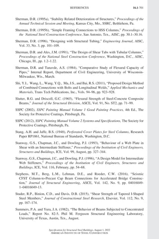
![16.1-22
Specification for Structural Steel Buildings, August 1, 2022
American Institute of Steel Construction
TABLE B4.1b
Width-to-Thickness Ratios: Compression Elements
Members Subjected to Flexure
Case
Description of
Element
Width-to-
Thickness
Ratio
Limiting
Width-to-Thickness
Ratio
Examples
λ
λp
(compact/
noncom-
pact)
λ
λr
(non-
compact/
slender)
Unstiffened
Elements
10 (1)
Flanges of
rolled I-shaped
sections
(2)
Flanges of
channels
(3) Flanges of tees
b t 0 38
.
E
Fy
1 0
.
E
Fy
11 Flanges of doubly
and singly
symmetric
I-shaped built-up
sections
b t 0 38
.
E
Fy
[a] [b]
0 95
.
k E
F
c
L
12 Legs of single
angles b t 0 54
.
E
Fy
0 91
.
E
Fy
13 Flanges of all
I-shaped sections
and channels in
flexure about the
minor axis
b t 0 38
.
E
Fy
1 0
.
E
Fy
14 Stems of tees
d t 0 84
.
E
Fy
1 52
.
E
Fy
(d)
For flanges of rectangular hollow structural sections (HSS), the width, b, is the
clear distance between webs less the inside corner radius on each side. For webs
of rectangular HSS, h is the clear distance between the flanges less the inside
corner radius on each side. If the corner radius is not known, b and h shall be
taken as the corresponding outside dimension minus three times the thickness.
The thickness, t, shall be taken as the design wall thickness, per Section B4.2.
(e)
For flanges or webs of box sections and other stiffened elements, the width, b, is
the clear distance between the elements providing stiffening.
(f)
For perforated cover plates, b is the transverse distance between the nearest line
of fasteners, and the net area of the plate is taken at the widest hole.
(g)
For round hollow structural sections (HSS), the width shall be taken as the out-
side diameter, D, and the thickness, t, shall be taken as the design wall thickness,
as defined in Section B4.2.
MEMBER PROPERTIES [Sect. B4.
Part 16.1 A-F (001-074).indd 22
Part 16.1 A-F (001-074).indd 22 2023-01-29 12:33 PM
2023-01-29 12:33 PM](https://image.slidesharecdn.com/aisc360-22specificationforstructuralsteelbuildings-231108145904-1b416cfe/85/AISC-360-22-Specification-for-Structural-Steel-Buildings-pdf-90-320.jpg)
![16.1-23
Specification for Structural Steel Buildings, August 1, 2022
American Institute of Steel Construction
TABLE B4.1b (continued)
Width-to-Thickness Ratios: Compression Elements
Members Subjected to Flexure
Case
Description
of Element
Width-to-
Thickness
Ratio
Limiting
Width-to-Thickness Ratio
Examples
λ
λp
(compact/
noncompact)
λ
λr
(non-
compact/
slender)
Stiffened
Elements
15 Webs of
doubly
symmetric
I-shaped
sections and
channels
h tw 3 76
.
E
Fy
5 70
.
E
Fy
16 Webs of singly
symmetric
I-shaped
sections
hc tw
[c]
h
h
E
F
M
M
c
p y
p
y
r
0 54 0 09
2
. .
−
≤ λ
5 70
.
E
Fy
17 Flanges of
rectangular
HSS b t 1 12
.
E
Fy
1 40
.
E
Fy
18 Flange cover
plates between
lines of
fasteners or
welds
b t 1 12
.
E
Fy
1 40
.
E
Fy
19 Webs of
rectangular
HSS and box
sections
h t 2 42
.
E
Fy
5 70
.
E
Fy
20 Round HSS
D t 0 07
.
E
Fy
0 31
.
E
Fy
21 Flanges of box
sections
b t 1 12
.
E
Fy
1 49
.
E
Fy
[a]
kc h tw
= 4 but shall not be taken as less than 0.35 nor greater than 0.76 for calculation purposes.
[b]
F F
L y
= 7
0. for slender web I-shaped members and major-axis bending of compact and noncompact web
built-up I-shaped members with S S
xt xc ≥ 0.7; and F F S S F
L y x xc y
= ≥
t 5
0. for major-axis bending of
compact and noncompact web built-up I-shaped members with S S
xt xc 0.7, where S , S
xc xt = elastic
section modulus referred to compression and tension flanges, respectively, in.3 (mm3)
[c]
My is the moment at yielding of the extreme fiber, kip-in. (N-mm); Mp = Fy Zx, plastic moment, kip-in.
(N-mm), where Zx = plastic section modulus taken about the x-axis, in.3 (mm3)
ENA = elastic neutral axis
PNA = plastic neutral axis
Sect. B4.] MEMBER PROPERTIES
Part 16.1 A-F (001-074).indd 23
Part 16.1 A-F (001-074).indd 23 2023-01-10 7:31 PM
2023-01-10 7:31 PM](https://image.slidesharecdn.com/aisc360-22specificationforstructuralsteelbuildings-231108145904-1b416cfe/85/AISC-360-22-Specification-for-Structural-Steel-Buildings-pdf-91-320.jpg)
![16.1-25
Specification for Structural Steel Buildings, August 1, 2022
American Institute of Steel Construction
In determining the net area across plug or slot welds, the weld metal shall not be
considered as adding to the net area.
For members without holes, the net area, An, is equal to the gross area, Ag.
B5. FABRICATION AND ERECTION
Fabrication, shop painting, and erection shall satisfy the requirements stipulated in
Chapter M.
User Note: Code of Standard Practice Section 4 addresses requirements for fab-
rication and erection documents and Section 4.4 addresses the approval process
for approval documents.
B6. QUALITY CONTROL AND QUALITY ASSURANCE
Quality control and quality assurance activities shall satisfy the requirements stipu-
lated in Chapter N.
B7. EVALUATION OF EXISTING STRUCTURES
The evaluation of existing structures shall satisfy the requirements stipulated in
Appendix 5.
B8. DIMENSIONAL TOLERANCES
The provisions in this Specification are based on the assumption that dimensional
tolerances provided in the Code of Standard Practice and in the ASTM standards
provided in Section A3.1a are satisfied. Where larger tolerances are permitted, the
effects of such tolerances shall be considered.
Sect. B8.] DIMENSIONAL TOLERANCES
Part 16.1 A-F (001-074).indd 25
Part 16.1 A-F (001-074).indd 25 2023-01-10 7:31 PM
2023-01-10 7:31 PM](https://image.slidesharecdn.com/aisc360-22specificationforstructuralsteelbuildings-231108145904-1b416cfe/85/AISC-360-22-Specification-for-Structural-Steel-Buildings-pdf-93-320.jpg)
![16.1-27
Specification for Structural Steel Buildings, August 1, 2022
American Institute of Steel Construction
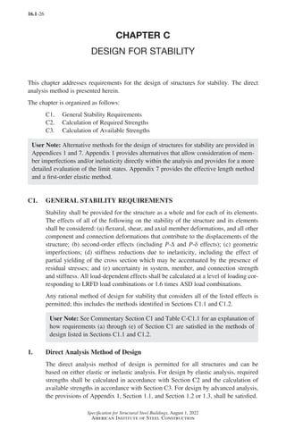
2. Alternative Methods of Design
The effective length method and the first-order analysis method, both defined in
Appendix 7, are based on elastic analysis and are permitted as alternatives to the
direct analysis method for structures that satisfy the limitations specified in that
appendix.
C2. CALCULATION OF REQUIRED STRENGTHS
For the direct analysis method of design, the required strengths of components of the
structure shall be determined from an elastic analysis conforming to Section C2.1.
The analysis shall include consideration of initial imperfections in accordance with
Section C2.2 and adjustments to stiffness in accordance with Section C2.3.
1. General Analysis Requirements
The analysis of the structure shall conform to the following requirements:
(a)
The analysis shall consider flexural, shear, and axial member deformations, and
all other component and connection deformations that contribute to displace-
ments of the structure. The analysis shall incorporate reductions in all stiffnesses
that are considered to contribute to the stability of the structure, as specified in
Section C2.3.
(b)
The analysis shall be a second-order analysis that considers both P-Δ and P-δ
effects, except that it is permissible to neglect the effect of P-δ on the response
of the structure when the following conditions are satisfied: (1) the structure
supports gravity loads primarily through nominally vertical columns, walls, or
frames; (2) the ratio of maximum second-order drift to maximum first-order drift
(both determined for LRFD load combinations or 1.6 times ASD load combina-
tions, with stiffnesses adjusted as specified in Section C2.3) in all stories is equal
to or less than 1.7; and (3) no more than one-third of the total gravity load on the
structure is supported by columns that are part of moment-resisting frames in the
direction of translation being considered. It is necessary in all cases to consider
P-δ effects in the evaluation of individual members subjected to compression
and flexure.
User Note: A P-Δ-only second-order analysis (one that neglects the effects
of P-δ on the response of the structure) is permitted under the conditions
listed. In this case, the requirement for considering P-δ effects in the evalu-
ation of individual members can be satisfied by applying the B1 multiplier
defined in Appendix 8, Section 8.1.2, to the required flexural strength of the
member.
Use of the approximate method of second-order analysis provided in Appendix
8, Section 8.1, is permitted.
(c)
The analysis shall consider all gravity and other applied loads that may influence
the stability of the structure.
Sect. C2.] CALCULATION OF REQUIRED STRENGTHS
Part 16.1 A-F (001-074).indd 27
Part 16.1 A-F (001-074).indd 27 2023-01-10 7:31 PM
2023-01-10 7:31 PM](https://image.slidesharecdn.com/aisc360-22specificationforstructuralsteelbuildings-231108145904-1b416cfe/85/AISC-360-22-Specification-for-Structural-Steel-Buildings-pdf-95-320.jpg)
![16.1-29
Specification for Structural Steel Buildings, August 1, 2022
American Institute of Steel Construction
initial system imperfections in the analysis for gravity-only load combinations and
not in the analysis for load combinations that include applied lateral loads.
2b. Use of Notional Loads to Represent Imperfections
For structures that support gravity loads primarily through nominally vertical col-
umns, walls, or frames, it is permissible to use notional loads to represent the effects
of initial system imperfections in the position of points of intersection of members in
accordance with the requirements of this section. The notional load shall be applied
to a model of the structure based on its nominal geometry.
User Note: In general, the notional load concept is applicable to all types of
structures and to imperfections in the positions of both points of intersection of
members and points along members, but the specific requirements in Sections
C2.2b(a) through C2.2b(d) are applicable only for the particular class of structure
and type of system imperfection identified here.
(a)
Notional loads shall be applied as lateral loads at all levels. The notional loads
shall be additive to other lateral loads and shall be applied in all load combina-
tions, except as indicated in Section C2.2b(d). The magnitude of the notional
loads shall be
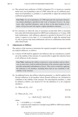
Ni = 0.002αYi (C2-1)
where
α = 1.0 (LRFD); α = 1.6 (ASD)
Ni = notional load applied at level i, kips (N)
Yi =
gravity load applied at level i from the LRFD load combination or ASD
load combination, as applicable, kips (N)
User Note: The use of notional loads can lead to additional (generally small)
fictitious base shears in the structure. The correct horizontal reactions at the
foundation may be obtained by applying an additional horizontal force at the
base of the structure, equal and opposite in direction to the sum of all notional
loads, distributed among vertical load-carrying elements in the same propor-
tion as the gravity load supported by those elements. The notional loads can
also lead to additional overturning effects, which are not fictitious.
(b)
The notional load at any level, Ni, shall be distributed over that level in the same
manner as the gravity load at the level. The notional loads shall be applied in the
direction that provides the greatest destabilizing effect.
User Note: For most building structures, the requirement regarding notional
load direction may be satisfied as follows: for load combinations that do not
include lateral loading, consider two alternative orthogonal directions of
notional load application, in a positive and a negative sense in each of the
two directions, in the same direction at all levels; for load combinations that
include lateral loading, apply all notional loads in the direction of the resul-
tant of all lateral loads in the combination.
Sect. C2.] CALCULATION OF REQUIRED STRENGTHS
Part 16.1 A-F (001-074).indd 29
Part 16.1 A-F (001-074).indd 29 2023-01-10 7:31 PM
2023-01-10 7:31 PM](https://image.slidesharecdn.com/aisc360-22specificationforstructuralsteelbuildings-231108145904-1b416cfe/85/AISC-360-22-Specification-for-Structural-Steel-Buildings-pdf-97-320.jpg)
![16.1-31
Specification for Structural Steel Buildings, August 1, 2022
American Institute of Steel Construction
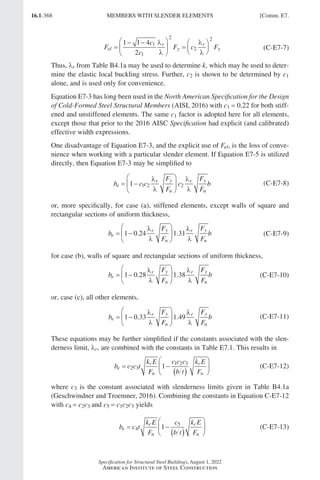
Pns =
cross-section compressive strength; for nonslender-element sections,
Pns = FyAg, and for slender-element sections, Pns = FyAe, where Ae is as
defined in Section E7 with Fn = Fy, kips (N)
User Note: Taken together, Sections (a) and (b) require the use of 0.8τb times
the nominal elastic flexural stiffness and 0.8 times other nominal elastic stiff-
nesses for structural steel members in the analysis.
(c)
In structures to which Section C2.2b is applicable, in lieu of using τb 1.0, where
αP P
r ns 0.5, it is permissible to use τb = 1.0 for all noncomposite members if a
notional load of 0 00
. 1αYi [where Yi is as defined in Section C2.2b(a)] is applied
at all levels, in the direction specified in Section C2.2b(b), in all load combina-
tions. These notional loads shall be added to those, if any, used to account for
the effects of initial imperfections in the position of points of intersection of
members and shall not be subject to the provisions of Section C2.2b(d).
(d)
Where components composed of materials other than structural steel are consid-
ered to contribute to the stability of the structure, and the governing codes and
specifications for the other materials require greater reductions in stiffness, such
greater stiffness reductions shall be applied to those components.
C3. CALCULATION OF AVAILABLE STRENGTHS
For the direct analysis method of design, the available strengths of members and con-
nections shall be calculated in accordance with the provisions of Chapters D through
K, as applicable, with no further consideration of overall structure stability. The
effective length for flexural buckling of all members shall be taken as the unbraced
length unless a smaller value is justified by rational analysis.
Bracing intended to define the unbraced lengths of members shall have sufficient
stiffness and strength to control member movement at the braced points.
User Note: Methods of satisfying this bracing requirement are provided in
Appendix 6. The requirements of Appendix 6 are not applicable to bracing that is
included in the design of the lateral force-resisting system of the overall structure.
Sect. C3.] CALCULATION OF AVAILABLE STRENGTHS
Part 16.1 A-F (001-074).indd 31
Part 16.1 A-F (001-074).indd 31 2023-01-10 7:31 PM
2023-01-10 7:31 PM](https://image.slidesharecdn.com/aisc360-22specificationforstructuralsteelbuildings-231108145904-1b416cfe/85/AISC-360-22-Specification-for-Structural-Steel-Buildings-pdf-99-320.jpg)
![16.1-33
Specification for Structural Steel Buildings, August 1, 2022
American Institute of Steel Construction
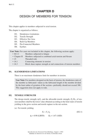
(b) For tensile rupture
P F A
n u e
= (D2-2)
φt = 0.75 (LRFD) Ωt = 2.00 (ASD)
where
Ae = effective net area, in.2 (mm2)
Ag = gross area of member, in.2 (mm2)
Fy = specified minimum yield stress, ksi (MPa)
Fu = specified minimum tensile strength, ksi (MPa)
Where connections use plug, slot, or fillet welds in holes or slots, the effective net
area through the holes shall be used in Equation D2-2.
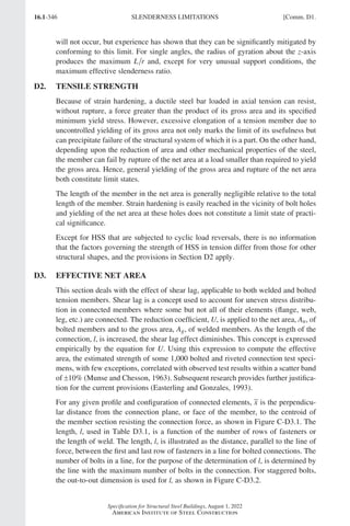
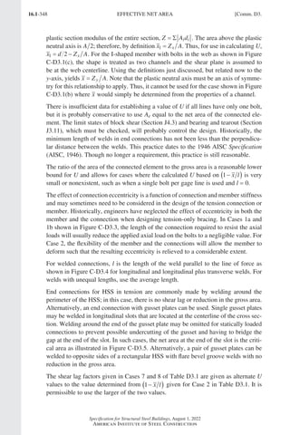
D3. EFFECTIVE NET AREA
The gross area, Ag, and net area, An, of tension members shall be determined in
accordance with the provisions of Section B4.3.
The effective net area of tension members shall be determined as
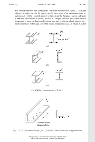
Ae = AnU (D3-1)
where U, the shear lag factor, is determined as shown in Table D3.1.
For open cross sections such as W, M, S, C, or HP shapes, WTs, STs, and single and
double angles, the shear lag factor, U, need not be less than the ratio of the gross area
of the connected element(s) to the member gross area. This provision does not apply
to closed sections, such as HSS, nor to plates.
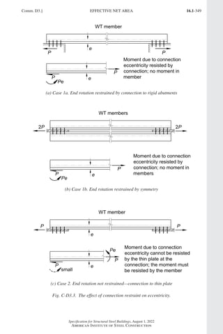
D4. BUILT-UP MEMBERS
For limitations on the longitudinal spacing of connectors between elements in con-
tinuous contact consisting of a plate and a shape, or two plates, see Section J3.6.
Lacing, perforated cover plates, or tie plates without lacing are permitted to be used
on the open sides of built-up tension members. Tie plates shall have a length not
less than two-thirds the distance between the lines of welds or fasteners connecting
them to the components of the member. The thickness of such tie plates shall not be
less than one-fiftieth of the distance between these lines. The longitudinal spacing of
intermittent welds or fasteners at tie plates shall not exceed 6 in. (150 mm).
User Note: The longitudinal spacing of connectors between components should
preferably limit the slenderness ratio in any component between the connectors
to 300.
Sect. D4.] BUILT-UP MEMBERS
Part 16.1 A-F (001-074).indd 33
Part 16.1 A-F (001-074).indd 33 2023-01-10 7:31 PM
2023-01-10 7:31 PM](https://image.slidesharecdn.com/aisc360-22specificationforstructuralsteelbuildings-231108145904-1b416cfe/85/AISC-360-22-Specification-for-Structural-Steel-Buildings-pdf-101-320.jpg)
![16.1-34
Specification for Structural Steel Buildings, August 1, 2022
American Institute of Steel Construction
TABLE D3.1
Shear Lag Factors for Connections
to Tension Members
Case Description of Element Shear Lag Factor, U Examples
1 All tension members where the tension
load is transmitted directly to each of the
cross-sectional elements by fasteners or
welds (except as in Cases 4, 5, and 6).
U = 1.0 –
2 All tension members, except HSS, where
the tension load is transmitted to some
but not all of the cross-sectional elements
by fasteners or by longitudinal welds
in combination with transverse welds.
Alternatively, Case 7 is permitted for W, M,
S, and HP shapes and Case 8 is permitted
for angles.
U
x
= −
1
l
x
x
x
x
3 All tension members where the tension
load is transmitted only by transverse
welds to some but not all of the cross-
sectional elements.
U = 1.0 and
An = area of the
directly connected
elements
–
4[a] Plates, angles, channels with welds
at heels, tees, and W-shapes with
connected elements, where the tension
load is transmitted by longitudinal welds
only. See Case 2 for definition of x.
U
w
x
=
+
−
3
3
1
2
2 2
l
l l
5 Round and rectangular HSS with single
concentric gusset through slots in the
HSS.
x
R
t
U
x
l
p
= −
= +
−
sin
.
θ
θ
θ
1
2
1
3 2 10
in rad
x
x b
b tH t
H b t
U
x
l
= −
+ −
+ −
= −
2 2
2 4 4
1
2 2 x
6 Rectangular HSS with two side gusset
plates. U
BU HU
H B
U
B
U
H
B H
B
H
=
+
+
=
+
=
+
3
3
3
3
2
2 2
2
2 2
l
l
l
l
B = overall width of rectangular HSS member, measured 90° to the plane of the connection, in. (mm);
D = outside diameter of round HSS, in. (mm); H = overall height of rectangular HSS member, measured in the
plane of the connection, in. (mm); d = depth of section, in. (mm); for tees, d = depth of the section from which
the tee was cut, in. (mm); l = length of connection, in. (mm); w = width of plate, in. (mm); x = eccentricity of
connection, in. (mm).
[a]
l
l l
=
+
1 2
2
, where l1 and l2 shall not be less than 4 times the weld size.
BUILT-UP MEMBERS [Sect. D4.
Part 16.1 A-F (001-074).indd 34
Part 16.1 A-F (001-074).indd 34 2023-01-11 9:19 AM
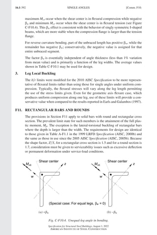
2023-01-11 9:19 AM](https://image.slidesharecdn.com/aisc360-22specificationforstructuralsteelbuildings-231108145904-1b416cfe/85/AISC-360-22-Specification-for-Structural-Steel-Buildings-pdf-102-320.jpg)
![16.1-35
Specification for Structural Steel Buildings, August 1, 2022
American Institute of Steel Construction
TABLE D3.1 (continued)
Shear Lag Factors for Connections
to Tension Members
Case Description of Element Shear Lag Factor, U Examples
7 W-, M-, S-, or HP-shapes,
or tees cut from these
shapes. (If U is calculated
per Case 2, the larger
value is permitted to be
used.)
with flange connected
with three or more
fasteners per line in the
direction of loading
b d U
f ≥ =
2
3
0 0
, .9
b d U
f =
2
3
0 85
, .
–
with web connected
with four or more
fasteners per line in the
direction of loading
U = 0.70 –
8 Single and double angles.
(If U is calculated per
Case 2, the larger value
is permitted to be used.)
with four or more
fasteners per line in the
direction of loading
U = 0.80 –
with three fasteners per
line in the direction of
loading (with fewer than
three fasteners per line
in the direction of
loading, use Case 2)
U = 0.60 –
B = overall width of rectangular HSS member, measured 90° to the plane of the connection, in. (mm);
D = outside diameter of round HSS, in. (mm); H = overall height of rectangular HSS member, measured in the
plane of the connection, in. (mm); d = depth of section, in. (mm); for tees, d = depth of the section from which
the tee was cut, in. (mm); l = length of connection, in. (mm); w = width of plate, in. (mm); x = eccentricity of
connection, in. (mm).
[a]
l
l l
=
+
1 2
2
, where l1 and l2 shall not be less than 4 times the weld size.
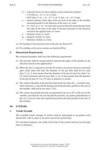
D5. PIN-CONNECTED MEMBERS
1. Tensile Strength
The design tensile strength, φtPn, and the allowable tensile strength, Pn t
Ω , of pin-
connected members, shall be the lower value determined according to the limit states
of tensile rupture, shear rupture, bearing, and yielding.
(a) For tensile rupture
P F tb
n u e
( )
= 2 (D5-1)
φt = 0.75 (LRFD) Wt = 2.00 (ASD)
(b) For shear rupture
P C F A
n r u sf
.
= 0 6 (D5-2)
φsf = 0.75 (LRFD) Wsf = 2.00 (ASD)
where
Asf = 2t a d
+
( )
2
=
area on the shear failure path, in.2 (mm2)
Sect. D5.] PIN-CONNECTED MEMBERS
Part 16.1 A-F (001-074).indd 35
Part 16.1 A-F (001-074).indd 35 2023-01-10 7:31 PM
2023-01-10 7:31 PM](https://image.slidesharecdn.com/aisc360-22specificationforstructuralsteelbuildings-231108145904-1b416cfe/85/AISC-360-22-Specification-for-Structural-Steel-Buildings-pdf-103-320.jpg)
![16.1-37
Specification for Structural Steel Buildings, August 1, 2022
American Institute of Steel Construction
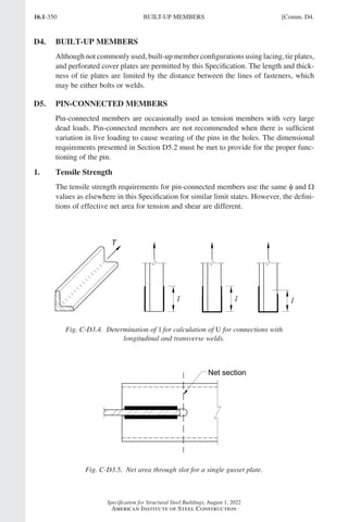
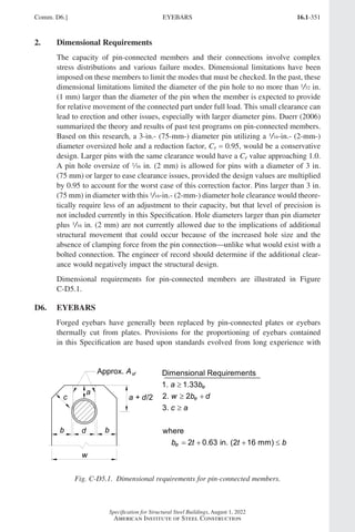
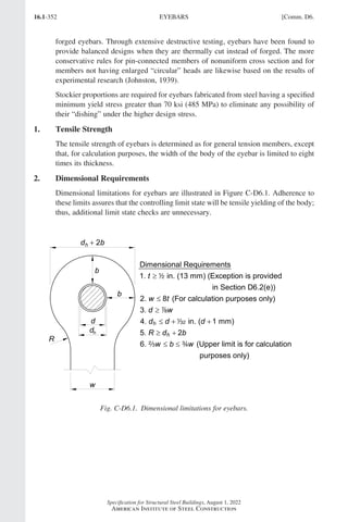
2. Dimensional Requirements
Eyebars shall meet the following requirements:
(a)
Eyebars shall be of uniform thickness, without reinforcement at the pin holes,
and have circular heads with the periphery concentric with the pin hole.
(b)
The radius of transition between the circular head and the eyebar body shall not
be less than the head diameter.
(c)
The pin diameter shall not be less than seven-eighths times the eyebar body
width, and the pin-hole diameter shall not be more than 32 in. (1 mm) greater
than the pin diameter.
(d)
For steels having Fy greater than 70 ksi (485 MPa), the hole diameter shall not
exceed five times the plate thickness, and the width of the eyebar body shall be
reduced accordingly.
(e)
A thickness of less than 2 in. (13 mm) is permissible only if external nuts are
provided to tighten pin plates and filler plates into snug contact.
(f)
The width from the hole edge to the plate edge perpendicular to the direction of
applied load shall be greater than two-thirds and, for the purpose of calculation,
not more than three-fourths times the eyebar body width.
Sect. D6.] EYEBARS
Part 16.1 A-F (001-074).indd 37
Part 16.1 A-F (001-074).indd 37 2023-01-10 7:31 PM
2023-01-10 7:31 PM](https://image.slidesharecdn.com/aisc360-22specificationforstructuralsteelbuildings-231108145904-1b416cfe/85/AISC-360-22-Specification-for-Structural-Steel-Buildings-pdf-105-320.jpg)
![16.1-39
Specification for Structural Steel Buildings, August 1, 2022
American Institute of Steel Construction
TABLE USER NOTE E1.1
Selection Table for the Application of
Chapter E Sections
Cross Section
Without Slender
Elements
With Slender
Elements
Sections in
Chapter E
Limit States
Sections in
Chapter E
Limit
States
E3
E4
FB
TB
E7 LB
FB
TB
E3
E4
FB
FTB
E7 LB
FB
FTB
E3 FB E7 LB
FB
E3 FB E7 LB
FB
E3
E4
FB
FTB
E7 LB
FB
FTB
E6
E3
E4
FB
FTB
E6
E7 LB
FB
FTB
E3
E4
E5
FB
FTB
E5
E7 LB
FB
E3 FB NA NA
Unsymmetrical shapes other
than single angles
E4 FTB E7 LB
FTB
FB = flexural buckling; FTB = flexural-torsional buckling; LB = local buckling; TB = torsional buckling; NA =
not applicable
Sect. E1.] GENERAL PROVISIONS
Part 16.1 A-F (001-074).indd 39
Part 16.1 A-F (001-074).indd 39 2023-01-10 7:31 PM
2023-01-10 7:31 PM](https://image.slidesharecdn.com/aisc360-22specificationforstructuralsteelbuildings-231108145904-1b416cfe/85/AISC-360-22-Specification-for-Structural-Steel-Buildings-pdf-107-320.jpg)
![16.1-41
Specification for Structural Steel Buildings, August 1, 2022
American Institute of Steel Construction
where
Ag = gross area of member, in.2 (mm2)
E = modulus of elasticity of steel, ksi (MPa)
=
29,000 ksi (200 000 MPa)
Fe =
elastic buckling stress determined according to Equation E3-4; or as specified
in Appendix 7, Section 7.2.3(b); or through an elastic buckling analysis, as
applicable, ksi (MPa)
=
π2
2
E
L
r
c
(E3-4)
Fy = specified minimum yield stress of the type of steel being used, ksi (MPa)
r = radius of gyration, in. (mm)
User Note: The two inequalities for calculating the limits of applicability of
Sections E3(a) and E3(b), one based on L r
c and one based on F F
y e, provide
the same result for flexural buckling.
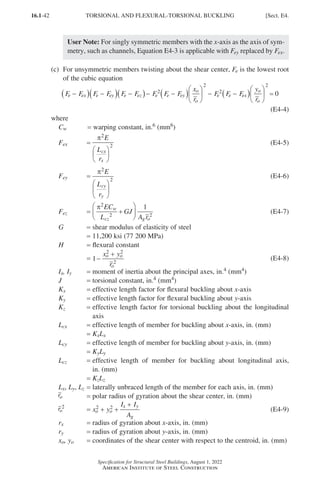
E4.
TORSIONAL AND FLEXURAL-TORSIONAL BUCKLING OF SINGLE
ANGLES AND MEMBERS WITHOUT SLENDER ELEMENTS
This section applies to singly symmetric and unsymmetric members, certain doubly
symmetric members, such as cruciform or built-up members, and doubly symmetric
members when the torsional unbraced length exceeds the lateral unbraced length,
all without slender elements. These provisions also apply to single angles with
b t E Fy
0 71
. , where b is the width of the longest leg and t is the thickness.
The nominal compressive strength, Pn, shall be determined based on the limit states
of torsional and flexural-torsional buckling:
P F A
n n g
= (E4-1)
The nominal stress, Fn, shall be determined according to Equation E3-2 or E3-3,
using the torsional or flexural-torsional elastic buckling stress, Fe, determined as
follows:
(a) For doubly symmetric members twisting about the shear center
F
EC
L
GJ
I I
e
w
cz x y
= +
+
π2
2
1
(E4-2)
(b)
For singly symmetric members twisting about the shear center where y is the axis
of symmetry
F
F F
H
F F H
F F
e
ey ez ey ez
ey ez
=
+
− −
+
2
1 1
4
2
( )
(E4-3)
Sect. E4.] TORSIONAL AND FLEXURAL-TORSIONAL BUCKLING
Part 16.1 A-F (001-074).indd 41
Part 16.1 A-F (001-074).indd 41 2023-01-10 7:31 PM
2023-01-10 7:31 PM](https://image.slidesharecdn.com/aisc360-22specificationforstructuralsteelbuildings-231108145904-1b416cfe/85/AISC-360-22-Specification-for-Structural-Steel-Buildings-pdf-109-320.jpg)
![16.1-43
Specification for Structural Steel Buildings, August 1, 2022
American Institute of Steel Construction
User Note: For doubly symmetric I-shaped sections, Cw may be taken as
I h
y o
2
4, where ho is the distance between flange centroids, in lieu of a more
precise analysis. For tees and double angles, the term with Cw may be omitted
when computing Fez.
(d)
For doubly symmetric I-shaped members with minor-axis lateral bracing offset
from the shear center
F
EI
L
h
y GJ
A r
e
y
cz
o
a
g o
= +
+
π2
2
2
2
2
4
1
(E4-10)
where
ho = distance between flange centroids, in. (mm)
ro
2 = r r y x
x y a a
2 2 2 2
+ + + (E4-11)
xa = bracing offset distance along x-axis = 0
ya = bracing offset distance along y-axis, in. (mm)
(e)
For doubly symmetric I-shaped members with major-axis lateral bracing offset
from the shear center
F
EI
L
h I
I
x GJ
A r
e
y
cz
o x
y
a
g o
= +
+
π2
2
2
2
2
4
1
(E4-12)
where
ro
2 = r r y x
x y a a
2 2 2 2
+ + + (E4-11)
xa = bracing offset distance along x-axis, in. (mm)
ya = bracing offset distance along y-axis = 0
(f)
For all other members with lateral bracing offset from the shear center, the elas-
tic buckling stress, Fe, shall be determined by analysis.
User Note: Bracing offset from the shear center is often referred to as con-
strained-axis torsional buckling and is discussed further in the Commentary.
Members that buckle in this mode will exhibit twisting because the braces
restrain only lateral movement.
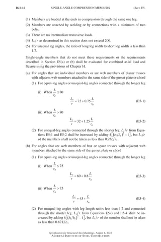
E5. SINGLE-ANGLE COMPRESSION MEMBERS
The nominal compressive strength, Pn, of single-angle members shall be the lowest
value based on the limit states of flexural buckling in accordance with Section E3 or
Section E7, as applicable, or flexural-torsional buckling in accordance with Section
E4. Flexural-torsional buckling need not be considered when b t E Fy
≤ 0 71
. .
The effects of eccentricity on single-angle members are permitted to be neglected
and the member evaluated as axially loaded using one of the effective slenderness
ratios specified in Section E5(a) or E5(b), provided that the following requirements
are met:
Sect. E5.] SINGLE-ANGLE COMPRESSION MEMBERS
Part 16.1 A-F (001-074).indd 43
Part 16.1 A-F (001-074).indd 43 2023-01-10 7:31 PM
2023-01-10 7:31 PM](https://image.slidesharecdn.com/aisc360-22specificationforstructuralsteelbuildings-231108145904-1b416cfe/85/AISC-360-22-Specification-for-Structural-Steel-Buildings-pdf-111-320.jpg)
![16.1-45
Specification for Structural Steel Buildings, August 1, 2022
American Institute of Steel Construction
where
L = length of member between work points at truss chord centerlines, in. (mm)
Lc = effective length of the member for buckling about the minor axis, in. (mm)
bl = length of longer leg of angle, in. (mm)
bs = length of shorter leg of angle, in. (mm)
ra =
radius of gyration about the geometric axis parallel to the connected leg,
in. (mm)
rz = radius of gyration about the minor principal axis, in. (mm)
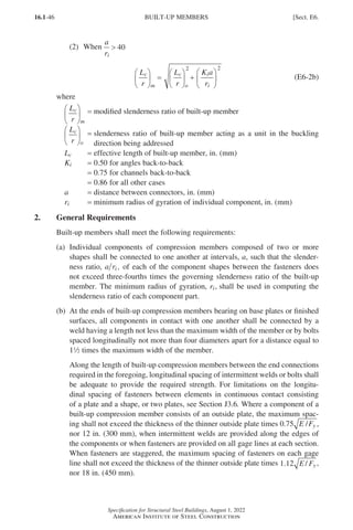
E6. BUILT-UP MEMBERS
1. Compressive Strength
This section applies to built-up members composed of two shapes either (a) inter-
connected by bolts or welds or (b) with at least one open side interconnected by
perforated cover plates or lacing with tie plates. The end connection shall be welded
or connected by means of pretensioned bolts with Class A or B faying surfaces.
User Note: It is acceptable to design a bolted end connection of a built-up com-
pression member for the full compressive load with bolts in bearing and bolt
design based on the shear strength; however, the bolts must be pretensioned. In
built-up compression members, such as double-angle struts in trusses, a small
relative slip between the elements can significantly reduce the compressive
strength of the strut. Therefore, the connection between the elements at the ends
of built-up members should be designed to resist slip.
The nominal compressive strength of built-up members composed of two shapes that
are interconnected by bolts or welds shall be determined in accordance with Sections
E3, E4, or E7, subject to the following modification. In lieu of more accurate analy-
sis, if the buckling mode involves relative deformations that produce shear forces in
the connectors between individual shapes, L r
c is replaced by L r
c m
( ) , determined
as follows:
(a) For intermediate connectors that are bolted snug-tight
L
r
L
r
a
r
c
m
c
o i
=
+
2 2
(E6-1)
(b)
For intermediate connectors that are welded or are connected by means of pre-
tensioned bolts with Class A or B faying surfaces
(1) When
a
ri
≤ 40
L
r
L
r
c
m
c
o
=
(E6-2a)
Sect. E6.] BUILT-UP MEMBERS
Part 16.1 A-F (001-074).indd 45
Part 16.1 A-F (001-074).indd 45 2023-01-29 11:50 AM
2023-01-29 11:50 AM](https://image.slidesharecdn.com/aisc360-22specificationforstructuralsteelbuildings-231108145904-1b416cfe/85/AISC-360-22-Specification-for-Structural-Steel-Buildings-pdf-113-320.jpg)
![16.1-47
Specification for Structural Steel Buildings, August 1, 2022
American Institute of Steel Construction
(c)
Open sides of compression members built up from plates or shapes shall be
provided with continuous cover plates perforated with a succession of access
openings. The unsupported width of such plates at access openings, as defined
in Section B4.1, is assumed to contribute to the available strength provided the
following requirements are met:
(1)
The width-to-thickness ratio shall conform to the limitations of Section
B4.1.
User Note: It is conservative to use the limiting width-to-thickness ratio
for Case 7 in Table B4.1a with the width, b, taken as the transverse dis-
tance between the nearest lines of fasteners. The net area of the plate is
taken at the widest hole. In lieu of this approach, the limiting width-to-
thickness ratio may be determined through analysis.
(2)
The ratio of length (in direction of stress) to width of hole shall not ex-
ceed 2.
(3)
The clear distance between holes in the direction of stress shall be not less
than the transverse distance between nearest lines of connecting fasteners or
welds.
(4)
The periphery of the holes at all points shall have a minimum radius of
12 in. (38 mm).
(d)
As an alternative to perforated cover plates, lacing with tie plates is permitted at
each end and at intermediate points if the lacing is interrupted. Tie plates shall
be as near the ends as practicable. In members providing available strength, the
end tie plates shall have a length of not less than the distance between the lines of
fasteners or welds connecting them to the components of the member.
Intermediate tie plates shall have a length not less than one-half of this distance.
The thickness of tie plates shall be not less than one-fiftieth of the distance
between lines of welds or fasteners connecting them to the segments of the mem-
bers. In welded construction, the welding on each line connecting a tie plate shall
total not less than one-third the length of the plate. In bolted construction, the
spacing in the direction of stress in tie plates shall be not more than six diameters
and the tie plates shall be connected to each segment by at least three fasteners.
(e)
Lacing, including flat bars, angles, channels, or other shapes employed as lacing,
shall be so spaced that L r of the flange element included between their con-
nections shall not exceed three-fourths times the governing slenderness ratio
for the member as a whole. Lacing shall be proportioned to provide a shearing
strength normal to the axis of the member equal to 2% of the available compres-
sive strength of the member. For lacing bars arranged in single systems, L r
shall not exceed 140. For double lacing, this ratio shall not exceed 200. Double
lacing bars shall be joined at the intersections. For lacing bars in compression,
L is permitted to be taken as the unsupported length of the lacing bar between
welds or fasteners connecting it to the components of the built-up member for
single lacing, and 70% of that distance for double lacing.
Sect. E6.] BUILT-UP MEMBERS
Part 16.1 A-F (001-074).indd 47
Part 16.1 A-F (001-074).indd 47 2023-01-10 7:31 PM
2023-01-10 7:31 PM](https://image.slidesharecdn.com/aisc360-22specificationforstructuralsteelbuildings-231108145904-1b416cfe/85/AISC-360-22-Specification-for-Structural-Steel-Buildings-pdf-115-320.jpg)
![16.1-49
Specification for Structural Steel Buildings, August 1, 2022
American Institute of Steel Construction
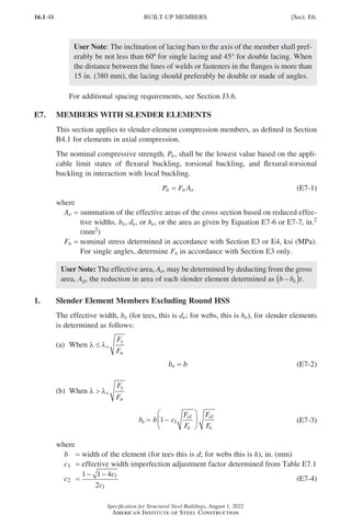
TABLE E7.1
Effective Width Imperfection Adjustment Factors,
c1 and c2
Case Slender Element c1 c2
(a) Stiffened elements except walls of square and rectangular HSS 0.18 1.31
(b) Walls of square and rectangular HSS 0.20 1.38
(c) All other elements 0.22 1.49
λ = width-to-thickness ratio for the element as defined in Section B4.1
λr = limiting width-to-thickness ratio as defined in Table B4.1a
Fel = c F
r
y
2
2
λ
λ
(E7-5)
=
elastic local buckling stress determined according to Equation E7-5 or an
elastic local buckling analysis, ksi (MPa)
2. Round HSS
The effective area, Ae, is determined as follows:
(a) When
D
t
E
Fy
≤ 0 11
.
Ae = Ag (E7-6)
(b) When 0 11 0 45
. .
E
F
D
t
E
F
y y
A
E
F D t
A
e
y
g
= +
0 038 2
3
.
( / )
(E7-7)
where
D = outside diameter of round HSS, in. (mm)
t = thickness of wall, in. (mm)
Sect. E7.] MEMBERS WITH SLENDER ELEMENTS
Part 16.1 A-F (001-074).indd 49
Part 16.1 A-F (001-074).indd 49 2023-01-10 7:31 PM
2023-01-10 7:31 PM](https://image.slidesharecdn.com/aisc360-22specificationforstructuralsteelbuildings-231108145904-1b416cfe/85/AISC-360-22-Specification-for-Structural-Steel-Buildings-pdf-117-320.jpg)
![16.1-51
Specification for Structural Steel Buildings, August 1, 2022
American Institute of Steel Construction
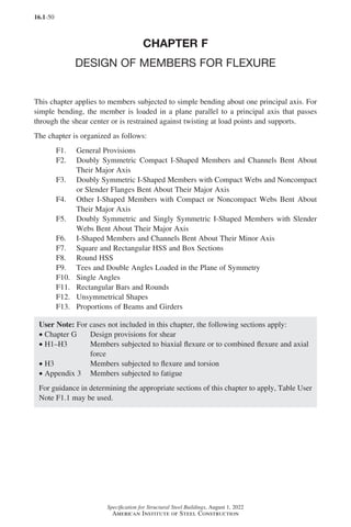
TABLE USER NOTE F1.1
Selection Table for the Application
of Chapter F Sections
Section in
Chapter F
Cross
Section
Flange
Slenderness
Web
Slenderness
Limit
States
F2 C C Y, LTB
F3 NC, S C LTB, FLB
F4 C, NC, S C, NC
CFY, LTB,
FLB, TFY
F5 C, NC, S S
CFY, LTB,
FLB, TFY
F6 C, NC, S NA Y, FLB
F7 C, NC, S C, NC, S
Y, FLB, WLB,
LTB
F8 NA NA Y, LB
F9 C, NC, S NA
Y, LTB, FLB,
WLB
F10 NA NA Y, LTB, LLB
F11 NA NA Y, LTB
F12
Unsymmetrical shapes,
other than single angles
NA NA
All limit
states
C = compact; CFY = compression flange yielding; FLB = flange local buckling; LB = local buckling; LLB = leg
local buckling; LTB = lateral-torsional buckling; NC = noncompact; S = slender; TFY = tension flange yielding;
WLB = web local buckling; Y = yielding; NA = not applicable
Chap. F.] DESIGN OF MEMBERS FOR FLEXURE
Part 16.1 A-F (001-074).indd 51
Part 16.1 A-F (001-074).indd 51 2023-01-10 7:31 PM
2023-01-10 7:31 PM](https://image.slidesharecdn.com/aisc360-22specificationforstructuralsteelbuildings-231108145904-1b416cfe/85/AISC-360-22-Specification-for-Structural-Steel-Buildings-pdf-119-320.jpg)
![16.1-53
Specification for Structural Steel Buildings, August 1, 2022
American Institute of Steel Construction
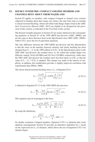
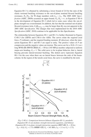
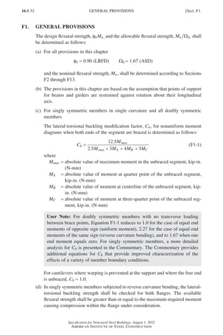
F2.
DOUBLY SYMMETRIC COMPACT I-SHAPED MEMBERS AND
CHANNELS BENT ABOUT THEIR MAJOR AXIS
This section applies to doubly symmetric I-shaped members and channels bent about
their major axis, having compact webs and compact flanges as defined in Section
B4.1 for flexure.
User Note: For Fy = 50 ksi (345 MPa), all current ASTM A6/A6M W, S, M,
C, and MC shapes except W21×48, W14×99, W14×90, W12×65, W10×12,
W8×31, W8×10, W6×15, W6×9, W6×8.5, and M4×6 have compact flanges.
For Fy ≤ 70 ksi (485 MPa), all current ASTM A6/A6M W, S, M, HP, C, and MC
shapes have compact webs.
The nominal flexural strength, Mn, shall be the lower value obtained according to the
limit states of yielding (plastic moment) and lateral-torsional buckling.
1. Yielding
Mn = Mp = Fy Zx (F2-1)
where
Fy = specified minimum yield stress of the type of steel being used, ksi (MPa)
Zx = plastic section modulus about the x-axis, in.3 (mm3)
2. Lateral-Torsional Buckling
(a) When Lb ≤ Lp, the limit state of lateral-torsional buckling does not apply.
(b) When Lp Lb ≤ Lr
M C M M F S
L L
L L
M
n b p p y x
b p
r p
p
= − −
( )
−
−
≤
0 7
. (F2-2)
(c) When Lb Lr
Mn = Fcr Sx ≤ Mp (F2-3)
where
Lb =
length between points that are either braced against lateral displacement of
the compression flange or braced against twist of the cross section, in. (mm)
Fcr = critical stress, ksi (MPa)
=
C E
L
r
Jc
S h
L
r
b
b
ts
x o
b
ts
π2
2
2
1 0 078
+
. (F2-4)
E = modulus of elasticity of steel
=
29,000 ksi (200 000 MPa)
J = torsional constant, in.4 (mm4)
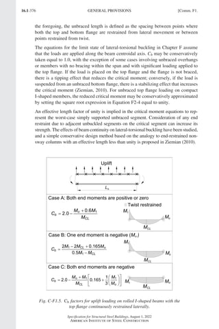
Sx = elastic section modulus taken about the x-axis, in.3 (mm3)
ho = distance between the flange centroids, in. (mm)
Sect. F2.] DOUBLY SYMMETRIC COMPACT I-SHAPED MEMBERS AND CHANNELS
Part 16.1 A-F (001-074).indd 53
Part 16.1 A-F (001-074).indd 53 2023-01-10 7:31 PM
2023-01-10 7:31 PM](https://image.slidesharecdn.com/aisc360-22specificationforstructuralsteelbuildings-231108145904-1b416cfe/85/AISC-360-22-Specification-for-Structural-Steel-Buildings-pdf-121-320.jpg)

![16.1-55
Specification for Structural Steel Buildings, August 1, 2022
American Institute of Steel Construction
r
I h
S
ts
y o
x
2
2
=
rts may be approximated accurately to conservatively as the radius of gyration
of the compression flange plus one-sixth of the web:
r
b
ht
b t
ts
f
w
f f
=
+
12 1
1
6
F3.
DOUBLY SYMMETRIC I-SHAPED MEMBERS WITH COMPACT
WEBS AND NONCOMPACT OR SLENDER FLANGES BENT
ABOUT THEIR MAJOR AXIS
This section applies to doubly symmetric I-shaped members bent about their major
axis having compact webs and noncompact or slender flanges as defined in Section
B4.1 for flexure.
User Note: The following shapes have noncompact flanges for Fy = 50 ksi (345
MPa): W21×48, W14×99, W14×90, W12×65, W10×12, W8×31, W8×10,
W6×15, W6×9, W6×8.5, and M4×6. All other ASTM A6/A6M W, S, and M
shapes have compact flanges for Fy ≤ 50 ksi (345 MPa).
The nominal flexural strength, Mn, shall be the lower value obtained according to
the limit states of lateral-torsional buckling and compression flange local buckling.
1. Lateral-Torsional Buckling
For lateral-torsional buckling, the provisions of Section F2.2 shall apply.
2. Compression Flange Local Buckling
(a) For sections with noncompact flanges
M M M F S
n p p y x
pf
rf pf
= − −
( )
−
−
0 7
.
λ λ
λ λ
(F3-1)
(b) For sections with slender flanges
M
Ek S
n
c x
=
0 9
2
.
λ
(F3-2)
where
kc =
4
h tw
and shall not be taken as less than 0.35 nor greater than 0.76 for
calculation purposes
h = distance as defined in Section B4.1b, in. (mm)
tw = thickness of the web, in. (mm)
Sect. F3.] DOUBLY SYMMETRIC I-SHAPED MEMBERS WITH COMPACT WEBS
Part 16.1 A-F (001-074).indd 55
Part 16.1 A-F (001-074).indd 55 2023-01-29 11:51 AM
2023-01-29 11:51 AM](https://image.slidesharecdn.com/aisc360-22specificationforstructuralsteelbuildings-231108145904-1b416cfe/85/AISC-360-22-Specification-for-Structural-Steel-Buildings-pdf-123-320.jpg)
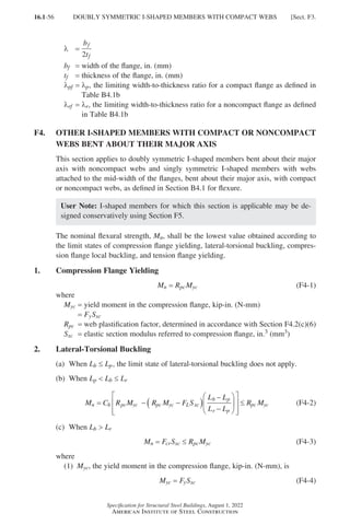
![16.1-57
Specification for Structural Steel Buildings, August 1, 2022
American Institute of Steel Construction
(2) Fcr, the critical stress, ksi (MPa), is
F
C E
L
r
J
S h
L
r
cr
b
b
t
xc o
b
t
=
+
π2
2
2
1 0 078
. (F4-5)
For
I
I
yc
y
≤ 0.23, J shall be taken as zero,
where
Iyc =
moment of inertia of the compression flange about the y-axis, in.4
(mm4)
(3)
FL, nominal compression flange stress above which the inelastic buckling
limit states apply, ksi (MPa), is determined as follows:
(i) When
S
S
xt
xc
≥ 0 7
.
FL = 0.7Fy (F4-6a)
(ii) When
S
S
xt
xc
0 7
.
F F
S
S
F
L y
xt
xc
y
= ≥ 0 5
. (F4-6b)
where
Sxt = elastic section modulus referred to tension flange, in.3 (mm3)
(4)
Lp, the limiting laterally unbraced length for the limit state of yielding, in.
(mm), is
Lp = 1.1rt
F
E
y
(F4-7)
(5)
Lr, the limiting unbraced length for the limit state of inelastic lateral-
torsional buckling, in. (mm), is
L r
E
F
J
S h
J
S h
F
E
r t
L xc o xc o
L
= +
+
1 95 6 76
2 2
. . (F4-8)
(6) Rpc, the web plastification factor, is determined as follows:
(i) When I I
yc y 0 23
.
(a) When
h
t
c
w
pw
≤ λ
R
M
M
pc
p
yc
= (F4-9a)
Sect. F4.] OTHER I-SHAPED MEMBERS WITH COMPACT OR NONCOMPACT WEBS
Part 16.1 A-F (001-074).indd 57
Part 16.1 A-F (001-074).indd 57 2023-01-10 7:31 PM
2023-01-10 7:31 PM](https://image.slidesharecdn.com/aisc360-22specificationforstructuralsteelbuildings-231108145904-1b416cfe/85/AISC-360-22-Specification-for-Structural-Steel-Buildings-pdf-125-320.jpg)
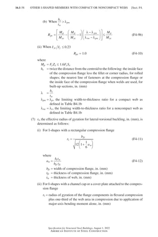
![16.1-59
Specification for Structural Steel Buildings, August 1, 2022
American Institute of Steel Construction
3. Compression Flange Local Buckling
(a)
For sections with compact flanges, the limit state of local buckling does not apply.
(b) For sections with noncompact flanges
M R M R M F S
n pc yc pc yc L xc
pf
rf pf
= − −
( )
−
−
λ λ
λ λ
(F4-13)
(c) For sections with slender flanges
M
Ek S
n
c xc
=
0 9
2
.
λ
(F4-14)
where
FL is defined in Equations F4-6a and F4-6b
Rpc is the web plastification factor, determined by Equation F4-9a, F4-9b, or F4-10
k
h t
c
w
=
4
and shall not be taken as less than 0.35 nor greater than 0.76 for cal-
culation purposes
λ =
b
t
fc
fc
2
λpf =
λp, the limiting width-to-thickness ratio for a compact flange as defined in
Table B4.1b
λrf =
λr, the limiting width-to-thickness ratio for a noncompact flange as defined
in Table B4.1b
4. Tension Flange Yielding
(a) When Sxt ≥ Sxc, the limit state of tension flange yielding does not apply.
(b) When Sxt Sxc
Mn = RptMyt (F4-15)
where
Myt = yield moment in the tension flange, kip-in. (N-mm)
=
FySxt
Rpt, the web plastification factor corresponding to the tension flange yielding
limit state, is determined as follows:
(1) When Iyc Iy 0.23
(i) When
h
t
c
w
pw
≤ λ
R
M
M
pt
p
yt
= (F4-16a)
(ii) When
h
t
c
w
pw
λ
R
M
M
M
M
M
M
pt
p
yt
p
yt
pw
rw pw
p
yt
= − −
−
−
≤
1
λ λ
λ λ
(F4-16b)
Sect. F4.] OTHER I-SHAPED MEMBERS WITH COMPACT OR NONCOMPACT WEBS
Part 16.1 A-F (001-074).indd 59
Part 16.1 A-F (001-074).indd 59 2023-01-10 7:31 PM
2023-01-10 7:31 PM](https://image.slidesharecdn.com/aisc360-22specificationforstructuralsteelbuildings-231108145904-1b416cfe/85/AISC-360-22-Specification-for-Structural-Steel-Buildings-pdf-127-320.jpg)
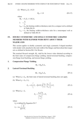
![16.1-61
Specification for Structural Steel Buildings, August 1, 2022
American Institute of Steel Construction
rt =
effective radius of gyration for lateral-torsional buckling as defined in Section
F4, in. (mm)
Rpg, the bending strength reduction factor, is
R
a
a
h
t
E
F
pg
w
w
c
w y
= −
+
−
≤
1
1 200 300
5 7 1 0
,
. . (F5-6)
aw is defined by Equation F4-12, but shall not exceed 10
3. Compression Flange Local Buckling
Mn =
RpgFcrSxc (F5-7)
(a)
For sections with compact flanges, the limit state of compression flange local
buckling does not apply.
(b) For sections with noncompact flanges
F F F
cr y y
pf
rf pf
= − ( )
−
−
0 3
.
λ λ
λ λ
(F5-8)
(c) For sections with slender flanges
F
Ek
b
t
cr
c
f
f
=
0 9
2
2
.
(F5-9)
where
kc =
4
h tw
and shall not be taken as less than 0.35 nor greater than 0.76 for cal-
culation purposes
λ =
b
t
fc
fc
2
λpf =
λp, the limiting width-to-thickness ratio for a compact flange as defined in
Table B4.1b
λrf =
λr, the limiting width-to-thickness ratio for a noncompact flange as defined
in Table B4.1b
4. Tension Flange Yielding
(a) When Sxt ≥ Sxc, the limit state of tension flange yielding does not apply.
(b) When Sxt Sxc
Mn = FySxt (F5-10)
F6.
I-SHAPED MEMBERS AND CHANNELS BENT ABOUT THEIR
MINOR AXIS
This section applies to I-shaped members and channels bent about their minor axis.
The nominal flexural strength, Mn, shall be the lower value obtained according to the
limit states of yielding (plastic moment) and flange local buckling.
Sect. F6.] I-SHAPED MEMBERS AND CHANNELS BENT ABOUT THEIR MINOR AXIS
Part 16.1 A-F (001-074).indd 61
Part 16.1 A-F (001-074).indd 61 2023-01-10 7:31 PM
2023-01-10 7:31 PM](https://image.slidesharecdn.com/aisc360-22specificationforstructuralsteelbuildings-231108145904-1b416cfe/85/AISC-360-22-Specification-for-Structural-Steel-Buildings-pdf-129-320.jpg)
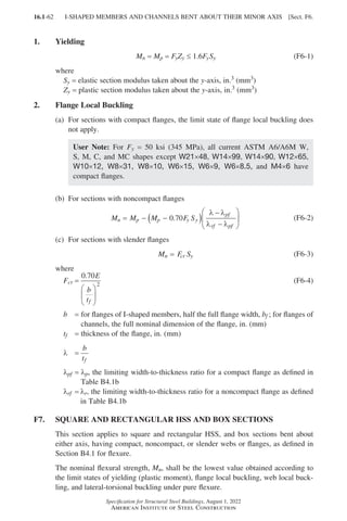
![16.1-63
Specification for Structural Steel Buildings, August 1, 2022
American Institute of Steel Construction
1. Yielding
Mn =
Mp = FyZ (F7-1)
where
Z = plastic section modulus about the axis of bending, in.3 (mm3)
2. Flange Local Buckling
(a) For compact sections, the limit state of flange local buckling does not apply.
(b) For sections with noncompact flanges
M M M F S M
n p p y
pf
rf pf
p
= − −
( )
−
−
≤
λ λ
λ λ
(F7-2)
where
S = elastic section modulus about the axis of bending, in.3 (mm3)
λ =
b
tf
b = width of compression flange as defined in Section B4.1b, in. (mm)
tf = thickness of the flange, in. (mm)
λpf =
λp, the limiting width-to-thickness ratio for a compact flange as defined
in Table B4.1b
λrf =
λr, the limiting width-to-thickness ratio for a noncompact flange as
defined in Table B4.1b
(c) For sections with slender flanges
Mn =
FySe (F7-3)
where
Se =
effective section modulus determined with the effective width, be, of the
compression flange taken as follows:
(1) For HSS
b t
E
F b t
E
F
b
e f
y f y
= −
≤
1 92 1
0 38
.
.
(F7-4)
(2) For box sections
b t
E
F b t
E
F
b
e f
y f y
= −
≤
1 92 1
0 34
.
.
(F7-5)
3. Web Local Buckling
(a) For compact sections, the limit state of web local buckling does not apply.
(b) For sections with noncompact webs
M M M F S M
n p p y
pw
rw pw
p
= − −
( )
−
−
≤
λ λ
λ λ
(F7-6)
Sect. F7.] SQUARE AND RECTANGULAR HSS AND BOX SECTIONS
Part 16.1 A-F (001-074).indd 63
Part 16.1 A-F (001-074).indd 63 2023-01-10 7:31 PM
2023-01-10 7:31 PM](https://image.slidesharecdn.com/aisc360-22specificationforstructuralsteelbuildings-231108145904-1b416cfe/85/AISC-360-22-Specification-for-Structural-Steel-Buildings-pdf-131-320.jpg)
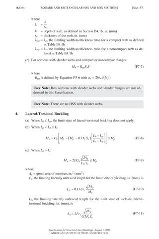
![16.1-65
Specification for Structural Steel Buildings, August 1, 2022
American Institute of Steel Construction
User Note: Lateral-torsional buckling will not occur in square sections or sec-
tions bending about their minor axis. In HSS sizes, deflection will usually control
before there is a significant reduction in flexural strength due to lateral-torsional
buckling. The same is true for box sections, and lateral-torsional buckling will
usually only be a consideration for sections with high depth-to-width ratios.
F8. ROUND HSS
This section applies to round HSS having D t ratios of less than
0 45
. E
Fy
.
The nominal flexural strength, Mn, shall be the lower value obtained according to the
limit states of yielding (plastic moment) and local buckling.
1. Yielding
Mn =
Mp = FyZ (F8-1)
2. Local Buckling
(a) For compact sections, the limit state of flange local buckling does not apply.
(b) For noncompact sections
M
E
D
t
F S
n y
=
+
0 021
.
(F8-2)
(c) For sections with slender walls
Mn =
FcrS (F8-3)
where
D = outside diameter of round HSS, in. (mm)
Fcr =
0 33
. E
D
t
(F8-4)
t = design wall thickness of HSS member, in. (mm)
F9.
TEES AND DOUBLE ANGLES LOADED IN THE PLANE OF
SYMMETRY
This section applies to tees and double angles loaded in the plane of symmetry.
The nominal flexural strength, Mn, shall be the lowest value obtained according to
the limit states of yielding (plastic moment), lateral-torsional buckling, flange local
buckling, and local buckling of tee stems and double angle web legs.
1. Yielding
Mn = Mp (F9-1)
Sect. F9.] TEES AND DOUBLE ANGLES LOADED IN THE PLANE OF SYMMETRY
Part 16.1 A-F (001-074).indd 65
Part 16.1 A-F (001-074).indd 65 2023-01-10 7:31 PM
2023-01-10 7:31 PM](https://image.slidesharecdn.com/aisc360-22specificationforstructuralsteelbuildings-231108145904-1b416cfe/85/AISC-360-22-Specification-for-Structural-Steel-Buildings-pdf-133-320.jpg)
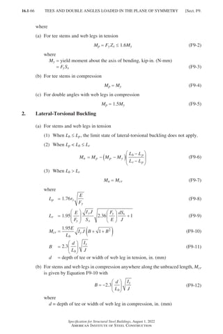
![16.1-67
Specification for Structural Steel Buildings, August 1, 2022
American Institute of Steel Construction
(1) For tee stems
Mn =
Mcr ≤ My (F9-13)
(2)
For double-angle web legs, Mn shall be determined using Equations F10-2
and F10-3 with Mcr determined using Equation F9-10 and My determined
using Equation F9-3.
3. Flange Local Buckling of Tees and Double-Angle Legs
(a) For tee flanges
(1)
For sections with a compact flange in flexural compression, the limit state
of flange local buckling does not apply.
(2) For sections with a noncompact flange in flexural compression
M M M F S M
n p p y xc
pf
rf pf
y
= − −
( )
−
−
≤
0 7 1 6
. .
λ λ
λ λ
(F9-14)
(3) For sections with a slender flange in flexural compression
M
ES
b
t
n
xc
f
f
=
0 7
2
2
.
(F9-15)
where
Sxc = elastic section modulus referred to the compression flange, in.3 (mm3)
l =
b
t
f
f
2
lpf =
lp, the limiting width-to-thickness ratio for a compact flange as defined
in Table B4.1b
lrf =
lr, the limiting width-to-thickness ratio for a noncompact flange as
defined in Table B4.1b
(b) For double-angle flange legs
The nominal flexural strength, Mn, for double angles with the flange legs in com-
pression shall be determined in accordance with Section F10.3, with Sc referred
to the compression flange.
4.
Local Buckling of Tee Stems and Double-Angle Web Legs in
Flexural Compression
(a) For tee stems
Mn =
FcrSx (F9-16)
where
Sx = elastic section modulus taken about the x-axis, in.3 (mm3)
Fcr, the critical stress, is determined as follows:
(1) When
d
t
E
F
w y
≤ 0 84
.
Sect. F9.] TEES AND DOUBLE ANGLES LOADED IN THE PLANE OF SYMMETRY
Part 16.1 A-F (001-074).indd 67
Part 16.1 A-F (001-074).indd 67 2023-01-10 7:31 PM
2023-01-10 7:31 PM](https://image.slidesharecdn.com/aisc360-22specificationforstructuralsteelbuildings-231108145904-1b416cfe/85/AISC-360-22-Specification-for-Structural-Steel-Buildings-pdf-135-320.jpg)
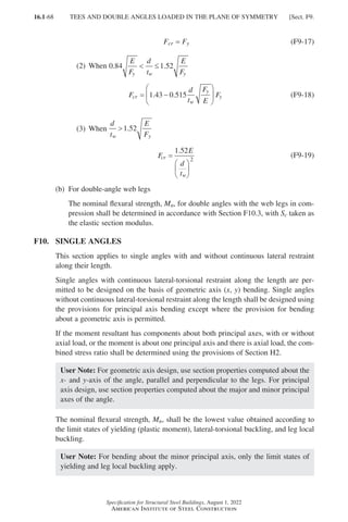
![16.1-69
Specification for Structural Steel Buildings, August 1, 2022
American Institute of Steel Construction
1. Yielding
Mn = 1.5My (F10-1)
2. Lateral-Torsional Buckling
For single angles without continuous lateral-torsional restraint along the length
(a) When
M
M
y
cr
≤1 0
.
M
M
M
M M
n
y
cr
y y
= −
≤
1 92 1 17 1 5
. . . (F10-2)
(b) When
M
M
y
cr
1 0
.
M
M
M
M
n
cr
y
cr
= −
0 92
0 17
.
.
(F10-3)
where
Mcr, the elastic lateral-torsional buckling moment, is determined as follows:
(1) For bending about the major principal axis of single angles
M
EA r tC
L
r
L t
r
L t
cr
g z b
b
w z
b
w z
b
= +
+
9
8
1 4 4 4 4
2
. .
β β
(F10-4)
where
Cb is computed using Equation F1-1 with a maximum value of 1.5
Ag = gross area of angle, in.2 (mm2)
Lb = laterally unbraced length of member, in. (mm)
rz = radius of gyration about the minor principal axis, in. (mm)
t = thickness of angle leg, in. (mm)
βw =
section property for single angles about major principal axis, in. (mm).
βw ispositivewithshortlegsincompressionandnegativewithlonglegs
in compression for unequal-leg angles, and zero for equal-leg angles.
If the long leg is in compression anywhere along the unbraced length
of the member, the negative value of βw shall be used.
User Note: The equation for βw and values for common angle sizes are
listed in the Commentary.
(2)
For bending about one of the geometric axes of an equal-leg angle with no
axial compression
(i) With no lateral-torsional restraint
(a) With maximum compression at the toe
M
Eb tC
L
L t
b
cr
b
b
b
= +
−
0 58
1 0 88 1
4
2 2
2
.
. (F10-5a)
Sect. F10.] SINGLE ANGLES
Part 16.1 A-F (001-074).indd 69
Part 16.1 A-F (001-074).indd 69 2023-01-10 7:31 PM
2023-01-10 7:31 PM](https://image.slidesharecdn.com/aisc360-22specificationforstructuralsteelbuildings-231108145904-1b416cfe/85/AISC-360-22-Specification-for-Structural-Steel-Buildings-pdf-137-320.jpg)
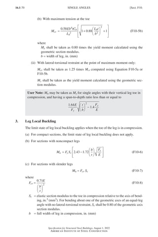
![16.1-71
Specification for Structural Steel Buildings, August 1, 2022
American Institute of Steel Construction
F11. RECTANGULAR BARS AND ROUNDS
This section applies to rectangular bars bent about either geometric axis, and rounds.
The nominal flexural strength, Mn, shall be the lower value obtained according to the
limit states of yielding (plastic moment) and lateral-torsional buckling.
1. Yielding
For rectangular bars
Mn =
Mp =
FyZ ≤ 1.5FySx (F11-1)
For rounds
Mn =
Mp =
FyZ ≤ 1.6FySx (F11-2)
2. Lateral-Torsional Buckling
(a)
For rectangular bars with
L d
t
E
F
b
y
2
0 08
≤
.
bent about their major axis, rectangular
bars bent about their minor axis, and rounds, the limit state of lateral-torsional
buckling does not apply.
(b) For rectangular bars with
0 08 1 9
2
. .
E
F
L d
t
E
F
y
b
y
≤ bent about their major axis
M C
L d
t
F
E
M M
n b
b y
y p
= −
≤
1 52 0 274 2
. . (F11-3)
where
Lb =
length between points that are either braced against lateral displacement
of the compression region, or between points braced to prevent twist of
the cross section, in. (mm)
(c) For rectangular bars with
L d
t
E
F
b
y
2
1 9
.
bent about their major axis
Mn = FcrSx ≤ Mp (F11-4)
where
F
EC
L d
t
cr
b
b
=
1 9
2
.
(F11-5)
F12. UNSYMMETRICAL SHAPES
This section applies to all unsymmetrical shapes except single angles.
The nominal flexural strength, Mn, shall be the lowest value obtained according
to the limit states of yielding (yield moment), lateral-torsional buckling, and local
buckling where
Mn = FnSmin (F12-1)
Sect. F12.] UNSYMMETRICAL SHAPES
Part 16.1 A-F (001-074).indd 71
Part 16.1 A-F (001-074).indd 71 2023-01-10 7:31 PM
2023-01-10 7:31 PM](https://image.slidesharecdn.com/aisc360-22specificationforstructuralsteelbuildings-231108145904-1b416cfe/85/AISC-360-22-Specification-for-Structural-Steel-Buildings-pdf-139-320.jpg)
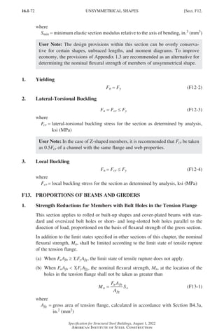
![16.1-73
Specification for Structural Steel Buildings, August 1, 2022
American Institute of Steel Construction
Afn =
net area of tension flange, calculated in accordance with Section B4.3b, in.2
(mm2)
Fu = specified minimum tensile strength, ksi (MPa)
Sx = minimum elastic section modulus taken about the x-axis, in.3 (mm3)
Yt = 1.0 for Fy Fu ≤ 0.8
= 1.1 otherwise
2. Proportioning Limits for I-Shaped Members
Singly symmetric I-shaped members shall satisfy the following limit:
0 1 0 9
. .
≤ ≤
I
I
yc
y
(F13-2)
Singly and doubly symmetric I-shaped members with slender webs shall satisfy the
following limits:
(a) When
(a) When
a
h
≤1 5
.
h
t
E
F
w max y
=12 0
. (F13-3)
(b) When
(b) When
a
h
1 5
.
h
t
E
F
w max y
=
0 40
.
(F13-4)
where
a = clear distance between transverse stiffeners, in. (mm)
In unstiffened girders, h tw shall not exceed 260. The ratio of 2 times the web area
in compression to the compression flange area, aw, as defined by Equation F4-12,
shall not exceed 10.
3. Cover Plates
(a)
For members with cover plates, the following provisions apply: Flanges of
welded beams or girders are permitted to be varied in thickness or width by
splicing a series of plates or by the use of cover plates.
(b)
High-strength bolts or welds connecting flange to web, or cover plate to flange,
shall be proportioned to resist the total horizontal shear resulting from the
bending forces on the girder. The longitudinal distribution of these bolts or
intermittent welds shall be in proportion to the intensity of the shear.
(c)
However, the longitudinal spacing shall not exceed the maximum specified for
compression or tension members in Section E6 or D4, respectively. Bolts or
welds connecting flange to web shall also be proportioned to transmit to the web
any loads applied directly to the flange, unless provision is made to transmit such
loads by direct bearing.
(d)
Partial-length cover plates shall be extended beyond the theoretical cutoff point
and the extended portion shall be attached to the beam or girder by high-strength
Sect. F13.] PROPORTIONS OF BEAMS AND GIRDERS
Part 16.1 A-F (001-074).indd 73
Part 16.1 A-F (001-074).indd 73 2023-01-10 7:31 PM
2023-01-10 7:31 PM](https://image.slidesharecdn.com/aisc360-22specificationforstructuralsteelbuildings-231108145904-1b416cfe/85/AISC-360-22-Specification-for-Structural-Steel-Buildings-pdf-141-320.jpg)
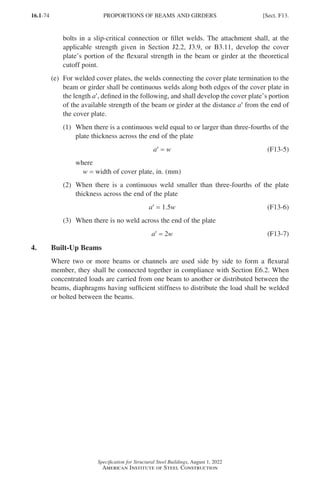
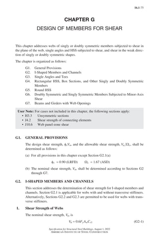
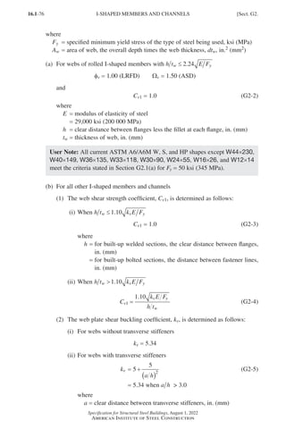
![16.1-77
Specification for Structural Steel Buildings, August 1, 2022
American Institute of Steel Construction
User Note: Cv1 = 1.0 for all ASTM A6/A6M W, S, M, and HP shapes except
M12.5×12.4, M12.5×11.6, M12×11.8, M12×10.8, M12×10, M10×8, and
M10×7.5, when Fy = 50 ksi (345 MPa).
2.
Shear Strength of Interior Web Panels with a h ≤
≤ 3 Considering
Tension Field Action
The nominal shear strength, Vn, is determined as follows:
(a) When h t k E F
w v y
≤1 10
.
Vn = 0.6FyAw (G2-6)
(b) When h t k E F
w v y
1 10
.
(1) When 2 2 5
A A A
w fc ft
+
( )≤ . , h bfc ≤ 6 0
. , and h bft ≤ 6 0
.
V F A C
C
a h
n y w v
v
= +
−
+ ( )
0 6
1
1 15 1
2
2
2
.
.
(G2-7)
(2) Otherwise
V F A C
C
a h a h
n y w v
v
= +
−
+ + ( )
0 6
1
1 15 1
2
2
2
.
.
(G2-8)
where
the web shear buckling coefficient, Cv2, is determined as follows:
(i) When h t k E F
w v y
≤1 10
.
Cv2 = 1.0 (G2-9)
(ii) When 1 10 1 37
. .
k E F h t k E F
v y w v y
≤
C
k E F
h t
v
v y
w
2
1 10
=
.
(G2-10)
(iii) When h t k E F
w v y
1 37
.
C
k E
h t F
v
v
w y
2 2
1 51
=
( )
.
(G2-11)
Afc = area of compression flange, in.2 (mm2)
Aft = area of tension flange, in.2 (mm2)
bfc = width of compression flange, in. (mm)
bft = width of tension flange, in. (mm)
kv is as defined in Section G2.1(b)(2)
Sect. G2.] I-SHAPED MEMBERS AND CHANNELS
Part 16.1 G-I (075-120).indd 77
Part 16.1 G-I (075-120).indd 77 2023-01-10 7:41 PM
2023-01-10 7:41 PM](https://image.slidesharecdn.com/aisc360-22specificationforstructuralsteelbuildings-231108145904-1b416cfe/85/AISC-360-22-Specification-for-Structural-Steel-Buildings-pdf-145-320.jpg)
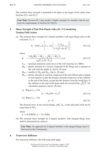
![16.1-79
Specification for Structural Steel Buildings, August 1, 2022
American Institute of Steel Construction
(a)
Transverse stiffeners are not required where h t E F
w y
≤ 2 54
. , or where the
available shear strength provided in accordance with Section G2.1 for kv = 5.34
is greater than the required shear strength.
(b)
Transverse stiffeners are permitted to be stopped short of the tension flange,
provided bearing is not needed to transmit a concentrated load or reaction. The
weld by which transverse stiffeners are attached to the web shall be terminated
not less than four times nor more than six times the web thickness from the near
toe of the web-to-flange weld or web-to-flange fillet. When stiffeners are used,
they shall be detailed to resist twist of the compression flange.
(c)
Bolts connecting stiffeners to the girder web shall be spaced not more than
12 in. (300 mm) on center. If intermittent fillet welds are used, the clear distance
between welds shall not be more than 16 times the web thickness nor more than
10 in. (250 mm).
(d) b t
E
F
st
yst
( ) ≤ 0 56
. (G2-16)
(e) I I I I
st st st st w
≥ + −
( )
2 1 2 ρ (G2-17)
where
Fyst = specified minimum yield stress of the stiffener material, ksi (MPa)
Ist =
moment of inertia of the transverse stiffeners about an axis in the web
center for stiffener pairs, or about the face in contact with the web plate
for single stiffeners, in.4 (mm4)
Ist1 =
minimum moment of inertia of the transverse stiffeners required for
development of the full shear post-buckling resistance of the stiffened
web panels, Vr = Vc1, in.4 (mm4)
=
h F
E
st yw
4 1 3 1 5
40
ρ . .
(G2-18)
Ist2 =
minimum moment of inertia of the transverse stiffeners required for
development of the web shear buckling resistance, Vr = Vc2, in.4 (mm4)
=
2 5
2 0 5
2
3 3
.
.
a h
b t b t
p w p w
( )
−
≥ (G2-19)
Vc1 =
available shear strength calculated with Vn as defined in Section G2.1 or
G2.2, as applicable, kips (N)
Vc2 = available shear strength, kips (N), calculated with Vn = 0.6FyAwCv2
Vr = required shear strength in the panel being considered, kips (N)
bp = smaller of the dimensions a and h, in. (mm)
b t st
( ) = width-to-thickness ratio of the stiffener
rst = larger of F F
yw yst and 1.0
rw =
maximum shear ratio,
V V
V V
r c
c c
−
−
≥
2
1 2
0 within the web panels on each side
of the transverse stiffener
Sect. G2.] I-SHAPED MEMBERS AND CHANNELS
Part 16.1 G-I (075-120).indd 79
Part 16.1 G-I (075-120).indd 79 2023-01-10 7:41 PM
2023-01-10 7:41 PM](https://image.slidesharecdn.com/aisc360-22specificationforstructuralsteelbuildings-231108145904-1b416cfe/85/AISC-360-22-Specification-for-Structural-Steel-Buildings-pdf-147-320.jpg)
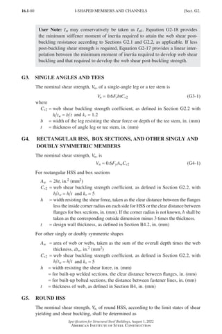
![16.1-81
Specification for Structural Steel Buildings, August 1, 2022
American Institute of Steel Construction
V F A
n cr g
= 2 (G5-1)
where
Fcr shall be the larger of
F
E
L
D
D
t
cr
v
=
1 60
5
4
.
(G5-2a)
and
F
E
D
t
cr =
0 78
3
2
.
(G5-2b)
but shall not exceed 0.6Fy
Ag = gross area of member, in.2 (mm2)
D = outside diameter, in. (mm)
Lv = distance from maximum to zero shear force, in. (mm)
t = design wall thickness, in. (mm)
User Note: The shear buckling equations, Equations G5-2a and G5-2b, will con-
trol for D t over 100, high-strength steels, and long lengths. For standard sections,
shear yielding will usually control and Fcr = 0.6Fy.
G6.
DOUBLY SYMMETRIC AND SINGLY SYMMETRIC MEMBERS
SUBJECTED TO MINOR-AXIS SHEAR
For doubly and singly symmetric members loaded in the minor axis without torsion,
the nominal shear strength, Vn, for each shear resisting element is
Vn = 0.6FybftfCv2 (G6-1)
where
Cv2 =
web shear buckling strength coefficient, as defined in Section G2.2 with
h t b t
w f f
= 2 for I-shaped members and tees, or h t b t
w f f
= for channels,
and kv = 1.2
bf = width of flange, in. (mm)
tf = thickness of flange, in. (mm)
User Note: Cv2 = 1.0 for all ASTM A6/A6M W, S, M, and HP shapes, when
Fy ≤ 70 ksi (485 MPa).
G7. BEAMS AND GIRDERS WITH WEB OPENINGS
The effect of all web openings on the shear strength of steel and composite beams
shall be determined. Reinforcement shall be provided when the required strength
exceeds the available strength of the member at the opening.
Sect. G7.] BEAMS AND GIRDERS WITH WEB OPENINGS
Part 16.1 G-I (075-120).indd 81
Part 16.1 G-I (075-120).indd 81 2023-01-10 7:41 PM
2023-01-10 7:41 PM](https://image.slidesharecdn.com/aisc360-22specificationforstructuralsteelbuildings-231108145904-1b416cfe/85/AISC-360-22-Specification-for-Structural-Steel-Buildings-pdf-149-320.jpg)
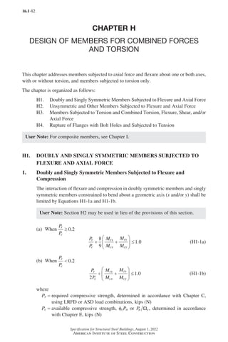
![16.1-83
Specification for Structural Steel Buildings, August 1, 2022
American Institute of Steel Construction
Mr = required flexural strength, determined in accordance with Chapter C, using
LRFD or ASD load combinations, kip-in. (N-mm)
Mc =
available flexural strength, fbMn or Mn b
Ω , determined in accordance with
Chapter F, kip-in. (N-mm)
x = subscript relating symbol to major-axis bending
y = subscript relating symbol to minor-axis bending
User Note: All terms in Equations H1-1a and H1-1b are to be taken as positive.
2. Doubly and Singly Symmetric Members Subjected to Flexure and Tension
The interaction of flexure and tension in doubly symmetric members and singly
symmetric members constrained to bend about a geometric axis (x and/or y) shall be
limited by Equations H1-1a and H1-1b,
where
Pr =
required tensile strength, determined in accordance with Chapter C, using
LRFD or ASD load combinations, kips (N)
Pc =
available tensile strength, ftPn or Pn t
Ω , determined in accordance with
Chapter D, kips (N)
For doubly symmetric members, Cb in Chapter F is permitted to be multiplied by
1+
αP
P
r
ey
when axial tension acts concurrently with flexure,
where
P
EI
L
ey
y
b
=
π2
2
(H1-2)
α =1 0
.
= 1.0 (LRFD); α =1 6
. (ASD)
E = modulus of elasticity of steel
=
29,000 ksi (200 000 MPa)
Iy = moment of inertia about the y-axis, in.4 (mm4)
Lb =
length between points that are either braced against lateral displacement
of the compression flange or braced against twist of the cross section, in.4
(mm4)
3.
Doubly Symmetric Rolled Compact Members Subjected to Single-Axis
Flexure and Compression
For doubly symmetric rolled compact members, with the effective length for tor-
sional buckling less than or equal to the effective length for y-axis flexural buckling,
Lcz ≤ Lcy, subjected to flexure and compression with moments primarily about their
major axis, it is permissible to address the two independent limit states, in-plane
instability and out-of-plane buckling or lateral-torsional buckling, separately in lieu
of the combined approach provided in Section H1.1,
where
Lcy = effective length for buckling about the y-axis, in. (mm)
Lcz = effective length for buckling about the longitudinal axis, in. (mm)
Sect. H1.] DOUBLY AND SINGLY SYMMETRIC MEMBERS
Part 16.1 G-I (075-120).indd 83
Part 16.1 G-I (075-120).indd 83 2023-01-29 11:52 AM
2023-01-29 11:52 AM](https://image.slidesharecdn.com/aisc360-22specificationforstructuralsteelbuildings-231108145904-1b416cfe/85/AISC-360-22-Specification-for-Structural-Steel-Buildings-pdf-151-320.jpg)
![16.1-85
Specification for Structural Steel Buildings, August 1, 2022
American Institute of Steel Construction
User Note: The subscripts w and z refer to the principal axes of the unsym-
metric cross section. For doubly symmetric cross sections, these can be
replaced by the x and y subscripts.
Equation H2-1 shall be evaluated using the principal bending axes by considering the
sense of the flexural stresses at the critical points of the cross section. The flexural
terms are either added to or subtracted from the axial term as applicable. When the
axial force is compression, second-order effects shall be included according to the
provisions of Chapter C.
A more detailed analysis of the interaction of flexure and tension is permitted in lieu
of Equation H2-1.
H3.
MEMBERS SUBJECTED TO TORSION AND COMBINED TORSION,
FLEXURE, SHEAR, AND/OR AXIAL FORCE
1. Round and Rectangular HSS Subjected to Torsion
The design torsional strength, fTTn, and the allowable torsional strength, Tn T
Ω ,
for round and rectangular HSS according to the limit states of torsional yielding and
torsional buckling shall be determined as follows:
Tn = FcrC (H3-1)
fT = 0.90 (LRFD) WT = 1.67 (ASD)
where
C = HSS torsional constant, in.3 (mm3)
The critical stress, Fcr, shall be determined as follows:
(a) For round HSS, Fcr shall be the larger of
(1)
1 23
5 4
. E
L
D
D
t
(H3-2a)
and
(2) F
E
D
t
cr =
0 60
3 2
.
(H3-2b)
but shall not exceed 0.6Fy,
where
D = outside diameter, in. (mm)
L = length of member, in. (mm)
t = design wall thickness defined in Section B4.2, in. (mm)
(b) For rectangular HSS
(1) When h t E Fy
≤ 2 45
.
Sect. H3.] MEMBERS SUBJECTED TO TORSION AND COMBINED TORSION
Part 16.1 G-I (075-120).indd 85
Part 16.1 G-I (075-120).indd 85 2023-01-10 7:41 PM
2023-01-10 7:41 PM](https://image.slidesharecdn.com/aisc360-22specificationforstructuralsteelbuildings-231108145904-1b416cfe/85/AISC-360-22-Specification-for-Structural-Steel-Buildings-pdf-153-320.jpg)
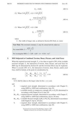
![16.1-87
Specification for Structural Steel Buildings, August 1, 2022
American Institute of Steel Construction
Vc =
available shear strength, fvVn or Vn v
Ω , determined in accordance with
Chapter G, kips (N)
Tr =
required torsional strength, determined in accordance with Chapter C,
using LRFD or ASD load combinations, kip-in. (N-mm)
Tc =
available torsional strength, fTTn or Tn T
Ω , determined in accordance
with Section H3.1, kip-in. (N-mm)
x = subscript relating symbol to major-axis bending
y = subscript relating symbol to minor-axis bending
User Note: All terms in Equations H3-6 are to be taken as positive.
3. Non-HSS Members Subjected to Torsion and Combined Stress
The available torsional strength for non-HSS members shall be the lowest value
obtained according to the limit states of yielding under normal stress, shear yielding
under shear stress, or buckling, determined as follows:
fT = 0.90 (LRFD) WT = 1.67 (ASD)
(a) For the limit state of yielding under normal stress
Fn = Fy (H3-7)
(b) For the limit state of shear yielding under shear stress
Fn = 0.6Fy (H3-8)
(c) For the limit state of buckling
Fn = Fcr (H3-9)
where
Fcr = buckling stress for the section as determined by analysis, ksi (MPa)
H4.
RUPTURE OF FLANGES WITH BOLT HOLES AND SUBJECTED
TO TENSION
At locations of bolt holes in flanges subjected to tension under combined axial force
and major-axis flexure, flange tensile rupture strength shall be limited by Equation
H4-1. Each flange subjected to tension due to axial force and flexure shall be checked
separately.
P
P
M
M
r
c
rx
cx
+ ≤ 1 0
. (H4-1)
where
Pr =
required axial strength of the member at the location of the bolt holes,
determined in accordance with Chapter C, using LRFD or ASD load com-
binations, positive in tension and negative in compression, kips (N)
Pc =
available axial strength for the limit state of tensile rupture of the net sec-
tion at the location of bolt holes, ftPn or Pn t
Ω , determined in accordance
with Section D2(b), kips (N)
Sect. H4.] RUPTURE OF FLANGES WITH BOLT HOLES
Part 16.1 G-I (075-120).indd 87
Part 16.1 G-I (075-120).indd 87 2023-01-29 11:53 AM
2023-01-29 11:53 AM](https://image.slidesharecdn.com/aisc360-22specificationforstructuralsteelbuildings-231108145904-1b416cfe/85/AISC-360-22-Specification-for-Structural-Steel-Buildings-pdf-155-320.jpg)
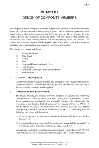
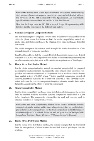
![16.1-91
Specification for Structural Steel Buildings, August 1, 2022
American Institute of Steel Construction
2d. Effective Stress-Strain Method
For the effective stress-strain method, the nominal strength shall be computed
assuming strain compatibility and effective stress-strain relationships for structural
steel, reinforcing steel, and concrete components accounting for the effects of local
buckling, yielding, interaction, and concrete confinement.
3. Material Limitations
For concrete, structural steel, and reinforcing steel in composite systems, the fol-
lowing limitations shall be met unless the design is based on the requirements of
Appendix 2:
(a)
For the determination of the available strength, concrete shall have a specified
compressive strength, ′
fc , of not less than 3 ksi (21 MPa) nor more than 10 ksi
(69 MPa) for normal weight concrete and not less than 3 ksi (21 MPa) nor more
than 6 ksi (41 MPa) for lightweight concrete.
(b)
The specified minimum yield stress of structural steel used in calculating the
strength of composite members shall not exceed 75 ksi (525 MPa).
(c)
The specified minimum yield stress of reinforcing bars used in calculating the
strength of composite members shall not exceed 80 ksi (550 MPa).
The design of filled composite members constructed from materials with strengths
above the limits noted in this section shall be in accordance with Appendix 2.
User Note: Appendix 2 includes equations for determining the available strength
of rectangular filled composite members with either the specified minimum
yield stress of structural steel exceeding 75 ksi (525 MPa) but less than 100 ksi
(690 MPa) or specified compressive strength, ′
fc , exceeding 10 ksi (69 MPa) but
less than 15 ksi (100 MPa).
4. Classification of Filled Composite Sections for Local Buckling
For compression, filled composite sections are classified as compact composite, non-
compact composite, or slender-element composite sections. For a section to qualify
as compact composite, the maximum width-to-thickness ratio, λ, of its compression
steel elements shall not exceed the limiting width-to-thickness ratio, λp, from Table
I1.1a. If the maximum width-to-thickness ratio of one or more steel compression
elements exceeds λp, but does not exceed λr from Table I1.1a, the filled composite
section is noncompact composite. If the maximum width-to-thickness ratio of any
compression steel element exceeds λr, the section is slender-element composite. The
maximum permitted width-to-thickness ratio shall be as specified in Table I1.1a.
For flexure, filled composite sections are classified as compact composite, noncom-
pact composite, or slender-element composite sections. For a section to qualify as
compact composite, the maximum width-to-thickness ratio of its compression steel
elements shall not exceed the limiting width-to-thickness ratio, λp, from Table I1.1b.
If the maximum width-to-thickness ratio of one or more steel compression elements
Sect. I1.] GENERAL PROVISIONS
Part 16.1 G-I (075-120).indd 91
Part 16.1 G-I (075-120).indd 91 2023-01-10 7:41 PM
2023-01-10 7:41 PM](https://image.slidesharecdn.com/aisc360-22specificationforstructuralsteelbuildings-231108145904-1b416cfe/85/AISC-360-22-Specification-for-Structural-Steel-Buildings-pdf-159-320.jpg)
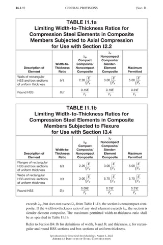
![16.1-93
Specification for Structural Steel Buildings, August 1, 2022
American Institute of Steel Construction
User Note: All current ASTM A500/A500M Grade C square HSS sections are
compact composite according to the limits of Table I1.1a and Table I1.1b, except
HSS7×7×1
/8, HSS8×8×1
/8, HSS10×10×3/16, HSS12×12×3/16, HSS14×14×1
/4,
HSS16×16×1
/4, HSS18×18×5/16, and HSS20×20×5/16, which are noncompact
composite for both axial compression and flexure, and HSS9×9×1
/8 and
HSS18×18×1
/4, which are slender-element composite for both axial compression
and flexure.
All current ASTM A1085/A1085M square HSS are compact composite except for
HSS8×8×1
/8, HSS 9×9×1
/8, HSS 12×12×3/16, HSS16×16×1
/4, HSS18×18×1
/4,
HSS18×18×5/16, and HSS 20×20×5/16, which are noncompact composite for
both axial compression and flexure.
All current ASTM A500/A500M Grade C round HSS sections are compact
composite according to the limits of Table I1.1a and Table I1.1b for both axial
compression and flexure, with the exception of HSS6.625×0.125,
HSS7.000×0.125, HSS9.625×0.188, HSS10.000×0.188,
HSS10.75×0.188, HSS12.750×0.188, HSS12.750×0.250,
HSS13.375×0.188, HSS13.375×0.250, HSS14.000×0.188,
HSS14.000×0.250, HSS16.000×0.250, HSS16.000×0.312,
HSS18.000×0.250, HSS18.000×0.313, HSS20.000×0.250,
HSS20.000×0.313, HSS20.000×0.375, HSS22.000×0.313,
HSS22.000×0.375, HSS24.000×0.313, HSS24.000×0.375,
HSS26.000×0.375, HSS26.000×0.500, HSS28.000×0.375, and
HSS28.000×0.500, which are noncompact composite for flexure, and
HSS26.000×0.313, which is noncompact for compression and flexure.
5. Stiffness for Calculation of Required Strengths
For the direct analysis method of design, the required strengths of encased composite
members, filled composite members, and composite plate shear walls shall be deter-
mined using the provisions of Section C2 and the following requirements:
(a)
The nominal flexural stiffness of encased and filled composite members subjected
to net compression shall be taken as the effective stiffness of the composite sec-
tion, (EI)eff, as defined in Section I2.
(b)
The nominal axial stiffness of encased and filled composite members subjected
to net compression shall be taken as the summation of the elastic axial stiffnesses
of each component.
(c)
The stiffness of encased and filled composite members subjected to net tension
shall be taken as the stiffness of the bare steel members in accordance with
Chapter C.
(d)
The stiffness reduction parameter, τb, shall be taken as 0.8 for encased and filled
composite members.
Sect. I1.] GENERAL PROVISIONS
Part 16.1 G-I (075-120).indd 93
Part 16.1 G-I (075-120).indd 93 2023-01-10 7:41 PM
2023-01-10 7:41 PM](https://image.slidesharecdn.com/aisc360-22specificationforstructuralsteelbuildings-231108145904-1b416cfe/85/AISC-360-22-Specification-for-Structural-Steel-Buildings-pdf-161-320.jpg)
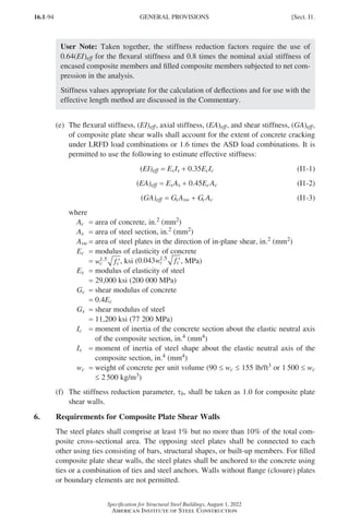
![16.1-95
Specification for Structural Steel Buildings, August 1, 2022
American Institute of Steel Construction
6a. Slenderness Requirement
The slenderness ratio of the plates, b t , shall be limited as follows:
b
t
E
Fy
≤1 2
. (I1-4)
where
b = largest clear distance between rows of steel anchors or ties, in. (mm)
t = thickness of plate, in. (mm)
6b. Tie Bar Requirement
Tie bars shall have spacing no greater than 1.0 times the wall thickness, tsc. The tie
bar spacing to plate thickness ratio, s t
t , shall be limited as follows:
s
t
E
t s
≤
+
1 0
2 1
.
α
(I1-5)
s
t
E
t s
≤
+
0 38
2 1
.
α
(I1-5M)
α = −
1 7 2
4
.
t
t
t
d
sc
tie
(I1-6)
where
dtie = effective diameter of the tie bar, in. (mm)
st = largest clear spacing of the ties, in. (mm)
t = thickness of plate, in. (mm)
tsc = thickness of composite plate shear wall, in. (mm)
I2. AXIAL FORCE
This section applies to encased composite members, filled composite members, and
composite plate shear walls subjected to axial force.
1. Encased Composite Members
1a. Limitations
For encased composite members, the following limitations shall be met:
(a)
The cross-sectional area of the steel core shall comprise at least 1% of the total
composite cross section.
(b)
Concrete encasement of the steel core shall be reinforced with continuous longi-
tudinal bars and transverse reinforcement consisting of ties, hoops, and/or spirals.
Detailing and placement of longitudinal reinforcement, including bar spacing
and concrete cover requirements, shall conform to ACI 318.
Transverse reinforcement where specified as ties or hoops shall consist of a
minimum of either a No. 3 (10 mm) bar spaced at a maximum of 12 in. (300 mm)
on center, or a No. 4 (13 mm) bar or larger spaced at a maximum of 16 in.
Sect. I2.] AXIAL FORCE
Part 16.1 G-I (075-120).indd 95
Part 16.1 G-I (075-120).indd 95 2023-01-10 7:41 PM
2023-01-10 7:41 PM](https://image.slidesharecdn.com/aisc360-22specificationforstructuralsteelbuildings-231108145904-1b416cfe/85/AISC-360-22-Specification-for-Structural-Steel-Buildings-pdf-163-320.jpg)
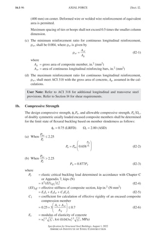
![16.1-97
Specification for Structural Steel Buildings, August 1, 2022
American Institute of Steel Construction
′
fc = specified compressive strength of concrete, ksi (MPa)
wc =
weight of concrete per unit volume (90 ≤ wc ≤ 155 lb/ft3 or 1500 ≤ wc ≤
2 500 kg/m3)
Es = modulus of elasticity of steel
= 29,000 ksi (200 000 MPa)
Ic =
moment of inertia of the concrete section about the elastic neutral axis of
the composite section, in.4 (mm4)
Is =
moment of inertia of steel shape about the elastic neutral axis of the com-
posite section, in.4 (mm4)
Isr =
moment of inertia of reinforcing bars about the elastic neutral axis of the
composite section, in.4 (mm4)
Lc = effective length of the member, in. (mm)
= KL
K = effective length factor
L = laterally unbraced length of the member, in. (mm)
Pno =
nominal axial compressive strength without consideration of length effects,
kips (N)
=
= + + ′
F A F A f A
y s ysr sr c c
0 85
. (I2-7)
Ac = area of concrete, in.2 (mm2)
As = cross-sectional area of structural steel section, in.2 (mm2)
Fy = specified minimum yield stress of structural steel section, ksi (MPa)
Fysr = specified minimum yield stress of reinforcing steel, ksi (MPa)
The available compressive strength need not be less than that determined for the bare
steel member in accordance with Chapter E.
1c. Tensile Strength
The available tensile strength of axially loaded encased composite members shall be
determined for the limit state of yielding as
Pn = FyAs + FysrAsr (I2-8)
φt = 0.90 (LRFD) Wt = 1.67 (ASD)
1d. Load Transfer
Load transfer requirements for encased composite members shall be determined in
accordance with Section I6.
1e. Detailing Requirements
For encased composite members, the following detailing requirements shall be met:
(a)
Clear spacing between the steel core and longitudinal reinforcing bars shall be a
minimum of 1.5 longitudinal reinforcing bar diameters, but not less than 1.5 in.
(38 mm).
(b)
If the composite cross section is built up from two or more encased steel shapes,
the shapes shall be interconnected with lacing, tie plates, or comparable com-
ponents to prevent buckling of individual shapes due to loads applied prior to
hardening of the concrete.
Sect. I2.] AXIAL FORCE
Part 16.1 G-I (075-120).indd 97
Part 16.1 G-I (075-120).indd 97 2023-01-10 7:41 PM
2023-01-10 7:41 PM](https://image.slidesharecdn.com/aisc360-22specificationforstructuralsteelbuildings-231108145904-1b416cfe/85/AISC-360-22-Specification-for-Structural-Steel-Buildings-pdf-165-320.jpg)
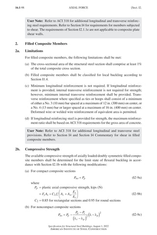
![16.1-99
Specification for Structural Steel Buildings, August 1, 2022
American Institute of Steel Construction
where
λp and λr are width-to-thickness ratios determined from Table I1.1a.
Pp is determined from Equation I2-9b.
Py = F A f A A
E
E
y s c c sr
s
c
+ ′ +
0 7
. (I2-9d)
(c) For slender composite sections
P F A f A A
E
E
no n s c c sr
s
c
= + ′ +
0 7
. (I2-9e)
where
the critical buckling stress for the structural steel section of filled composite
members, Fn, is determined as follows:
(1) For rectangular filled sections
F
E
n
s
=
9
2
λ
(I2-10)
(2) For round filled sections
F
F
D
t
F
E
n
y
y
s
=
0 72
0 2
.
.
(I2-11)
See Section I1.4 for definitions of maximum width-to-thickness ratio, λ;
width, D; and thickness, t, for rectangular and round HSS and box sections of
uniform thickness.
The effective stiffness of the composite section, ( )
EI eff , for all sections shall be
( )
EI eff = EsIs + EsIsr + C3EcIc (I2-12)
where
C3 =
coefficient for calculation of effective rigidity of a filled composite compres-
sion member
=
0 45 3 0 9
. .
+
+
≤
A A
A
s sr
g
(I2-13)
The available compressive strength need not be less than that determined for the bare
steel member in accordance with Chapter E.
2c. Tensile Strength
The available tensile strength of axially loaded filled composite members shall be
determined for the limit state of yielding as
Pn = AsFy + AsrFysr (I2-14)
φt = 0.90 (LRFD) Wt = 1.67 (ASD)
2d. Load Transfer
Load transfer requirements for filled composite members shall be determined in
accordance with Section I6.
Sect. I2.] AXIAL FORCE
Part 16.1 G-I (075-120).indd 99
Part 16.1 G-I (075-120).indd 99 2023-01-10 7:41 PM
2023-01-10 7:41 PM](https://image.slidesharecdn.com/aisc360-22specificationforstructuralsteelbuildings-231108145904-1b416cfe/85/AISC-360-22-Specification-for-Structural-Steel-Buildings-pdf-167-320.jpg)
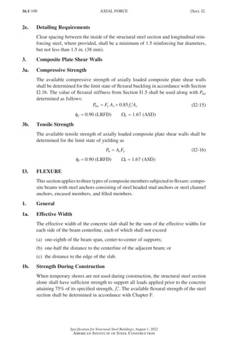
![16.1-101
Specification for Structural Steel Buildings, August 1, 2022
American Institute of Steel Construction
2. Composite Beams with Steel Headed Stud or Steel Channel Anchors
2a. Positive Flexural Strength
The design positive flexural strength, φbMn, and allowable positive flexural strength,
Mn b
Ω , shall be determined for the limit state of yielding as follows:
φb = 0.90 (LRFD) Wb = 1.67 (ASD)
(a) When h t E F
w y
≤ 3 76
.
Mn shall be determined from the plastic stress distribution on the composite
section for the limit state of yielding (plastic moment).
User Note: All current ASTM A6/A6M W, S, and HP shapes satisfy the limit
given in Section I3.2a(a) for Fy ≤ 70 ksi (485 MPa).
(b) When h t E F
w y
3 76
.
Mn shall be determined from the superposition of elastic stresses, considering the
effects of shoring, for the limit state of yielding (yield moment).
2b. Negative Flexural Strength
The available negative flexural strength shall be determined for the structural steel
section alone, in accordance with the requirements of Chapter F.
Alternatively, the available negative flexural strength shall be determined from the
plastic stress distribution for the composite section, for the limit state of yielding
(plastic moment), with
φb = 0.90 (LRFD) Wb = 1.67 (ASD)
provided that the following limitations are met:
(a) The steel beam is compact and is braced in accordance with Chapter F.
(b)
Steel headed stud or steel channel anchors connect the slab to the steel beam in
the negative moment region.
(c)
The slab longitudinal reinforcement parallel to the steel beam, within the effec-
tive width of the slab, meets the development length requirements.
User Note: To check compactness of a composite beam in negative flexure, Case
10 in Table B4.1b is appropriate to use for flanges, and Case 15 of Table B4.1b
is appropriate to use for webs.
2c. Composite Beams with Formed Steel Deck
1. General
The available flexural strength of composite construction consisting of con-
crete slabs on formed steel deck connected to steel beams shall be determined
Sect. I3.] FLEXURE
Part 16.1 G-I (075-120).indd 101
Part 16.1 G-I (075-120).indd 101 2023-01-10 7:41 PM
2023-01-10 7:41 PM](https://image.slidesharecdn.com/aisc360-22specificationforstructuralsteelbuildings-231108145904-1b416cfe/85/AISC-360-22-Specification-for-Structural-Steel-Buildings-pdf-169-320.jpg)
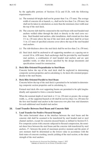
![16.1-103
Specification for Structural Steel Buildings, August 1, 2022
American Institute of Steel Construction
(a) Concrete crushing
′ = ′
V f A
c c
85
0. (I3-1a)
(b) Tensile yielding of the steel section
′=
V F A
y s (I3-1b)
(c) Shear strength of steel headed stud or steel channel anchors
′ =
V Qn
Σ (I3-1c)
where
Ac = area of concrete slab within effective width, in.2 (mm2)
As = cross-sectional area of structural steel section, in.2 (mm2)
ΣQn =
sum of nominal shear strengths of steel headed stud or steel channel
anchors between the point of maximum positive moment and the point
of zero moment, kips (N)
The effect of ductility (slip capacity) of the shear connection at the interface of
the concrete slab and the steel beam shall be considered.
2. Load Transfer for Negative Flexural Strength
In continuous composite beams where longitudinal reinforcing steel in the nega-
tive moment regions is considered to act compositely with the steel beam, the
total horizontal shear between the point of maximum negative moment and the
point of zero moment shall be determined as the lower value in accordance with
the following limit states:
(a) For the limit state of tensile yielding of the slab longitudinal reinforcement
′=
V F A
y s
Fysr Asr (I3-2a)
where
Asr =
area of developed longitudinal reinforcing steel within the effective
width of the concrete slab, in.2 (mm2)
Fysr = specified minimum yield stress of the reinforcing steel, ksi (MPa)
(b)
For the limit state of shear strength of steel headed stud or steel channel anchors
′ =
V Qn
Σ (I3-2b)
3. Encased Composite Members
3a. Limitations
For encased composite members, the following limitations shall be met:
(a)
The available flexural strength of concrete-encased members shall be determined
as follows:
φb = 0.90 (LRFD) Wb = 1.67 (ASD)
The nominal flexural strength, Mn, shall be determined using one of the follow-
ing methods:
(1)
The superposition of elastic stresses on the composite section, considering
the effects of shoring for the limit state of yielding (yield moment).
Sect. I3.] FLEXURE
Part 16.1 G-I (075-120).indd 103
Part 16.1 G-I (075-120).indd 103 2023-01-10 7:41 PM
2023-01-10 7:41 PM](https://image.slidesharecdn.com/aisc360-22specificationforstructuralsteelbuildings-231108145904-1b416cfe/85/AISC-360-22-Specification-for-Structural-Steel-Buildings-pdf-171-320.jpg)
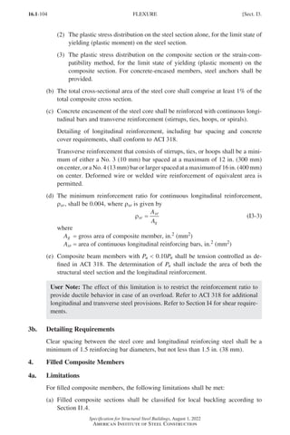
![16.1-105
Specification for Structural Steel Buildings, August 1, 2022
American Institute of Steel Construction
(b)
The total cross-sectional area of the structural steel section shall comprise at least
1% of the total composite cross section.
(c) Longitudinal reinforcement is not required.
Where longitudinal reinforcement is provided, the minimum reinforcement
ratio for continuous longitudinal reinforcement, ρsr, shall be 0.004, where ρsr
is given by
ρsr
sr
g
A
A
= (I3-4)
If longitudinal reinforcement is provided, internal transverse reinforcement is
not required for strength; however, minimum internal transverse reinforcement
shall be provided. The minimum transverse reinforcement shall be hoops and
ties or hoops alone consisting of a minimum of either a No. 3 (10 mm) bar
spaced at a maximum of 12 in. (300 mm) on center, or a No. 4 (13 mm) bar or
larger spaced at a maximum of 16 in. (400 mm) on center. Deformed wire or
welded wire reinforcement of equivalent area is permitted.
(d)
Composite beam members with Pu 0.10Pn shall be tension controlled as de-
fined in ACI 318. The determination of Pn shall include the area of both the
structural steel section and the longitudinal reinforcement.
User Note: The effect of this limitation is to restrict the longitudinal reinforce-
ment ratio to provide ductile behavior in case of an overload. Refer to ACI 318
for additional provisions for the longitudinal and transverse steel reinforcement.
Refer to Section I4 for shear requirements. The limitations and requirements of
Section I3.4a are not applicable to composite plate shear walls.
4b. Flexural Strength
The available flexural strength of filled composite members shall be determined as
follows:
φb = 0.90 (LRFD) Wb = 1.67 (ASD)
The nominal flexural strength, Mn, shall be determined as follows:
(a) For compact composite sections
Mn = Mp (I3-5a)
where
Mp =
moment corresponding to plastic stress distribution over the composite
cross section, kip-in. (N-mm)
(b) For noncompact composite sections
M M M M
n p p y
p
r p
= ( )
−
−
– –
λ λ
λ λ
(I3-5b)
where
l, lp, and lr are width-to-thickness ratios determined from Table I1.1b.
Sect. I3.] FLEXURE
Part 16.1 G-I (075-120).indd 105
Part 16.1 G-I (075-120).indd 105 2023-01-10 7:41 PM
2023-01-10 7:41 PM](https://image.slidesharecdn.com/aisc360-22specificationforstructuralsteelbuildings-231108145904-1b416cfe/85/AISC-360-22-Specification-for-Structural-Steel-Buildings-pdf-173-320.jpg)
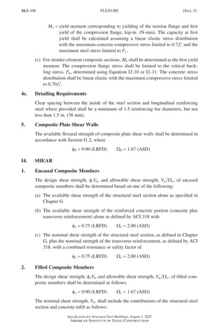
![16.1-107
Specification for Structural Steel Buildings, August 1, 2022
American Institute of Steel Construction
V A F K A f
n v y c c c
= + ′
0 6 0 06
. . (I4-1)
where
Av =
shear area of the steel portion of a composite member. The shear area for a
round section is equal to 2As π, and for a rectangular section is equal to the
sum of the area of webs in the direction of in-plane shear, in.2 (mm2)
Ac = area of concrete infill, in.2 (mm2)
Kc =
1 for members with shear span-to-depth, M V d
u u
( ) , greater than or equal
to 0.7, where Mu and Vu are equal to the maximum required flexural and
shear strengths, respectively, along the member length, and d is equal to the
member depth in the direction of bending
=
10 for members with rectangular compact composite cross sections and
M V d
u u
( ) less than 0.5
=
9 for members with round compact composite cross sections and M V d
u u
( )
less than 0.5
=
1 for members having other than compact composite cross sections, for all
values of M V d
u u
( )
Linear interpolation between these Kc values shall be used for members with com-
pact composite cross sections and with M V d
u u
( ) between 0.5 and 0.7.
User Note: For most members, Kc will be equal to 1.0. Low shear span-to-depth
ratios may occur in connection design (panel zones) or other special situations,
for which higher values of Kc ( 1.0) are more appropriate.
3. Composite Beams with Formed Steel Deck
The available shear strength of composite beams with steel headed stud or steel chan-
nel anchors shall be determined based upon the properties of the steel section alone
in accordance with Chapter G.
4. Composite Plate Shear Walls
The design in-plane shear strength, φvVn, and allowable shear strength, Vn v
Ω , of
composite plate shear walls shall be determined as follows:
φv = 0.90 (LRFD) Wv = 1.67 (ASD)
The nominal shear strength, Vn, shall account for the contributions of the structural
steel section and concrete infill as follows:
V
K K
K K
A F
n
s sc
s sc
sw y
=
+
+
3 2 2
(I4-2)
where
Asw = area of steel plates in the direction of in-plane shear, in.2 (mm2)
Ks = GsAsw (I4-3)
Gs = shear modulus of steel
=
11,200 ksi (77 200 MPa)
Ksc =
0 7
4
. E A E A
E A E A
c c s sw
s sw c c
( )( )
+
(I4-4)
Sect. I4.] SHEAR
Part 16.1 G-I (075-120).indd 107
Part 16.1 G-I (075-120).indd 107 2023-01-10 7:41 PM
2023-01-10 7:41 PM](https://image.slidesharecdn.com/aisc360-22specificationforstructuralsteelbuildings-231108145904-1b416cfe/85/AISC-360-22-Specification-for-Structural-Steel-Buildings-pdf-175-320.jpg)
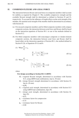
![16.1-109
Specification for Structural Steel Buildings, August 1, 2022
American Institute of Steel Construction
For design according to Section B3.2 (ASD)
Mr =
required flexural strength, determined in accordance with Section
I1.5, using ASD load combinations, kip-in. (N-mm)
Mc =
allowable flexural strength, determined in accordance with Section I3,
kip-in. (N-mm)
=
Mn b
Ω
Pr =
required axial strength, determined in accordance with Section I1.5
using ASD load combinations, kips (N)
Pc =
allowable axial strength, determined in accordance with Section I2,
kips (N)
=
Pn c
Ω
Wb = safety factor for flexure
= 1.67
Wc = safety factor for compression
= 2.00
cm and cp are determined from Table I5.1
csr =
c
A F A F
A f
sr
s y sr yr
c c
=
+
′
(I5-2)
(c)
For composite plate shear walls, the interaction between axial force and flexure
shall be based on the methods defined in Section I1.2.
I6. LOAD TRANSFER
1. General Requirements
When external forces are applied to an axially loaded encased or filled composite
member, the introduction of force to the member and the transfer of longitudinal
shear within the member shall be assessed in accordance with the requirements for
force allocation presented in this section.
The available strength of the applicable force transfer mechanisms as determined
in accordance with Section I6.3 shall equal or exceed the required shear force to be
transferred, ′
Vr , as determined in accordance with Section I6.2. Force transfer mecha-
nisms shall be located within the load transfer region as determined in accordance
with Section I6.4.
2. Force Allocation
Force allocation shall be determined based upon the distribution of external force in
accordance with the following requirements.
User Note: Bearing strength provisions for externally applied forces are provided
in Section J8. For filled composite members, the term A A
2 1 in Equation J8-2
may be taken equal to 2.0 due to confinement effects.
Sect. I6.] LOAD TRANSFER
Part 16.1 G-I (075-120).indd 109
Part 16.1 G-I (075-120).indd 109 2023-01-10 7:41 PM
2023-01-10 7:41 PM](https://image.slidesharecdn.com/aisc360-22specificationforstructuralsteelbuildings-231108145904-1b416cfe/85/AISC-360-22-Specification-for-Structural-Steel-Buildings-pdf-177-320.jpg)
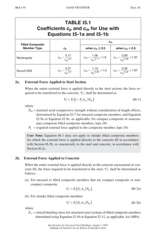
![16.1-111
Specification for Structural Steel Buildings, August 1, 2022
American Institute of Steel Construction
Pno =
nominal axial compressive strength without consideration of length effects,
determined by Equation I2-7 for encased composite members, and Equa-
tion I2-9a, Equation I2-9c, or Equation I2-9e for filled composite members,
kips (N)
2c. External Force Applied Concurrently to Steel and Concrete
When the external force is applied concurrently to the steel section and concrete
encasement or concrete fill, ′
Vr shall be determined as the force required to establish
equilibrium of the cross section.
User Note: The Commentary provides an acceptable method of determining the
longitudinal shear force required for equilibrium of the cross section.
3. Force Transfer Mechanisms
The available strength of the force transfer mechanisms of direct bond interaction,
shear connection, and direct bearing shall be determined in accordance with this sec-
tion. Use of the force transfer mechanism providing the largest nominal strength is
permitted. Force transfer mechanisms shall not be superimposed.
The force transfer mechanism of direct bond interaction shall not be used for encased
composite members or for filled composite members where bond failure would result
in uncontrolled slip.
3a. Direct Bearing
Where force is transferred in an encased or filled composite member by direct bear-
ing from internal bearing mechanisms, the available bearing strength of the concrete
for the limit state of concrete crushing shall be determined as
R f A
n c
= ′
1 7 1
. (I6-3)
φB = 0.65 (LRFD) ΩB = 2.31 (ASD)
where
A1 = loaded area of concrete, in.2 (mm2)
User Note: An example of force transfer via an internal bearing mechanism is the
use of internal steel plates within a filled composite member.
3b. Shear Connection
Where force is transferred in an encased or filled composite member by shear con-
nectors, the available shear strength of steel headed stud or steel channel anchors
shall be determined as
Rc = SQcv (I6-4)
where
SQcv =
sum of available shear strengths, φvQnv (LRFD) or Qnv Ωv (ASD), as ap-
plicable, of steel headed stud or steel channel anchors, determined in
accordance with Section I8.3a or Section I8.3d, respectively, placed within
the load introduction length as defined in Section I6.4, kips (N)
Sect. I6.] LOAD TRANSFER
Part 16.1 G-I (075-120).indd 111
Part 16.1 G-I (075-120).indd 111 2023-01-10 7:41 PM
2023-01-10 7:41 PM](https://image.slidesharecdn.com/aisc360-22specificationforstructuralsteelbuildings-231108145904-1b416cfe/85/AISC-360-22-Specification-for-Structural-Steel-Buildings-pdf-179-320.jpg)
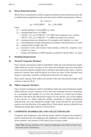
![16.1-113
Specification for Structural Steel Buildings, August 1, 2022
American Institute of Steel Construction
I8. STEEL ANCHORS
1. General
The diameter of a steel headed stud anchor, dsa, shall be w in. (19 mm) or less, except
where anchors are utilized solely for shear transfer in solid slabs, in which case,
d-in.- (22-mm-) and 1-in.- (25-mm-) diameter anchors are permitted. Additionally,
dsa shall not be greater than 2.5 times the thickness of the base metal to which it is
welded, unless it is welded to a flange directly over a web.
Section I8.2 applies to a composite flexural member where steel anchors are embed-
ded in a solid concrete slab or in a slab cast on a formed steel deck. Section I8.3
applies to all other cases.
2. Steel Anchors in Composite Beams
The length of steel headed stud anchors shall not be less than four stud diameters
from the base of the steel headed stud anchor to the top of the stud head after instal-
lation.
2a. Strength of Steel Headed Stud Anchors
The nominal shear strength of one steel headed stud anchor embedded in a solid
concrete slab or in a composite slab with decking shall be determined as follows:
Q A f E R R A F
n sa c c g p sa u
= ′ ≤
0 5
. (I8-1)
where
Asa = cross-sectional area of steel headed stud anchor, in.2 (mm2)
Ec = modulus of elasticity of concrete
=
w f
c c
1 5
.
′ , ksi (0 043 1 5
. .
w f
c c′, MPa)
Fu =
specified minimum tensile strength of a steel headed stud anchor, ksi
(MPa)
Rg = 1.0 for the following:
(a)
One steel headed stud anchor welded in a steel deck rib with the deck
oriented perpendicular to the steel shape
(b)
Any number of steel headed stud anchors welded in a row directly to
the steel shape
(c)
Any number of steel headed stud anchors welded in a row through
steel deck with the deck oriented parallel to the steel shape and the
ratio of the average rib width to rib depth ≥ 1.5
=
0.85 for the following:
(a)
Two steel headed stud anchors welded in a steel deck rib with the
deck oriented perpendicular to the steel shape
(b)
One steel headed stud anchor welded through steel deck with the
deck oriented parallel to the steel shape and the ratio of the average
rib width to rib depth 1.5
=
0.7 for three or more steel headed stud anchors welded in a steel deck rib
with the deck oriented perpendicular to the steel shape
Rp = 0.75 for the following:
(a) Steel headed stud anchors welded directly to the steel shape
Sect. I8.] STEEL ANCHORS
Part 16.1 G-I (075-120).indd 113
Part 16.1 G-I (075-120).indd 113 2023-01-10 7:41 PM
2023-01-10 7:41 PM](https://image.slidesharecdn.com/aisc360-22specificationforstructuralsteelbuildings-231108145904-1b416cfe/85/AISC-360-22-Specification-for-Structural-Steel-Buildings-pdf-181-320.jpg)
![16.1-114
Specification for Structural Steel Buildings, August 1, 2022
American Institute of Steel Construction
(b)
Steel headed stud anchors welded in a composite slab with the deck
oriented perpendicular to the beam and emid-ht ≥ 2 in. (50 mm)
(c)
Steel headed stud anchors welded through steel deck, or steel sheet
used as girder filler material and embedded in a composite slab with
the deck oriented parallel to the beam
=
0.6 for steel headed stud anchors welded in a composite slab with deck
oriented perpendicular to the beam and emid-ht 2 in. (50 mm)
emid-ht =
distance from the edge of steel headed stud anchor shank to the steel
deck web, measured at mid-height of the deck rib, and in the load bearing
direction of the steel headed stud anchor (in other words, in the direction
of maximum moment for a simply supported beam), in. (mm)
User Note: The table below presents values for Rg and Rp for several cases.
Available strengths for steel headed stud anchors can be found in the AISC
Steel Construction Manual.
Condition Rg Rp
No decking 1.0 0.75
Decking oriented parallel to the steel shape
w
h
r
r
≥ 1 5
.
w
h
r
r
1 5
.
1.0
0.85[a]
0.75
0.75
Decking oriented perpendicular to the steel
shape
Number of steel headed stud anchors
occupying the same decking rib:
1
2
3 or more
1.0
0.85
0.7
0.6[b]
0.6[b]
0.6[b]
hr = nominal rib height, in. (mm)
wr = average width of concrete rib or haunch (as defined in Section I3.2c), in. (mm)
[a]For a single steel headed stud anchor
[b]This value may be increased to 0.75 when emid-ht ≥ 2 in. (50 mm).
2b. Strength of Steel Channel Anchors
The nominal shear strength of one hot-rolled channel anchor embedded in a solid
concrete slab shall be determined as
Q t t l f E
n f w a c c
= + ′
0 3 0 5
. ( . ) (I8-2)
where
la = length of channel anchor, in. (mm)
tf = thickness of channel anchor flange, in. (mm)
tw = thickness of channel anchor web, in. (mm)
The strength of the channel anchor shall be developed by welding the channel to the
beam flange for a force equal to Qn, considering eccentricity on the anchor.
STEEL ANCHORS [Sect. I8.
Part 16.1 G-I (075-120).indd 114
Part 16.1 G-I (075-120).indd 114 2023-01-11 9:35 AM
2023-01-11 9:35 AM](https://image.slidesharecdn.com/aisc360-22specificationforstructuralsteelbuildings-231108145904-1b416cfe/85/AISC-360-22-Specification-for-Structural-Steel-Buildings-pdf-182-320.jpg)
![16.1-115
Specification for Structural Steel Buildings, August 1, 2022
American Institute of Steel Construction
2c. Required Number of Steel Anchors
The number of anchors required between the section of maximum bending moment,
positive or negative, and the adjacent section of zero moment shall be equal to the
horizontal shear as determined in Sections I3.2d.1 and I3.2d.2 divided by the nomi-
nal shear strength of one steel anchor as determined from Section I8.2a or Section
I8.2b. The number of steel anchors required between any concentrated load and the
nearest point of zero moment shall be sufficient to develop the maximum moment
required at the concentrated load point.
2d. Detailing Requirements
Steel anchors in composite beams shall meet the following requirements:
(a)
Steel anchors required on each side of the point of maximum bending moment,
positive or negative, shall be distributed uniformly between that point and the
adjacent points of zero moment, unless specified otherwise on the design docu-
ments and specifications issued for construction.
(b)
Steel anchors shall have at least 1 in. (25 mm) of lateral concrete cover in the
direction perpendicular to the shear force, except for anchors installed in the ribs
of formed steel decks.
(c)
The minimum distance from the center of a steel anchor to a free edge in the
direction of the shear force shall be 8 in. (200 mm) if normal weight concrete is
used and 10 in. (250 mm) if lightweight concrete is used. The provisions of ACI
318, Chapter 17, are permitted to be used in lieu of these values.
(d)
Minimum center-to-center spacing of steel headed stud anchors shall be four
diameters in any direction. For composite beams that do not contain anchors
located within formed steel deck oriented perpendicular to the beam span, an
additional minimum spacing limit of six diameters along the longitudinal axis of
the beam shall apply.
(e)
The maximum center-to-center spacing of steel anchors shall not exceed eight
times the total slab thickness or 36 in. (900 mm).
3. Steel Anchors in Composite Components
This section shall apply to the design of cast-in-place steel headed stud anchors and
steel channel anchors in composite components.
The provisions of the applicable building code or ACI 318, Chapter 17, are permitted
to be used in lieu of the provisions in this section.
User Note: The steel headed stud anchor strength provisions in this section are
applicable to anchors located primarily in the load transfer (connection) region
of composite columns and beam-columns, concrete-encased and filled composite
beams, composite coupling beams, and composite walls, where the steel and
concrete are working compositely within a member. They are not intended for
hybrid construction where the steel and concrete are not working compositely,
such as with embed plates.
Sect. I8.] STEEL ANCHORS
Part 16.1 G-I (075-120).indd 115
Part 16.1 G-I (075-120).indd 115 2023-01-10 7:41 PM
2023-01-10 7:41 PM](https://image.slidesharecdn.com/aisc360-22specificationforstructuralsteelbuildings-231108145904-1b416cfe/85/AISC-360-22-Specification-for-Structural-Steel-Buildings-pdf-183-320.jpg)
![16.1-116
Specification for Structural Steel Buildings, August 1, 2022
American Institute of Steel Construction
Section I8.2 specifies the strength of steel anchors embedded in a solid concrete
slab or in a concrete slab with formed steel deck in a composite beam.
Limit states for the steel shank of the anchor and for concrete breakout in shear
are covered directly in this section. Additionally, the spacing and dimensional
limitations provided in these provisions preclude the limit states of concrete
pryout for anchors loaded in shear and concrete breakout for anchors loaded in
tension as defined by ACI 318, Chapter 17.
For normal weight concrete: Steel headed stud anchors subjected to shear only shall
not be less than five stud diameters in length from the base of the steel headed stud
to the top of the stud head after installation. Steel headed stud anchors subjected to
tension or interaction of shear and tension shall not be less than eight stud diameters
in length from the base of the stud to the top of the stud head after installation.
For lightweight concrete: Steel headed stud anchors subjected to shear only shall not
be less than seven stud diameters in length from the base of the steel headed stud
to the top of the stud head after installation. Steel headed stud anchors subjected to
tension shall not be less than ten stud diameters in length from the base of the stud to
the top of the stud head after installation. The nominal strength of steel headed stud
anchors subjected to interaction of shear and tension for lightweight concrete shall
be determined as stipulated by the applicable building code or ACI 318, Chapter 17.
Steel headed stud anchors subjected to tension or interaction of shear and tension
shall have a diameter of the head greater than or equal to 1.6 times the diameter of
the shank.
User Note: The following table presents values of minimum steel headed stud
anchor h d ratios for each condition covered in this Specification.
Loading
Condition
Normal Weight
Concrete
Lightweight
Concrete
Shear h dsa ≥ 5 h dsa ≥ 7
Tension h dsa ≥ 8 h dsa ≥ 10
Shear and tension h dsa ≥ 8 NA[a]
h dsa ≥ 5
=
ratio of steel headed stud anchor shank length to the top of the stud head-to-shank
diameter.
[a]
Refer to ACI 318, Chapter 17, for the calculation of interaction effects of anchors embedded
in lightweight concrete.
3a. Shear Strength of Steel Headed Stud Anchors in Composite Components
Where concrete breakout strength in shear is not an applicable limit state, the design
shear strength, φvQnv, and allowable shear strength, Qnv v
Ω , of one steel headed stud
anchor shall be determined as
STEEL ANCHORS [Sect. I8.
Part 16.1 G-I (075-120).indd 116
Part 16.1 G-I (075-120).indd 116 2023-01-10 7:41 PM
2023-01-10 7:41 PM](https://image.slidesharecdn.com/aisc360-22specificationforstructuralsteelbuildings-231108145904-1b416cfe/85/AISC-360-22-Specification-for-Structural-Steel-Buildings-pdf-184-320.jpg)
![16.1-117
Specification for Structural Steel Buildings, August 1, 2022
American Institute of Steel Construction
Qnv = FuAsa (I8-3)
fv = 0.65 (LRFD) Wv = 2.31 (ASD)
where
Asa = cross-sectional area of a steel headed stud anchor, in.2 (mm2)
Fu = specified minimum tensile strength of a steel headed stud anchor, ksi (MPa)
Qnv = nominal shear strength of a steel headed stud anchor, kips (N)
Where concrete breakout strength in shear is an applicable limit state, the available
shear strength of one steel headed stud anchor shall be determined by one of the
following:
(a)
Where anchor reinforcement is developed in accordance with ACI 318 on both
sides of the concrete breakout surface for the steel headed stud anchor, the mini-
mum of the steel nominal shear strength from Equation I8-3 and the nominal
strength of the anchor reinforcement shall be used for the nominal shear strength,
Qnv, of the steel headed stud anchor.
(b) As stipulated by the applicable building code or ACI 318, Chapter 17.
User Note: If concrete breakout strength in shear is an applicable limit state (for
example, where the breakout prism is not restrained by an adjacent steel plate,
flange, or web), appropriate anchor reinforcement is required for the provisions
of this section to be used. Alternatively, the provisions of the applicable building
code or ACI 318, Chapter 17, may be used.
3b. Tensile Strength of Steel Headed Stud Anchors in Composite Components
Where the distance from the center of an anchor to a free edge of concrete in the
direction perpendicular to the height of the steel headed stud anchor is greater than
or equal to 1.5 times the height of the steel headed stud anchor measured to the top
of the stud head, and where the center-to-center spacing of steel headed stud anchors
is greater than or equal to three times the height of the steel headed stud anchor mea-
sured to the top of the stud head, the available tensile strength of one steel headed
stud anchor shall be determined as
Qnt = FuAsa (I8-4)
ft = 0.75 (LRFD) Wt = 2.00 (ASD)
where
Qnt = nominal tensile strength of steel headed stud anchor, kips (N)
Where the distance from the center of an anchor to a free edge of concrete in the
direction perpendicular to the height of the steel headed stud anchor is less than 1.5
times the height of the steel headed stud anchor measured to the top of the stud head,
or where the center-to-center spacing of steel headed stud anchors is less than three
times the height of the steel headed stud anchor measured to the top of the stud head,
the nominal tensile strength of one steel headed stud anchor shall be determined by
one of the following:
Sect. I8.] STEEL ANCHORS
Part 16.1 G-I (075-120).indd 117
Part 16.1 G-I (075-120).indd 117 2023-01-10 7:41 PM
2023-01-10 7:41 PM](https://image.slidesharecdn.com/aisc360-22specificationforstructuralsteelbuildings-231108145904-1b416cfe/85/AISC-360-22-Specification-for-Structural-Steel-Buildings-pdf-185-320.jpg)
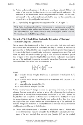
![16.1-119
Specification for Structural Steel Buildings, August 1, 2022
American Institute of Steel Construction
strength of the anchor reinforcement shall be used for the nominal shear strength,
Qnv, of the steel headed stud anchor, and the minimum of the steel nominal
tensile strength from Equation I8-4 and the nominal strength of the anchor rein-
forcement shall be used for the nominal tensile strength, Qnt, of the steel headed
stud anchor for use in Equation I8-5.
(b) As stipulated by the applicable building code or ACI 318, Chapter 17.
3d. Shear Strength of Steel Channel Anchors in Composite Components
The available shear strength of steel channel anchors shall be based on the provisions
of Section I8.2b with the following resistance factor and safety factor:
fv = 0.75 (LRFD) Wv = 2.00 (ASD)
3e. Detailing Requirements in Composite Components
Steel anchors in composite components shall meet the following requirements:
(a)
Minimum concrete cover to steel anchors shall be in accordance with ACI 318
provisions for concrete protection of headed shear stud reinforcement.
(b)
Minimum center-to-center spacing of steel headed stud anchors shall be four
diameters in any direction.
(c)
The maximum center-to-center spacing of steel headed stud anchors shall not ex-
ceed 32 times the shank diameter.
(d)
The maximum center-to-center spacing of steel channel anchors shall be 24 in.
(600 mm).
User Note: Detailing requirements provided in this section are absolute limits.
See Sections I8.3a, I8.3b, and I8.3c for additional limitations required to preclude
edge and group effect considerations.
4. Performance-Based Alternative for the Design of Shear Connection
In lieu of shear connection prescribed by, and the corresponding strength determined
in accordance with, Sections I8.1 and I8.2, it is permitted to use an alternate form
of shear connection and determine its strength through testing, provided its perfor-
mance requirements are established in accordance with Sections I8.4a through I8.4d
and satisfy the approval requirements of the authority having jurisdiction. The geo-
metric limitations of Sections I3.2c, I8.1, and I8.2 do not apply to the performance
evaluated by Section I8.4.
4a. Test Standard
Shear connection strength, slip capacity, and stiffness shall be established in accor-
dance with AISI S923. An alternative test protocol may be used in the evaluation
when approved by the authority having jurisdiction.
Sect. I8.] STEEL ANCHORS
Part 16.1 G-I (075-120).indd 119
Part 16.1 G-I (075-120).indd 119 2023-01-29 11:54 AM
2023-01-29 11:54 AM](https://image.slidesharecdn.com/aisc360-22specificationforstructuralsteelbuildings-231108145904-1b416cfe/85/AISC-360-22-Specification-for-Structural-Steel-Buildings-pdf-187-320.jpg)
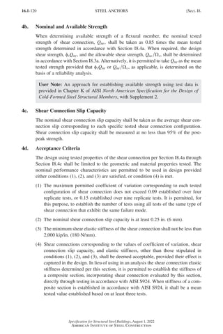
![16.1-123
Specification for Structural Steel Buildings, August 1, 2022
American Institute of Steel Construction
6. Weld Access Holes
Weld access holes shall meet the following requirements:
(a)
All weld access holes required to facilitate welding operations shall be detailed
to provide room for weld backing as needed.
(b)
The access hole shall have a length from the toe of the weld preparation not less
than 12 times the thickness of the material in which the hole is made, nor less
than 12 in. (38 mm).
(c)
The access hole shall have a height not less than the thickness of the material
with the access hole, nor less than w in. (19 mm), nor does it need to exceed
2 in. (50 mm).
(d)
For sections that are rolled or welded prior to cutting, the edge of the web shall
be sloped or curved from the surface of the flange to the reentrant surface of the
access hole.
(e)
In hot-rolled shapes, and built-up shapes with CJP groove welds that join the
web-to-flange, weld access holes shall be free of notches and sharp reentrant
corners.
(f)
No arc of the weld access hole shall have a radius less than a in. (10 mm).
(g)
In built-up shapes with fillet or partial-joint-penetration (PJP) groove welds
that join the web-to-flange, weld access holes shall be free of notches and sharp
reentrant corners.
(h)
The access hole is permitted to terminate perpendicular to the flange, providing
the weld is terminated at least a distance equal to the weld size away from the
access hole.
(i)
For heavy shapes, as defined in Sections A3.1d and A3.1e, the thermally cut
surfaces of weld access holes shall be ground to bright metal.
(j)
If the curved transition portion of weld access holes is formed by predrilled or
sawed holes, that portion of the access hole need not be ground.
7. Placement of Welds and Bolts
Groups of welds or bolts at the ends of any member that transmit axial force into
that member shall be sized so that the center of gravity of the group coincides with
the center of gravity of the member, unless provision is made for the eccentricity.
The foregoing provision is not applicable to end connections of single-angle, double-
angle, and similar members.
8. Bolts in Combination with Welds
Bolts shall not be considered as sharing the load in combination with welds, except
in the design of shear connections on a common faying surface where strain compat-
ibility between the bolts and welds is considered.
It is permitted to determine the available strength, φRn and Rn Ω, as applicable, of a
joint combining the strengths of high-strength bolts and longitudinal fillet welds as
Sect. J1.] GENERAL PROVISIONS
Part 16.1 J-N (121-194).indd 123
Part 16.1 J-N (121-194).indd 123 2023-01-10 8:06 PM
2023-01-10 8:06 PM](https://image.slidesharecdn.com/aisc360-22specificationforstructuralsteelbuildings-231108145904-1b416cfe/85/AISC-360-22-Specification-for-Structural-Steel-Buildings-pdf-191-320.jpg)
![16.1-125
Specification for Structural Steel Buildings, August 1, 2022
American Institute of Steel Construction
TABLE J2.1
Effective Throat of
Partial-Joint-Penetration Groove Welds
Welding Process
Welding Position
F (flat),
H (horizontal),
V (vertical),
OH (overhead)
Groove Type
(AWS D1.1,
Figure 5.2) Effective Throat
Shielded metal arc (SMAW)
All
J or U groove
60° V depth of groove
Gas metal arc (GMAW)
Flux cored arc (FCAW)
Submerged arc (SAW) F
J or U groove
60° bevel or V
Gas metal arc (GMAW)
Flux cored arc (FCAW)
F, H 45° bevel depth of groove
Shielded metal arc (SMAW) All
45° bevel
depth of groove
minus 1
/8 in.
(3 mm)
Gas metal arc (GMAW)
Flux cored arc (FCAW)
V, OH
1. Groove Welds
1a. Effective Area
The effective area of groove welds shall be taken as the length of the weld times the
effective throat.
The effective throat of a CJP groove weld shall be the thickness of the thinner part
joined.
When filled flush to the surface, the effective weld throat for a PJP groove weld
shall be as given in Table J2.1 and the effective weld throat for a flare groove weld
shall be as given in Table J2.2. The effective throat of a PJP groove weld or flare
groove weld filled less than flush shall be as shown in Table J2.1 or Table J2.2, less
the greatest perpendicular dimension measured from a line flush to the base metal
surface to the weld surface.
User Note: The effective throat of a PJP groove weld is dependent on the pro-
cess used and the weld position. The design documents should either indicate the
effective throat required or the weld strength required, and the fabricator should
detail the joint based on the weld process and position to be used to weld the joint.
For PJP groove welds, effective throats larger than those for prequalified PJP groove
welds in AWS D1.1/D1.1M, Figure 5.2, and flare groove welds in Table J2.2 are
permitted for a given welding procedure specification (WPS), provided the fabricator
establishes by testing the consistent production of such larger effective throats. Testing
shall consist of sectioning the weld normal to its axis, at mid-length, and at termi-
nal ends. Such sectioning shall be made on a number of combinations of material
Sect. J2.] WELDS AND WELDED JOINTS
Part 16.1 J-N (121-194).indd 125
Part 16.1 J-N (121-194).indd 125 2023-01-10 8:06 PM
2023-01-10 8:06 PM](https://image.slidesharecdn.com/aisc360-22specificationforstructuralsteelbuildings-231108145904-1b416cfe/85/AISC-360-22-Specification-for-Structural-Steel-Buildings-pdf-193-320.jpg)
![16.1-126
Specification for Structural Steel Buildings, August 1, 2022
American Institute of Steel Construction
TABLE J2.2
Effective Throat of
Flare Groove Welds
Welding Process Flare-Bevel-Groove[a] Flare-V-Groove
GMAW and FCAW-G 5
/8R 3
/4R
SMAW and FCAW-S 5
/16R 5
/8R
SAW 5
/16R 1
/2R
R =
radius of joint surface (is permitted to be assumed equal to 2t for HSS, where t is the design wall thick-
ness), in. (mm)
[a]For flare-bevel-groove with R 3
/8 in. (10 mm), use only reinforcing fillet weld on filled flush joint.
TABLE J2.3
Minimum Effective Throat of
Partial-Joint-Penetration Groove Welds
Material Thickness of
Thinner Part Joined, in. (mm)
Minimum Effective
Throat,[a] in. (mm)
To 1
/4 (6) inclusive
Over 1
/4 (6) to 1
/2 (13)
Over 1
/2 (13) to 3
/4 (19)
Over 3
/4 (19) to 11
/2 (38)
Over 11
/2 (38) to 21
/4 (57)
Over 21
/4 (57) to 6 (150)
Over 6 (150)
1
/8 (3)
3
/16 (5)
1
/4 (6)
5
/16 (8)
3
/8 (10)
1
/2 (13)
5
/8 (16)
[a]See Table J2.1.
sizes representative of the range to be used in the fabrication. During production of
welds with increased effective throats, single pass welds and the root pass of multi-
pass welds shall be made using a mechanized, automatic, or robotic process, with no
decrease in current or increase in travel speed from that used for testing.
1b. Limitations
The minimum effective throat of a partial-joint-penetration groove weld shall not be
less than the size required to transmit calculated forces nor the size shown in Table
J2.3. Minimum weld size is determined by the thinner of the two parts joined.
2. Fillet Welds
2a. Effective Area
The effective area of a fillet weld shall be the effective length multiplied by the
effective throat. The effective throat of a fillet weld shall be the shortest distance
from the root to the face of the diagrammatic weld. An increase in effective throat is
permitted if consistent penetration beyond the root of the diagrammatic weld is dem-
onstrated by tests using a given welding procedure specification (WPS), provided
the fabricator establishes by testing the consistent production of such larger effective
throat. Testing shall consist of sectioning the weld normal to its axis at mid-length
WELDS AND WELDED JOINTS [Sect. J2.
Part 16.1 J-N (121-194).indd 126
Part 16.1 J-N (121-194).indd 126 2023-01-10 8:06 PM
2023-01-10 8:06 PM](https://image.slidesharecdn.com/aisc360-22specificationforstructuralsteelbuildings-231108145904-1b416cfe/85/AISC-360-22-Specification-for-Structural-Steel-Buildings-pdf-194-320.jpg)
![16.1-127
Specification for Structural Steel Buildings, August 1, 2022
American Institute of Steel Construction
and terminal ends. During production, single pass welds and the root pass of multi-
pass welds shall be made using a mechanized, automatic, or robotic process with no
decrease in current or increase in travel speed from that used for testing.
For fillet welds in holes and slots, the effective length shall be the length of the
centerline of the weld along the center of the plane through the throat. In the case
of overlapping fillets, the effective area shall not exceed the nominal cross-sectional
area of the hole or slot in the plane of the faying surface.
2b. Limitations
Fillet welds shall meet the following limitations:
(a)
The minimum size of fillet welds shall be not less than the size required to trans-
mit calculated forces nor the size as shown in Table J2.4. These limitations do
not apply to fillet weld reinforcements of groove welds.
(b) The maximum specified size of fillet welds of connected parts shall be
(1)
Along edges of material less than 4 in. (6 mm) thick; not greater than the
thickness of the material.
(2)
Along edges of material 4 in. (6 mm) or more in thickness; not greater
than the thickness of the material minus z in. (2 mm), unless the weld is
especially designated on the design and fabrication documents to be built
out to obtain full-throat thickness. In the as-welded condition, the distance
between the edge of the base metal and the toe of the weld is permitted to
be less than z in. (2 mm), provided the weld size is clearly verifiable.
(c)
The minimum length of fillet welds designed on the basis of strength shall be not
less than four times the nominal weld size, or else the effective size of the weld
shall not be taken to exceed one-quarter of its length.
(d)
The effective length of end-loaded fillet welds shall be determined as follows:
(1)
For fillet welds with a length up to 100 times the weld size, it is permitted
to take the effective length equal to the actual length.
(2)
When the length of the fillet weld exceeds 100 times the weld size, the effec-
tive length shall be determined by multiplying the actual length by the
reduction factor, β, determined as
. . .
β = − ≤
( )
1 2 0 002 1 0
l w (J2-1)
where
l = actual length of end-loaded weld, in. (mm)
w = size of weld leg, in. (mm)
(3)
When the length of the weld exceeds 300 times the leg size, w, the effective
length shall be taken as 180w.
User Note: For the effect of longitudinal fillet weld length in end connections
upon the effective area of the connected member, see Section D3.
Sect. J2.] WELDS AND WELDED JOINTS
Part 16.1 J-N (121-194).indd 127
Part 16.1 J-N (121-194).indd 127 2023-01-10 8:06 PM
2023-01-10 8:06 PM](https://image.slidesharecdn.com/aisc360-22specificationforstructuralsteelbuildings-231108145904-1b416cfe/85/AISC-360-22-Specification-for-Structural-Steel-Buildings-pdf-195-320.jpg)
![16.1-128
Specification for Structural Steel Buildings, August 1, 2022
American Institute of Steel Construction
TABLE J2.4
Minimum Size of Fillet Welds
Material Thickness of
Thinner Part Joined, in. (mm)
Minimum Size of
Fillet Weld,[a] in. (mm)
To 1
/4 (6) inclusive
Over 1
/4 (6) to 1
/2 (13)
Over 1
/2 (13) to 3
/4 (19)
Over 3
/4 (19)
1
/8 (3)
3
/16 (5)
1
/4 (6)
5
/16 (8)
[a]
Leg dimension of fillet welds. When non-low hydrogen electrodes are used, single pass welds must be
used.
Note: See Section J2.2b for maximum size of fillet welds.
(e) Intermittent fillet welds are permitted to be used to transfer calculated stress
across a joint or faying surfaces and to join components of built-up members.
The length of any segment of intermittent fillet welding shall be not less than
four times the weld size, with a minimum of 12 in. (38 mm).
(f)
In lap joints, the minimum amount of lap shall be five times the thickness of
the thinner part joined, but not less than 1 in. (25 mm). Lap joints joining plates
or bars subjected to axial stress that utilize transverse fillet welds only shall be
fillet welded along the end of both lapped parts, except where the deflection of
the lapped parts is sufficiently restrained to prevent opening of the joint under
maximum loading.
(g)
Fillet weld terminations shall be detailed in a manner that does not result in a
notch in the base metal subjected to applied tension loads. Components shall not
be connected by welds where the weld would prevent the deformation required
to provide assumed design conditions.
User Note: Fillet weld terminations should be detailed in a manner that does
not result in a notch in the base metal transverse to applied tension loads that
can occur as a result of normal fabrication. An accepted practice to avoid
notches in base metal is to stop fillet welds short of the edge of the base metal
by a length approximately equal to the size of the weld. In most welds, the
effect of stopping short can be neglected in strength calculations.
There are two common details where welds are terminated short of the end of
the joint to permit relative deformation between the connected parts:
•
Welds on the outstanding legs of beam double-angle connections are returned
on the top of the outstanding leg and stopped no more than 4 times the weld
size and not greater than half the leg width from the outer toe of the angle.
•
Fillet welds connecting transverse stiffeners to webs of girders that are w in.
(19 mm) thick or less are stopped 4 to 6 times the web thickness from the
web toe of the flange-to web fillet weld, except where the end of the stiff-
ener is welded to the flange.
Details of fillet weld terminations may be shown on shop standard details.
WELDS AND WELDED JOINTS [Sect. J2.
Part 16.1 J-N (121-194).indd 128
Part 16.1 J-N (121-194).indd 128 2023-01-10 8:06 PM
2023-01-10 8:06 PM](https://image.slidesharecdn.com/aisc360-22specificationforstructuralsteelbuildings-231108145904-1b416cfe/85/AISC-360-22-Specification-for-Structural-Steel-Buildings-pdf-196-320.jpg)
![16.1-129
Specification for Structural Steel Buildings, August 1, 2022
American Institute of Steel Construction
(h)
Fillet welds in holes or slots are permitted to be used to transmit shear and resist
loads perpendicular to the faying surface in lap joints or to prevent the buckling
or separation of lapped parts and to join components of built-up members. Such
fillet welds are permitted to overlap, subject to the provisions of Section J2. Fillet
welds in holes or slots are not to be considered plug or slot welds.
(i)
For fillet welds in slots, the ends of the slot shall be semicircular or shall have the
corners rounded to a radius of not less than the thickness of the part containing
it, except those ends that extend to the edge of the part.
3. Plug and Slot Welds
3a. Effective Area
The effective shear area of plug and slot welds shall be taken as the nominal area of
the hole or slot in the plane of the faying surface.
3b. Limitations
Plug or slot welds are permitted to be used to transmit shear in lap joints or to pre-
vent buckling or separation of lapped parts, and to join component parts of built-up
members, subject to the following limitations:
(a)
The diameter of the holes for a plug weld shall not be less than the thickness of
the part containing it plus c in. (8 mm), rounded to the next larger odd z in.
(even mm), nor greater than the minimum diameter plus 8 in. (3 mm) or 24
times the thickness of the weld.
(b)
The minimum center-to-center spacing of plug welds shall be four times the
diameter of the hole.
(c)
The length of slot for a slot weld shall not exceed 10 times the thickness of the
weld.
(d)
The width of the slot shall be not less than the thickness of the part containing it
plus c in. (8 mm) rounded to the next larger odd z in. (even mm), nor shall it
be larger than 24 times the thickness of the weld.
(e)
The ends of the slot shall be semicircular or shall have the corners rounded to a
radius of not less than the thickness of the part containing it.
(f)
The minimum spacing of lines of slot welds in a direction transverse to their
length shall be four times the width of the slot.
(g)
The minimum center-to-center spacing in a longitudinal direction on any line
shall be two times the length of the slot.
(h)
The thickness of plug or slot welds in material s in. (16 mm) or less in thickness
shall be equal to the thickness of the material. In material over s in. (16 mm)
thick, the thickness of the weld shall be at least one-half the thickness of the
material, but not less than s in. (16 mm).
Sect. J2.] WELDS AND WELDED JOINTS
Part 16.1 J-N (121-194).indd 129
Part 16.1 J-N (121-194).indd 129 2023-01-10 8:06 PM
2023-01-10 8:06 PM](https://image.slidesharecdn.com/aisc360-22specificationforstructuralsteelbuildings-231108145904-1b416cfe/85/AISC-360-22-Specification-for-Structural-Steel-Buildings-pdf-197-320.jpg)
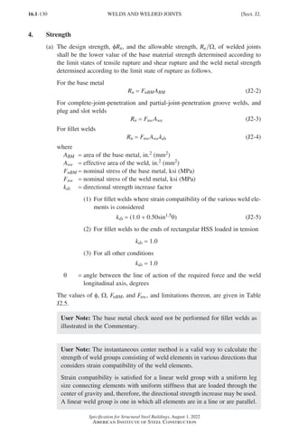
![16.1-131
Specification for Structural Steel Buildings, August 1, 2022
American Institute of Steel Construction
TABLE J2.5
Available Strength of Welded Joints, ksi (MPa)
Load Type and
Direction
Relative to
Weld Axis
Pertinent
Metal f
f and W
W
Nominal
Stress,
FnBM or
Fnw,
ksi (MPa)
Effective
Area,
ABM or
Awe,
in.2 (mm2)
Required Filler
Metal Strength
Level[a][b]
COMPLETE-JOINT-PENETRATION GROOVE WELDS
Tension—
normal to weld axis
Strength of the joint is controlled
by the base metal.
Matching filler metal
shall be used. For
T- and corner-joints
with backing left in
place, notch tough filler
metal is required.
See Section J2.6.
Compression—
normal to weld axis
Strength of the joint is controlled
by the base metal.
Filler metal with a
strength level equal to
or one strength level
less than matching filler
metal is permitted.
Tension or
compression—
parallel to weld axis
Tension or compression in parts joined
parallel to a weld is permitted to be
neglected in design of welds joining the
parts.
Filler metal with a
strength level equal to
or less than matching
filler metal is permitted.
Shear
Strength of the joint is controlled
by the base metal.
Matching filler metal
shall be used.[c]
PARTIAL-JOINT-PENETRATION GROOVE WELDS INCLUDING FLARE-V-GROOVE
AND FLARE-BEVEL-GROOVE WELDS
Tension—
normal to weld axis
Base
f
f = 0.75
W
W = 2.00
Fu See J4
Filler metal with a
strength level equal
to or less than
matching filler metal
is permitted.
Weld
f
f = 0.80
W
W = 1.88
0.60FEXX See J2.1a
Compression—
connections of
members designed to
bear as described in
Section J1.4(b)
Compressive stress is permitted
to be neglected in design of welds
joining the parts.
Compression—
connections not
designed to bear
Base
f
f = 0.90
W
W = 1.67
Fy See J4
Weld
f
f = 0.80
W
W = 1.88
0.90FEXX See J2.1a
Tension or
compression—
parallel to weld axis
Tension or compression in parts joined
parallel to a weld is permitted to be neglected
in design of welds joining the parts.
Shear
Base Governed by J4
Weld
f
f = 0.75
W
W = 2.00
0.60FEXX See J2.1a
Sect. J2.] WELDS AND WELDED JOINTS
Part 16.1 J-N (121-194).indd 131
Part 16.1 J-N (121-194).indd 131 2023-01-10 8:06 PM
2023-01-10 8:06 PM](https://image.slidesharecdn.com/aisc360-22specificationforstructuralsteelbuildings-231108145904-1b416cfe/85/AISC-360-22-Specification-for-Structural-Steel-Buildings-pdf-199-320.jpg)
![16.1-132
Specification for Structural Steel Buildings, August 1, 2022
American Institute of Steel Construction
TABLE J2.5 (continued)
Available Strength of Welded Joints, ksi (MPa)
Load Type and
Direction
Relative to
Weld Axis
Pertinent
Metal f
f and W
W
Nominal
Stress,
FnBM or
Fnw,
ksi (MPa)
Effective
Area,
ABM or
Awe,
in.2 (mm2)
Required Filler
Metal Strength
Level[a][b]
FILLET WELDS INCLUDING FILLETS IN HOLES AND SLOTS AND SKEWED T-JOINTS
Shear
Base Governed by J4
Filler metal with a
strength level equal to
or less than matching
filler metal is permitted.
Weld
f
f = 0.75
W
W = 2.00
0.60FEXX
[d] See J2.2a
Tension or
compression—
parallel to weld axis
Tension or compression in parts joined
parallel to a weld is permitted to be
neglected in design of welds joining
the parts.
PLUG AND SLOT WELDS
Shear—parallel to
faying surface on the
effective area
Base Governed by J4 Filler metal with a
strength level equal to
or less than matching
filler metal is permitted.
Weld
f
f = 0.75
W
W = 2.00
0.60FEXX See J2.3a
FEXX = filler metal classification strength, ksi (MPa)
[a]For matching weld metal, see AWS D1.1/D1.1M, clause 5.6.1.
[b]Filler metal with a strength level one strength level greater than matching is permitted.
[c]
Filler metals with a strength level less than matching are permitted to be used for CJP groove welds
between the webs and flanges of built-up sections transferring shear loads, or in applications where high
restraint is a concern. In these applications, the weld joint shall be detailed and the weld shall be designed
using the thickness of the material as the effective throat, where f = 0.80, W = 1.88, and 0.60FEXX is the
nominal strength.
[d]The provisions of Section J2.4(a) are also applicable.
(b)
For fillet weld groups concentrically loaded and consisting of elements with a
uniform leg size that are oriented both longitudinally and transversely to the
direction of applied load, the nominal strength, Rn, of the fillet weld group is
permitted to be determined as
Rn = 0.85 FnwAwel + 1.5FnwAwet (J2-6)
where
Awel = effective area of longitudinally loaded fillet welds, in.2 (mm2)
Awet = effective area of transversely loaded fillet welds, in.2 (mm2)
User Note: The nominal strength of fillet welds groups consisting of ele-
ments that are oriented both longitudinally and transversely to the direction
of applied load can also be calculated in accordance with Section J2.4(a)
neglecting the directional strength increase.
WELDS AND WELDED JOINTS [Sect. J2.
Part 16.1 J-N (121-194).indd 132
Part 16.1 J-N (121-194).indd 132 2023-01-10 8:06 PM
2023-01-10 8:06 PM](https://image.slidesharecdn.com/aisc360-22specificationforstructuralsteelbuildings-231108145904-1b416cfe/85/AISC-360-22-Specification-for-Structural-Steel-Buildings-pdf-200-320.jpg)
![16.1-133
Specification for Structural Steel Buildings, August 1, 2022
American Institute of Steel Construction
5. Combination of Welds
If two or more of the general types of welds (groove, fillet, plug, slot) are combined
in a single joint, the strength of each shall be separately computed with reference to
the axis of the group in order to determine the strength of the combination.
6. Filler Metal Requirements
The choice of filler metal for use with CJP groove welds subjected to tension normal
to the effective area shall comply with the requirements for matching filler metals
given in AWS D1.1/D1.1M.
User Note: The following User Note Table summarizes the AWS D1.1/D1.1M
provisions for matching filler metals. Other restrictions exist. For a com-
plete list of base metals and prequalified matching filler metals, see AWS
D1.1/D1.1M, Table 5.3 and Table 5.4.
Base Metal (ASTM) Matching Filler Metal
A36/A36M ≤ 3
/4 in. (19 mm) thick 60 and 70 ksi filler metal
A36/A36M 3
/4 in. (19 mm) thick, A588/
A588M[a], A1011/A1011M, A572/A572M
Grade 50 (345) and 55 (380), A913/
A913M Grade 50 (345), A992/A992M
SMAW: E7015, E7016, E7018, E7028
Other processes: 70 ksi filler metal
A913/A913M Grade 60 (415) and 65
(450)
80 ksi (550 MPa) filler metal
A913/A913M Grade 70 (485) 90 ksi (620 MPa) filler metal
[a]
For corrosion resistance and color similar to the base metal, see AWS D1.1/D1.1M, clause
5.6.2.
Note:
In joints with base metals of different strengths, either a filler metal that matches the higher
strength base metal or a filler metal that matches the lower strength and produces a low hydro-
gen deposit may be used when matching strength is required.
Filler metal with a specified minimum Charpy V-notch toughness of 20 ft-lb (27 J)
at 40°F (4°C) or lower shall be used in the following joints:
(a)
CJP groove welded T- and corner-joints with steel backing left in place, sub-
jected to tension normal to the effective area, unless the joints are designed using
the nominal strength and resistance factor or safety factor, as applicable, for a
PJP groove weld
(b)
CJP groove welded splices subjected to tension normal to the effective area in
heavy shapes, as defined in Sections A3.1d and A3.1e
The manufacturer’s Certificate of Conformance shall be sufficient evidence of com-
pliance.
7. Mixed Weld Metal
When Charpy V-notch toughness is specified, the process consumables for all weld
metal, tack welds, root pass, and subsequent passes deposited in a joint shall be
compatible to ensure notch-tough composite weld metal.
Sect. J2.] WELDS AND WELDED JOINTS
Part 16.1 J-N (121-194).indd 133
Part 16.1 J-N (121-194).indd 133 2023-01-29 11:58 AM
2023-01-29 11:58 AM](https://image.slidesharecdn.com/aisc360-22specificationforstructuralsteelbuildings-231108145904-1b416cfe/85/AISC-360-22-Specification-for-Structural-Steel-Buildings-pdf-201-320.jpg)
![16.1-135
Specification for Structural Steel Buildings, August 1, 2022
American Institute of Steel Construction
(b) Bolts in the following connections shall be pretensioned:
(1) As required by the RCSC Specification
(2)
Connections subjected to vibratory loads where bolt loosening is a consid-
eration
(3)
End connections of built-up members composed of two shapes either
interconnected by bolts, or with at least one open side interconnected by
perforated cover plates or lacing with tie plates, as required in Section E6.1
(c) The following connections shall be designed as slip-critical:
(1) As required by the RCSC Specification
(2)
The extended portion of bolted, partial-length cover plates, as required in
Section F13.3
The snug-tight condition is defined in the RCSC Specification. Bolts to be tight-
ened to a condition other than snug tight shall be clearly identified on the design
documents. (See Table J3.1 or J3.1M for minimum bolt pretension for connections
designated as pretensioned or slip-critical.)
User Note: There are no specific minimum or maximum tension requirements
for snug-tight bolts. Bolts that have been pretensioned are permitted in snug-tight
connections unless specifically prohibited on design documents.
When bolt requirements cannot be provided within the RCSC Specification limi-
tations because of requirements for lengths exceeding 12 diameters or diameters
exceeding 12 in. (38 mm), bolts or threaded rods conforming to Group 120 or Group
150 materials are permitted to be used in accordance with the provisions for threaded
parts in Table J3.2.
When ASTM A354 Grade BC, ASTM A354 Grade BD, or ASTM A449 bolts and
threaded rods are used in pretensioned connections, the bolt geometry, including
the thread pitch, thread length, head, and nut(s), shall be equal to or (if larger in
diameter) proportional to that required by the RCSC Specification. Installation shall
comply with all applicable requirements of the RCSC Specification with modifica-
tions as required for the increased diameter and/or length to provide the design
pretension.
3. Size and Use of Holes
The following requirements apply for bolted connections:
(a)
The nominal dimensions of standard, oversized, short-slotted, and long-slotted
holes for bolts are given in Table J3.3 or Table J3.3M.
User Note: Bolt holes with a smaller nominal diameter are permitted. See
RCSC Specification Table 3.1 for bolt hole fabrication tolerances. See
Section J9 for diameters of holes in base plates for anchor rods providing
anchorage to concrete.
Sect. J3.] BOLTS, THREADED PARTS, AND BOLTED CONNECTIONS
Part 16.1 J-N (121-194).indd 135
Part 16.1 J-N (121-194).indd 135 2023-01-10 8:06 PM
2023-01-10 8:06 PM](https://image.slidesharecdn.com/aisc360-22specificationforstructuralsteelbuildings-231108145904-1b416cfe/85/AISC-360-22-Specification-for-Structural-Steel-Buildings-pdf-203-320.jpg)
![16.1-136
Specification for Structural Steel Buildings, August 1, 2022
American Institute of Steel Construction
TABLE J3.1
Minimum Bolt Pretension, kips
Bolt Size, in. Group 120[a]
Group 144[b] and
Group 150[b]
Group 200,
Grade 2[c]
1
/2
5
/8
3
/4
7
/8
1
11
/8
11
/4
13
/8
11
/2
12
19
28
39
51
64
81
97
118
15
24
35
49
64
80
102
121
148
−
−
−
−
90
113
143
−
−
[a]
Equal to 0.70 times the minimum tensile strength of bolts as specified in ASTM F3125/F3125M for Grade
A325 rounded off to nearest kip.
[b]
Equal to 0.70 times the minimum tensile strength of bolts as specified in ASTM F3125/F3125M for Grade
A490 rounded off to nearest kip. Group 144 (F3148) assemblies have the same specified minimum preten-
sion as Group 150.
[c]
Equal to 0.70 times the minimum tensile strength of bolts as specified in ASTM F3043 and F3111 for Grade
2, rounded off to the nearest kip.
TABLE J3.1M
Minimum Bolt Pretension, kN
Bolt Size, mm Group 120[a] Group 150[b]
M12
M16
M20
M22
M24
M27
M30
M36
49
91
142
176
205
267
326
475
72
114
179
221
257
334
408
595
[a]
Equal to 0.70 times the minimum tensile strength of bolts as specified in ASTM F3125/F3125M for Grade
A325M bolts, rounded off to nearest kN.
[b]
Equal to 0.70 times the minimum tensile strength of bolts as specified in ASTM F3125/F3125M for Grade
A490M bolts, rounded off to nearest kN.
(b)
Standard holes or short-slotted holes transverse to the direction of the load
shall be provided in accordance with the provisions of this Specification, unless
oversized holes, short-slotted holes parallel to the load, or long-slotted holes are
approved by the engineer of record.
(c)
Finger shims up to 4 in. (6 mm) are permitted in slip-critical connections de-
signed on the basis of standard holes without reducing the nominal shear strength
of the fastener to that specified for slotted holes.
User Note: Metric grades manufactured to ASTM F3125/F3125M Grade A325M
and A490M are similar to Group 120 (830 MPa) and Group 150 (1 040 MPa),
respectively.
BOLTS, THREADED PARTS, AND BOLTED CONNECTIONS [Sect. J3.
Part 16.1 J-N (121-194).indd 136
Part 16.1 J-N (121-194).indd 136 2023-01-10 8:06 PM
2023-01-10 8:06 PM](https://image.slidesharecdn.com/aisc360-22specificationforstructuralsteelbuildings-231108145904-1b416cfe/85/AISC-360-22-Specification-for-Structural-Steel-Buildings-pdf-204-320.jpg)
![16.1-137
Specification for Structural Steel Buildings, August 1, 2022
American Institute of Steel Construction
TABLE J3.2
Nominal Stress of Fasteners and Threaded Parts,
ksi (MPa)
Description of Fasteners
Nominal
Tensile
Stress,
Fnt, ksi
(MPa)[a][b]
Nominal Shear Stress in
Bearing-Type Connections,
Fnv, ksi (MPa)[c]
Threads Not
Excluded from
Shear Planes—
(N)[e]
Threads Excluded
from Shear Planes
—(X)
A307 bolts 45 (310) 27 (190)[d] 27 (190)[d]
Group 120 (e.g., A325) 90 (620) 54 (370) 68 (470)
Group 144 (e.g., F3148) 108 (750) 65 (450) 81 (560)
Group 150 (e.g., A490) 113 (780) 68 (470) 84 (580)
Group 200 (e.g., F3043) 150 (1000) 90 (620)[f] 113 (780)[f]
Threaded parts meeting
the requirements of
Section A3.4
0.75Fu 0.450Fu 0.563Fu
[a]For high-strength bolts subjected to tensile fatigue loading, see Appendix 3.
[b]
For nominal tensile strength it is permitted to use the tensile stress area of the threaded rod or bolt multi-
plied by the specified minimum tensile stress of the rod or bolt material, in lieu of the tabulated values based
on a nominal tensile stress area of 0.75 times the gross area. The tensile stress area shall be calculated in
accordance with the applicable ASTM standard.
[c]
For end-loaded connections with a fastener pattern length greater than 38 in. (950 mm), Fnv shall be reduced
to 83.3% of the tabulated values. Fastener pattern length is the maximum distance parallel to the line of
force between the centerline of the bolts connecting two parts with one faying surface.
[d]
For ASTM A307 bolts, the tabulated values shall be reduced by 1% for each 1
/16 in. (2 mm) over five diam-
eters of length in the grip.
[e]Threads assumed and permitted in shear planes in all cases.
[f] The transition area of Group 200 bolts is considered part of the threaded section.
TABLE J3.3
Nominal Hole Dimensions, in.
Bolt
Diameter
Hole Dimensions
Standard
(Dia.)
Oversize
(Dia.)
Short-Slot
(Width ×
× Length)
Long-Slot
(Width ×
× Length)
1
/2
5
/8
3
/4
7
/8
1
≥11
/8
9
/16
11
/16
13
/16
15
/16
11
/8
d + 1
/8
5
/8
13
/16
15
/16
11
/16
11
/4
d + 5
/16
9
/16 × 11
/16
11
/16 × 7
/8
13
/16 × 1
15
/16 × 11
/8
11
/8 × 15
/16
(d + 1
/8) × (d + 3
/8)
9
/16 × 11
/4
11
/16 × 19
/16
13
/16 × 17
/8
15
/16 × 23
/16
11
/8 × 21
/2
(d + 1
/8) × 2.5d
Sect. J3.] BOLTS, THREADED PARTS, AND BOLTED CONNECTIONS
Part 16.1 J-N (121-194).indd 137
Part 16.1 J-N (121-194).indd 137 2023-01-10 8:06 PM
2023-01-10 8:06 PM](https://image.slidesharecdn.com/aisc360-22specificationforstructuralsteelbuildings-231108145904-1b416cfe/85/AISC-360-22-Specification-for-Structural-Steel-Buildings-pdf-205-320.jpg)
![16.1-138
Specification for Structural Steel Buildings, August 1, 2022
American Institute of Steel Construction
TABLE J3.3M
Nominal Hole Dimensions, mm
Bolt
Diameter
Hole Dimensions
Standard
(Dia.)
Oversize
(Dia.)
Short-Slot
(Width ×
×
Length)
Long-Slot
(Width ×
×
Length)
M12
M16
M20
M22
M24
M27
M30
≥M36
14
18
22
24
27[a]
30
33
d + 3
16
20
24
28
30
35
38
d + 8
14 × 18
18 × 22
22 × 26
24 × 30
27 × 32
30 × 37
33 × 40
(d + 3) × (d + 10)
14 × 30
18 × 40
22 × 50
24 × 55
27 × 60
30 × 67
33 × 75
(d + 3) × 2.5d
[a]Clearance provided allows the use of a 1-in.-diameter bolt.
(d) Oversized holes are permitted in any or all plies of slip-critical connections, but
they shall not be used in bearing-type connections.
(e)
Short-slotted holes are permitted in any or all plies of slip-critical or bearing-
type connections. The slots are permitted without regard to direction of loading
in slip-critical connections, but the length shall be normal to the direction of the
loading in bearing-type connections.
(f) Long-slotted holes are permitted in only one of the connected parts of either a
slip-critical or bearing-type connection at an individual faying surface. Long-
slotted holes are permitted without regard to direction of loading in slip-critical
connections, but shall be normal to the direction of loading in bearing-type con-
nections.
(g)
Washers shall be provided in accordance with the RCSC Specification Section
6, except for Group 200 bolting assemblies where washers shall be provided in
accordance with the applicable ASTM standard.
User Note: When Group 200 heavy-hex bolting assemblies are used, a single
washer is used under the bolt head and a single washer is used under the nut.
When Group 200 twist-off bolting assemblies are used, a single washer is used
under the nut. Washers are of the type specified in the ASTM standard for the
bolting assembly.
4. Minimum Spacing
The distance between centers of standard, oversized, or slotted holes shall not be less
than 2q times the nominal diameter, d, of the fastener. However, the clear distance
between bolt holes or slots shall not be less than d.
User Note: A distance between centers of standard, oversized, or slotted holes
of 3d is preferred.
BOLTS, THREADED PARTS, AND BOLTED CONNECTIONS [Sect. J3.
Part 16.1 J-N (121-194).indd 138
Part 16.1 J-N (121-194).indd 138 2023-01-10 8:06 PM
2023-01-10 8:06 PM](https://image.slidesharecdn.com/aisc360-22specificationforstructuralsteelbuildings-231108145904-1b416cfe/85/AISC-360-22-Specification-for-Structural-Steel-Buildings-pdf-206-320.jpg)
![16.1-139
Specification for Structural Steel Buildings, August 1, 2022
American Institute of Steel Construction
TABLE J3.4
Minimum Edge Distance[a] from
Center of Standard Hole[b] to Edge of
Connected Part, in.
Bolt Diameter Minimum Edge Distance
1
/2
5
/8
3
/4
7
/8
1
11
/8
11
/4
Over 11
/4
3
/4
7
/8
1
11
/8
11
/4
11
/2
15
/8
11
/4d
[a]
If necessary, lesser edge distances are permitted provided the applicable provisions from Sections J3.11
and J4 are satisfied, but edge distances less than one bolt diameter are not permitted without approval
from the engineer of record.
[b]For oversized or slotted holes, see Table J3.5.
TABLE J3.4M
Minimum Edge Distance[a] from
Center of Standard Hole[b] to Edge of
Connected Part, mm
Bolt Diameter Minimum Edge Distance
12
16
20
22
24
27
30
36
Over 36
18
22
26
28
30
34
38
46
1.25d
[a]
If necessary, lesser edge distances are permitted provided the applicable provisions from Sections J3.11
and J4 are satisfied, but edge distances less than one bolt diameter are not permitted without approval
from the engineer of record.
[b]For oversized or slotted holes, see Table J3.5M.
5. Minimum Edge Distance
The distance from the center of a standard hole to an edge of a connected part in
any direction shall not be less than either the applicable value from Table J3.4 or Table
J3.4M, or as required in Section J3.11. The distance from the center of an oversized
or slotted hole to an edge of a connected part shall be not less than that required for a
standard hole to an edge of a connected part plus the applicable increment, C2, from
Table J3.5 or Table J3.5M.
Sect. J3.] BOLTS, THREADED PARTS, AND BOLTED CONNECTIONS
Part 16.1 J-N (121-194).indd 139
Part 16.1 J-N (121-194).indd 139 2023-01-10 8:06 PM
2023-01-10 8:06 PM](https://image.slidesharecdn.com/aisc360-22specificationforstructuralsteelbuildings-231108145904-1b416cfe/85/AISC-360-22-Specification-for-Structural-Steel-Buildings-pdf-207-320.jpg)
![16.1-140
Specification for Structural Steel Buildings, August 1, 2022
American Institute of Steel Construction
TABLE J3.5
Values of Edge Distance Increment C2, in.
Nominal
Diameter of
Fastener
Oversized
Holes
Slotted Holes
Long Axis Perpendicular to Edge
Long Axis
Parallel to Edge
Short Slots Long Slots[a]
≤ 7
/8
1
/16
1
/8
3
/4d 0
1 1
/8
1
/8
≥ 11
/8
1
/8
3
/16
[a]
When the length of the slot is less than the maximum allowable (see Table J3.3), C2 is permitted to be
reduced by one-half the difference between the maximum and actual slot lengths.
TABLE J3.5M
Values of Edge Distance Increment C2, mm
Nominal
Diameter of
Fastener
Oversized
Holes
Slotted Holes
Long Axis Perpendicular to Edge
Long Axis
Parallel to Edge
Short Slots Long Slots[a]
≤ 22 2 3
0.75d 0
24 3 3
≥ 27 3 5
[a]
When the length of the slot is less than the maximum allowable (see Table J3.3M), C2 is permitted to be
reduced by one-half the difference between the maximum and actual slot lengths.
User Note: The edge distances in Tables J3.4 and J3.4M are minimum edge dis-
tances based on standard fabrication practices and workmanship tolerances. The
appropriate provisions of Sections J3.11 and J4 must be satisfied.
6. Maximum Spacing and Edge Distance
The maximum distance from the center of any bolt hole to the nearest edge of ele-
ments in contact shall be 12 times the thickness of the connected element under
consideration, but shall not exceed 6 in. (150 mm). The longitudinal spacing of bolt
holes between elements consisting of a plate and a shape, or two plates, in continuous
contact shall be as follows:
(a)
For painted members or unpainted members not subject to atmospheric corrosion,
the spacing shall not exceed 24 times the thickness of the thinner part or 12 in.
(300 mm).
(b)
For unpainted members of weathering steel subject to atmospheric corrosion,
the spacing shall not exceed 14 times the thickness of the thinner part or 7 in.
(180 mm).
BOLTS, THREADED PARTS, AND BOLTED CONNECTIONS [Sect. J3.
Part 16.1 J-N (121-194).indd 140
Part 16.1 J-N (121-194).indd 140 2023-01-10 8:06 PM
2023-01-10 8:06 PM](https://image.slidesharecdn.com/aisc360-22specificationforstructuralsteelbuildings-231108145904-1b416cfe/85/AISC-360-22-Specification-for-Structural-Steel-Buildings-pdf-208-320.jpg)
![16.1-141
Specification for Structural Steel Buildings, August 1, 2022
American Institute of Steel Construction
User Note: The dimensions in (a) and (b) do not apply to elements consisting of
two shapes in continuous contact.
7. Tensile and Shear Strength of Bolts and Threaded Parts
The design tensile or shear strength, φRn, and the allowable tensile or shear strength,
Rn Ω, of a snug-tightened or pretensioned high-strength bolt or threaded part shall
be determined according to the limit states of tension rupture and shear rupture as
Rn = FnAb (J3-1)
φ = 0.75 (LRFD) Ω = 2.00 (ASD)
where
Ab = nominal unthreaded body area of bolt or threaded part, in.2 (mm2)
Fn = nominal tensile stress, Fnt, or shear stress, Fnv, from Table J3.2, ksi (MPa)
The required tensile strength shall include any tension resulting from prying action
produced by deformation of the connected parts.
User Note: The available strength of a bolt in shear depends on whether the bolt
is sheared through its shank or through the threads or thread runout. Bolts that are
relatively short may be produced as fully threaded, without a shank, and thus may
not be able to be installed in the “threads excluded” condition.
User Note: The force that can be resisted by a snug-tightened or pretensioned
high-strength bolt or threaded part may be limited by the bearing or tearout
strength at the bolt hole per Section J3.11. The effective strength of an individual
fastener may be taken as the lesser of the fastener shear strength per Section J3.7 or
the bearing or tearout strength at the bolt hole per Section J3.11. The strength of the
bolt group is taken as the sum of the effective strengths of the individual fasteners.
8. Combined Tension and Shear in Bearing-Type Connections
The available tensile strength of a bolt subjected to combined tension and shear shall
be determined according to the limit states of tension and shear rupture as
R F A
n nt b
= ′ (J3-2)
φ = 0.75 (LRFD) Ω = 2.00 (ASD)
where
′
Fnt =
nominal tensile stress modified to include the effects of shear stress, ksi (MPa)
=
1 3
. F
F
F
f F
nt
nt
nv
rv nt
− ≤
φ
(LRFD) (J3-3a)
=
1 3
. F
F
F
f F
nt
nt
nv
rv nt
− ≤
Ω
(ASD) (J3-3b)
Fnt = nominal tensile stress from Table J3.2, ksi (MPa)
Fnv = nominal shear stress from Table J3.2, ksi (MPa)
frv = required shear stress using LRFD or ASD load combinations, ksi (MPa)
Sect. J3.] BOLTS, THREADED PARTS, AND BOLTED CONNECTIONS
Part 16.1 J-N (121-194).indd 141
Part 16.1 J-N (121-194).indd 141 2023-01-10 8:06 PM
2023-01-10 8:06 PM](https://image.slidesharecdn.com/aisc360-22specificationforstructuralsteelbuildings-231108145904-1b416cfe/85/AISC-360-22-Specification-for-Structural-Steel-Buildings-pdf-209-320.jpg)
![16.1-143
Specification for Structural Steel Buildings, August 1, 2022
American Institute of Steel Construction
(2)
For Class B surfaces (unpainted blast-cleaned steel surfaces or surfaces
with Class B coatings on blast-cleaned steel)
µ = 0.50
10. Combined Tension and Shear in Slip-Critical Connections
When a slip-critical connection is subjected to an applied tension that reduces the
net clamping force, the available slip resistance per bolt from Section J3.9 shall be
multiplied by the factor, ksc, determined as follows:
k
T
D T n
sc
u
u b b
= − ≥
1 0 (LRFD) (J3-5a)
k
T
D T n
sc
a
u b b
.
= − ≥
1
1 5
0 (ASD) (J3-5b)
where
Ta = required tension force using ASD load combinations, kips (kN)
Tu = required tension force using LRFD load combinations, kips (kN)
nb = number of bolts carrying the applied tension
11. Bearing and Tearout Strength at Bolt Holes
The available strength, φRn and Rn Ω, at bolt holes shall be determined for the limit
states of bearing and tearout, as follows:
φ = 0.75 (LRFD) Ω = 2.00 (ASD)
The nominal strength of the connected material, Rn, shall be determined in accor-
dance with Section J3.11a or Section J3.11b.
11a. Snug-Tightened or Pretensioned High-Strength Bolted Connections
All plies of the connected elements shall be in firm contact.
(1)
The nominal strength of a connected element at a bolt in a connection with stan-
dard, oversized, and short-slotted holes, independent of the direction of loading,
or a long-slotted hole with the slot parallel to the direction of the bearing force,
shall be the lesser of the following:
(a) Bearing
(i)
When deformation at the bolt hole at service load is a design considera-
tion
Rn = 2.4dtFu (J3-6a)
(ii)
When deformation at the bolt hole at service load is not a design con-
sideration
Rn = 3.0dtFu (J3-6b)
Sect. J3.] BOLTS, THREADED PARTS, AND BOLTED CONNECTIONS
Part 16.1 J-N (121-194).indd 143
Part 16.1 J-N (121-194).indd 143 2023-01-10 8:06 PM
2023-01-10 8:06 PM](https://image.slidesharecdn.com/aisc360-22specificationforstructuralsteelbuildings-231108145904-1b416cfe/85/AISC-360-22-Specification-for-Structural-Steel-Buildings-pdf-211-320.jpg)
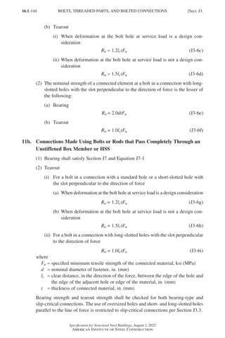
![16.1-145
Specification for Structural Steel Buildings, August 1, 2022
American Institute of Steel Construction
12. Special Fasteners
The nominal strength of special fasteners other than the bolts presented in Table J3.2
shall be verified by tests.
13. Wall Strength at Tension Fasteners
When bolts or other fasteners in tension are attached to an unstiffened box or HSS
wall, the strength of the wall shall be determined by rational analysis.
J4.
AFFECTED ELEMENTS OF MEMBERS AND CONNECTING
ELEMENTS
This section applies to elements of members at connections and connecting elements,
such as plates, gussets, angles, and brackets.
1. Strength of Elements in Tension
The design strength, φRn, and the allowable strength, Rn Ω, of affected and connect-
ing elements loaded in tension shall be the lower value obtained according to the
limit states of tensile yielding and tensile rupture.
(a) For tensile yielding of connecting elements
Rn = FyAg (J4-1)
φ = 0.90 (LRFD) Ω = 1.67 (ASD)
(b) For tensile rupture of connecting elements
Rn = FuAe (J4-2)
φ = 0.75 (LRFD) Ω = 2.00 (ASD)
where
Ae = effective net area as defined in Section D3, in.2 (mm2)
User Note: The effects of shear lag or concentrated loads dispersed within the
element may cause only a portion of the area to be effective in resisting the load.
For shear lag, see Chapter D.
2. Strength of Elements in Shear
The available shear strength of affected and connecting elements in shear shall be
the lower value obtained according to the limit states of shear yielding and shear
rupture:
(a) For shear yielding of the element
Rn = 0.60FyAgv (J4-3)
φ = 1.00 (LRFD) Ω = 1.50 (ASD)
where
Agv = gross area subjected to shear, in.2 (mm2)
Sect. J4.] AFFECTED ELEMENTS OF MEMBERS AND CONNECTING ELEMENTS
Part 16.1 J-N (121-194).indd 145
Part 16.1 J-N (121-194).indd 145 2023-01-10 8:06 PM
2023-01-10 8:06 PM](https://image.slidesharecdn.com/aisc360-22specificationforstructuralsteelbuildings-231108145904-1b416cfe/85/AISC-360-22-Specification-for-Structural-Steel-Buildings-pdf-213-320.jpg)
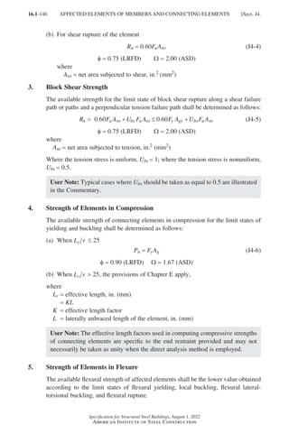
![16.1-147
Specification for Structural Steel Buildings, August 1, 2022
American Institute of Steel Construction
J5. FILLERS
1. Fillers in Welded Connections
Whenever it is necessary to use fillers in joints required to transfer applied force, the
fillers and the connecting welds shall conform to the requirements of Section J5.1a
or Section J5.1b, as applicable.
1a. Thin Fillers
Fillers less than 4 in. (6 mm) thick shall not be used to transfer stress. When the
thickness of the fillers is less than 4 in. (6 mm), or when the thickness of the filler
is 4 in. (6 mm) or greater but not sufficient to transfer the applied force between the
connected parts, the filler shall be kept flush with the edge of the outside connected
part, and the size of the weld shall be increased over the required size by an amount
equal to the thickness of the filler.
1b. Thick Fillers
When the thickness of the fillers is sufficient to transfer the applied force between
the connected parts, the filler shall extend beyond the edges of the outside connected
base metal. The welds joining the outside connected base metal to the filler shall be
sufficient to transmit the force to the filler and the region subjected to the applied
force in the filler shall be sufficient to prevent overstressing the filler. The welds
joining the filler to the inside connected base metal shall be sufficient to transmit the
applied force.
2. Fillers in Bolted Bearing-Type Connections
When a bolt that carries load passes through fillers that are equal to or less than
4 in. (6 mm) thick, the shear strength shall be used without reduction. When a bolt
that carries load passes through fillers that are greater than 4 in. (6 mm) thick, one
of the following requirements shall apply:
(a) The shear strength of the bolts shall be multiplied by the factor
1 − 0.4(t − 0.25)
1 − 0.0154(t − 6) (S.I.)
but not less than 0.85, where t is the total thickness of the fillers.
(b)
The fillers shall be welded or extended beyond the joint and bolted to uniformly
distribute the total force in the connected element over the combined cross sec-
tion of the connected element and the fillers.
(c)
The size of the joint shall be increased to accommodate a number of bolts that is
equivalent to the total number required in (b).
J6. SPLICES
Groove-welded splices in beams shall develop the nominal strength of the smaller
spliced section. Other types of splices in cross sections of beams shall develop the
strength required by the forces at the point of the splice.
Sect. J6.] SPLICES
Part 16.1 J-N (121-194).indd 147
Part 16.1 J-N (121-194).indd 147 2023-01-10 8:06 PM
2023-01-10 8:06 PM](https://image.slidesharecdn.com/aisc360-22specificationforstructuralsteelbuildings-231108145904-1b416cfe/85/AISC-360-22-Specification-for-Structural-Steel-Buildings-pdf-215-320.jpg)
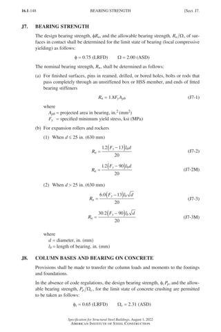
![16.1-149
Specification for Structural Steel Buildings, August 1, 2022
American Institute of Steel Construction
The nominal bearing strength, Pp, is determined as follows:
(a) On the full area of a concrete support
P f A
p c
= ′
0.85 1 (J8-1)
(b) On less than the full area of a concrete support
P f A A A f A
p c c
= ′ ≤ ′
0 85 1 2 1
. .
17 1 (J8-2)
where
A1 = area of steel concentrically bearing on a concrete support, in.2 (mm2)
A2 =
maximum area of the portion of the supporting surface that is geometrically
similar to and concentric with the loaded area, in.2 (mm2)
′
fc = specified compressive strength of concrete, ksi (MPa)
J9. ANCHOR RODS AND EMBEDMENTS
Anchor rods shall be designed to provide the required resistance to loads on the
completed structure at the base of columns including the net tensile components
of any bending moment resulting from load combinations stipulated in Section B2.
The anchor rods shall be designed in accordance with the requirements for threaded
parts in Table J3.2.
Design of anchor rods for the transfer of forces to the concrete foundation shall sat-
isfy the requirements of ACI 318 (ACI 318M) or ACI 349 (ACI 349M).
User Note: Column bases should be designed considering bearing against con-
crete elements, including when columns are required to resist a horizontal force
at the base plate. See AISC Design Guide 1, Base Plate and Anchor Rod Design,
Second Edition, for column base design information.
When anchor rods are used to resist horizontal forces, hole size, anchor rod setting
tolerance, and the horizontal movement of the column shall be considered in the
design.
Holes and slots larger than oversized holes and slots in Table J3.3 or Table J3.3M
are permitted in base plates when adequate bearing is provided for the nut by using
ASTM F844 washers or plate washers to bridge the hole.
User Note: The recommended hole sizes and corresponding washer dimensions
and nuts are given in the AISC Steel Construction Manual and ASTM F1554.
ASTM F1554 anchor rods may be furnished in accordance with product specifica-
tions with a body diameter less than the nominal diameter. Load effects such as
bending and elongation should be calculated based on minimum diameters per-
mitted by the product specification. See ASTM F1554 and the table, “Applicable
ASTM Specifications for Various Types of Structural Fasteners,” in the AISC
Steel Construction Manual Part 2.
Sect. J9.] ANCHOR RODS AND EMBEDMENTS
Part 16.1 J-N (121-194).indd 149
Part 16.1 J-N (121-194).indd 149 2023-01-29 12:10 PM
2023-01-29 12:10 PM](https://image.slidesharecdn.com/aisc360-22specificationforstructuralsteelbuildings-231108145904-1b416cfe/85/AISC-360-22-Specification-for-Structural-Steel-Buildings-pdf-217-320.jpg)
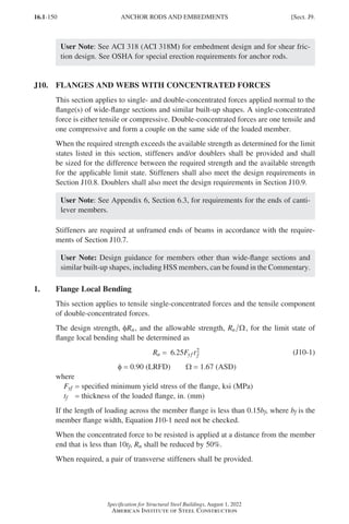
![16.1-151
Specification for Structural Steel Buildings, August 1, 2022
American Institute of Steel Construction
2. Web Local Yielding
This section applies to single-concentrated forces and both components of double-
concentrated forces.
The available strength for the limit state of web local yielding shall be determined
as follows:
φ = 1.00 (LRFD) Ω = 1.50 (ASD)
The nominal strength, Rn, shall be determined as follows:
(a)
When the concentrated force to be resisted is applied at a distance from the
member end that is greater than the full nominal depth of the member, d
R F t k l
n yw w b
= +
( )
5 (J10-2)
(b)
When the concentrated force to be resisted is applied at a distance from the
member end that is less than or equal to the full nominal depth of the member, d
R F t k l
n yw w b
= +
( )
2 5
. (J10-3)
where
Fyw = specified minimum yield stress of the web material, ksi (MPa)
k = distance from outer face of the flange to the web toe of the fillet, in. (mm)
lb = length of bearing, in. (mm)
tw = thickness of web, in. (mm)
When required, a pair of transverse stiffeners or a doubler plate shall be provided.
3. Web Local Crippling
This section applies to compressive single-concentrated forces or the compressive
component of double-concentrated forces.
The available strength for the limit state of web local crippling shall be determined
as follows:
φ = 0.75 (LRFD) Ω = 2.00 (ASD)
The nominal strength, Rn, shall be determined as follows:
(a)
When the concentrated compressive force to be resisted is applied at a distance
from the member end that is greater than or equal to d 2
R t
l
d
t
t
EF t
t
Q
n w
b w
f
yw f
w
f
= +
0.80 2
1 5
1 3
.
(J10-4)
(b)
When the concentrated compressive force to be resisted is applied at a distance
from the member end that is less than d 2
(1) For l d
b ≤ 0 2
.
R t
l
d
t
t
EF t
t
Q
n w
b w
f
yw f
w
f
= +
0.40 2
1 5
1 3
.
(J10-5a)
Sect. J10.] FLANGES AND WEBS WITH CONCENTRATED FORCES
Part 16.1 J-N (121-194).indd 151
Part 16.1 J-N (121-194).indd 151 2023-01-10 8:06 PM
2023-01-10 8:06 PM](https://image.slidesharecdn.com/aisc360-22specificationforstructuralsteelbuildings-231108145904-1b416cfe/85/AISC-360-22-Specification-for-Structural-Steel-Buildings-pdf-219-320.jpg)
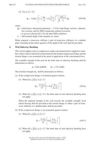
![16.1-153
Specification for Structural Steel Buildings, August 1, 2022
American Institute of Steel Construction
When the required strength of the web exceeds the available strength, local
lateral bracing shall be provided at both flanges at the point of application of the
concentrated forces.
In Equations J10-6 and J10-7, the following definitions apply:
Cr = 960,000 ksi (6.6×10⁶ MPa), when αsMr My at the location of the force
= 480,000 ksi (3.3×10⁶ MPa), when αsMr ≥ My at the location of the force
Lb =
largest laterally unbraced length along either flange at the point of load,
in. (mm)
Mr =
required flexural strength using LRFD or ASD load combinations, kip-in.
(N-mm)
My = yield moment about the axis of bending, ksi (MPa)
= FySx
bf = width of flange, in. (mm)
h =
clear distance between flanges less the fillet or corner radius for rolled shapes;
distance between adjacent lines of fasteners or the clear distance between
flanges when welds are used for built-up shapes, in. (mm)
αs = 1.0 (LRFD); 1.5 (ASD)
User Note: For determination of adequate restraint, refer to Appendix 6.
5. Web Compression Buckling
This section applies to a pair of compressive single-concentrated forces or the com-
pressive components in a pair of double-concentrated forces, applied at both flanges
of a member at the same location.
The available strength for the limit state of web compression buckling shall be deter-
mined as follows:
R
t EF
h
Q
n
w yw
f
=
24 3
(J10-8)
φ = 0.90 (LRFD) Ω = 1.67 (ASD)
where
Qf =
1.0 for wide-flange sections, channels, box sections, and for HSS (connecting
surface) in tension
=
as given in Section K1.3 for all other HSS conditions
When the pair of concentrated compressive forces to be resisted is applied at a dis-
tance from the member end that is less than d 2, Rn shall be reduced by 50%.
When required, a single transverse stiffener, a pair of transverse stiffeners, or a
doubler plate extending the full depth of the web shall be provided.
6. Web Panel-Zone Shear
This section applies to double-concentrated forces applied to one or both flanges of
a member at the same location.
Sect. J10.] FLANGES AND WEBS WITH CONCENTRATED FORCES
Part 16.1 J-N (121-194).indd 153
Part 16.1 J-N (121-194).indd 153 2023-01-29 12:02 PM
2023-01-29 12:02 PM](https://image.slidesharecdn.com/aisc360-22specificationforstructuralsteelbuildings-231108145904-1b416cfe/85/AISC-360-22-Specification-for-Structural-Steel-Buildings-pdf-221-320.jpg)
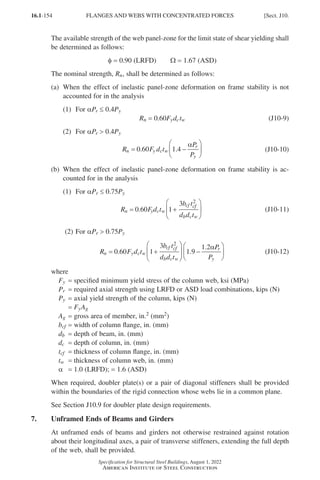
![16.1-155
Specification for Structural Steel Buildings, August 1, 2022
American Institute of Steel Construction
8. Additional Stiffener Requirements for Concentrated Forces
Stiffeners required to resist tensile concentrated forces shall be designed in accor-
dance with the requirements of Section J4.1 and welded to the loaded flange and the
web. The welds to the flange shall be sized for the difference between the required
strength and available strength. The stiffener to web welds shall be sized to transfer
to the web the algebraic difference in tensile force at the ends of the stiffener.
Stiffeners required to resist compressive concentrated forces shall be designed in
accordance with the requirements in Section J4.4 and shall either bear on or be
welded to the loaded flange and welded to the web. The welds to the flange shall be
sized for the difference between the required strength and the applicable limit state
strength. The weld to the web shall be sized to transfer to the web the algebraic dif-
ference in compression force at the ends of the stiffener. For fitted bearing stiffeners,
see Section J7.
Transverse full depth bearing stiffeners for compressive forces applied to a beam
flange(s) shall be designed as axially compressed members (columns) in accordance
with the requirements of Section E6.2 and Section J4.4. The member properties shall
be determined using an effective length of 0.75h and a cross section composed of
two stiffeners and a strip of the web having a width of 25tw at interior stiffeners and
12tw at the ends of members. The weld connecting full depth bearing stiffeners to
the web shall be sized to transmit the difference in compressive force at each of the
stiffeners to the web.
Transverse and diagonal stiffeners shall comply with the following additional re-
quirements:
(a)
The width of each stiffener plus one-half the thickness of the column web shall
not be less than one-third of the flange or moment connection plate width deliv-
ering the concentrated force.
(b)
The thickness of a stiffener shall not be less than one-half the thickness of the
flange or moment connection plate delivering the concentrated load nor less than
the width divided by 16.
(c)
Transverse stiffeners shall extend a minimum of one-half the depth of the mem-
ber except as required in Sections J10.3, J10.5, and J10.7.
9. Additional Doubler Plate Requirements for Concentrated Forces
Doubler plates required for compression strength shall be designed in accordance
with the requirements of Chapter E.
Doubler plates required for tensile strength shall be designed in accordance with the
requirements of Chapter D.
Doubler plates required for shear strength (see Section J10.6) shall be designed in
accordance with the provisions of Chapter G.
Sect. J10.] FLANGES AND WEBS WITH CONCENTRATED FORCES
Part 16.1 J-N (121-194).indd 155
Part 16.1 J-N (121-194).indd 155 2023-01-10 8:06 PM
2023-01-10 8:06 PM](https://image.slidesharecdn.com/aisc360-22specificationforstructuralsteelbuildings-231108145904-1b416cfe/85/AISC-360-22-Specification-for-Structural-Steel-Buildings-pdf-223-320.jpg)
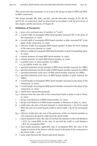
![16.1-159
Specification for Structural Steel Buildings, August 1, 2022
American Institute of Steel Construction
2. Rectangular HSS
2a. Effective Width for Connections to Rectangular HSS
For local yielding of transverse elements, the effective width of elements (plates or
rectangular HSS branches) perpendicular to the longitudinal axis of a rectangular
HSS member that deliver a force component transverse to the face of the member
shall be taken as
B
B t
F t
F t
B B
e
y
yb b
b b
=
≤
10
(K1-1)
For shear yielding (punching), the effective width of the face of a rectangular HSS
member, adjacent to the transverse element (plates or rectangular HSS branches)
shall be taken as
B
B t
B B
ep b b
=
≤
10
(K1-2)
User Note: Section J4 addresses the strength of affected elements in tension,
compression, flexure, and shear. The effective widths defined in this section are
used to establish the effective areas to be used when checking these limit states.
The Commentary provides further guidance.
3. Chord-Stress Interaction Parameter
Where required, the chord-stress interaction parameter, Qf, shall be taken as the fol-
lowing:
(a) For HSS chord member connecting surface in tension, Qf = 1
(b) For round HSS chord member connecting surface in compression
Qf = 1 − 0.3U(1 + U) ≤ 1.0 (K1-3)
(c) For rectangular HSS chord member connecting surface in compression
(1) For T-, Y-, cross-, and transverse plate connections
0 4 1 3 0 4 1 0
. . . .
≤ = −
≤
Q
U
f
β
(K1-4)
(2) For gapped K-connections
0 4 1 3 0 4 1 0
. . . .
≤ = −
≤
Q
U
f
eff
β
(K1-5)
(3) For longitudinal plate connections
Qf = 1 − 0.3U(1 + U) ≤ 1.0 (K1-3)
where
U
P
F A
M
F S
ro
c g
ro
c
= + ≤1 0
. (K1-6)
Sect. K1.] GENERAL PROVISIONS AND PARAMETERS FOR HSS CONNECTIONS
Part 16.1 J-N (121-194).indd 159
Part 16.1 J-N (121-194).indd 159 2023-01-10 8:06 PM
2023-01-10 8:06 PM](https://image.slidesharecdn.com/aisc360-22specificationforstructuralsteelbuildings-231108145904-1b416cfe/85/AISC-360-22-Specification-for-Structural-Steel-Buildings-pdf-227-320.jpg)
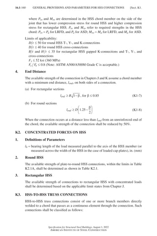
![16.1-161
Specification for Structural Steel Buildings, August 1, 2022
American Institute of Steel Construction
TABLE K2.1
Available Strengths of Plate-to-Round HSS
Connections
Connection Type Connection Available Strength Plate Bending
Transverse plate T-, Y-, and
cross-connections
Limit state: HSS local yielding
Plate axial load In-plane Out-of-plane
R F t
B
D
Q
n y
b
f
sinθ =
−
2 5 5
1 0 81
.
.
(K2-1a)
–
Mn = 0.5BbRn
(K2-1b)
f = 0.90 (LRFD) W = 1.67 (ASD)
Longitudinal plate T-, Y-, and
cross-connections
Limit state: HSS plastification
Plate axial load In-plane Out-of-plane
R F t
D
Q
n y
b
f
sinθ = +
5 5 1 0 25
2
. .
l
(K2-2a)
Mn = 0.8lbRn
(K2-2b)
–
f = 0.90 (LRFD) W = 1.67 (ASD)
TABLE K2.1A
Limits of Applicability of Table K2.1
HSS wall slenderness: D t ≤ 50 for T-connections under branch plate axial load or bending
D t ≤
40 for cross-connections under branch plate axial load or
bending
Width ratio: 0 2 1 0
. .
≤
B D
b
0 2 1 0
. .
≤
B D
b for transverse branch plate connections
Material strength: Fy ≤ 52 ksi (360 MPa)
Ductility: F F
y u ≤ 0.8 Note: ASTM A500/A500M Grade C is acceptable.
(a)
When the punching load, Pr sinθ, in a branch member is equilibrated by beam
shear in the chord member, the connection shall be classified as a T-connection
when the branch is perpendicular to the chord, and classified as a Y-connection
otherwise.
(b)
When the punching load, Pr sinθ, in a branch member is essentially equilibrated
(within 20%) by loads in other branch member(s) on the same side of the con-
nection, the connection shall be classified as a K-connection. The relevant gap is
between the primary branch members whose loads equilibrate.
User Note: A K-connection with one branch perpendicular to the chord is
often called an N-connection.
Sect. K3.] HSS-TO-HSS TRUSS CONNECTIONS
Part 16.1 J-N (121-194).indd 161
Part 16.1 J-N (121-194).indd 161 2023-01-10 8:06 PM
2023-01-10 8:06 PM](https://image.slidesharecdn.com/aisc360-22specificationforstructuralsteelbuildings-231108145904-1b416cfe/85/AISC-360-22-Specification-for-Structural-Steel-Buildings-pdf-229-320.jpg)
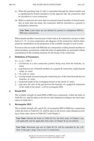
![16.1-163
Specification for Structural Steel Buildings, August 1, 2022
American Institute of Steel Construction
TABLE K3.1
Available Strengths of Round
HSS-to-HSS Truss Connections
Connection Type Connection Available Axial Strength
General check for T-, Y-, cross-, and
K-connections with gap, when
D D t
b (tens/comp) −
( )
2
Limit state: shear yielding (punching)
P F t D
n y b
=
+
0 6
1
2 2
. π
θ
θ
sin
sin
(K3-1)
f = 0.95 (LRFD) W = 1.58 (ASD)
T- and Y-connections Limit state: chord plastification
P F t Q
n y f
sinθ β γ
= +
( )
2 2 0 2
3 1 15 6
. . .
(K3-2)
f = 0.90 (LRFD) W = 1.67 (ASD)
Cross-connections Limit state: chord plastification
P F t Q
n y f
sinθ
β
=
−
2 5 7
1 0 81
.
.
(K3-3)
f = 0.90 (LRFD) W = 1.67 (ASD)
K-connections with gap or overlap Limit state: chord plastification
P
F t
D
D
n compression branch
y
b comp
sinθ
( )
= +
2 2 0 11 33
. .
Q Q
g f (K3-4)
P
P
n tension branch
n compression branch
sin
sin
θ
θ
( )
= ( )
(K3-5)
f = 0.90 (LRFD) W = 1.67 (ASD)
Functions
Q
g
t
g = +
−
+
γ
γ
0 2
1 2
1
0 024
0 5
1 33 1
.
.
.
.
.
exp
(K3-6)
Note that exp(x) is equal to ex, where e = 2.71828 is the base of the natural logarithm.
Sect. K3.] HSS-TO-HSS TRUSS CONNECTIONS
Part 16.1 J-N (121-194).indd 163
Part 16.1 J-N (121-194).indd 163 2023-01-10 8:06 PM
2023-01-10 8:06 PM](https://image.slidesharecdn.com/aisc360-22specificationforstructuralsteelbuildings-231108145904-1b416cfe/85/AISC-360-22-Specification-for-Structural-Steel-Buildings-pdf-231-320.jpg)
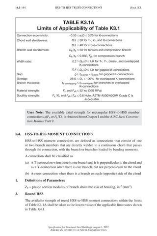
![16.1-165
Specification for Structural Steel Buildings, August 1, 2022
American Institute of Steel Construction
TABLE K3.2
Available Strengths of Rectangular
HSS-to-HSS Truss Connections
Connection Type Connection Available Axial Strength
Gapped K-Connections Limit state: chord wall plastification, for all b
P F t Q
n y eff f
sinθ β γ
= ( )
2 0 5
9 8
. . (K3-7)
f = 0.90 (LRFD) W = 1.67 (ASD)
Limit state: shear yielding (punching), when Bb B - 2t
This limit state need not be checked for square branches.
P F tB
n y eop
sinθ η β β
= + +
( )
0 6 2
. (K3-8)
f = 0.95 (LRFD) W = 1.58 (ASD)
Limit state: shear of chord side walls in the gap region
Determine Pnsinq in accordance with Section G4.
This limit state need not be checked for square chords.
Limit state: local yielding of branch/branches due to
uneven load distribution
This limit state need not be checked for square
branches or where B t ≥ 15.
P F t H B B t
n yb b b b e b
= + + −
( )
2 4 (K3-9)
f = 0.95 (LRFD) W = 1.58 (ASD)
Overlapped K-Connections
Note that the force arrows shown
for overlapped K-connections may
be reversed; i and j control member
identification.
Limit state: local yielding of branch/branches due to
uneven load distribution
f = 0.95 (LRFD) W = 1.58 (ASD)
When 25% ≤ Ov 50%
P F t
O
H t B B
n i ybi bi
v
bi bi eoi eov
, = −
( ) + +
50
2 4 (K3-10)
When 50% ≤ Ov 80%
P F t H t B B
n i ybi bi bi bi eoi eov
, = − + +
( )
2 4 (K3-11)
When 80% ≤ Ov ≤ 100%
P F t H t B B
n,i ybi bi bi bi bi eov
= − + +
( )
2 4 (K3-12)
B
B t
F t
F t
B B
eoi
y
ybi bi
bi bi
=
≤
10
(K3-13)
B
B t
F t
F t
B B
eov
bj bj
ybj bj
ybi bi
bi bi
=
≤
10
(K3-14)
Subscript i refers to the overlapping branch.
Subscript j refers to the overlapped branch.
P P
F A
F A
n,j n,i
ybj bj
ybi bi
=
(K3-15)
Functions
βeff b b compression branch
mp b b tension branch
B H B H B
= +
( ) + +
( )
4 (K3-16)
βeop
ep
B
B
=
(K3-17)
Sect. K4.] HSS-TO-HSS MOMENT CONNECTIONS
Part 16.1 J-N (121-194).indd 165
Part 16.1 J-N (121-194).indd 165 2023-01-10 8:06 PM
2023-01-10 8:06 PM](https://image.slidesharecdn.com/aisc360-22specificationforstructuralsteelbuildings-231108145904-1b416cfe/85/AISC-360-22-Specification-for-Structural-Steel-Buildings-pdf-233-320.jpg)
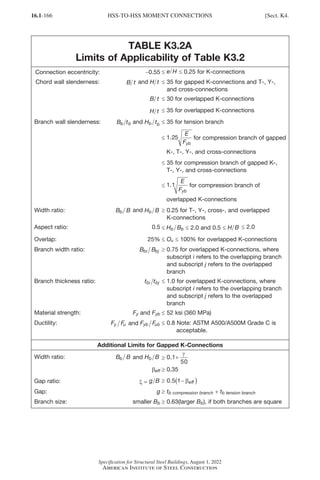
![16.1-167
Specification for Structural Steel Buildings, August 1, 2022
American Institute of Steel Construction
TABLE K4.1
Available Strengths of Round HSS-to-HSS
Moment Connections
Connection Type Connection Available Flexural Strength
Branch(es) under in-plane bending
T-, Y-, and cross-connections
Limit state: chord plastification
M F t
D
Q
n ip y
b
f
-
sin
=
5 39 2 0 5
. .
γ β
θ
(K4-1)
f = 0.90 (LRFD) W = 1.67 (ASD)
Limit state: shear yielding (punching),
when D D t
b −
( )
2
M F tD
n ip y b
-
sin
sin
=
+
0 6
1 3
4
2
2
.
θ
θ
(K4-2)
f = 0.95 (LRFD) W = 1.58 (ASD)
Branch(es) under out-of-plane bending
T-, Y-, and cross-connections
Limit state: chord plastification
M
F t D
Q
n op
y b
f
-
sin
=
−
2
3 0
1 0 81
θ β
.
.
(K4-3)
f = 0.90 (LRFD) W = 1.67 (ASD)
Limit state: shear yielding (punching),
when D D t
b −
( )
2
M F tD
n op y b
-
sin
sin
=
+
0 6
3
4
2
2
.
θ
θ
(K4-4)
f = 0.95 (LRFD) W = 1.58 (ASD)
For T-, Y-, and cross-connections, with branch(es) under combined axial load, in-plane bend-
ing, and out-of-plane bending, or any combination of these load effects
P
P
M
M
M
M
r
c
r ip
c ip
r op
c op
+
+ ≤
-
-
-
-
2
1.0 (K4-5)
Pr = required axial strength in branch using LRFD or ASD load combinations, kips (N)
Mr-ip =
required in-plane flexural strength in branch using LRFD or ASD load combinations,
kip-in. (N-mm)
Mr-op =
required out-of-plane flexural strength in branch using LRFD or ASD load
combinations, kip-in. (N-mm)
Pc = available axial strength obtained from Table K3.1, kips (N)
Mc-ip = available strength for in-plane bending, kip-in. (N-mm)
Mc-op = available strength for out-of-plane bending, kip-in. (N-mm)
Sect. K4.] HSS-TO-HSS MOMENT CONNECTIONS
Part 16.1 J-N (121-194).indd 167
Part 16.1 J-N (121-194).indd 167 2023-09-24 10:50 PM
2023-09-24 10:50 PM](https://image.slidesharecdn.com/aisc360-22specificationforstructuralsteelbuildings-231108145904-1b416cfe/85/AISC-360-22-Specification-for-Structural-Steel-Buildings-pdf-235-320.jpg)
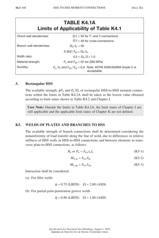
![16.1-169
Specification for Structural Steel Buildings, August 1, 2022
American Institute of Steel Construction
TABLE K4.2
Available Strengths of Rectangular HSS-to-HSS
Moment Connections
Connection Type Connection Available Flexural Strength
Branch(es) under out-of-plane bending
T- and cross-connections
Limit state: chord sidewall local yielding
M F t B t H t
n op y b
- = −
( ) +
( )
* 5 (K4-6)
f = 1.00 (LRFD) W = 1.50 (ASD)
Limit state: chord distortional failure, for
T-connections and unbalanced cross-connections
M F t H t BHt B H
n op y b
- = + +
( )
2 (K4-7)
f = 0.95 (LRFD) W = 1.58 (ASD)
Branch(es) under in-plane bending
T- and cross-connections
Limit state: sidewall local yielding
When b ≥ 0.85
M F t H t
n ip y b
- = +
( )
0 5 5
2
. * (K4-8)
f = 1.00 (LRFD) W = 1.50 (ASD)
For T- and cross-connections, with branch(es) under combined axial load, in-plane bending,
and out-of-plane bending, or any combination of these load effects
P
P
M
M
M
M
r
c
r ip
c ip
r op
c op
+ + ≤
-
-
-
-
1.0 (K4-9)
Pr = required axial strength in branch using LRFD or ASD load combinations, kips (N)
Mr-ip =
required in-plane flexural strength in branch using LRFD or ASD load combinations,
kip-in. (N-mm)
Mr-op =
required out-of-plane flexural strength in branch using LRFD or ASD load combina-
tions, kip-in. (N-mm)
Pc = available axial strength, kips (N)
Mc-ip = available strength for in-plane bending, kip-in. (N-mm)
Mc-op = available strength for out-of-plane bending, kip-in. (N-mm)
= fMn-op (LRFD); = Mn op
- Ω (ASD)
Functions
Fy
* = Fy for T-connections and 0.8Fy for cross-connections
Pro = Pu for LRFD, and Pa for ASD; Mro = Mu for LRFD, and Ma for ASD
Sect. K5.] WELDS OF PLATES AND BRANCHES TO HSS
Part 16.1 J-N (121-194).indd 169
Part 16.1 J-N (121-194).indd 169 2023-01-29 12:11 PM
2023-01-29 12:11 PM](https://image.slidesharecdn.com/aisc360-22specificationforstructuralsteelbuildings-231108145904-1b416cfe/85/AISC-360-22-Specification-for-Structural-Steel-Buildings-pdf-237-320.jpg)
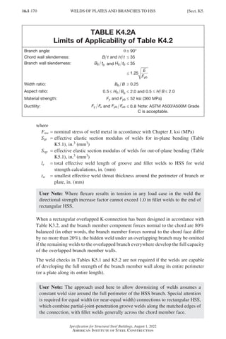
![16.1-171
Specification for Structural Steel Buildings, August 1, 2022
American Institute of Steel Construction
TABLE K5.1
Effective Weld Properties for Connections to
Rectangular HSS
Connection Type Weld Properties
Transverse plate T- and cross-
connections under plate axial load
Effective weld properties
le e
B
= 2 (K5-4)
where le = total effective weld length for welds on
both sides of the transverse plate, in. (mm)
T-, Y-, and cross-connections
under branch axial load or bending
Effective weld properties
le
b
e
H
B
= +
2
2
sinθ
(K5-5)
S
t H
t B
H
ip
w b
w e
b
=
+
3
2
sin sin
θ θ
(K5-6)
S t
H
B
t
B
t B B
B
op w
b
b
w
b
w b e
b
=
+ ( )−
( ) −
( )
sinθ 3
3
2
3
(K5-7)
When b 0.85 or q 50°, Be 2 shall not exceed
Bb 4.
Gapped K-connections under branch
axial load
Effective weld properties
When q ≤ 50°
le
b b
b b
H t
B t
=
−
( ) + −
( )
2 1 2
2 1 2
.
.
sinθ
(K5-8)
When q ≥ 60°
le
b b
b b
H t
B t
=
−
( ) + −
2 1 2
1 2
.
.
sinθ
(K5-9)
When 50° q 60°, linear interpolation shall be
used to determine le.
Sect. K5.] WELDS OF PLATES AND BRANCHES TO HSS
Part 16.1 J-N (121-194).indd 171
Part 16.1 J-N (121-194).indd 171 2023-01-10 8:06 PM
2023-01-10 8:06 PM](https://image.slidesharecdn.com/aisc360-22specificationforstructuralsteelbuildings-231108145904-1b416cfe/85/AISC-360-22-Specification-for-Structural-Steel-Buildings-pdf-239-320.jpg)
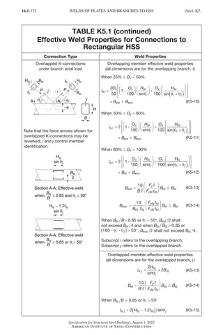
![16.1-173
Specification for Structural Steel Buildings, August 1, 2022
American Institute of Steel Construction
TABLE K5.2
Effective Weld Properties for Connections to
Round HSS
Connection Type Weld Properties
T-, Y-, and cross-connections under
branch axial load
Effective weld properties
When 0.1≤ b ≤ 0.5, 60° ≤ q ≤ 90°, and
10 ≤ D t ≤ 50
l l l
e w w
D t
=
( )
≤
4
2β
(K5-16)
where lw is the total weld length around
the branch. This may be obtained from 3D
models of intersection cylinders, or from
lw b
D
=
+
π
θ
1 1
2
sin
(K5-17)
Sect. K5.] WELDS OF PLATES AND BRANCHES TO HSS
Part 16.1 J-N (121-194).indd 173
Part 16.1 J-N (121-194).indd 173 2023-01-10 8:06 PM
2023-01-10 8:06 PM](https://image.slidesharecdn.com/aisc360-22specificationforstructuralsteelbuildings-231108145904-1b416cfe/85/AISC-360-22-Specification-for-Structural-Steel-Buildings-pdf-241-320.jpg)
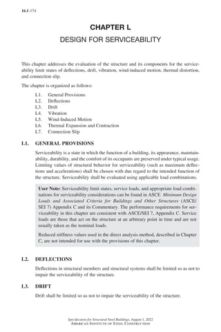
![16.1-175
Specification for Structural Steel Buildings, August 1, 2022
American Institute of Steel Construction
L4. VIBRATION
The effect of vibration on the comfort of the occupants and the function of the struc-
ture shall be considered. The sources of vibration to be considered include occupant
loading, vibrating machinery, and others identified for the structure.
L5. WIND-INDUCED MOTION
The effect of wind-induced motion of buildings on the comfort of occupants shall
be considered.
L6. THERMAL EXPANSION AND CONTRACTION
The effects of thermal expansion and contraction of a building shall be considered.
L7. CONNECTION SLIP
The effects of connection slip shall be included in the design where slip at bolted
connections may cause deformations that impair the serviceability of the structure.
Where appropriate, the connection shall be designed to preclude slip.
User Note: For the design of slip-critical connections, see Sections J3.9 and
J3.10. For more information on connection slip, refer to the RCSC Specification
for Structural Joints Using High-Strength Bolts.
Sect. L7.] CONNECTION SLIP
Part 16.1 J-N (121-194).indd 175
Part 16.1 J-N (121-194).indd 175 2023-01-10 8:06 PM
2023-01-10 8:06 PM](https://image.slidesharecdn.com/aisc360-22specificationforstructuralsteelbuildings-231108145904-1b416cfe/85/AISC-360-22-Specification-for-Structural-Steel-Buildings-pdf-243-320.jpg)
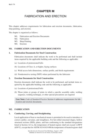
![16.1-177
Specification for Structural Steel Buildings, August 1, 2022
American Institute of Steel Construction
not exceed 1,100°F (590°C) and for ASTM A709/A709M, ASTM A913/A913M,
and ASTM A1066/A1066M, the temperature shall not exceed the maximum as
specified in the corresponding ASTM material standard. Subject to the approval of
the engineer of record, alternative temperature limitations in accordance with recom-
mendations by the producer of the material shall be used.
User Note: For other materials, as identified in Section A3.1b, limitations for the
temperature of the heated regions should be consistent with the recommendations
of the producer of the material.
2. Thermal Cutting
Thermally cut edges shall meet the requirements of Structural Welding Code—Steel
(AWS D1.1/D1.1M) clauses 7.14.5.2, 7.14.8.3, and 7.14.8.4, hereafter referred to as
AWS D1.1/D1.1M, with the exception that thermally cut free edges that will not be
subject to fatigue shall be free of round-bottom gouges greater than x in. (5 mm)
deep and sharp V-shaped notches. Gouges deeper than x in. (5 mm) and notches
shall be removed by grinding or repaired by welding.
Reentrant corners shall be formed with a curved transition. The radius need not
exceed that required to fit the connection. Discontinuous corners are permitted where
the material on both sides of the discontinuous reentrant corner is connected to a
mating piece to prevent deformation and associated stress concentration at the corner.
User Note: Reentrant corners with a radius of 2 to a in. (13 to 10 mm) are
generally acceptable for statically loaded work. Where pieces need to fit tightly
together, a discontinuous reentrant corner is acceptable if the pieces are connected
close to the corner on both sides of the discontinuous corner. Slots in HSS for
gussets may be made with semicircular ends or with curved corners. Square ends
are acceptable provided the edge of the gusset is welded to the HSS.
Weld access holes shall meet the geometrical requirements of Section J1.6. Beam
copes and weld access holes in shapes that are to be galvanized shall be ground to
bright metal. For shapes with a flange thickness not exceeding 2 in. (50 mm), the
roughness of thermally cut surfaces of copes shall be no greater than a surface rough-
ness value of 2,000 µin. (50 µm) as defined in Surface Texture, Surface Roughness,
Waviness, and Lay (ASME B46.1), hereafter referred to as ASME B46.1. For beam
copes and weld access holes in which the curved part of the access hole is thermally
cut in ASTM A6/A6M hot-rolled shapes with a flange thickness exceeding 2 in. (50
mm) and welded built-up shapes with material thickness greater than 2 in. (50 mm),
a preheat temperature of not less than 150°F (66°C) shall be applied prior to thermal
cutting. The thermally cut surface of access holes in ASTM A6/A6M hot-rolled
shapes with a flange thickness exceeding 2 in. (50 mm) and built-up shapes with a
material thickness greater than 2 in. (50 mm) shall be ground.
User Note: The AWS Surface Roughness Guide for Oxygen Cutting (AWS C4.1-
77) sample 2 may be used as a guide for evaluating the surface roughness of copes
in shapes with flanges not exceeding 2 in. (50 mm) thick.
Sect. M2.] FABRICATION
Part 16.1 J-N (121-194).indd 177
Part 16.1 J-N (121-194).indd 177 2023-01-10 8:06 PM
2023-01-10 8:06 PM](https://image.slidesharecdn.com/aisc360-22specificationforstructuralsteelbuildings-231108145904-1b416cfe/85/AISC-360-22-Specification-for-Structural-Steel-Buildings-pdf-245-320.jpg)
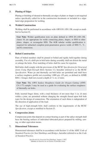
![16.1-179
Specification for Structural Steel Buildings, August 1, 2022
American Institute of Steel Construction
8. Finish of Column Bases
Column bases and base plates shall be finished in accordance with the following
requirements:
(a)
Steel bearing plates 2 in. (50 mm) or less in thickness are permitted without mill-
ing provided a smooth and notch-free contact bearing surface is obtained. Steel
bearing plates over 2 in. (50 mm) but not over 4 in. (100 mm) in thickness are
permitted to be straightened by pressing or, if presses are not available, by mill-
ing for bearing surfaces, except as stipulated in subparagraphs (b) and (c) of this
section, to obtain a smooth and notch-free contact bearing surface. Steel bearing
plates over 4 in. (100 mm) in thickness shall be milled for bearing surfaces,
except as stipulated in subparagraphs (b) and (c) of this section.
(b)
Bottom surfaces of bearing plates and column bases that are grouted to ensure
full bearing contact on foundations need not be milled.
(c)
Top surfaces of bearing plates need not be milled when complete-joint-penetra-
tion groove welds are provided between the column and the bearing plate.
9. Holes for Anchor Rods
Holes for anchor rods are permitted to be mechanically or manually thermally cut,
provided the quality requirements in accordance with the provisions of Section M2.2
are met.
10. Drain Holes
When water can collect inside HSS or box members, either during construction or
during service, the member shall be sealed, provided with a drain hole at the base, or
otherwise protected from water infiltration.
11. Requirements for Galvanized Members
Members and parts to be galvanized shall be designed, detailed, and fabricated to
provide for flow and drainage of pickling fluids and zinc and to prevent pressure
buildup in enclosed parts.
User Note: Drainage and vent holes should be detailed on fabrication documents.
See the American Galvanizers Association (AGA) The Design of Products to be
Hot-Dip Galvanized After Fabrication, and ASTM A123, ASTM A143/A143M,
ASTM A385/A385M, ASTM F2329/F2329M, and ASTM A780/A780M for use-
ful information on design and detailing of galvanized members. See Section M2.2
for requirements for copes of members that are to be galvanized.
M3. SHOP PAINTING
1. General Requirements
Shop painting and surface preparation shall be in accordance with the provisions in
Code of Standard Practice Section 6.
Shop paint is not required unless specified by the contract documents.
Sect. M3.] SHOP PAINTING
Part 16.1 J-N (121-194).indd 179
Part 16.1 J-N (121-194).indd 179 2023-02-14 6:01 PM
2023-02-14 6:01 PM](https://image.slidesharecdn.com/aisc360-22specificationforstructuralsteelbuildings-231108145904-1b416cfe/85/AISC-360-22-Specification-for-Structural-Steel-Buildings-pdf-247-320.jpg)
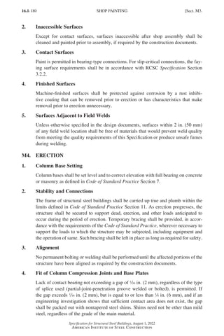
![16.1-181
Specification for Structural Steel Buildings, August 1, 2022
American Institute of Steel Construction
5. Field Welding
Surfaces in and adjacent to joints to be field welded shall be prepared as necessary to
assure weld quality. This preparation shall include surface preparation necessary to
correct for damage or contamination occurring subsequent to fabrication.
6. Field Painting
Responsibility for touch-up painting, cleaning, and field painting shall be allocated
in accordance with accepted local practices, and this allocation shall be set forth
explicitly in the contract documents.
Sect. M4.] ERECTION
Part 16.1 J-N (121-194).indd 181
Part 16.1 J-N (121-194).indd 181 2023-01-10 8:06 PM
2023-01-10 8:06 PM](https://image.slidesharecdn.com/aisc360-22specificationforstructuralsteelbuildings-231108145904-1b416cfe/85/AISC-360-22-Specification-for-Structural-Steel-Buildings-pdf-249-320.jpg)
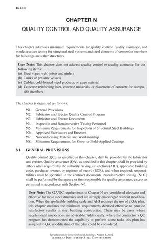
![16.1-183
Specification for Structural Steel Buildings, August 1, 2022
American Institute of Steel Construction
User Note: The producers of materials manufactured in accordance with the stan-
dard specifications referenced in Section A3 and steel deck manufacturers are not
considered to be fabricators or erectors.
N2. FABRICATOR AND ERECTOR QUALITY CONTROL PROGRAM
The fabricator and erector shall establish, maintain, and implement QC procedures
to ensure that their work is performed in accordance with this Specification and the
construction documents.
1. Material Identification
Material identification procedures shall comply with the requirements of Section 6.1
of the AISC Code of Standard Practice for Steel Buildings and Bridges, hereafter
referred to as the Code of Standard Practice, and shall be monitored by the fabrica-
tor’s quality control inspector (QCI).
2. Fabricator Quality Control Procedures
The fabricator’s QC procedures shall address inspection of the following as a mini-
mum, as applicable:
(a) Shop welding, high-strength bolting, and details in accordance with Section N5
(b) Shop cut and finished surfaces in accordance with Section M2
(c)
Shop heating for cambering, curving, and straightening in accordance with
Section M2.1
(d)
Tolerances for shop fabrication in accordance with Code of Standard Practice
Section 11.2
3. Erector Quality Control Procedures
The erector’s quality control procedures shall address inspection of the following as
a minimum, as applicable:
(a) Field welding, high-strength bolting, and details in accordance with Section N5
(b)
Steel deck in accordance with Standard for Quality Control and Quality Assur-
ance for Installation of Steel Deck (ANSI/SDI QA/QC)
(c)
Headed steel stud anchor placement and attachment in accordance with Section
N5.4
(d) Field cut surfaces in accordance with Section M2.2
(e) Field heating for straightening in accordance with Section M2.1
(f)
Tolerances for field erection in accordance with Code of Standard Practice
Section 11.3
Sect. N2.] FABRICATOR AND ERECTOR QUALITY CONTROL PROGRAM
Part 16.1 J-N (121-194).indd 183
Part 16.1 J-N (121-194).indd 183 2023-01-10 8:06 PM
2023-01-10 8:06 PM](https://image.slidesharecdn.com/aisc360-22specificationforstructuralsteelbuildings-231108145904-1b416cfe/85/AISC-360-22-Specification-for-Structural-Steel-Buildings-pdf-251-320.jpg)
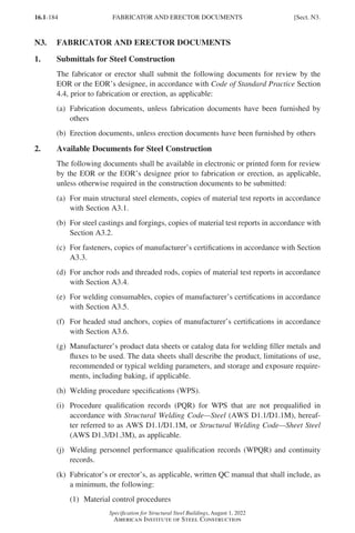
![16.1-185
Specification for Structural Steel Buildings, August 1, 2022
American Institute of Steel Construction
(2) Inspection procedures
(3) Nonconformance procedures
(l)
Fabricator’s or erector’s, as applicable, QCI qualifications.
(m) Fabricator NDT personnel qualifications, if NDT is performed by the fabricator.
N4. INSPECTION AND NONDESTRUCTIVE TESTING PERSONNEL
1. Quality Control Inspector Qualifications
QC welding inspection personnel shall be qualified to the satisfaction of the fabrica-
tor’s or erector’s QC program, as applicable, and in accordance with either of the
following:
(a)
Associate welding inspectors (AWI) or higher as defined in Standard for the
Qualification of Welding Inspectors (AWS B5.1), or
(b)
Qualified under the provisions of AWS D1.1/D1.1M, clause 8.1.4.2(5).
QC bolting inspection personnel shall be qualified on the basis of documented train-
ing and experience in structural bolting inspection.
The fabricator’s or erector’s QCI performing coating inspection shall be qualified by
training and experience as required by the firm’s quality control program. The QCI
shall receive initial and periodic documented training.
2. Quality Assurance Inspector Qualifications
QA welding inspectors shall be qualified to the satisfaction of the QA agency’s writ-
ten practice, and in accordance with either of the following:
(a)
Welding inspectors (WI) or senior welding inspectors (SWI), as defined in
Standard for the Qualification of Welding Inspectors (AWS B5.1), except AWI
are permitted to be used under the direct supervision of WI, who are on the
premises and available when weld inspection is being conducted, or
(b)
Qualified under the provisions of AWS D1.1/D1.1M, clause 8.1.4.2(5).
QA bolting inspection personnel shall be qualified on the basis of documented train-
ing and experience in structural bolting inspection.
QA coating inspection personnel shall be qualified to the satisfaction of the QA
agency’s written practice. The inspector shall have received documented training,
have experience in coating inspection, and shall be qualified in accordance with one
of the following:
(a) AMPP Coating Inspector Program (CIP) Level 1 Certification
(b) NACE Coating Inspector Program (CIP) Level 1 Certification
(c)
SSPC Protective Coatings Inspector Program (PCI) Level 1 Certification
(d)
On the basis of documented training and experience in coating application and
inspection
Sect. N4.] INSPECTION AND NONDESTRUCTIVE TESTING PERSONNEL
Part 16.1 J-N (121-194).indd 185
Part 16.1 J-N (121-194).indd 185 2023-09-24 10:50 PM
2023-09-24 10:50 PM](https://image.slidesharecdn.com/aisc360-22specificationforstructuralsteelbuildings-231108145904-1b416cfe/85/AISC-360-22-Specification-for-Structural-Steel-Buildings-pdf-253-320.jpg)
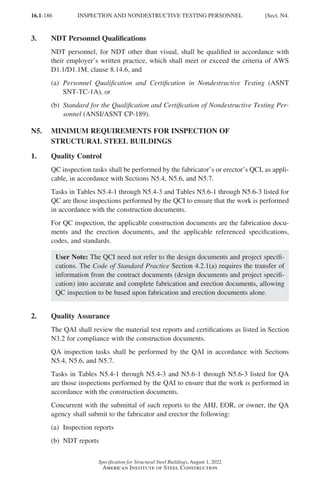
![16.1-187
Specification for Structural Steel Buildings, August 1, 2022
American Institute of Steel Construction
Table N5.4-1
Inspection Tasks Prior to Welding
Inspection Tasks Prior to Welding QC QA
Welder qualification records and continuity records P O
WPS available P P
Manufacturer certifications for welding consumables available P P
Material identification (type/grade) O O
Welder identification system
•
Fabricator or erector, as applicable, shall maintain a system
by which a welder who has welded a joint or member can be
identified.
•
Die stamping of members subjected to fatigue shall be
prohibited unless approved by the engineer of record.
O O
Fit-up of groove welds (including joint geometry)
• Joint preparations
• Dimensions (alignment, root opening, root face, bevel)
• Cleanliness (condition of steel surfaces)
• Tacking (tack weld quality and location)
• Backing type and fit (if applicable)
O O
Fit-up of CJP groove welds of HSS T-, Y-, and K-connections with-
out backing (including joint geometry)
• Joint preparations
• Dimensions (alignment, root opening, root face, bevel)
• Cleanliness (condition of steel surfaces)
• Tacking (tack weld quality and location)
P O
Configuration and finish of access holes O O
Fit-up of fillet welds
• Dimensions (alignment, gaps at root)
• Cleanliness (condition of steel surfaces)
• Tacking (tack weld quality and location)
O O
Check welding equipment O −
3. Coordinated Inspection
When a task is noted to be performed by both QC and QA, it is permitted to coor-
dinate the inspection function between the QCI and QAI so that the inspection
functions are performed by only one party. When QA relies upon inspection func-
tions performed by QC, the approval of the EOR and the AHJ is required.
4. Inspection of Welding
Observation of welding operations and visual inspection of in-process and completed
welds shall be the primary method to confirm that the materials, procedures, and
workmanship are in conformance with the construction documents.
Sect. N5.] MINIMUM REQUIREMENTS FOR INSPECTION
Part 16.1 J-N (121-194).indd 187
Part 16.1 J-N (121-194).indd 187 2023-01-10 8:06 PM
2023-01-10 8:06 PM](https://image.slidesharecdn.com/aisc360-22specificationforstructuralsteelbuildings-231108145904-1b416cfe/85/AISC-360-22-Specification-for-Structural-Steel-Buildings-pdf-255-320.jpg)
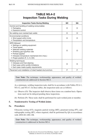
![16.1-189
Specification for Structural Steel Buildings, August 1, 2022
American Institute of Steel Construction
TABLE N5.4-3
Inspection Tasks After Welding
Inspection Tasks After Welding QC QA
Welds cleaned O O
Size, length, and location of welds P P
Welds meet visual acceptance criteria
• Crack prohibition
• Weld/base-metal fusion
• Crater cross section
• Weld profiles
• Weld size
• Undercut
• Porosity
P P
Arc strikes P P
k-area[a] P P
Weld access holes in rolled heavy shapes and built-up heavy
shapes[b] P P
Backing removed and weld tabs removed (if required) P P
Repair activities P P
Document acceptance or rejection of welded joint or member[c] P P
No prohibited welds have been added without the approval of the
engineer of record
O O
[a]
When welding of doubler plates, continuity plates, or stiffeners has been performed in the k-area, visually
inspect the web k-area for cracks within 3 in. (75 mm) of the weld.
[b]
After rolled heavy shapes (see Section A3.1d) and built-up heavy shapes (see Section A3.1e) are welded,
visually inspect the weld access hole for cracks.
[c]
Die stamping of members subjected to fatigue shall be prohibited unless approved by the engineer of record.
5b. CJP Groove Weld NDT
For structures in risk category III or IV, as defined in ASCE/SEI 7, UT shall be
performed by QA on all complete-joint-penetration (CJP) groove welds subjected to
transversely applied tension loading in butt, T-, and corner joints, in material c in.
(8 mm) thick or greater. For structures in risk category II, UT shall be performed by
QA on 10% of CJP groove welds in butt, T-, and corner joints subjected to trans-
versely applied tension loading, in materials c in. (8 mm) thick or greater.
User Note: For structures in risk category I, NDT of CJP groove welds is not
required. For all structures in all risk categories, NDT of CJP groove welds in
materials less than c in. (8 mm) thick is not required.
5c. Welded Joints Subjected to Fatigue
When required by Appendix 3, Table A-3.1, welded joints requiring weld soundness
to be established by radiographic or ultrasonic inspection shall be tested by QA as
prescribed. Reduction in the rate of UT is prohibited.
Sect. N5.] MINIMUM REQUIREMENTS FOR INSPECTION
Part 16.1 J-N (121-194).indd 189
Part 16.1 J-N (121-194).indd 189 2023-01-10 8:06 PM
2023-01-10 8:06 PM](https://image.slidesharecdn.com/aisc360-22specificationforstructuralsteelbuildings-231108145904-1b416cfe/85/AISC-360-22-Specification-for-Structural-Steel-Buildings-pdf-257-320.jpg)
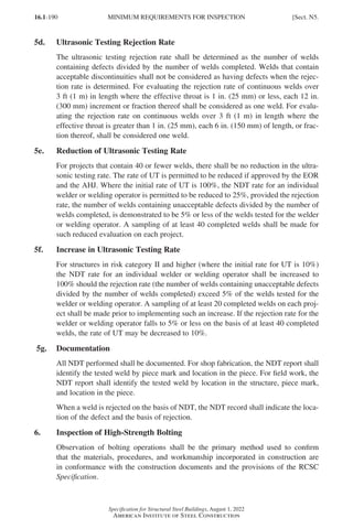
![16.1-191
Specification for Structural Steel Buildings, August 1, 2022
American Institute of Steel Construction
TABLE N5.6-1
Inspection Tasks Prior to Bolting
Inspection Tasks Prior to Bolting QC QA
Manufacturer’s certifications available for fastener materials O P
Fasteners marked in accordance with ASTM requirements O O
Correct fasteners selected for the joint detail (grade, type, bolt
length if threads are to be excluded from shear plane)
O O
Correct bolting procedure selected for joint detail O O
Connecting elements, including the appropriate faying surface
condition and hole preparation, if specified, meet applicable
requirements
O O
Pre-installation verification testing by installation personnel
observed and documented for fastener assemblies and methods
used
P O
Protected storage provided for bolts, nuts, washers, and other
fastener components
O O
(a)
For snug-tight joints, pre-installation verification testing as specified in Table
N5.6-1 and monitoring of the installation procedures as specified in Table
N5.6-2 are not applicable. The QCI and QAI need not be present during the
installation of fasteners in snug-tight joints.
(b)
For pretensioned joints and slip-critical joints, when the installer is using the
turn-of-nut or combined method with matchmarking techniques, the direct-
tension-indicator method, or the twist-off-type tension control bolt method,
monitoring of bolt pretensioning procedures shall be as specified in Table N5.6-
2. The QCI and QAI need not be present during the installation of fasteners when
these methods are used by the installer.
(c)
For pretensioned joints and slip-critical joints, when the installer is using the
turn-of-nut or combined method without matchmarking, or the calibrated wrench
method, monitoring of bolt pretensioning procedures shall be as specified in
Table N5.6-2. The QCI and QAI shall be engaged in their assigned inspec-
tion duties during installation of fasteners when these methods are used by the
installer.
As a minimum, bolting inspection tasks shall be in accordance with Tables N5.6-1,
N5.6-2, and N5.6-3. In these tables, the inspection tasks are as follows:
(a)
Observe (O): The inspector shall observe these items on a random basis.
Operations need not be delayed pending these inspections.
(b) Perform (P): These tasks shall be performed for each bolted connection.
Sect. N5.] MINIMUM REQUIREMENTS FOR INSPECTION
Part 16.1 J-N (121-194).indd 191
Part 16.1 J-N (121-194).indd 191 2023-01-10 8:06 PM
2023-01-10 8:06 PM](https://image.slidesharecdn.com/aisc360-22specificationforstructuralsteelbuildings-231108145904-1b416cfe/85/AISC-360-22-Specification-for-Structural-Steel-Buildings-pdf-259-320.jpg)
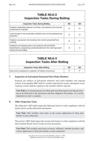
![16.1-193
Specification for Structural Steel Buildings, August 1, 2022
American Institute of Steel Construction
The QAI shall be on the premises for inspection during the placement of anchor rods
and other embedments supporting structural steel for compliance with the construc-
tion documents. As a minimum, the diameter, grade, type, and length of the anchor
rod or embedded item, and the extent or depth of embedment into the concrete, shall
be verified and documented prior to placement of concrete.
The QAI shall inspect the fabricated steel or erected steel frame, as applicable, to
verify compliance with the details shown on the construction documents.
User Note: This includes such items as braces, stiffeners, member locations, and
the correct application of joint details at each connection.
The acceptance or rejection of joint details and the correct application of joint details
shall be documented.
N6. APPROVED FABRICATORS AND ERECTORS
When the fabricator or erector has been approved by the AHJ to perform all inspec-
tions without the involvement of a third-party, independent QAI, the fabricator
or erector shall perform and document all of the QA inspections required by this
chapter.
NDT of welds completed in an approved fabricator’s shop is permitted to be per-
formed by that fabricator when approved by the AHJ. When the fabricator performs
the NDT, the NDT reports prepared by the fabricator’s NDT personnel shall be avail-
able for review by the QA agency.
At completion of fabrication, the approved fabricator shall submit a certificate of
compliance to the AHJ stating that the materials supplied and work performed by the
fabricator are in accordance with the construction documents. At completion of erec-
tion, the approved erector shall submit a certificate of compliance to the AHJ stating
that the materials supplied and work performed by the erector are in accordance with
the construction documents.
N7. NONCONFORMING MATERIAL AND WORKMANSHIP
Identification and rejection of material or workmanship that is not in conformance
with the construction documents is permitted at any time during the progress of the
work. However, this provision shall not relieve the owner or the inspector of the
obligation for timely, in-sequence inspections. Nonconforming material and work-
manship shall be brought to the immediate attention of the fabricator or erector, as
applicable.
Nonconforming material or workmanship shall be brought into conformance or made
suitable for its intended purpose as determined by the EOR.
Concurrent with the submittal of such reports to the AHJ, EOR, or owner, the QA
agency shall submit to the fabricator and erector:
(a) Nonconformance reports
(b) Reports of repair, replacement, or acceptance of nonconforming items
Sect. N7.] NONCONFORMING MATERIAL AND WORKMANSHIP
Part 16.1 J-N (121-194).indd 193
Part 16.1 J-N (121-194).indd 193 2023-01-10 8:06 PM
2023-01-10 8:06 PM](https://image.slidesharecdn.com/aisc360-22specificationforstructuralsteelbuildings-231108145904-1b416cfe/85/AISC-360-22-Specification-for-Structural-Steel-Buildings-pdf-261-320.jpg)
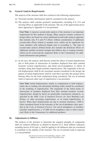
![16.1-197
Specification for Structural Steel Buildings, August 1, 2022
American Institute of Steel Construction
User Note: Stiffness reduction should be applied to all member properties includ-
ing torsional properties (GJ and ECw) affecting twist of the member cross section.
One practical method of including stiffness reduction is to reduce E and G by
0.8τb, thereby leaving all cross-section geometric properties at their nominal
value.
Applying this stiffness reduction to some members and not others can, in some
cases, result in artificial distortion of the structure under load and thereby lead
to an unintended redistribution of forces. This can be avoided by applying the
reduction to all members, including those that do not contribute to the stability
of the structure.
3. Calculation of Available Strengths
For design using a second-order elastic analysis that includes the direct modeling of
system and member imperfections, the available strengths of members and connec-
tions shall be calculated in accordance with the provisions of Chapters D through
K, as applicable, except as defined below, with no further consideration of overall
structure stability.
The nominal compressive strength of members, Pn, may be taken as the cross-section
compressive strength, FyAg, or as FyAe for members with slender elements, where Ae
is as defined in Section E7.
1.3. DESIGN BY INELASTIC ANALYSIS
User Note: Design by the provisions of this section is independent of the require-
ments of Section 1.2.
1. General Requirements
The design strength of the structural system and its members and connections shall
equal or exceed the required strength as determined by the inelastic analysis. The
provisions of Section 1.3 do not apply to seismic design.
The inelastic analysis shall take into account (a) flexural, shear, axial, and torsional
member deformations, and all other component and connection deformations that
contribute to the displacements of the structure; (b) second-order effects (including
P-∆, P-δ, and twisting effects); (c) geometric imperfections; (d) stiffness reductions
due to inelasticity, including partial yielding of the cross section that may be accentu-
ated by the presence of residual stresses; and (e) uncertainty in system, member, and
connection strength and stiffness.
Strength limit states detected by an inelastic analysis that incorporates all of the pre-
ceding requirements in this section are not subject to the corresponding provisions of
this Specification when a comparable or higher level of reliability is provided by the
analysis. Strength limit states not detected by the inelastic analysis shall be evaluated
using the corresponding provisions of Chapters D through K.
App. 1.3.] DESIGN BY INELASTIC ANALYSIS
Part 16.1 Appendix A1-A4 (195-266).indd 197
Part 16.1 Appendix A1-A4 (195-266).indd 197 2023-01-10 8:25 PM
2023-01-10 8:25 PM](https://image.slidesharecdn.com/aisc360-22specificationforstructuralsteelbuildings-231108145904-1b416cfe/85/AISC-360-22-Specification-for-Structural-Steel-Buildings-pdf-265-320.jpg)
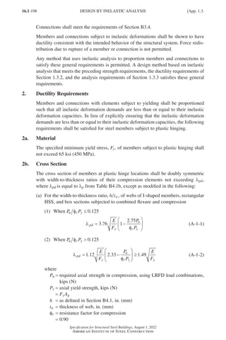
![16.1-199
Specification for Structural Steel Buildings, August 1, 2022
American Institute of Steel Construction
(b)
For the width-to-thickness ratio, b t, of flanges of rectangular HSS and box
sections, and for flange cover plates between lines of fasteners or welds
λ pd y
E F
.
= 94
0 (A-1-3)
where
b = as defined in Section B4.1, in. (mm)
t = as defined in Section B4.1, in. (mm)
(c)
For the diameter-to-thickness ratio, D t, of round HSS in flexure
λ pd y
E F
.
= 45
0 0 (A-1-4)
where
D = outside diameter of round HSS, in. (mm)
2c. Unbraced Length
In prismatic member segments that contain plastic hinges, the laterally unbraced
length, Lb, shall not exceed Lpd, determined as follows. For members subjected to
flexure only, or to flexure and axial tension, Lb shall be taken as the length between
points braced against lateral displacement of the compression flange, or between
points braced to prevent twist of the cross section. For members subjected to flexure
and axial compression, Lb shall be taken as the length between points braced against
both lateral displacement in the minor-axis direction and twist of the cross section.
(a) For I-shaped members bent about their major axis
L
M
M
E
F
r
pd
y
y
= −
′
0 12 0 076 1
2
. . (A-1-5)
where
ry = radius of gyration about minor axis, in. (mm)
(1)
When the magnitude of the bending moment at any location within the
unbraced length exceeds M2
M M
1′ = +
2 1 (A-1-6a)
Otherwise,
(2) When M M M
mid ≤ +
( )
1 2 2
M M
1′ = 1 (A-1-6b)
(3) When M M M
mid +
( )
1 2 2
M M M M
mid
1′ = ( )
2 2 2
– (A-1-6c)
where
Mmid = moment at middle of unbraced length, kip-in. (N-mm)
M1 = smaller moment at end of unbraced length, kip-in. (N-mm)
M2 =
larger moment at end of unbraced length, kip-in. (N-mm) (shall be
taken as positive in all cases)
M1′ =
effective moment at end of unbraced length opposite from M2,
kip-in. (N-mm)
App. 1.3.] DESIGN BY INELASTIC ANALYSIS
Part 16.1 Appendix A1-A4 (195-266).indd 199
Part 16.1 Appendix A1-A4 (195-266).indd 199 2023-01-10 8:25 PM
2023-01-10 8:25 PM](https://image.slidesharecdn.com/aisc360-22specificationforstructuralsteelbuildings-231108145904-1b416cfe/85/AISC-360-22-Specification-for-Structural-Steel-Buildings-pdf-267-320.jpg)
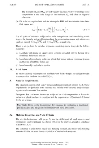
![16.1-201
Specification for Structural Steel Buildings, August 1, 2022
American Institute of Steel Construction
The plastic strength of the member cross section shall be represented in the analysis
either by an elastic-perfectly-plastic yield criterion expressed in terms of the axial
force, major-axis bending moment, and minor-axis bending moment, or by explicit
modeling of the material stress-strain response as elastic-perfectly-plastic.
3b. Geometric Imperfections
In all cases, the analysis shall directly model the effects of initial imperfections due
to both points of intersection of members displaced from their nominal locations
(system imperfections) and initial out-of-straightness or offsets of members along
their length (member imperfections). The magnitude of the initial displacements
shall be the maximum amount considered in the design; the pattern of initial dis-
placements shall be such that it provides the greatest destabilizing effect.
3c. Residual Stress and Partial Yielding Effects
The analysis shall include the influence of residual stresses and partial yielding. This
shall be done by explicitly modeling these effects in the analysis or by reducing the
stiffness of all structural components as specified in Section C2.3.
If the provisions of Section C2.3 are used, then
(a)
The 0.9 stiffness reduction factor specified in Section 1.3.3a shall be replaced
by the reduction of the modulus of elasticity, E, by 0.80 as specified in Section
C2.3, and
(b)
The elastic-perfectly-plastic yield criterion, expressed in terms of the axial force,
major-axis bending moment, and minor-axis bending moment, shall satisfy
the cross-section strength limit defined by Equations H1-1a and H1-1b using
Pc = 0.9Py, Mcx = 0.9Mpx, and Mcy = 0.9Mpy.
App. 1.3.] DESIGN BY INELASTIC ANALYSIS
Part 16.1 Appendix A1-A4 (195-266).indd 201
Part 16.1 Appendix A1-A4 (195-266).indd 201 2023-01-10 8:25 PM
2023-01-10 8:25 PM](https://image.slidesharecdn.com/aisc360-22specificationforstructuralsteelbuildings-231108145904-1b416cfe/85/AISC-360-22-Specification-for-Structural-Steel-Buildings-pdf-269-320.jpg)
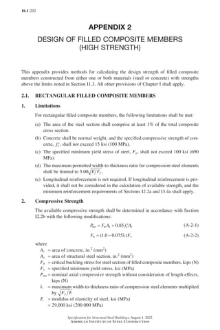
![16.1-203
Specification for Structural Steel Buildings, August 1, 2022
American Institute of Steel Construction
3. Flexural Strength
The available flexural strength shall be determined as follows:
φb = 0.90 (LRFD) Wb = 1.67 (ASD)
The nominal flexural strength, Mn, shall be determined as 90% of the moment cor-
responding to a stress distribution over the composite cross section assuming that
steel components have reached a stress of Fy in tension and Fn in compression, where
Fn is calculated using Equation A-2-2, and concrete components in compression
have reached a stress of 0 85
. ′
fc , where ′
fc is the specified compressive strength of
concrete, ksi (MPa).
4. Combined Flexure and Axial Force
The interaction of flexure and compression shall be limited by Equations I5-1a and
I5-1b, where the term cp is determined using Equation A-2-3 and cm is determined
using Equation A-2-4:
c
B H P P
f
F
p
n no
c
y
= − +
′
0 175
0 075 0 3
.
. .
λ (A-2-3)
c
P
P
B
H
F
F
f
F
m
n
no
y max
y
c
y
= +
+
′
0 6 0 3 0 6
2
. . .
,
λ
(A-2-4)
where
B = flange width of rectangular cross section, in. (mm)
H = web depth of rectangular cross section, in. (mm)
Fy,max = maximum permitted yield stress of steel = 100 ksi (690 MPa)
Pn =
nominal axial strength calculated in accordance with Section 2.1.2,
kips (N)
Pno =
nominal axial compressive strength without consideration of length ef-
fects calculated in accordance with Section 2.1.2, kips (N)
App. 2.1.] RECTANGULAR FILLED COMPOSITE MEMBERS
Part 16.1 Appendix A1-A4 (195-266).indd 203
Part 16.1 Appendix A1-A4 (195-266).indd 203 2023-01-10 8:25 PM
2023-01-10 8:25 PM](https://image.slidesharecdn.com/aisc360-22specificationforstructuralsteelbuildings-231108145904-1b416cfe/85/AISC-360-22-Specification-for-Structural-Steel-Buildings-pdf-271-320.jpg)
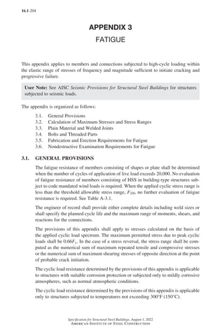
![16.1-205
Specification for Structural Steel Buildings, August 1, 2022
American Institute of Steel Construction
3.2. CALCULATION OF MAXIMUM STRESSES AND STRESS RANGES
Calculated stresses shall be based upon elastic analysis. Stresses shall not be ampli-
fied by stress concentration factors for geometrical discontinuities.
For bolts and threaded rods subjected to axial tension, the calculated stresses shall
include the effects of prying action, if any. In the case of axial stress combined with
bending, the maximum stresses of each kind shall be those determined for concurrent
arrangements of the applied load.
For members having symmetric cross sections, the fasteners and welds shall be
arranged symmetrically about the axis of the member, or the total stresses including
those due to eccentricity shall be included in the calculation of the stress range.
For axially loaded angle members where the center of gravity of the connecting
welds lies between the line of the center of gravity of the angle cross section and the
center of the connected leg, the effects of eccentricity shall be ignored. If the center
of gravity of the connecting welds lies outside this zone, the total stresses, including
those due to joint eccentricity, shall be included in the calculation of stress range.
3.3. PLAIN MATERIAL AND WELDED JOINTS
In plain material and welded joints, the range of stress due to the applied cyclic loads
shall not exceed the allowable stress range computed as follows.
(a)
For stress categories A, B, B′, C, D, E, and E′, the allowable stress range, FSR,
shall be determined by Equation A-3-1 or A-3-1M, as follows:
F
C
n
F
SR
f
SR
TH
=
≥
1 000
0 333
,
.
(A-3-1)
F
C
n
F
SR
f
SR
TH
=
≥
6 900
0 333
.
(A-3-1M)
where
Cf = constant from Table A-3.1 for the fatigue category
FSR = allowable stress range, ksi (MPa)
FTH = threshold allowable stress range, maximum stress range for indefinite de-
sign life from Table A-3.1, ksi (MPa)
nSR = number of stress range fluctuations in design life
(b)
For stress category F, the allowable stress range, FSR, shall be determined by
Equation A-3-2 or A-3-2M as follows:
F
n
SR
SR
=
≥
100
1 5
8
0 167
.
.
ksi (A-3-2)
F
n
SR
SR
=
≥
690
1 5
55
0 167
.
.
MPa (A-3-2M)
App. 3.3.] PLAIN MATERIAL AND WELDED JOINTS
Part 16.1 Appendix A1-A4 (195-266).indd 205
Part 16.1 Appendix A1-A4 (195-266).indd 205 2023-01-10 8:25 PM
2023-01-10 8:25 PM](https://image.slidesharecdn.com/aisc360-22specificationforstructuralsteelbuildings-231108145904-1b416cfe/85/AISC-360-22-Specification-for-Structural-Steel-Buildings-pdf-273-320.jpg)
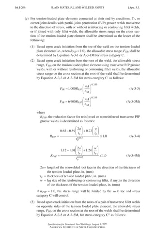
![16.1-207
Specification for Structural Steel Buildings, August 1, 2022
American Institute of Steel Construction
F R
n
SR FIL
SR
=
1 000
4 4
0 333
,
.
.
(A-3-5)
F R
n
SR FIL
SR
=
6 900
4 4
0 333
.
.
(A-3-5M)
where
RFIL =
reduction factor for joints using a pair of transverse fillet welds
only
=
+ ( ) ≤
0 06 0 72
1 0
0 167
. .
.
.
w t
t
p
p
(A-3-6)
=
+ ( ) ≤
0 103 1 24
1 0
0 167
. .
.
.
w t
t
p
p
(A-3-6M)
If RFIL = 1.0, the stress range will be limited by the weld toe and stress cate-
gory C will control.
User Note: Stress categories C′ and C′′ are cases where the fatigue crack initiates
in the root of the weld. These cases do not have a fatigue threshold and cannot
be designed for an infinite life. Infinite life can be approximated by use of a very
high cycle life such as 2 × 10⁸. Alternatively, if the size of the weld is increased
such that RFIL or RPJP is equal to 1.0, then the base metal controls, resulting in
stress category C, where there is a fatigue threshold and the crack initiates at the
toe of the weld.
3.4. BOLTS AND THREADED PARTS
In bolts and threaded parts, the range of stress of the applied cyclic load shall not
exceed the allowable stress range computed as follows.
(a)
For mechanically fastened connections loaded in shear, the maximum range of
stress in the connected material of the applied cyclic load shall not exceed the
allowable stress range computed using Equation A-3-1 or A-3-1M, where Cf and
FTH are taken from Section 2 of Table A-3.1.
(b)
For high-strength bolts, common bolts, threaded anchor rods, and hanger rods
with cut, ground, or rolled threads, the maximum range of tensile stress on the
net tensile area from applied axial load and moment plus load due to prying
action shall not exceed the allowable stress range computed using Equation
A-3-1 or A-3-1M, where Cf and FTH are taken from Case 8.5 (stress category G).
The net area in tension, At, is given by Equation A-3-7 or A-3-7M.
A d
n
t b
= −
π
4
0 9743
2
.
(A-3-7)
A d p
t b
= −
( )
π
4
0 9382
2
. (A-3-7M)
App. 3.4.] BOLTS AND THREADED PARTS
Part 16.1 Appendix A1-A4 (195-266).indd 207
Part 16.1 Appendix A1-A4 (195-266).indd 207 2023-01-29 12:16 PM
2023-01-29 12:16 PM](https://image.slidesharecdn.com/aisc360-22specificationforstructuralsteelbuildings-231108145904-1b416cfe/85/AISC-360-22-Specification-for-Structural-Steel-Buildings-pdf-275-320.jpg)
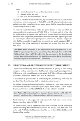
![16.1-209
Specification for Structural Steel Buildings, August 1, 2022
American Institute of Steel Construction
Fillet welds subjected to cyclic loading normal to the outstanding legs of angles, or
on the outer edges of end plates, shall have end returns around the corner for a dis-
tance not less than two times the weld size; the end return distance shall not exceed
four times the weld size.
3.6.
NONDESTRUCTIVE EXAMINATION REQUIREMENTS FOR
FATIGUE
In the case of CJP groove welds, the maximum allowable stress range calculated by
Equation A-3-1 or A-3-1M applies only to welds that have been radiographically or
ultrasonically tested and meet the acceptance requirements of Structural Welding
Code—Steel, AWS D1.1/D1.1M, clause 8.12.2 or clause 8.13.2.
App. 3.6.] NONDESTRUCTIVE EXAMINATION REQUIREMENTS FOR FATIGUE
Part 16.1 Appendix A1-A4 (195-266).indd 209
Part 16.1 Appendix A1-A4 (195-266).indd 209 2023-01-10 8:25 PM
2023-01-10 8:25 PM](https://image.slidesharecdn.com/aisc360-22specificationforstructuralsteelbuildings-231108145904-1b416cfe/85/AISC-360-22-Specification-for-Structural-Steel-Buildings-pdf-277-320.jpg)
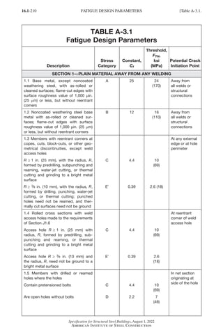
![16.1-211
Specification for Structural Steel Buildings, August 1, 2022
American Institute of Steel Construction
Table A-3.1.] FATIGUE DESIGN PARAMETERS
TABLE A-3.1 (continued)
Fatigue Design Parameters
Illustrative Typical Examples
SECTION 1—PLAIN MATERIAL AWAY FROM ANY WELDING
1.1 and 1.2
1.3
1.4
1.5
Part 16.1 Appendix A1-A4 (195-266).indd 211
Part 16.1 Appendix A1-A4 (195-266).indd 211 2023-01-29 12:18 PM
2023-01-29 12:18 PM](https://image.slidesharecdn.com/aisc360-22specificationforstructuralsteelbuildings-231108145904-1b416cfe/85/AISC-360-22-Specification-for-Structural-Steel-Buildings-pdf-279-320.jpg)
![16.1-212
Specification for Structural Steel Buildings, August 1, 2022
American Institute of Steel Construction
TABLE A-3.1 (continued)
Fatigue Design Parameters
Description
Stress
Category
Constant,
Cf
Threshold,
FTH,
ksi
(MPa)
Potential Crack
Initiation Point
SECTION 2—CONNECTED MATERIAL IN MECHANICALLY FASTENED JOINTS
2.1 Gross area of base metal in lap
joints connected by high-strength bolts
where the joints satisfy all require-
ments for slip-critical connections[a]
B 12 16
(110)
Through gross
section not
through the
hole
2.2 Net area of base metal in lap joints
connected by high-strength bolts
where the joints satisfy all require-
ments for pretensioned connections[b]
B 12 16
(110)
In net section
originating at
side of hole
2.3 Net section of base metal in exist-
ing riveted joints
D 2.2 7
(48)
In net section
originating at
side of hole
2.4 Net section in base metal of eyebar
or pin plate connections
E 1.1 4.5
(31)
In net section
originating at
side of hole
[a]
Slip-critical connections are required by the RCSC Specification for joints subject to the provisions of this
appendix with reversal of the loading direction [see RCSC Specification Section 4.3(1)], and permitted for
other loading conditions (see RCSC Specification Section 4.3 Commentary). Holes may be prepared by any
method permitted by this Specification.
[b]
Pretensioned connections are restricted by the RCSC Specification to cyclically loaded connections where
there is no reversal of loading direction [see RCSC Specification Section 4.2(3)]. Holes may be prepared by
any method permitted by this Specification but the RCSC Specification requires thermally cut holes to be
approved by the engineer of record (see RCSC Specification Section 3.3).
FATIGUE DESIGN PARAMETERS [Table A-3.1.
Part 16.1 Appendix A1-A4 (195-266).indd 212
Part 16.1 Appendix A1-A4 (195-266).indd 212 2023-01-10 8:25 PM
2023-01-10 8:25 PM](https://image.slidesharecdn.com/aisc360-22specificationforstructuralsteelbuildings-231108145904-1b416cfe/85/AISC-360-22-Specification-for-Structural-Steel-Buildings-pdf-280-320.jpg)
![16.1-213
Specification for Structural Steel Buildings, August 1, 2022
American Institute of Steel Construction
TABLE A-3.1 (continued)
Fatigue Design Parameters
Illustrative Typical Examples
SECTION 2—CONNECTED MATERIAL IN MECHANICALLY FASTENED JOINTS
2.1
2.2
2.3
2.4
Table A-3.1.] FATIGUE DESIGN PARAMETERS
Part 16.1 Appendix A1-A4 (195-266).indd 213
Part 16.1 Appendix A1-A4 (195-266).indd 213 2023-01-10 8:25 PM
2023-01-10 8:25 PM](https://image.slidesharecdn.com/aisc360-22specificationforstructuralsteelbuildings-231108145904-1b416cfe/85/AISC-360-22-Specification-for-Structural-Steel-Buildings-pdf-281-320.jpg)
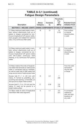
![16.1-215
Specification for Structural Steel Buildings, August 1, 2022
American Institute of Steel Construction
TABLE A-3.1 (continued)
Fatigue Design Parameters
Illustrative Typical Examples
SECTION 3—WELDED JOINTS JOINING COMPONENTS OF BUILT-UP MEMBERS
3.1
3.2
3.3
3.4
Table A-3.1.] FATIGUE DESIGN PARAMETERS
Part 16.1 Appendix A1-A4 (195-266).indd 215
Part 16.1 Appendix A1-A4 (195-266).indd 215 2023-01-10 8:25 PM
2023-01-10 8:25 PM](https://image.slidesharecdn.com/aisc360-22specificationforstructuralsteelbuildings-231108145904-1b416cfe/85/AISC-360-22-Specification-for-Structural-Steel-Buildings-pdf-283-320.jpg)
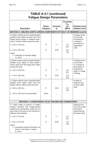
![16.1-217
Specification for Structural Steel Buildings, August 1, 2022
American Institute of Steel Construction
TABLE A-3.1 (continued)
Fatigue Design Parameters
Illustrative Typical Examples
SECTION 3—WELDED JOINTS JOINING COMPONENTS OF BUILT-UP MEMBERS (cont’d)
3.5
3.6
3.7
SECTION 4—LONGITUDINAL FILLET WELDED END CONNECTIONS
4.1
Table A-3.1.] FATIGUE DESIGN PARAMETERS
Part 16.1 Appendix A1-A4 (195-266).indd 217
Part 16.1 Appendix A1-A4 (195-266).indd 217 2023-01-10 8:25 PM
2023-01-10 8:25 PM](https://image.slidesharecdn.com/aisc360-22specificationforstructuralsteelbuildings-231108145904-1b416cfe/85/AISC-360-22-Specification-for-Structural-Steel-Buildings-pdf-285-320.jpg)
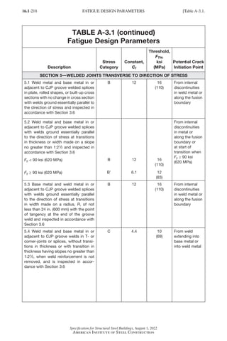
![16.1-219
Specification for Structural Steel Buildings, August 1, 2022
American Institute of Steel Construction
TABLE A-3.1 (continued)
Fatigue Design Parameters
Illustrative Typical Examples
SECTION 5—WELDED JOINTS TRANSVERSE TO DIRECTION OF STRESS
5.1
5.2
5.3
5.4
Table A-3.1.] FATIGUE DESIGN PARAMETERS
Part 16.1 Appendix A1-A4 (195-266).indd 219
Part 16.1 Appendix A1-A4 (195-266).indd 219 2023-01-10 8:25 PM
2023-01-10 8:25 PM](https://image.slidesharecdn.com/aisc360-22specificationforstructuralsteelbuildings-231108145904-1b416cfe/85/AISC-360-22-Specification-for-Structural-Steel-Buildings-pdf-287-320.jpg)
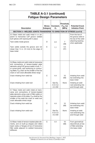
![16.1-221
Specification for Structural Steel Buildings, August 1, 2022
American Institute of Steel Construction
TABLE A-3.1 (continued)
Fatigue Design Parameters
Illustrative Typical Examples
SECTION 5—WELDED JOINTS TRANSVERSE TO DIRECTION OF STRESS (cont’d)
5.5
---
Category D
(a) (b)
(c)
5.6
(a) (b)
Site for potential crack
initiation due to bending
tensile stress
(c)
5.7
(a) (b) (c)
Root Crack
Category C
(d) (e)
5.8
Table A-3.1.] FATIGUE DESIGN PARAMETERS
Part 16.1 Appendix A1-A4 (195-266).indd 221
Part 16.1 Appendix A1-A4 (195-266).indd 221 2023-01-10 8:25 PM
2023-01-10 8:25 PM](https://image.slidesharecdn.com/aisc360-22specificationforstructuralsteelbuildings-231108145904-1b416cfe/85/AISC-360-22-Specification-for-Structural-Steel-Buildings-pdf-289-320.jpg)
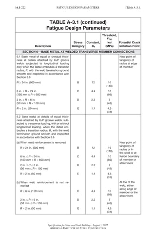
![16.1-223
Specification for Structural Steel Buildings, August 1, 2022
American Institute of Steel Construction
TABLE A-3.1 (continued)
Fatigue Design Parameters
Illustrative Typical Examples
SECTION 6—BASE METAL AT WELDED TRANSVERSE MEMBER CONNECTIONS
6.1
6.2
Table A-3.1.] FATIGUE DESIGN PARAMETERS
Part 16.1 Appendix A1-A4 (195-266).indd 223
Part 16.1 Appendix A1-A4 (195-266).indd 223 2023-01-10 8:25 PM
2023-01-10 8:25 PM](https://image.slidesharecdn.com/aisc360-22specificationforstructuralsteelbuildings-231108145904-1b416cfe/85/AISC-360-22-Specification-for-Structural-Steel-Buildings-pdf-291-320.jpg)
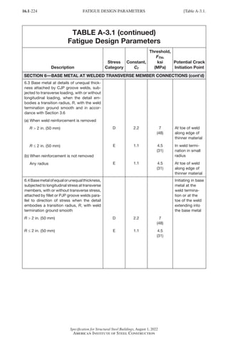
![16.1-225
Specification for Structural Steel Buildings, August 1, 2022
American Institute of Steel Construction
TABLE A-3.1 (continued)
Fatigue Design Parameters
Illustrative Typical Examples
SECTION 6—BASE METAL AT WELDED TRANSVERSE MEMBER CONNECTIONS (cont’d)
6.3
6.4
Table A-3.1.] FATIGUE DESIGN PARAMETERS
Part 16.1 Appendix A1-A4 (195-266).indd 225
Part 16.1 Appendix A1-A4 (195-266).indd 225 2023-01-10 8:25 PM
2023-01-10 8:25 PM](https://image.slidesharecdn.com/aisc360-22specificationforstructuralsteelbuildings-231108145904-1b416cfe/85/AISC-360-22-Specification-for-Structural-Steel-Buildings-pdf-293-320.jpg)
![16.1-226
Specification for Structural Steel Buildings, August 1, 2022
American Institute of Steel Construction
TABLE A-3.1 (continued)
Fatigue Design Parameters
Description
Stress
Category
Constant,
Cf
Threshold,
FTH,
ksi
(MPa)
Potential Crack
Initiation Point
SECTION 7—BASE METAL AT SHORT ATTACHMENTS[a]
7.1 Base metal subjected to longitudinal
loading at details with welds parallel or
transverse to the direction of stress, with or
without transverse load on the detail, where
the detail embodies no transition radius,
R, and with detail length, a, in direction of
stress and thickness of the attachment, b
a 2 in. (50 mm) for any thickness, b
2 in. (50 mm) ≤ a ≤ 4 in. (100 mm) and
a ≤ 12b
2 in. (50 mm) ≤ a ≤ 4 in. (100 mm) and
a 12b
a 4 in. (100 mm) and b ≤ 0.8 in. (20 mm)
a 4 in. (100 mm)
and b 0.8 in. (20 mm)
C
D
E
E′
4.4
2.2
1.1
0.39
10
(69)
7
(48)
4.5
(31)
2.6
(18)
Initiating in base
metal at the
weld termina-
tion or at the
toe of the weld
extending into
the base metal
7.2 Base metal subjected to longitudinal
stress at details attached by fillet or PJP
groove welds, with or without transverse
load on detail, when the detail embodies a
transition radius, R, with weld termination
ground smooth
R 2 in. (50 mm)
R ≤ 2 in. (50 mm)
D
E
2.2
1.1
7
(48)
4.5
(31)
Initiating in base
metal at the
weld termina-
tion, extending
into the base
metal
[a]
“Attachment,” as used herein, is defined as any steel detail welded to a member that causes a deviation in
the stress flow in the member and, thus, reduces the fatigue resistance. The reduction is due to the pres-
ence of the attachment, not due to the loading on the attachment.
FATIGUE DESIGN PARAMETERS [Table A-3.1.
Part 16.1 Appendix A1-A4 (195-266).indd 226
Part 16.1 Appendix A1-A4 (195-266).indd 226 2023-01-10 8:25 PM
2023-01-10 8:25 PM](https://image.slidesharecdn.com/aisc360-22specificationforstructuralsteelbuildings-231108145904-1b416cfe/85/AISC-360-22-Specification-for-Structural-Steel-Buildings-pdf-294-320.jpg)
![16.1-227
Specification for Structural Steel Buildings, August 1, 2022
American Institute of Steel Construction
TABLE A-3.1 (continued)
Fatigue Design Parameters
Illustrative Typical Examples
SECTION 7—BASE METAL AT SHORT ATTACHMENTS[a]
7.1
7.2
[a]
“Attachment,” as used herein, is defined as any steel detail welded to a member that causes a deviation in
the stress flow in the member and, thus, reduces the fatigue resistance. The reduction is due to the pres-
ence of the attachment, not due to the loading on the attachment.
Table A-3.1.] FATIGUE DESIGN PARAMETERS
Part 16.1 Appendix A1-A4 (195-266).indd 227
Part 16.1 Appendix A1-A4 (195-266).indd 227 2023-01-10 8:25 PM
2023-01-10 8:25 PM](https://image.slidesharecdn.com/aisc360-22specificationforstructuralsteelbuildings-231108145904-1b416cfe/85/AISC-360-22-Specification-for-Structural-Steel-Buildings-pdf-295-320.jpg)
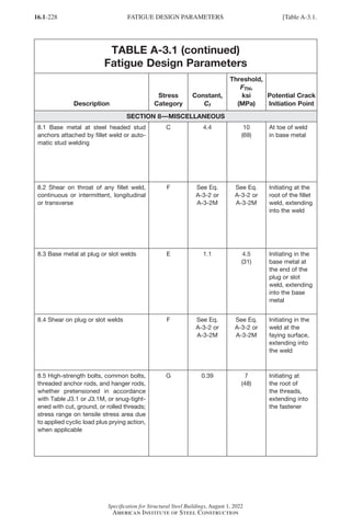
![16.1-229
Specification for Structural Steel Buildings, August 1, 2022
American Institute of Steel Construction
TABLE A-3.1 (continued)
Fatigue Design Parameters
Illustrative Typical Examples
SECTION 8—MISCELLANEOUS
8.1
8.2
8.3
8.4
8.5
Table A-3.1.] FATIGUE DESIGN PARAMETERS
Part 16.1 Appendix A1-A4 (195-266).indd 229
Part 16.1 Appendix A1-A4 (195-266).indd 229 2023-01-10 8:25 PM
2023-01-10 8:25 PM](https://image.slidesharecdn.com/aisc360-22specificationforstructuralsteelbuildings-231108145904-1b416cfe/85/AISC-360-22-Specification-for-Structural-Steel-Buildings-pdf-297-320.jpg)
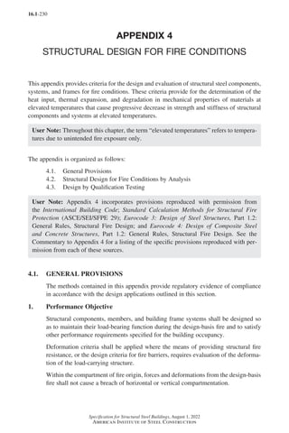
![16.1-231
Specification for Structural Steel Buildings, August 1, 2022
American Institute of Steel Construction
2. Design by Engineering Analysis
The analysis methods in Section 4.2 are permitted to be used to document the antici-
pated performance of steel framing when subjected to design-basis fire scenarios.
Methods in Section 4.2 provide evidence of compliance with performance objectives
established in Section 4.1.1.
The analysis methods in Section 4.2 are permitted to be used to demonstrate an
equivalency for an alternative material or method, as permitted by the applicable
building code (ABC).
Structural design for fire conditions using Appendix 4.2 shall be performed using
the load and resistance factor design (LRFD) method in accordance with the provi-
sions of Section B3.1, unless a design based on advanced analysis is performed in
accordance with Section 4.2.4c. Ambient resistance factors shall be used with the
LRFD method.
3. Design by Qualification Testing
The qualification testing methods in Section 4.3 are permitted to be used to document
the fire resistance of steel framing subject to the standardized fire testing protocols
required by the ABC.
4. Load Combinations and Required Strength
In the absence of ABC provisions for design under fire exposures, the required
strength of the structure and its elements shall be determined from the gravity load
combination as follows:
(0.9 or 1.2)D + AT + 0.5L + 0.2S (A-4-1)
where
AT =
nominal forces and deformations due to the design-basis fire defined in
Section 4.2.1
D = nominal dead load
L = nominal occupancy live load
S = nominal snow load
User Note: ASCE/SEI 7, Section 2.5, contains Equation A-4-1 for extraordinary
events, which includes fire. Live load reduction is usually considered in accor-
dance with ASCE/SEI 7.
4.2. STRUCTURAL DESIGN FOR FIRE CONDITIONS BY ANALYSIS
It is permitted to design structural members, components, and building frames for
elevated temperatures in accordance with the requirements of this section.
1. Design-Basis Fire
A design-basis fire shall be identified to describe the heating and cooling conditions
for the structure. These heating and cooling conditions shall relate to the fuel com-
modities and compartment characteristics present in the assumed fire area. The fuel
App. 4.2.] STRUCTURAL DESIGN FOR FIRE CONDITIONS BY ANALYSIS
Part 16.1 Appendix A1-A4 (195-266).indd 231
Part 16.1 Appendix A1-A4 (195-266).indd 231 2023-01-10 8:25 PM
2023-01-10 8:25 PM](https://image.slidesharecdn.com/aisc360-22specificationforstructuralsteelbuildings-231108145904-1b416cfe/85/AISC-360-22-Specification-for-Structural-Steel-Buildings-pdf-299-320.jpg)
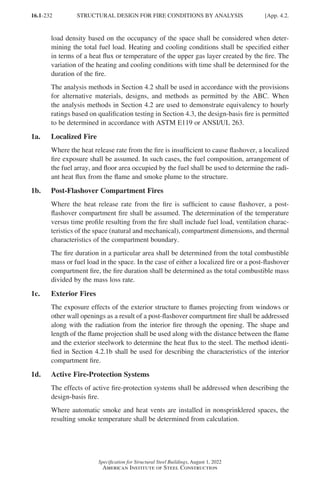
![16.1-233
Specification for Structural Steel Buildings, August 1, 2022
American Institute of Steel Construction
2. Temperatures in Structural Systems Under Fire Conditions
Temperatures within structural members, components, and frames due to the heat-
ing conditions posed by the design-basis fire shall be determined by a heat transfer
analysis.
3. Material Properties at Elevated Temperatures
The effects of elevated temperatures on the physical and mechanical properties of
materials shall be considered in the analysis and design of structural members, com-
ponents, and systems. Any rational method that establishes material properties at
elevated temperatures that is based on test data is permitted, including the methods
defined in Sections 4.2.3a and 4.2.3b.
3a. Thermal Elongation
The coefficients of thermal expansion shall be taken to be as follows.
(a) For structural and reinforcing steels: For calculations at temperatures above 150°F
(66°C), the coefficient of thermal expansion is 7.8 × 10⁻⁶/°F (1.4 × 10⁻⁵/°C).
(b)
For normal weight concrete: For calculations at temperatures above 150°F
(66°C), the coefficient of thermal expansion is 10 × 10-6/°F (1.8 ×10⁻⁵/°C).
(c)
For lightweight concrete: For calculations at temperatures above 150°F (66°C),
the coefficient of thermal expansion is 4.4 × 10⁻⁶/°F (7.9 × 10⁻⁶/°C).
3b.
Mechanical Properties of Structural Steel, Hot-Rolled Reinforcing Steel,
and Concrete at Elevated Temperatures
The uniaxial engineering stress-strain-temperature relationship for structural steel,
hot-rolled reinforcing steel, and concrete shall be determined using this section.
This applies only to structural and reinforcing steels with a specified minimum yield
strength, Fy, equal to 65 ksi (450 MPa) or less, and to concrete with a specified com-
pressive strength, ′
fc , equal to 8 ksi (55 MPa) or less.
(a) Structural and hot-rolled reinforcing steel
Table A-4.2.1 provides retention factors, kE, kp, and ky, for steel which are
expressed as the ratio of the mechanical property at elevated temperature with
respect to the property at ambient, assumed to be 68°F (20°C). It is permitted to
interpolate between these values. The properties at elevated temperature, T, are
defined as follows:
E T
( ) is the modulus of elasticity of steel at elevated temperature, ksi (MPa),
which is calculated as the retention factor, kE, times the ambient property as
specified in Table A-4.2.1.
G T
( ) is the shear modulus of elasticity of steel at elevated temperature, ksi
(MPa), which is calculated as the retention factor, kE, times the ambient property
as specified in Table A-4.2.1.
Fy T
( ) is the specified minimum yield stress of steel at elevated temperature, ksi
(MPa), which is calculated as the retention factor, ky, times the ambient property
as specified in Table A-4.2.1.
App. 4.2.] STRUCTURAL DESIGN FOR FIRE CONDITIONS BY ANALYSIS
Part 16.1 Appendix A1-A4 (195-266).indd 233
Part 16.1 Appendix A1-A4 (195-266).indd 233 2023-01-10 8:25 PM
2023-01-10 8:25 PM](https://image.slidesharecdn.com/aisc360-22specificationforstructuralsteelbuildings-231108145904-1b416cfe/85/AISC-360-22-Specification-for-Structural-Steel-Buildings-pdf-301-320.jpg)
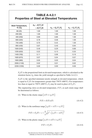
![16.1-235
Specification for Structural Steel Buildings, August 1, 2022
American Institute of Steel Construction
where
e T
( ) = engineering strain at elevated temperature, in./in. (mm/mm)
ep T
( ) =
engineering strain at the proportional limit at elevated temperature,
in./in. (mm/mm)
= T
p( )
F T
( )
E
eu T
( ) = ultimate strain at elevated temperature
= 0.15 in./in. (mm/mm)
ey T
( ) = engineering yield strain at elevated temperature
= 0.02 in./in. (mm/mm)
a2 =
c
E T
( )
T
y ( )
ε T
− ( )
εp +
T
y( ) −
ε T
( )
εp (A-4-5)
b2 =
= ( ) ( ) − ( ) +
E T T T c c
y p
ε ε 2
(A-4-6)
c =
2
T
y( ) −
F T
( )
Fp
T T
p
( ) − ( )
ε ε
y T T
p
( ) − ( )
F F
y
− 2
T
( )
E
(A-4-7)
User Note: The equation for the plastic range conservatively neglects the
strain-hardening portion, but strain-hardening may be included. The plateau
of the plastic range does not exceed the ultimate strain, eu T
( ).
User Note: This section applies to structural steel materials specified in
Section A3.1 and to hot-rolled reinforcing steel with a specified minimum
yield strength, Fy, equal to 65 ksi (450 MPa) or less. This includes ASTM
A615/A615M Grade 60 (420) and ASTM A706/A706M Grade 60 (420) steel
reinforcement.
(b) Concrete
Table A-4.2.2 provides retention factors, kc and kEc, for concrete which are
expressed as the ratio of the mechanical property at elevated temperature with
respect to the property at ambient, assumed to be 68°F (20°C). It is permitted to
interpolate between these values. For lightweight concrete, values of ecu T
( ) shall
be obtained from tests. The properties at elevated temperature, T, are defined as
follows:
Ec T
( ) =
modulus of elasticity of concrete at elevated temperature, ksi (MPa),
which is calculated as the retention factor, kEc, times the ambient prop-
erty as specified in Table A-4.2.2
′
f T
c ( ) =
specified compressive strength of concrete at elevated temperature, ksi
(MPa), which is calculated as the retention factor, kc, times the ambient
property as specified in Table A-4.2.2
ecu T
( ) =
concrete strain corresponding to ′
f T
c ( ) at elevated temperature, in./in.
(mm/mm), which is specified in Table A-4.2.2
App. 4.2.] STRUCTURAL DESIGN FOR FIRE CONDITIONS BY ANALYSIS
Part 16.1 Appendix A1-A4 (195-266).indd 235
Part 16.1 Appendix A1-A4 (195-266).indd 235 2023-01-10 8:25 PM
2023-01-10 8:25 PM](https://image.slidesharecdn.com/aisc360-22specificationforstructuralsteelbuildings-231108145904-1b416cfe/85/AISC-360-22-Specification-for-Structural-Steel-Buildings-pdf-303-320.jpg)
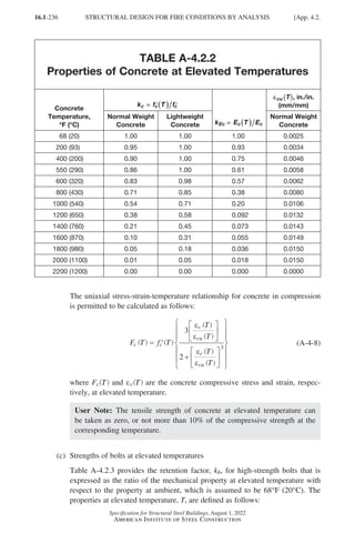
![16.1-237
Specification for Structural Steel Buildings, August 1, 2022
American Institute of Steel Construction
TABLE A-4.2.3
Properties of Group 120 and Group 150
High-Strength Bolts at Elevated Temperatures
Bolt Temperature,
°
°F (°
°C)
k F T F
F T F
b nt nt
nv nv
=
=
=
=
=
=
(
( )
)
(
( )
)
68 (20) 1.00
200 (93) 0.97
300 (150) 0.95
400 (200) 0.93
600 (320) 0.88
800 (430) 0.71
900 (480) 0.59
1000 (540) 0.42
1200 (650) 0.16
1400 (760) 0.08
1600 (870) 0.04
1800 (980) 0.01
2000 (1100) 0.00
Fnt T
( ) =
nominal tensile strength of the bolt, ksi (MPa), which is calculated as
the retention factor, kb, times the ambient property as specified in Table
A-4.2.3
Fnv T
( ) =
nominal shear strength of the bolt, ksi (MPa), which is calculated as
the retention factor, kb, times the ambient property as specified in Table
A-4.2.3
4. Structural Design Requirements
4a. General Requirements
The structural frame and foundation shall be capable of providing the strength and
deformation capacity to withstand, as a system, the structural actions developed dur-
ing the fire within the prescribed limits of deformation. The structural system shall
be designed to sustain local damage with the structural system as a whole remaining
stable. Frame stability and required strength shall be determined in accordance with
the requirements of Section C1.
Continuous load paths shall be provided to transfer all forces from the exposed
region to the final point of resistance.
The size and spacing of vent holes in filled composite members shall be evaluated
such that no applicable strength limit states in the steel elements are exceeded due
App. 4.2.] STRUCTURAL DESIGN FOR FIRE CONDITIONS BY ANALYSIS
Part 16.1 Appendix A1-A4 (195-266).indd 237
Part 16.1 Appendix A1-A4 (195-266).indd 237 2023-01-10 8:25 PM
2023-01-10 8:25 PM](https://image.slidesharecdn.com/aisc360-22specificationforstructuralsteelbuildings-231108145904-1b416cfe/85/AISC-360-22-Specification-for-Structural-Steel-Buildings-pdf-305-320.jpg)
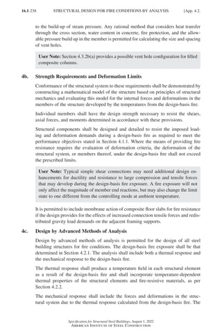
![16.1-239
Specification for Structural Steel Buildings, August 1, 2022
American Institute of Steel Construction
mechanical response shall take into account explicitly the deterioration in strength
and stiffness with increasing temperature, the effects of thermal expansions, inelastic
behavior and load redistribution, large deformations, time-dependent effects such as
creep, and uncertainties resulting from variability in material properties at elevated
temperature. Support and restraint conditions (forces, moments, and boundary condi-
tions) shall represent the behavior of the structure during a design-basis fire. Material
properties shall be defined as per Section 4.2.3.
The resulting analysis shall address all relevant limit states, such as excessive deflec-
tions, connection ruptures, and global and local buckling, and shall demonstrate an
adequate level of safety as required by the authority having jurisdiction.
4d. Design by Simple Methods of Analysis
The methods of analysis in this section are permitted to be used for the evaluation of
the performance of structural components and frames at elevated temperatures dur-
ing exposure to a design-basis fire.
When evaluating structural components, the stiffnesses and boundary conditions
applicable at ambient temperatures are permitted to be assumed to remain unchanged
throughout the fire exposure for the calculation of required strengths.
For evaluating the performance of structural frames during exposure to a design-basis
fire, the required strengths are also permitted to be determined through considera-
tion of reduced stiffness at elevated temperatures, boundary conditions, and thermal
deformations.
User Note: Determining the required strength assuming ambient temperatures
throughout the fire exposure is generally applicable to members in regular gravity
frames. Determining the required strength accounting for elevated temperatures
may be more appropriate for irregular structural frames.
The design strength shall be determined as in Section B3.1. The nominal strength,
Rn, shall be calculated using material properties, as provided in Section 4.2.3b, at the
temperature developed by the design-basis fire and as stipulated in Sections 4.2.4d(a)
through (h).
The simple method is only applicable to members with nonslender and/or compact
sections.
It is permitted to model the thermal response of steel and composite members using a
lumped heat capacity analysis with heat input as determined by the design-basis fire
defined in Section 4.2.1, using the temperature equal to the maximum steel tempera-
ture. For composite beams, the maximum steel temperature shall be assigned to the
bottom flange and a temperature gradient shall be applied to incorporate thermally
induced moments as stipulated in Section 4.2.4d(f).
For steel temperatures less than or equal to 400°F (200°C), the member and con-
nection design strengths are permitted to be determined without consideration of
temperature effects on the nominal strengths.
App. 4.2.] STRUCTURAL DESIGN FOR FIRE CONDITIONS BY ANALYSIS
Part 16.1 Appendix A1-A4 (195-266).indd 239
Part 16.1 Appendix A1-A4 (195-266).indd 239 2023-01-10 8:25 PM
2023-01-10 8:25 PM](https://image.slidesharecdn.com/aisc360-22specificationforstructuralsteelbuildings-231108145904-1b416cfe/85/AISC-360-22-Specification-for-Structural-Steel-Buildings-pdf-307-320.jpg)
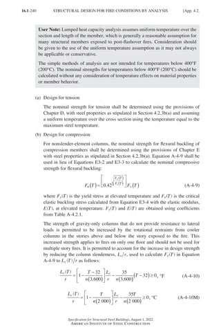
![16.1-241
Specification for Structural Steel Buildings, August 1, 2022
American Institute of Steel Construction
where
Lc = effective length of member, in. (mm)
=
KL
K = 1.0 for gravity-only columns
L = laterally unbraced length of the member, in. (mm)
T = temperature of structural steel, °F (°C)
n = 1 for columns with cooler columns both above and below
n = 2 for columns with cooler columns either above or below only
r = radius of gyration, in. (mm)
User Note: The design equations for compression predict flexural buckling
capacities of wide-flange rolled shapes, but do not consider local buckling
and torsional buckling. If applicable, these additional limit states must be
considered with an alternative method. For most fire conditions, uniform
heating and temperatures govern the design for compression. When uniform
heating is not a reasonable assumption, alternative methods must be used to
account for the effects of nonuniform heating and resulting thermal gradi-
ents on the design strength of compression members, as the simple method
assumes a uniform temperature distribution.
(c) Design for compression in filled composite columns
For filled composite columns, the nominal strength for compression shall be
determined using the provisions of Section I2.2 with steel and concrete proper-
ties as stipulated in Section 4.2.3b. Equation A-4-11 shall be used in lieu of
Equations I2-2 and I2-3 to calculate the nominal compressive strength for flex-
ural buckling:
P T P T
n
P T
P T
no
no
e
( ) =
( )
( )
( )
0 54
0 3
.
.
(A-4-11)
where Pno T
( ) is calculated at elevated temperature using Equations I2-9, I2-10,
and I2-11. Pe T
( ) is calculated at elevated temperature using Equation I2-4.
EIeff T
( ) is calculated at elevated temperature using Equations I2-12 and I2-13.
Fy T
( ), ′
f T
c ( ), Es T
( ), and Ec T
( ) are obtained using coefficients from Tables
A-4.2.1 and A-4.2.2.
(d) Design for compression in filled composite plate shear walls
For filled composite plate shear walls, the nominal strength for compression
shall be determined using the provisions of Section I2.3 with steel and concrete
properties as stipulated in Section 4.2.3b and Equation A-4-12 used in lieu of
Equations I2-2 and I2-3 to calculate the nominal compressive strength for flex-
ural buckling:
P T P T
n
P T
P T
no
no
e
( ) =
( )
( )
( )
0 32
0 3
.
.
(A-4-12)
App. 4.2.] STRUCTURAL DESIGN FOR FIRE CONDITIONS BY ANALYSIS
Part 16.1 Appendix A1-A4 (195-266).indd 241
Part 16.1 Appendix A1-A4 (195-266).indd 241 2023-09-24 10:51 PM
2023-09-24 10:51 PM](https://image.slidesharecdn.com/aisc360-22specificationforstructuralsteelbuildings-231108145904-1b416cfe/85/AISC-360-22-Specification-for-Structural-Steel-Buildings-pdf-309-320.jpg)
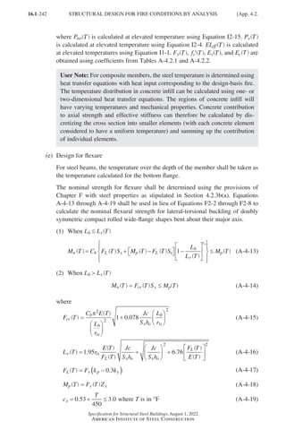
![16.1-243
Specification for Structural Steel Buildings, August 1, 2022
American Institute of Steel Construction
c
T
x = + ≤
0 6
250
3 0
. . where T is in °C (A-4-19M)
and
T = elevated temperature of steel due to unintended fire exposure, °F (°C)
The material properties at elevated temperatures, E T
( ) and Fy T
( ), and the reten-
tion factors, kp and ky, are calculated in accordance with Table A-4.2.1, and other
terms are as defined in Chapter F.
User Note: FL T
( ) represents the initial yield stress, which assumes a residual
stress of 0.3Fy. Alternatively, 10 ksi (69 MPa) may be used in place of 0.3Fy
for calculation of FL T
( ).
User Note: The equations for lateral-torsional buckling do not consider local
buckling. If applicable, the effects of local buckling must be considered with
an alternative method.
(f) Design for flexure in composite beams
For composite beams, the calculated bottom flange temperature shall be taken as
constant between the bottom flange and mid-depth of the web and shall decrease
linearly by no more than 25% from the mid-depth of the web to the top flange
of the beam.
The nominal strength of a composite flexural member shall be determined using
the provisions of Chapter I, with reduced yield stresses in the steel as determined
from Table A-4.2.1. Steel properties will vary as the temperature along the depth
of section changes.
Alternatively, the nominal flexural strength of a composite beam, Mn T
( ), is
permitted to be calculated using the bottom flange temperature, T, as follows:
M T k M
n cb n
=
( ) (A-4-20)
where
Mn =
nominal flexural strength at ambient temperature calculated in accor-
dance with provisions of Chapter I, kip-in. (N-mm)
kcb =
retention factor depending on bottom flange temperature, T, as given in
Table A-4.2.4
(g) Design for shear
The nominal strength for shear yielding shall be determined in accordance
with the provisions of Chapter G, with steel properties as stipulated in Section
4.2.3b(a) and assuming a uniform temperature over the cross section.
User Note: Shear yielding equations do not consider shear buckling or ten-
sion field action. If applicable, these limit states must be considered with an
alternative method.
App. 4.2.] STRUCTURAL DESIGN FOR FIRE CONDITIONS BY ANALYSIS
Part 16.1 Appendix A1-A4 (195-266).indd 243
Part 16.1 Appendix A1-A4 (195-266).indd 243 2023-01-10 8:25 PM
2023-01-10 8:25 PM](https://image.slidesharecdn.com/aisc360-22specificationforstructuralsteelbuildings-231108145904-1b416cfe/85/AISC-360-22-Specification-for-Structural-Steel-Buildings-pdf-311-320.jpg)
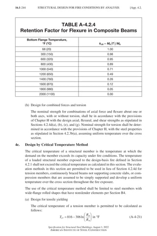
![16.1-245
Specification for Structural Steel Buildings, August 1, 2022
American Institute of Steel Construction
T
R
R
cr
u
n
= −
435 170ln in °C (A-4-21M)
where
Rn =
nominal yielding strength at ambient temperature determined in accor-
dance with Section D2, kips (N)
Ru =
equired tensile strength at elevated temperature, determined using the
load combination in Equation A-4-1 and greater than 0.01Rn, kips (N)
Tcr = critical temperature in °F (°C)
User Note: Tensile rupture in the net section is not considered in this critical
temperature calculation. It can be considered using an alternative method.
(b) Design for compression
The critical temperature of a compression member for flexural buckling is per-
mitted to be calculated as follows:
T
L
r
P
P
cr
c u
n
= −
−
1580 0 814 1300
. in °F (A-4-22)
T
L
r
P
P
cr
c u
n
= −
−
858 0 455 722
. in °C (A-4-22M)
where
Pn =
nominal compressive strength at ambient temperature determined in
accordance with the provisions in Section E3, kips (N)
Pu =
required compressive strength at elevated temperature, determined using
the load combination in Equation A-4-1, kips (N)
(c) Design for flexural yielding
The critical temperature of a continuously braced beam not supporting a con-
crete slab is permitted to be calculated as follows:
T
M
M
cr
u
n
= −
816 306ln in °F (A-4-23)
T
M
M
cr
u
n
= −
435 170ln in °C (A-4-23M)
where
Mn =
nominal flexural strength due to yielding at ambient temperature
determined in accordance with the provisions in Section F2.1, kip-in.
(N-mm)
Mu =
required flexural strength at elevated temperature, determined using the
load combination in Equation A-4-1 and greater than 0.01Mn, kip-in.
(N-mm)
Tcr = critical temperature in °F (°C)
App. 4.2.] STRUCTURAL DESIGN FOR FIRE CONDITIONS BY ANALYSIS
Part 16.1 Appendix A1-A4 (195-266).indd 245
Part 16.1 Appendix A1-A4 (195-266).indd 245 2023-01-10 8:25 PM
2023-01-10 8:25 PM](https://image.slidesharecdn.com/aisc360-22specificationforstructuralsteelbuildings-231108145904-1b416cfe/85/AISC-360-22-Specification-for-Structural-Steel-Buildings-pdf-313-320.jpg)
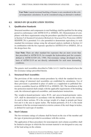
![16.1-247
Specification for Structural Steel Buildings, August 1, 2022
American Institute of Steel Construction
TABLE A-4.3.1
Minimum Fire Protection and Fire-Resistance
Ratings of Steel Assemblies[e]
Assembly
Item
Number Fire-Protection Material Used
Minimum Thickness of
Insulating Material for Fire-
Resistance Times, in. (mm)
4 hrs 3 hrs 2 hrs 1 hr
1.
Steel columns
and all of
primary
trusses
1-1.1 Carbonate, lightweight, and sand-light-
weight aggregate concrete, members
6 in. × 6 in. (150 mm × 150 mm) or greater
(not including sandstone, granite, and
siliceous gravel)[a]
21
/2
(63)
2
(50)
11
/2
(38)
1
(25)
1-1.2 Carbonate, lightweight, and sand-light-
weight aggregate concrete, members
8 in. × 8 in. (200 mm × 200 mm) or greater
(not including sandstone, granite, and
siliceous gravel)[a]
2
(50)
11
/2
(38)
1
(25)
1
(25)
1-1.3 Carbonate, lightweight, and sand-light-
weight aggregate concrete, members
12 in. × 12 in. (300 mm × 300 mm) or
greater (not including sandstone, granite,
and siliceous gravel)[a]
11
/2
(38)
1
(25)
1
(25)
1
(25)
1-1.4 Siliceous aggregate concrete and
concrete excluded in Item 1-1.1,
members 6 in. × 6 in. (150 mm × 150 mm)
or greater[a]
3
(75)
2
(50)
11
/2
(38)
1
(25)
1-1.5 Siliceous aggregate concrete and
concrete excluded in Item 1-1.1,
members 8 in. × 8 in. (200 mm × 200 mm)
or greater[a]
21
/2
(63)
2
(50)
1
(25)
1
(25)
1-1.6 Siliceous aggregate concrete and
concrete excluded in Item 1-1.1, members
12 in. × 12 in. (300 mm × 300 mm) or
greater[a]
2
(50)
1
(25)
1
(25)
1
(25)
1-2.1 Clay or shale brick with brick and mortar
fill[a]
33
/4
(94)
– –
21
/4
(56)
1-4.1 Cement plaster over metal lath wire tied
to 3
/4 in. (19 mm) cold-rolled vertical
channels with 0.049 in. (1.2 mm) (No. 18
B.W. Gage) wire ties spaced 3 to 6 in.
(75 to 150 mm) on center; plaster mixed
1:2.5 by volume, cement to sand
– –
21
/2
[b]
(63)[b]
7
/8
(22)
B.W. = Birmingham Wire
[a]Reentrant parts of protected members to be filled solidly.
[b]Two layers of equal thickness with a 3
/4 in. (19 mm) airspace between.
[e]
Generic fire-resistance ratings (those not designated as PROPRIETARY* in the listing) in GA-600 shall be
accepted as if herein listed.
Table A-4.3.1.] MINIMUM FIRE PROTECTION AND FIRE-RESISTANCE RATINGS
Part 16.1 Appendix A1-A4 (195-266).indd 247
Part 16.1 Appendix A1-A4 (195-266).indd 247 2023-01-10 8:25 PM
2023-01-10 8:25 PM](https://image.slidesharecdn.com/aisc360-22specificationforstructuralsteelbuildings-231108145904-1b416cfe/85/AISC-360-22-Specification-for-Structural-Steel-Buildings-pdf-315-320.jpg)
![16.1-248
Specification for Structural Steel Buildings, August 1, 2022
American Institute of Steel Construction
TABLE A-4.3.1 (continued)
Minimum Fire Protection and Fire-Resistance
Ratings of Steel Assemblies[e]
Assembly
Item
Number Fire-Protection Material Used
Minimum Thickness of
Insulating Material for Fire-
Resistance Times, in. (mm)
4 hrs 3 hrs 2 hrs 1 hr
1.
Steel columns
and all of
primary
trusses
1-5.1 Vermiculite concrete, 1:4 mix by volume
over paperbacked wire fabric lath wrapped
directly around column with additional
2 × 2 in. 0.065 / 0.065 in. (No. 16/16 B.W.
Gage) (50 × 50 mm 1.7 / 1.7 mm) wire
fabric placed 3
/4 in. (19 mm) from outer
concrete surface; wire fabric tied with
0.049 in. (1.2 mm) (No. 18 B.W. Gage) wire
spaced 6 in. (150 mm) on center for inner
layer and 2 in. (50 mm) on center for outer
layer
2
(50)
– – –
1-6.1 Perlite or vermiculite gypsum plaster
over metal lath wrapped around column
and furred 11
/4 in. (31 mm) from column
flanges; sheets lapped at ends and tied
at 6 in. (150 mm) intervals with 0.049 in.
(1.2 mm) (No. 18 B.W. Gage) tie wire;
plaster pushed through to flanges
11
/2
(38)
1
(25)
– –
1-6.2 Perlite or vermiculite gypsum plaster over
self-furring metal lath wrapped directly
around column, lapped 1 in. (25 mm)
and tied at 6 in. (150 mm) intervals with
0.049 in. (1.2 mm) (No. 18 B.W. Gage)
wire
13
/4
(44)
13
/8
(35)
1
(25)
–
1-6.3 Perlite or vermiculite gypsum plaster
on metal lath applied to 3
/4 in. (19 mm)
cold-rolled channels spaced 24 in.
(600 mm) apart vertically and wrapped
flatwise around column
11
/2
(38)
– – –
1-6.4 Perlite or vermiculite gypsum plaster
over two layers of 1
/2 in. (13 mm) plain
full-length gypsum lath applied tight to
column flanges; lath wrapped with 1 in.
(25 mm) hexagonal mesh of 0.035 in.
(0.89 mm) (No. 20 Gage) wire and tied
with doubled 0.049-in.- (1.2-mm-)
diameter (No. 18 B.W. Gage) wire ties
spaced 23 in. (580 mm) on center; for
three-coat work, the plaster mix for the
second coat shall not exceed 100 pounds
(45 kg) of gypsum to 2.5 ft3 (0.071 m3) of
aggregate for the 3 hour system
21
/2
(63)
2
(50)
– –
B.W. = Birmingham Wire
[e]
Generic fire-resistance ratings (those not designated as PROPRIETARY* in the listing) in GA-600 shall be
accepted as if herein listed.
MINIMUM FIRE PROTECTION AND FIRE-RESISTANCE RATINGS [Table A-4.3.1.
Part 16.1 Appendix A1-A4 (195-266).indd 248
Part 16.1 Appendix A1-A4 (195-266).indd 248 2023-01-10 8:25 PM
2023-01-10 8:25 PM](https://image.slidesharecdn.com/aisc360-22specificationforstructuralsteelbuildings-231108145904-1b416cfe/85/AISC-360-22-Specification-for-Structural-Steel-Buildings-pdf-316-320.jpg)
![16.1-249
Specification for Structural Steel Buildings, August 1, 2022
American Institute of Steel Construction
TABLE A-4.3.1 (continued)
Minimum Fire Protection and Fire-Resistance
Ratings of Steel Assemblies[e]
Assembly
Item
Number Fire-Protection Material Used
Minimum Thickness of
Insulating Material for Fire-
Resistance Times, in. (mm)
4 hrs 3 hrs 2 hrs 1 hr
1.
Steel columns
and all of
primary
trusses
1-6.5 Perlite or vermiculite gypsum plaster over
one layer of 1
/2 in. (13 mm) plain full-length
gypsum lath applied tight to column
flanges. Lath tied with doubled 0.049 in.
(1.2 mm) (No. 18 B.W. Gage) wire ties
spaced 23 in. (580 mm) on center and
scratch coat wrapped with 1 in. (25 mm)
hexagonal mesh 0.035 in. (0.89 mm) (No.
20 B.W. Gage) wire fabric; for three-coat
work, the plaster mix for the second coat
shall not exceed 100 pounds (45 kg) of
gypsum to 2.5 ft3 (0.071 m3) of aggregate
–
2
(50)
– –
1-7.1 Multiple layers of 1
/2 in. (13 mm) gypsum
wallboard[c] adhesively[d] secured to
column flanges and successive layers;
wallboard applied without horizontal joints;
corner edges of each layer staggered;
wallboard layer below outer layer secured
to column with doubled 0.049 in. (1.2 mm)
(No. 18 B.W. Gage) steel wire ties spaced
15 in. (380 mm) on center; exposed
corners taped and treated
– –
2
(50)
1
(25)
1-7.2 Three layers of 5
/8 in. (16 mm) Type X
gypsum wallboard;[c] first and second
layer held in place by 1
/8-in.-diameter
by 13
/8-in.-long (3-mm-diameter by
35-mm-long) ring shank nails with 5
/16-in.-
(8-mm-) diameter heads spaced 24 in.
(600 mm) on center at corners; middle
layer also secured with metal straps at
mid-height and 18 in. (450 mm) from each
end, and by metal corner bead at each
corner held by the metal straps; third
layer attached to corner bead with 1-in.-
(25-mm-) long gypsum wallboard screws
spaced 12 in. (300 mm) on center
– –
17
/8
(47)
–
B.W. = Birmingham Wire
[c]
For all of the construction with gypsum wallboard, gypsum base for veneer plaster of the same size, thickness,
and core type is permitted to be substituted for gypsum wallboard, provided attachment is identical to that
specified for the wallboard, the joints on the face layer are reinforced, and the entire surface is covered with not
less than 1
/16 in. (2 mm) gypsum veneer plaster.
[d]An approved adhesive qualified under ASTM E119 or ANSI/UL 263.
[e]
Generic fire-resistance ratings (those not designated as PROPRIETARY* in the listing) in GA-600 shall be
accepted as if herein listed.
Table A-4.3.1.] MINIMUM FIRE PROTECTION AND FIRE-RESISTANCE RATINGS
Part 16.1 Appendix A1-A4 (195-266).indd 249
Part 16.1 Appendix A1-A4 (195-266).indd 249 2023-01-10 8:25 PM
2023-01-10 8:25 PM](https://image.slidesharecdn.com/aisc360-22specificationforstructuralsteelbuildings-231108145904-1b416cfe/85/AISC-360-22-Specification-for-Structural-Steel-Buildings-pdf-317-320.jpg)
![16.1-250
Specification for Structural Steel Buildings, August 1, 2022
American Institute of Steel Construction
TABLE A-4.3.1 (continued)
Minimum Fire Protection and Fire-Resistance
Ratings of Steel Assemblies[e]
Assembly
Item
Number Fire-Protection Material Used
Minimum Thickness of
Insulating Material for Fire-
Resistance Times, in. (mm)
4 hrs 3 hrs 2 hrs 1 hr
1.
Steel columns
and all of
primary
trusses
1-7.3 Three layers of 5
/8 in. (16 mm) Type X
gypsum wallboard,[c] each layer screw
attached to 15
/8 in. (41 mm) steel studs,
0.018 in. (0.46 mm) thick (No. 25 carbon
sheet steel gage) at each corner of column;
middle layer also secured with 0.049 in.
(1.2 mm) (No. 18 B.W. Gage) double-strand
steel wire ties, 24 in. (600 mm) on center;
screws are No. 6 by 1 in. (25 mm) spaced
24 in. (600 mm) on center for inner layer,
No. 6 by 15
/8 in. (41 mm) spaced 12 in.
(300 mm) on center for middle layer and
No. 8 by 21
/4 in. (56 mm) spaced 12 in.
(300 mm) on center for outer layer
–
17
/8
(47)
– –
1-9.1 Minimum W8×35 wide-flange steel column
(W D ≥ 0.75; W D is the weight-to-heated
perimeter ratio, where W = weight of shape
and D = heated perimeter) with each web
cavity filled even with the flange tip with
normal weight carbonate or siliceous
aggregate concrete, 3,000 psi specified
compressive strength with 145 pcf ± 3 pcf
unit weight (21 MPa specified compressive
strength with 2 300 kg/m3 ± 48 kg/m3 unit
weight). Reinforce the concrete in each
web cavity with minimum No. 4 (13 mm)
deformed reinforcing bar installed vertically
and centered in the cavity, and secured to
the column web with minimum No. 2 (6 mm)
horizontal deformed reinforcing bar welded
to the web every 18 in. (450 mm) on center
vertically. As an alternative to the No. 4
(13 mm) rebar, 3
/4-in.-diameter by 3-in.-long
(19-mm-diameter by 75-mm-long) headed
studs, spaced at 12 in. (300 mm) on center
vertically, shall be welded on each side
of the web midway between the column
flanges.
– – –
See
Note
[f]
B.W. = Birmingham Wire
[c]
For all of the construction with gypsum wallboard, gypsum base for veneer plaster of the same size, thickness,
and core type is permitted to be substituted for gypsum wallboard, provided attachment is identical to that
specified for the wallboard, the joints on the face layer are reinforced, and the entire surface is covered with not
less than 1
/16 in. (2 mm) gypsum veneer plaster.
[e]
Generic fire-resistance ratings (those not designated as PROPRIETARY* in the listing) in GA-600 shall be
accepted as if herein listed.
[f]
Additional insulating material is not required on the exposed outside face of the column flange to achieve a 1
hour fire-resistance rating.
MINIMUM FIRE PROTECTION AND FIRE-RESISTANCE RATINGS [Table A-4.3.1.
Part 16.1 Appendix A1-A4 (195-266).indd 250
Part 16.1 Appendix A1-A4 (195-266).indd 250 2023-01-10 8:25 PM
2023-01-10 8:25 PM](https://image.slidesharecdn.com/aisc360-22specificationforstructuralsteelbuildings-231108145904-1b416cfe/85/AISC-360-22-Specification-for-Structural-Steel-Buildings-pdf-318-320.jpg)
![16.1-251
Specification for Structural Steel Buildings, August 1, 2022
American Institute of Steel Construction
TABLE A-4.3.1 (continued)
Minimum Fire Protection and Fire-Resistance
Ratings of Steel Assemblies[e]
Assembly
Item
Number Fire-Protection Material Used
Minimum Thickness of
Insulating Material for Fire-
Resistance Times, in. (mm)
4 hrs 3 hrs 2 hrs 1 hr
2.
Webs or
flanges of
steel beams
and girders
2-1.1 Carbonate, lightweight, and sand-light-
weight aggregate concrete (not including
sandstone, granite, and siliceous gravel)
with 3 in. (75 mm) or finer metal mesh
placed 1 in. (25 mm) from the finished
surface anchored to the top flange and
providing not less than 0.025 in.2 of steel
area per ft (53 mm2/m) in each direction
2
(50)
11
/2
(38)
1
(25)
1
(25)
2-1.2 Siliceous aggregate concrete and con-
crete excluded in Item 2-1.1 with 3 in.
(75 mm) or finer metal mesh placed
1 in. (25 mm) from the finished surface
anchored to the top flange and providing
not less than 0.025 in.2 of steel area per ft
(53 mm2/m) in each direction
21
/2
(63)
2
(50)
11
/2
(38)
1
(25)
2-2.1 Cement plaster on metal lath attached to
3
/4 in. (19 mm) cold-rolled channels with
0.04 in. (1 mm) (No. 18 B.W. Gage) wire
ties spaced 3 in. to 6 in. (75 mm to
150 mm) on center; plaster mixed 1:2.5 by
volume, cement to sand
– –
21
/2
[b]
(63)[b]
7
/8
(22)
2-3.1 Vermiculite gypsum plaster on a metal
lath cage, wire tied to 0.165 in. (4.2 mm)
diameter (No. 8 B.W. Gage) steel wire
hangers wrapped around beam and
spaced 16 in. (400 mm) on center; metal
lath ties spaced approximately 5 in.
(125 mm) on center at cage sides and
bottom
–
7
/8
(22)
– –
B.W. = Birmingham Wire
[b]Two layers of equal thickness with a 3
/4 in. (19 mm) airspace between.
[e]
Generic fire-resistance ratings (those not designated as PROPRIETARY* in the listing) in GA-600 shall be
accepted as if herein listed.
Table A-4.3.1.] MINIMUM FIRE PROTECTION AND FIRE-RESISTANCE RATINGS
Part 16.1 Appendix A1-A4 (195-266).indd 251
Part 16.1 Appendix A1-A4 (195-266).indd 251 2023-01-10 8:25 PM
2023-01-10 8:25 PM](https://image.slidesharecdn.com/aisc360-22specificationforstructuralsteelbuildings-231108145904-1b416cfe/85/AISC-360-22-Specification-for-Structural-Steel-Buildings-pdf-319-320.jpg)
![16.1-252
Specification for Structural Steel Buildings, August 1, 2022
American Institute of Steel Construction
TABLE A-4.3.1 (continued)
Minimum Fire Protection and Fire-Resistance
Ratings of Steel Assemblies[e]
Assembly
Item
Number Fire-Protection Material Used
Minimum Thickness of
Insulating Material for Fire-
Resistance Times, in. (mm)
4 hrs 3 hrs 2 hrs 1 hr
2.
Webs or
flanges of
steel beams
and girders
2-4.1 Two layers of 5
/8 in. (16 mm) Type X gypsum
wallboard[c] are attached to U-shaped brackets
spaced 24 in. (600 mm) on center. 0.018-in.-
(0.46-mm-) thick (No. 25 carbon sheet steel
gage), 15
/8-in.-deep by 1 in. (41-mm-deep by
25 mm) galvanized steel runner channels are
first installed parallel to and on each side of the
top beam flange to provide a 1
/2 in. (13 mm)
clearance to the flange. The channel runners are
attached to steel deck or concrete floor con-
struction with approved fasteners spaced
12 in. (300 mm) on center. U-shaped brackets
are formed from members identical to the chan-
nel runners. At the bent portion of the U-shaped
bracket, the flanges of the channel are cut out
so that 15
/8-in.- (41-mm-) deep corner channels
can be inserted without attachment parallel to
each side of the lower flange.
As an alternative, 0.021 in. (0.53 mm) thick
(No. 24 carbon sheet steel gage) 1 in. × 2 in.
(25 mm × 50 mm) runner and corner angles
shall be used in lieu of channels, and the web
cutouts in the U-shaped brackets shall not be
required. Each angle is attached to the bracket
with 1
/2-in.- (13-mm-) long, No. 8, self-drilling
screws. The vertical legs of the U-shaped
bracket are attached to the runners with one
1/2-in.- (13-mm-) long, No. 8, self-drilling screw.
The completed steel framing provides a 21
/8 in.
(53 mm) and 11
/2 in. (38 mm) space between the
inner layer of wallboard and the sides and bot-
tom of the steel beam, respectively. The inner
layer of wallboard is attached to the top runners
and bottom corner channels or corner angles
with 11
/4-in.- (31-mm-) long, No. 6, self-drilling
screws spaced 16 in. (400 mm) on center. The
outer layer of wallboard is applied with 13
/4-in.-
(44-mm-) long, No. 6, self-drilling screws spaced
8 in. (200 mm) on center. The bottom corners
are reinforced with metal corner beads.
– –
11
/4
(31)
–
B.W. = Birmingham Wire
[c]
For all of the construction with gypsum wallboard, gypsum base for veneer plaster of the same size, thickness,
and core type is permitted to be substituted for gypsum wallboard, provided attachment is identical to that
specified for the wallboard, the joints on the face layer are reinforced, and the entire surface is covered with not
less than 1
/16 in. (2 mm) gypsum veneer plaster.
[e]
Generic fire-resistance ratings (those not designated as PROPRIETARY* in the listing) in GA-600 shall be
accepted as if herein listed.
MINIMUM FIRE PROTECTION AND FIRE-RESISTANCE RATINGS [Table A-4.3.1.
Part 16.1 Appendix A1-A4 (195-266).indd 252
Part 16.1 Appendix A1-A4 (195-266).indd 252 2023-01-10 8:25 PM
2023-01-10 8:25 PM](https://image.slidesharecdn.com/aisc360-22specificationforstructuralsteelbuildings-231108145904-1b416cfe/85/AISC-360-22-Specification-for-Structural-Steel-Buildings-pdf-320-320.jpg)
![16.1-253
Specification for Structural Steel Buildings, August 1, 2022
American Institute of Steel Construction
TABLE A-4.3.1 (continued)
Minimum Fire Protection and Fire-Resistance
Ratings of Steel Assemblies[e]
Assembly
Item
Number Fire-Protection Material Used
Minimum Thickness of
Insulating Material for Fire-
Resistance Times, in. (mm)
4 hrs 3 hrs 2 hrs 1 hr
2. Webs or
flanges of steel
beams and
girders
2-4.2 Three layers of 5
/8 in. (16 mm) Type X
gypsum wallboard[c] attached to a steel
suspension system as described in Item
2-4.1 utilizing the 0.018-in.- (0.46-mm-)
thick (No. 25 carbon sheet steel gage),
1 in. × 2 in. (25 mm x 50 mm), lower
corner angles. The framing is located
so that a 21
/8 in. (53 mm) and 2 in.
(50 mm) space is provided between the
inner layer of wallboard and the sides
and bottom of the beam, respectively.
The first two layers of wallboard are
attached as described in Item 2-4.1.
A layer of 0.035-in.- (0.89-mm-) thick
(No. 20 B.W. Gage), 1 in. (25 mm)
hexagonal, galvanized wire mesh is
applied under the soffit of the middle
layer and up the sides approximately
2 in. (50 mm). The mesh is held in posi-
tion with the No. 6 15
/8-in.- (41-mm-)
long screws installed in the vertical leg
of the bottom corner angles. The outer
layer of wallboard is attached with No.
6 21
/4-in.- (56-mm-) long screws spaced
8 in. (200 mm) on center. One screw is
also installed at the mid-depth of the
bracket in each layer. Bottom corners
are finished as described in Item 2-4.1.
–
17
/8
(47)
– –
B.W. = Birmingham Wire
[c]
For all of the construction with gypsum wallboard, gypsum base for veneer plaster of the same size, thickness,
and core type is permitted to be substituted for gypsum wallboard, provided attachment is identical to that
specified for the wallboard, the joints on the face layer are reinforced, and the entire surface is covered with not
less than 1
/16 in. (2 mm) gypsum veneer plaster.
[e]
Generic fire-resistance ratings (those not designated as PROPRIETARY* in the listing) in GA-600 shall be
accepted as if herein listed.
Mechanical, electrical, and plumbing elements shall not be embedded in required
fire-resistant materials, unless fire-endurance test results are available to establish the
adequacy of the resulting condition.
User Note: The International Building Code requires fire-resistance-rated col-
umns to be protected on all sides for the full column height, including connections
with other structural members and protection continuity through any ceilings to
the top of the column.
Table A-4.3.1.] MINIMUM FIRE PROTECTION AND FIRE-RESISTANCE RATINGS
Part 16.1 Appendix A1-A4 (195-266).indd 253
Part 16.1 Appendix A1-A4 (195-266).indd 253 2023-01-10 8:25 PM
2023-01-10 8:25 PM](https://image.slidesharecdn.com/aisc360-22specificationforstructuralsteelbuildings-231108145904-1b416cfe/85/AISC-360-22-Specification-for-Structural-Steel-Buildings-pdf-321-320.jpg)
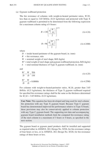
![16.1-255
Specification for Structural Steel Buildings, August 1, 2022
American Institute of Steel Construction
User Note: The attachment of the Type X gypsum board protection for the
steel columns must be done in accordance with the referenced UL assemblies.
UL X526 is applicable only when exterior steel covers are installed over the
gypsum board; otherwise, ANSI/UL 263, Design No. X528, describes the
more general gypsum board installation.
(b) Sprayed and intumescent or mastic fire-resistant materials
The fire resistance of columns protected with sprayed or intumescent or mastic
fire-resistant coatings shall be determined on the basis of standard fire-resistance-
rated assemblies, any associated computations, and limits as provided in the
applicable rated assemblies.
The fire resistance of wide-flange columns protected with sprayed fire-resistant
materials is permitted to be determined as follows:
R C
W
D
C h
=
+
1 2 (A-4-26)
R C
W
D
C h
=
+
3 4 (A-4-26M)
where
C1, C2, C3, and C4 =
material-dependent constants prescribed in specified rated
assembly
D = heated perimeter of the column, in. (mm)
R = fire resistance, min
W = weight of columns, lb/ft (kg/m)
h = thickness of sprayed fire-resistant material, in. (mm)
The material-dependent constants, C1, C2, C3, and C4, shall be determined for
specific fire-resistant materials on the basis of standard fire endurance tests. The
computational usage for each correlation, protection product, and its material-
dependent constants shall be limited to the range of their underlying fire test
basis reflected in the selected rated assembly.
User Note: The fire-resistance-rated steel column assemblies, published
by UL and by other test laboratories, will often include such interpolation
equations and specific constants that depend on the particular fire-protection
product. The applicability limits of each given design correlation relative to
the column assembly, sprayed fire-resistant protection product, W D, rating
duration, minimum required thickness, and similar properties, must be fol-
lowed to remain within the range of the existing fire test data range.
App. 4.3.] DESIGN BY QUALIFICATION TESTING
Part 16.1 Appendix A1-A4 (195-266).indd 255
Part 16.1 Appendix A1-A4 (195-266).indd 255 2023-01-10 8:25 PM
2023-01-10 8:25 PM](https://image.slidesharecdn.com/aisc360-22specificationforstructuralsteelbuildings-231108145904-1b416cfe/85/AISC-360-22-Specification-for-Structural-Steel-Buildings-pdf-323-320.jpg)
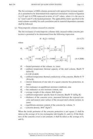
![16.1-257
Specification for Structural Steel Buildings, August 1, 2022
American Institute of Steel Construction
User Note: The variables in these equations are illustrated in the following
figures.
(a) Precast concrete (b) Concrete-encased (c) Concrete-encased
column covers HSS wide-flange shape
For wide-flange columns completely encased in concrete with all reentrant
spaces filled, the thermal capacity of the concrete within the reentrant spaces is
permitted to be added to the ambient thermal capacity of the steel column, as
follows:
H W
p c
b d A
c c
f s
= +
−
( )
0 11
144
. (A-4-29)
H W
p c
b d A
c c
f s
= +
−
( )
0 46
1000 000
. (A-4-29M)
where
As = area of the steel column, in.2 (mm2)
bf = width of the column flange, in. (mm)
d = depth of the column, in. (mm)
User Note: It is conservative to neglect this additional concrete term in the
column fire-resistance calculation.
In the absence of more specific data for the ambient properties of the concrete
encasement, it is permitted to use the values provided in Table A-4.3.2.
User Note: The estimated free moisture content of concrete given in Table
A-4.3.2 may not be appropriate for all conditions, particularly for older con-
crete that has already been in service for a longer time. For these and similar
situations of uncertainty, it is conservative to not rely on this beneficial effect
of the free moisture and to assume the concrete is completely dry with m = 0
for fire resistance of R = Ro.
(d) Noncomposite columns encased in masonry units of concrete or clay
The fire resistance of noncomposite columns protected by encasement with
concrete masonry units or with clay masonry units is permitted to be determined
from the following expression:
App. 4.3.] DESIGN BY QUALIFICATION TESTING
Part 16.1 Appendix A1-A4 (195-266).indd 257
Part 16.1 Appendix A1-A4 (195-266).indd 257 2023-01-10 8:25 PM
2023-01-10 8:25 PM](https://image.slidesharecdn.com/aisc360-22specificationforstructuralsteelbuildings-231108145904-1b416cfe/85/AISC-360-22-Specification-for-Structural-Steel-Buildings-pdf-325-320.jpg)
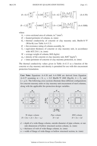
![16.1-259
Specification for Structural Steel Buildings, August 1, 2022
American Institute of Steel Construction
TABLE A-4.3.2
Ambient Properties of Concrete Encasement for
Steel Column Fire Resistance
Property
Normal Weight
Concrete
Lightweight
Concrete
Thermal conductivity, Kc
0.95 Btu/hr-ft-°F
(1.64 W/m-K)
0.35 Btu/hr-ft-°F
(0.61 W/m-K)
Specific heat, cc
0.20 Btu/lb-°F
(0.840 kJ/kg-K)
0.20 Btu/lb-°F
(0.840 kJ/kg-K)
Density, pc
145 lb/ft3
(2 300 kg/m3)
110 lb/ft3
(1 800 kg/m3)
Equilibrium (free) moisture content, m,
by volume
4% 5%
TABLE A-4.3.3
Thermal Conductivity of Masonry Units for Steel
Column Encasement
Unit Density,
dm, lb/ft3 (kg/m3)
Unit Thermal Conductivity
Kc, Btu/hr-ft-°
°F (W/m-K)
Concrete Masonry Units
80 (1 300) 0.207 (0.36)
85 (1 400) 0.228 (0.40)
90 (1 400) 0.252 (0.44)
95 (1 500) 0.278 (0.48)
100 (1 600) 0.308 (0.53)
105 (1 700) 0.340 (0.59)
110 (1 800) 0.376 (0.65)
115 (1 800) 0.416 (0.72)
120 (1 900) 0.459 (0.80)
125 (2 000) 0.508 (0.88)
130 (2 100) 0.561 (0.97)
135 (2 200) 0.620 (1.1)
140 (2 200) 0.685 (1.2)
145 (2 300) 0.758 (1.3)
150 (2 400) 0.837 (1.5)
Clay Masonry Units
120 (1 900) 1.25 (2.2)
130 (2 100) 2.25 (3.9)
App. 4.3.] DESIGN BY QUALIFICATION TESTING
Part 16.1 Appendix A1-A4 (195-266).indd 259
Part 16.1 Appendix A1-A4 (195-266).indd 259 2023-01-10 8:25 PM
2023-01-10 8:25 PM](https://image.slidesharecdn.com/aisc360-22specificationforstructuralsteelbuildings-231108145904-1b416cfe/85/AISC-360-22-Specification-for-Structural-Steel-Buildings-pdf-327-320.jpg)
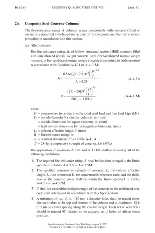
![16.1-261
Specification for Structural Steel Buildings, August 1, 2022
American Institute of Steel Construction
TABLE A-4.3.4
Values of Constant a for Normal Weight Concrete
Aggregate
Type
Concrete Fill
Type
Reinforcement
Ratio,
%
a
Circular
Columns
Square or
Rectangular
Columns
siliceous unreinforced NA 0.070 0.060
siliceous
steel-fiber-
reinforced
2 0.075 0.065
siliceous
steel-bar-
reinforced
1.5−3 0.080 0.070
3−5 0.085 0.070
carbonate unreinforced NA 0.080 0.070
carbonate
steel-fiber-
reinforced
2 0.085 0.075
carbonate
steel-bar-
reinforced
1.5−3 0.090 0.080
3−5 0.095 0.085
NA = not applicable
TABLE A-4.3.5
Limits for the Use of Equation A-4-31 Parameters
Parameter
Concrete Fill Type
Unreinforced
Steel-Fiber-
Reinforced
Steel-Bar-
Reinforced
R, hr ≤ 2 ≤ 3 ≤ 3
′
fc
, ksi 2.9−5.8 2.9−8.0 2.9−8.0
Lc, ft 6.5−13.0 6.5−15.0 6.5−15.0
D (round), in. 5.5−16.0 5.5−16.0 6.5−16.0
D (square or rectangular), in. 5.5−12.0 4.0−12.0 7.0−12.0
Reinforcement, % NA
2% of concrete
mix by mass
1.5−5%
of section area
Concrete cover, in. NA NA ≥ 1.0
NA = not applicable
(b) Composite columns encased in concrete
The fire resistance of composite columns fully encased within normal weight or
lightweight concrete and with no unfilled spaces is permitted to be determined
as the lesser of Equation A-4-30 or A-4-30M and the values in Table A-4.3.6.
App. 4.3.] DESIGN BY QUALIFICATION TESTING
Part 16.1 Appendix A1-A4 (195-266).indd 261
Part 16.1 Appendix A1-A4 (195-266).indd 261 2023-01-10 8:25 PM
2023-01-10 8:25 PM](https://image.slidesharecdn.com/aisc360-22specificationforstructuralsteelbuildings-231108145904-1b416cfe/85/AISC-360-22-Specification-for-Structural-Steel-Buildings-pdf-329-320.jpg)
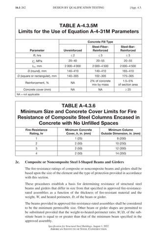
![16.1-263
Specification for Structural Steel Buildings, August 1, 2022
American Institute of Steel Construction
The provisions in this section apply to beams and girders protected with sprayed or
intumescent or mastic fire-resistant materials.
Larger or smaller composite or noncomposite beam and girder shapes protected with
sprayed fire-resistant materials are permitted to be substituted for beams specified in
approved unrestrained or restrained fire-resistance-rated assemblies, provided that
the thickness of the fire-resistant material is adjusted in accordance with Equation
A-4-32 or A-4-32M.
The use of these equations shall be limited by all of the following conditions:
(a)
The weight-to-heated-perimeter ratio for the substitute beam or girder, W D
1 1,
shall be not less than 0.37 (U.S. customary units) or 0.022 (SI units).
(b)
The thickness of fire-protection materials calculated for the substitute beam or
girder, T1, shall be not less than a in. (10 mm).
(c)
The unrestrained or restrained beam rating shall be not less than 1 hour.
(d)
Where used to adjust the material thickness for a restrained beam, the use of this
procedure is limited to sections classified as compact.
h
h W D
W D
2
1 1 1
2 2
0 60
0 60
=
( )+
( )+
.
.
(A-4-32)
h
h W D
W D
2
1 1 1
2 2
0 036
0 036
=
( )+
( )+
.
.
(A-4-32M)
where
D = heated perimeter of the beam, in. (mm)
W = weight of the beam or girder, lb/ft (kg/m)
h = thickness of sprayed fire-resistant material, in. (mm)
Subscript 1 refers to the substitute beam or girder and the required thickness of fire-
resistant material.
Subscript 2 refers to the beam and fire-resistant material thickness in the approved
assembly.
User Note: This substitution equation based on W D for beams protected with
spray-applied fire-resistive materials was developed by UL with the given limita-
tions. The minimum W D ratio of 0.37 (0.022) prevents the use of this equation
for determining the fire resistance of very small shapes that have not been tested.
The a in. (10 mm) minimum thickness of protection is a practical application
limit based upon the most commonly used spray-applied fire protection materials.
The fire resistance of composite or noncomposite beams and girders protected with
intumescent or mastic fire-resistant coatings shall be determined on the basis of
standard fire-resistance-rated assemblies, and associated computations and limits as
provided in the applicable rated assemblies.
App. 4.3.] DESIGN BY QUALIFICATION TESTING
Part 16.1 Appendix A1-A4 (195-266).indd 263
Part 16.1 Appendix A1-A4 (195-266).indd 263 2023-01-10 8:25 PM
2023-01-10 8:25 PM](https://image.slidesharecdn.com/aisc360-22specificationforstructuralsteelbuildings-231108145904-1b416cfe/85/AISC-360-22-Specification-for-Structural-Steel-Buildings-pdf-331-320.jpg)
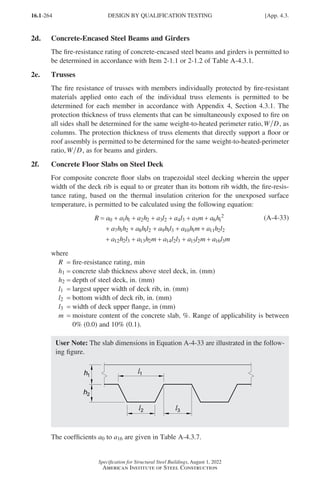
![16.1-265
Specification for Structural Steel Buildings, August 1, 2022
American Institute of Steel Construction
TABLE A-4.3.7
Coefficients a0 to a16 for Use with Equation A-4-33
Coefficient
Coefficient Value
Normal weight concrete Lightweight concrete
a0 38.6 min 68.7 min
a1 -5.08 min/in. (-0.2 min/mm) -36.58 min/in. (-1.44 min/mm)
a2 -1.45 min/in. (-0.057 min/mm) -2.79 min/in. (-0.11 min/mm)
a3 -3.30 min/in. (-0.13 min/mm) -12.70 min/in. (-0.5 min/mm)
a4 -2.08 min/in. (-0.082 min/mm) 20.07 min/in. (0.79 min/mm)
a5 -118.1 min -784.2 min
a6 4.06 min/in.2 (0.0063 min/mm2) 8.84 min/in.2 (0.014 min/mm2)
a7 1.48 min/in.2 (0.0023 min/mm2) 3.61 min/in.2 (0.0056 min/mm2)
a8 1.87 min/in.2 (0.0029 min/mm2) 3.68 min/in.2 (0.0057 min/mm2)
a9 0 -2.39 min/in.2 (-0.0037 min/mm2)
a10 263.1 min/in. (10 min/mm) 444.5 min/in. (18 min/mm)
a11 1.16 min/in.2 (0.0018 min/mm2) 2.06 min/in.2 (0.0032 min/mm2)
a12 0 -3.42 min/in.2 (-0.0053 min/mm2)
a13 0 91.44 min/in. (3.6 min/mm)
a14 -0.65 min/in.2 (-0.001 min/mm2) -0.97 min/in.2 (-0.0015 min/mm2)
a15 0 42.42 min/in. (1.67 min/mm)
a16 0 -66.04 min/in. (-2.6 min/mm)
User Note: If moisture content values are not available, m = 4% can be used for
normal weight concrete, and m = 5% can be used for lightweight concrete, con-
sistent with Annex D of Eurocode 4. Dry conditions (m = 0%) will yield the most
conservative fire-resistance rating.
2g. Composite Plate Shear Walls
For unprotected composite plate shear walls meeting the requirements of Chapter I
and satisfying the following conditions, the fire-resistance rating shall be determined
in accordance with Equation A-4-34 or A-4-34M.
(a) Wall slenderness ratio, L tsc, is less than or equal to 20
(b) Axial load ratio, P P
u n, is less than or equal to 0.2
(c) Wall thickness, tsc, is greater than or equal to 8 in. (200 mm)
R
P
P
t
u
n
L t
sc
sc
= −
+
−
−
18 5 15
1 9
8
1
0 24
230
.
.
.
(A-4-34)
App. 4.3.] DESIGN BY QUALIFICATION TESTING
Part 16.1 Appendix A1-A4 (195-266).indd 265
Part 16.1 Appendix A1-A4 (195-266).indd 265 2023-01-10 8:25 PM
2023-01-10 8:25 PM](https://image.slidesharecdn.com/aisc360-22specificationforstructuralsteelbuildings-231108145904-1b416cfe/85/AISC-360-22-Specification-for-Structural-Steel-Buildings-pdf-333-320.jpg)
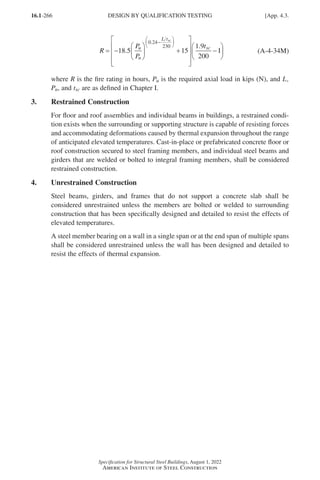
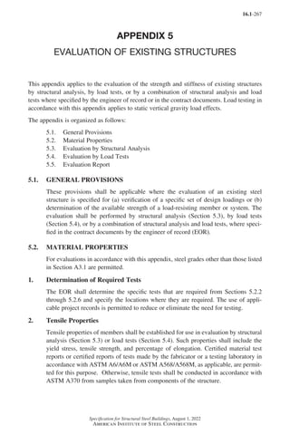
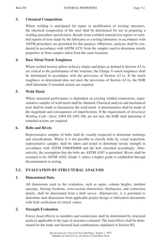
![16.1-269
Specification for Structural Steel Buildings, August 1, 2022
American Institute of Steel Construction
Table A-5.3.1
Nominal Strength of Rivets
Description of Rivet
Nominal Tensile Strength,
Fnt, ksi (MPa)[a]
Nominal Shear Strength,
Fnv, ksi (MPa)[b]
A502, Grade 1, hot-driven rivets 45 (310) 25 (170)
[a]Static loading only.
[b]Refer to Table J3.2, footnote c.
The available strength of members and connections shall be determined from appli-
cable provisions of Chapters B through K and Appendix 5 of this Specification.
2a. Rivets
The design tensile or shear strength, φRn, and the allowable tensile or shear strength,
Rn Ω, of a driven rivet shall be determined according to Section J3.7, and driven
rivets under combined tension and shear shall satisfy the requirements of Section
J3.8,
where
Ab = nominal body area of undriven rivet, in.2 (mm2)
Fnt = nominal tensile strength of the driven rivet from Table A-5.3.1, ksi (MPa)
Fnv = nominal shear strength of the driven rivet from Table A-5.3.1, ksi (MPa)
3. Serviceability Evaluation
Where required, the deformations at service loads shall be calculated and reported.
5.4. EVALUATION BY LOAD TESTS
1. General Requirements
This section applies only to static vertical gravity loads applied to existing roofs or
floors.
Where load tests are used, the EOR shall first analyze the structure, prepare a testing
plan, and develop a written procedure for the test. The plan shall consider collapse
and/or excessive levels of permanent deformation, as defined by the EOR, and shall
include procedures to preclude either occurrence during testing.
2. Determination of Load Rating by Testing
To determine the load rating of an existing floor or roof structure by testing, a test
load shall be applied incrementally in accordance with the EOR’s plan. The structure
shall be visually inspected for signs of distress or imminent failure at each load level.
Measures shall be taken to prevent collapse if these or any other unusual conditions
are encountered.
App. 5.4.] EVALUATION BY LOAD TESTS
Part 16.1 Appendix A5-A8 (267-286).indd 269
Part 16.1 Appendix A5-A8 (267-286).indd 269 2023-01-10 8:28 PM
2023-01-10 8:28 PM](https://image.slidesharecdn.com/aisc360-22specificationforstructuralsteelbuildings-231108145904-1b416cfe/85/AISC-360-22-Specification-for-Structural-Steel-Buildings-pdf-337-320.jpg)
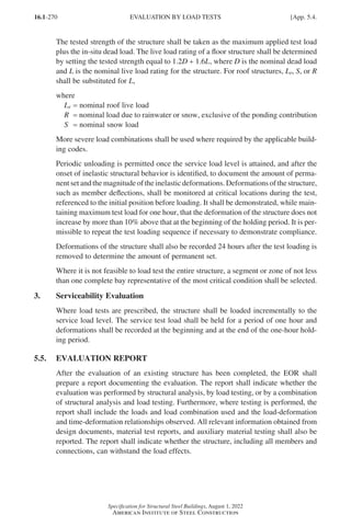

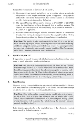
![16.1-273
Specification for Structural Steel Buildings, August 1, 2022
American Institute of Steel Construction
and the required shear stiffness of the bracing system is
βbr
r
br
P
L
=
1 2
φ
(LRFD) (A-6-2a)
βbr
r
br
P
L
=
Ω
2
(ASD) (A-6-2b)
φ = 0.75 (LRFD) Ω = 2.00 (ASD)
where
Lbr = unbraced length within the panel under consideration, in. (mm)
Pr =
required axial strength of the column within the panel under consideration
using LRFD or ASD load combinations, kips (N)
2. Point Bracing
In the direction perpendicular to the longitudinal axis of the column, the required
strength of end and intermediate point braces is
P P
br r
= 0 01
. (A-6-3)
and the required stiffness of the brace is
β
φ
br
r
br
P
L
=
1 8
(LRFD) (A-6-4a)
βbr
r
br
P
L
=
Ω
8
(ASD) (A-6-4b)
φ = 0.75 (LRFD) Ω = 2.00 (ASD)
where
Lbr = unbraced length adjacent to the point brace, in. (mm)
Pr =
largest of the required axial strengths of the column within the unbraced
lengths adjacent to the point brace using LRFD or ASD load combinations,
kips (N)
When the unbraced lengths adjacent to a point brace have different P L
r br values, the
larger value shall be used to determine the required brace stiffness.
For intermediate point bracing of an individual column, Lbr in Equations A-6-4a or
A-6-4b need not be taken as less than the maximum effective length, Lc, permitted
for the column based upon the required axial strength, Pr.
6.3. BEAM BRACING
Beams shall be restrained against rotation about their longitudinal axis at points of
support. When a braced point is assumed in the design between points of support,
lateral bracing, torsional bracing, or a combination of the two shall be provided to
limit the relative displacement of the top and bottom flanges (i.e., to resist twist).
In members subjected to double curvature bending, the inflection point shall not be
considered a braced point unless bracing is provided at that location.
App. 6.3.] BEAM BRACING
Part 16.1 Appendix A5-A8 (267-286).indd 273
Part 16.1 Appendix A5-A8 (267-286).indd 273 2023-01-10 8:28 PM
2023-01-10 8:28 PM](https://image.slidesharecdn.com/aisc360-22specificationforstructuralsteelbuildings-231108145904-1b416cfe/85/AISC-360-22-Specification-for-Structural-Steel-Buildings-pdf-341-320.jpg)
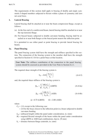
![16.1-275
Specification for Structural Steel Buildings, August 1, 2022
American Institute of Steel Construction
1b. Point Bracing
In the direction perpendicular to the longitudinal axis of the beam, the required
strength of end and intermediate point braces is
P
M C
h
br
r d
o
=
0 02
. (A-6-7)
and the required stiffness of the brace is
β
φ
br
r d
br o
M C
L h
=
1 10
(LRFD) (A-6-8a)
βbr
r d
br o
M C
L h
=
Ω
10
(ASD) (A-6-8b)
φ = 0.75 (LRFD) Ω = 2.00 (ASD)
where
Lbr = unbraced length adjacent to the point brace, in. (mm)
Mr =
largest of the required flexural strengths of the beam within the unbraced
lengths adjacent to the point brace using LRFD or ASD load combinations,
kip-in. (N-mm)
When the unbraced lengths adjacent to a point brace have different M L
r br values, the
larger value shall be used to determine the required brace stiffness.
For intermediate point bracing of an individual beam, Lbr in Equations A-6-8a or
A-6-8b need not be taken as less than the maximum effective length, Lb, permitted
for the beam based upon the required flexural strength, Mr.
2. Torsional Bracing
It is permitted to attach torsional bracing at any cross-section location, and it need
not be attached near the compression flange.
User Note: Torsional bracing can be provided as point bracing, such as cross-
frames, moment-connected beams, or vertical diaphragm elements, or as continu-
ous bracing, such as slabs or decks.
2a. Point Bracing
About the longitudinal axis of the beam, the required flexural strength of the brace is
M
L
nEI
M
C
L
h
M
br
yeff
r
b
br
o
r
=
≥
3 6
500
0 02
2
.
. (A-6-9)
and the required flexural stiffness of the brace is
β
β
β
β
br
T
T
=
−
1
sec
(A-6-10)
App. 6.3.] BEAM BRACING
Part 16.1 Appendix A5-A8 (267-286).indd 275
Part 16.1 Appendix A5-A8 (267-286).indd 275 2023-01-29 12:21 PM
2023-01-29 12:21 PM](https://image.slidesharecdn.com/aisc360-22specificationforstructuralsteelbuildings-231108145904-1b416cfe/85/AISC-360-22-Specification-for-Structural-Steel-Buildings-pdf-343-320.jpg)
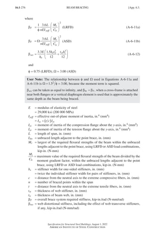
![16.1-277
Specification for Structural Steel Buildings, August 1, 2022
American Institute of Steel Construction
User Note: If βsec βT, Equation A-6-10 is negative, which indicates that tor-
sional beam bracing will not be effective due to inadequate web distortional
stiffness.
User Note: For doubly symmetric members, c = t and Iyeff = out-of-plane moment
of inertia, Iy, in.4 (mm4).
When required, a web stiffener shall extend the full depth of the braced member and
shall be attached to the flange if the torsional brace is also attached to the flange.
Alternatively, it is permissible to stop the stiffener short by a distance equal to 4tw
from any beam flange that is not directly attached to the torsional brace.
When the expression, M C L
r b br
( )2
, within the unbraced lengths adjacent to a point
brace, has different values, the larger value shall be used to determine the required
brace strength and stiffness.
In Equation A-6-9, Lbr need not be taken as less than the maximum unbraced length
permitted for the beam based upon the required flexural strength, Mr.
2b. Continuous Bracing
For continuous torsional bracing:
(a)
The brace strength requirement per unit length along the beam shall be taken
as Equation A-6-9 divided by the maximum unbraced length permitted for
the beam based upon the required flexural strength, Mr. The required flexural
strength, Mr, shall be taken as the maximum value throughout the beam span.
(b) The brace stiffness requirement per unit length shall be given by Equations A-6-10
and A-6-11 with L n = 1.0.
(c) The web distortional stiffness shall be taken as
βsec
w
o
Et
h
=
3 3
12
3
.
(A-6-13)
6.4. BEAM-COLUMN BRACING
For bracing of beam-columns, the required strength and stiffness for the axial force
shall be determined as specified in Section 6.2, and the required strength and stiffness
for flexure shall be determined as specified in Section 6.3. The values so determined
shall be combined as follows:
(a)
When panel bracing is used, the required strength shall be taken as the sum of the
values determined using Equations A-6-1 and A-6-5, and the required stiffness
shall be taken as the sum of the values determined using Equations A-6-2 and
A-6-6.
(b)
When point bracing is used, the required strength shall be taken as the sum of the
values determined using Equations A-6-3 and A-6-7, and the required stiffness
shall be taken as the sum of the values determined using Equations A-6-4 and
App. 6.4.] BEAM-COLUMN BRACING
Part 16.1 Appendix A5-A8 (267-286).indd 277
Part 16.1 Appendix A5-A8 (267-286).indd 277 2023-01-10 8:28 PM
2023-01-10 8:28 PM](https://image.slidesharecdn.com/aisc360-22specificationforstructuralsteelbuildings-231108145904-1b416cfe/85/AISC-360-22-Specification-for-Structural-Steel-Buildings-pdf-345-320.jpg)
![16.1-281
Specification for Structural Steel Buildings, August 1, 2022
American Institute of Steel Construction
(b)
The required axial compressive strengths in nominally horizontal members in
moment frames subjected to bending satisfy the following limitation:
αPr ≤ 0.08Pe (A-7-1)
where
α = 1.0 (LRFD); α = 1.6 (ASD)
Pe = π2 2
EI L , kips (N)
E = modulus of elasticity of steel, ksi (MPa)
=
29,000 ksi (200 000 MPa)
I = moment of inertia in the plane of bending, in.4 (mm4)
L = height of story, in. (mm)
Pr =
required axial compressive strength using LRFD or ASD load combina-
tions, kips (N)
(c)
The ratio of maximum second-order drift to maximum first-order drift (both
determined for LRFD load combinations or 1.6 times ASD load combinations,
with stiffness not adjusted as specified in Section C2.3) in all stories is equal to
or less than 1.5.
User Note: The ratio of second-order drift to first-order drift in a story may
be taken as the B2 multiplier, calculated as specified in Appendix 8.
(d)
The required axial compressive strengths of all members whose flexural stiff-
nesses are considered to contribute to the lateral stability of the structure satisfy
the following limitation:
αPr ≤ 0.5Pns (A-7-2)
where
Pns =
cross-section compressive strength; for nonslender-element sections,
Pns = FyAg, and for slender-element sections, Pns = FyAe, where Ae is as
defined in Section E7 with Fn = Fy, kips (N)
2. Required Strengths
The required strengths of components shall be determined from a first-order analysis,
with additional requirements (a) and (b) given in the following. The analysis shall
consider flexural, shear, and axial member deformations, and all other deformations
that contribute to displacements of the structure.
(a)
All load combinations shall include an additional lateral load, Ni, applied in
combination with other loads at each level of the structure:
N L Y Y
i i i
. ( ) .
= ≥
2 1 42
α ∆ 0 00 (A-7-3)
where
α = 1.0 (LRFD); α = 1.6 (ASD)
Yi =
gravity load applied at level i from the LRFD load combination or ASD
load combination, as applicable, kips (N)
∆ L = maximum ratio of ∆ to L for all stories in the structure
App. 7.3.] FIRST-ORDER ANALYSIS METHOD
Part 16.1 Appendix A5-A8 (267-286).indd 281
Part 16.1 Appendix A5-A8 (267-286).indd 281 2023-01-10 8:28 PM
2023-01-10 8:28 PM](https://image.slidesharecdn.com/aisc360-22specificationforstructuralsteelbuildings-231108145904-1b416cfe/85/AISC-360-22-Specification-for-Structural-Steel-Buildings-pdf-349-320.jpg)
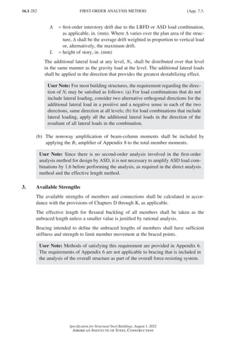
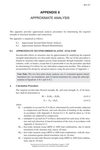
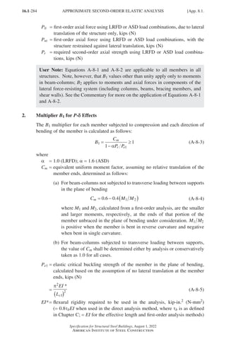
![16.1-285
Specification for Structural Steel Buildings, August 1, 2022
American Institute of Steel Construction
E = modulus of elasticity of steel
= 29,000 ksi (200 000 MPa)
I = moment of inertia in the plane of bending, in.4 (mm4)
Lc1 =
effective length in the plane of bending, calculated based on the assump-
tion of no lateral translation at the member ends, set equal to the laterally
unbraced length of the member unless analysis justifies a smaller value, in.
(mm)
It is permitted to use the first-order estimate of Pr (i.e., P P P
r nt lt
= + ) in Equation
A-8-3.
3. Multiplier B2 for P-D
D Effects
The B2 multiplier for each story and each direction of lateral translation is calculated
as follows:
B
P
P
story
e story
2
1
1
1
=
−
≥
α
(A-8-6)
where
α = 1.0 (LRFD); α = 1.6 (ASD)
Pstory =
total vertical load supported by the story using LRFD or ASD load com-
binations, as applicable, including loads in columns that are not part of
the lateral force-resisting system, kips (N)
Pe story =
elastic critical buckling strength for the story in the direction of trans-
lation being considered, kips (N), determined by sidesway buckling
analysis or as given in Equation A-8-7.
= R
HL
M
H
∆
(A-8-7)
H =
total story shear, in the direction of translation being considered, pro-
duced by the lateral forces used to compute DH, kips (N)
L = height of story, in. (mm)
RM = 1 0 15
− ( )
. P P
mf story (A-8-8)
Pmf =
total vertical load in columns in the story that are part of moment frames,
if any, in the direction of translation being considered (= 0 for braced-
frame systems), kips (N)
∆H =
first-order interstory drift, in the direction of translation being con-
sidered, due to lateral forces, in. (mm), computed using the stiffness
required to be used in the analysis. (When the direct analysis method is
used, stiffness is reduced according to Section C2.3.) Where ∆H varies
over the plan area of the structure, it shall be the average drift weighted
in proportion to vertical load or, alternatively, the maximum drift.
User Note: The story gravity load (Pstory and Pmf) includes loading from levels
above and on nonframe columns and walls, and the weight of wall panels later-
ally supported by the lateral force-resisting system; it need not include the vertical
component of the seismic force.
App. 8.1.] APPROXIMATE SECOND-ORDER ELASTIC ANALYSIS
Part 16.1 Appendix A5-A8 (267-286).indd 285
Part 16.1 Appendix A5-A8 (267-286).indd 285 2023-01-10 8:28 PM
2023-01-10 8:28 PM](https://image.slidesharecdn.com/aisc360-22specificationforstructuralsteelbuildings-231108145904-1b416cfe/85/AISC-360-22-Specification-for-Structural-Steel-Buildings-pdf-353-320.jpg)
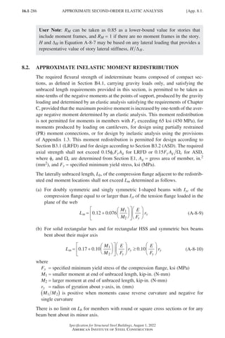
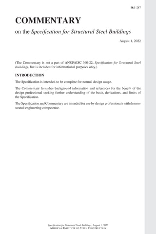
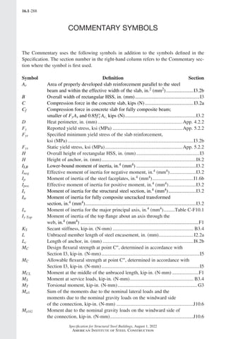
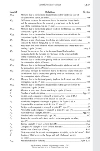
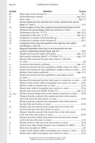
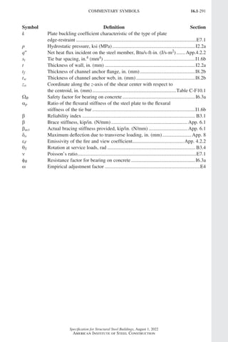
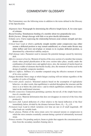
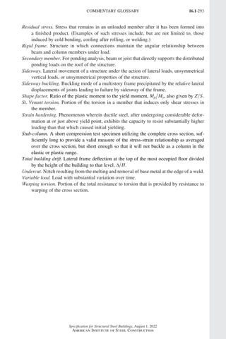

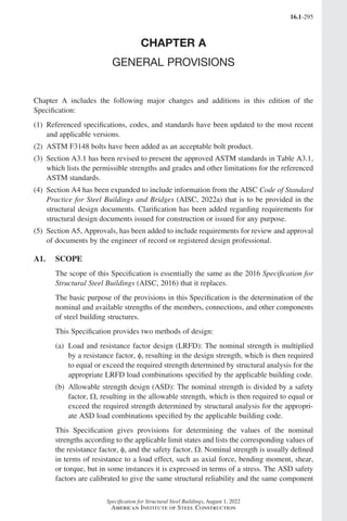
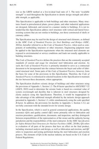
![16.1-297
Specification for Structural Steel Buildings, August 1, 2022
American Institute of Steel Construction
A2. REFERENCED SPECIFICATIONS, CODES, AND STANDARDS
Section A2 provides references to documents cited in this Specification. The date of
the referenced document found in this Specification is the intended date referenced in
this Commentary unless specifically indicated otherwise. Note that not all grades of
a particular material specification are necessarily approved for use according to this
Specification. For a list of approved materials and grades, see Section A3.
A3. MATERIAL
1. Structural Steel Materials
1a. Listed Materials
There are hundreds of steel materials and products. This Specification lists those
products/materials that are commonly useful to structural engineers and those that
have a history of satisfactory performance as anticipated in the other provisions of
the Specification. Other materials may be suitable for specific applications, but the
evaluation of those materials is the responsibility of the engineer specifying them. In
addition to typical strength properties, considerations for materials may include, but
are not limited to, strength properties in transverse directions, ductility, formability,
soundness, weldability including sensitivity to thermal cycles, notch toughness, and
other forms of crack sensitivity, coatings, and corrosivity. Consideration for product
form may include material considerations in addition to effects of production, toler-
ances, testing, reporting, and surface profiles.
Table A3.1 includes information concerning permitted grades and strengths and other
limitations that are beyond what has historically been presented. ASTM A572/A572M
Type 5 is not included due to potential problems associated with welding. HSS are
limited to electric-resistance welding (ERW) or seamless to prohibit the use of furnace
welding that may result in seams that do not achieve full strength of the base metal.
Materials used in the production of ASTM A1065/A1065M are limited because other
materials listed in ASTM A1065/A1065M do not have a history of satisfactory perfor-
mance when used in buildings. Welding quenched and tempered steels such as ASTM
A514/A514M can be challenging due to their higher strength and the need to control
welding procedures more carefully. If proper procedures are not followed, high hard-
ness in the heat affected zone is possible. This can lead to premature or even immediate
failure. While this should not prohibit its use, the engineer should consult the steel pro-
ducer if they choose to use the material. ASTM A709/A709M Grade 50CR (345CR)
is a stainless steel and is not approved for use with the Specification.
Hot-Rolled Shapes. The commentary herein contains information relevant to hot-
rolled shapes, as well as plates. Particularly, in segments of this commentary where
the term “rolled steel” or “hot-rolled steel” is used, the information may be appli-
cable to both shapes and plates. The grades of steel approved for use under this
Specification, covered by ASTM Specifications, extend to a yield stress of 80 ksi
(550 MPa) for rolled shapes and 100 ksi (690 MPa) for plates. Some of the ASTM
Specifications specify a minimum yield point, while others specify a minimum yield
strength. The term “yield stress” is used in this Specification as a generic term to
denote either the yield point or the yield strength.
Comm. A3.] MATERIAL
Part 16.1 Commentary A-E (295-369).indd 297
Part 16.1 Commentary A-E (295-369).indd 297 2023-01-23 6:59 PM
2023-01-23 6:59 PM](https://image.slidesharecdn.com/aisc360-22specificationforstructuralsteelbuildings-231108145904-1b416cfe/85/AISC-360-22-Specification-for-Structural-Steel-Buildings-pdf-365-320.jpg)
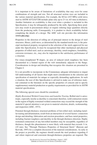
![16.1-299
Specification for Structural Steel Buildings, August 1, 2022
American Institute of Steel Construction
steel producer can supply steel with improved through-thickness properties by imple-
menting additional metallurgical or heat treatment processing.
The geometry of the welded connections should be designed to avoid through-thick-
ness tensile stresses and configure the joint to best limit restraint and reduce weld
metal volume. See recommendations in AWS D1.1/D1.1M Commentary C-4.7.3
(AWS, 2020) and “Commentary on Highly Restrained Welded Connections” (AISC,
1973).
Other measures the engineer can specify to mitigate through-thickness challenges
are listed below:
(1)
Expand use of ultrasonic testing (UT) to inspect the steel at the location of the
weld and surrounding area before and after welding. AISC Seismic Provisions
for Structural Steel Buildings (AISC, 2022c) Section J7.2c requires the UT of
base metal thicker than 12 in. (38 mm) after joint (weld) completion behind and
adjacent to the fusion line, and refers to AWS D1.1/D1.1M (AWS, 2020), Table
8.2, for acceptance criteria.
(2)
Specify nondestructive examination (NDE) during the fabrication process.
Visual examination, liquid penetrant, and magnetic particle testing can be used
to identify surface discontinuities. UT can be used to detect internal discontinui-
ties. Plate can be mill ordered with supplementary requirement S8, “Ultrasonic
Examination,” of ASTM A6/A6M, specifically ASTM A435/A435M (ASTM,
2017b) and ASTM A578/A578M (ASTM, 2017c). Radiography is not recom-
mended because the relevant orientation of the discontinuities of interest are
difficult to detect with this method. Results of NDE will enable the fabricator to
locate steel members such that particularly susceptible material is not subjected
to excessive through-thickness strains.
(3)
Specify through-thickness tensile testing. For steel plates this is achieved in
accordance with ASTM A770/A770M (ASTM, 2018b). This test evaluates sus-
ceptibility to lamellar tearing, where a minimum area reduction value of 20% has
generally been shown to provide adequate ductility to help mitigate the problem,
though a minimum value of 15% may be acceptable. CEN (2005c) gives a pro-
cedure for specifying area reductions of 15% and greater.
Including any of these measures should be carefully considered with input from the
contractor and steel supplier regarding the cost, ease of implementation, and relative
effectiveness.
Fracture Control Design for Service Conditions. For especially demanding service
conditions, such as structures exposed to low temperatures, particularly those with
cyclic or impact loading, the specification of steels with superior notch toughness
may be warranted. However, for most buildings, the steel is relatively warm, strain
rates are essentially static, and the stress intensity and number of cycles of full design
stress are low. Accordingly, the probability of fracture in most building structures is
low. Good workmanship and good design details incorporating joint geometry that
avoids severe stress concentrations are generally the most effective means of provid-
ing fracture-resistant construction (AASHTO, 2014).
Comm. A3.] MATERIAL
Part 16.1 Commentary A-E (295-369).indd 299
Part 16.1 Commentary A-E (295-369).indd 299 2023-01-26 11:11 AM
2023-01-26 11:11 AM](https://image.slidesharecdn.com/aisc360-22specificationforstructuralsteelbuildings-231108145904-1b416cfe/85/AISC-360-22-Specification-for-Structural-Steel-Buildings-pdf-367-320.jpg)
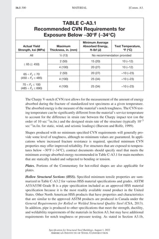
![16.1-301
Specification for Structural Steel Buildings, August 1, 2022
American Institute of Steel Construction
TABLE C-A3.2
Minimum Tensile Properties of HSS Steels
Specification Grade
Fy,
ksi (MPa)
Fu,
ksi (MPa)
ASTM A53/A53M B 35 (240) 60 (415)
ASTM A500/A500M
(square, rectangular, round)
B
C
46 (315)
50 (345)
58 (400)
62 (425)
ASTM A501/A501M
A
B
36 (250)
50 (345)
58 (400)
70 (485)
ASTM A618/A618M
(round)
I and II
[t ≤ 3
/4 in. (19 mm)]
III
50 (345)
50 (345)
70 (485)
65 (450)
ASTM A847/A847M − 50 (345) 70 (485)
CAN/CSA-G40.20/G40.21 350W 51 (350) 65 (450)
ASTM A1085/A1085M A 50 (345) 65 (450)
ASTM A1065/A1065M
50
50W
50 (345)
50 (345)
60 (415)
70 (480)
materials not specifically listed in Table A3.1 are permitted when suitability is deter-
mined by the engineer of record (EOR).
Round HSS can be readily obtained in ASTM A53/A53M material and ASTM
A500/A500M Grade C is also common. For rectangular HSS, ASTM A500/A500M
Grade C is the most commonly available material and a special order would be
required for any other material. Depending upon size, either welded or seamless
round HSS can be obtained. In North America, however, all ASTM A500/A500M
rectangular HSS for structural purposes are welded. Rectangular HSS differ from
box sections in that they have uniform thickness, except for some thickening in the
rounded corners.
Nominal strengths of directly welded T-, Y-, and K-connections of HSS have been
developed analytically and empirically. Connection deformation is anticipated and
is an acceptance limit for connection tests. Ductility is necessary to achieve the
expected deformations. The ratio of the specified minimum yield strength to the
specified minimum tensile strength (yield/tensile ratio) is one measure of material
ductility. Materials in HSS used in connection tests have had a yield/tensile ratio
of up to 0.80 and therefore that ratio has been adopted as a limit of applicability
for directly welded HSS connections. ASTM A500/A500M Grade A material does
not meet this ductility “limit of applicability” for direct connections in Chapter K.
ASTM A500/A500M Grade C has a yield/tensile ratio of 0.807 but it is reasonable
to use the rounding method described in ASTM E29 (ASTM, 2019c) and find this
material acceptable for use.
Comm. A3.] MATERIAL
Part 16.1 Commentary A-E (295-369).indd 301
Part 16.1 Commentary A-E (295-369).indd 301 2023-01-30 5:34 AM
2023-01-30 5:34 AM](https://image.slidesharecdn.com/aisc360-22specificationforstructuralsteelbuildings-231108145904-1b416cfe/85/AISC-360-22-Specification-for-Structural-Steel-Buildings-pdf-369-320.jpg)
![16.1-302
Specification for Structural Steel Buildings, August 1, 2022
American Institute of Steel Construction
Even though ASTM A501/A501M includes rectangular HSS, hot-formed rectangu-
lar HSS are not currently produced in the United States. The General Requirements
for Rolled or Welded Structural Quality Steel (CSA, 2013) includes Class C (cold-
formed) and Class H (cold-formed and stress relieved) HSS. Class H HSS have
relatively low levels of residual stress, which enhances their performance in com-
pression and may provide better ductility in the corners of rectangular HSS.
API 5L (API, 2012) is a line pipe specification that has some requirements for
mechanical characteristics that make it advantageous for use in specific structural
applications, such as in long span roofs with long unbraced lengths or large com-
posite columns in heavy unbraced frames. Note, however, that Section A3.1b states,
for materials not specifically listed in Table A3.1, suitability must be determined by
the EOR. The specified minimum yield strength of API 5L ranges from 25 to 80 ksi
(170 to 550 MPa) and the specified minimum tensile strength ranges from 45 to
90 ksi (310 to 620 MPa), depending on product specification level and material
grade. For Grades X42 and higher, additional elements may be used upon agreement
between the purchaser and the manufacturer; however, care should be exercised
in determining the alloying content for any given size and wall thickness of pipe,
because the addition of such otherwise desirable elements may affect the weldability
of the pipe. PSL2 pipe is a common structural choice and Grade X52 is prob-
ably the most common grade for structural purposes. Some pertinent mechanical
and geometric properties for PSL2 X52N are Fy = 52 ksi (360 MPa); Fu = 66 ksi
(460 MPa); toughness = 20 ft-lbf @ 32°F (27 J @ 0oC) for D ≤ 30 in. (750 mm); a
wall thickness lower tolerance of −10% for 3/16 in. t 19/32 in. (5 mm t 15 mm),
and -0.02 in. (-0.5 mm) for t 3/16 in. (t 5 mm); and a mass or area tolerance of
-3.5% for regular plain-ended pipe. With a diameter range from 13/32 in. to 84 in.
(10 mm to 2 100 mm), this high-quality pipe material addresses a frequent need for
either large diameter or thick-walled round hollow sections. Other special features
of PSL2 pipe are an upper bound on the yield strength [for example, for X52 the
minimum and maximum yield strengths are 52 ksi (360 MPa) and 76 ksi (520 MPa),
respectively], and a maximum yield-to-tensile stress ratio of 0.93 in the as-delivered
pipe [for D 12.75 in. (319 mm)].
1d. Rolled Heavy Shapes
The web-to-flange intersection and the web center of heavy hot-rolled shapes, as well
as the interior portions of heavy plates, may contain a more coarse grain structure
and/or lower notch toughness material than other areas of these products (Cattan,
1995; Jaquess and Frank, 1999). This is probably caused by ingot segregation, the
somewhat lesser deformation during hot rolling, higher finishing temperature, and
the slower cooling rate after rolling for these heavy sections. This characteristic is
not detrimental to suitability for compression members or for nonwelded members.
However, when heavy cross sections are joined by splices or connections using com-
plete-joint-penetration groove welds that extend through the coarser and/or lower
notch-tough interior portions, tensile stresses induced by weld shrinkage may result
in cracking. An example is a complete-joint-penetration groove welded connection
of a heavy cross-section beam to any column section. When members of lesser thick-
ness are joined by complete-joint-penetration groove welds, which induce smaller
MATERIAL [Comm. A3.
Part 16.1 Commentary A-E (295-369).indd 302
Part 16.1 Commentary A-E (295-369).indd 302 2023-01-23 6:59 PM
2023-01-23 6:59 PM](https://image.slidesharecdn.com/aisc360-22specificationforstructuralsteelbuildings-231108145904-1b416cfe/85/AISC-360-22-Specification-for-Structural-Steel-Buildings-pdf-370-320.jpg)
![16.1-303
Specification for Structural Steel Buildings, August 1, 2022
American Institute of Steel Construction
weld shrinkage strains, to the finer grained and/or more notch-tough surface material
of ASTM A6/A6M shapes and heavy built-up cross sections, the potential for crack-
ing is significantly lower. An example is a complete-joint-penetration groove welded
connection of a nonheavy cross-section beam to a heavy cross-section column.
For critical applications, such as primary tension members, material should be
specified to provide adequate notch toughness at service temperatures. Because of
differences in the strain rate between the Charpy V-notch (CVN) impact test and the
strain rate experienced in actual structures, the CVN test is conducted at a tempera-
ture higher than the anticipated service temperature for the structure. The location of
the CVN test specimens (“alternate core location”) is specified in ASTM A6/A6M,
Supplemental Requirement S30.
The notch toughness requirements of Sections A3.1d and A3.1e are intended only to
provide structural steel material with a nominal yield strength of 50 ksi with reason-
able notch toughness for ordinary service applications [enclosed structures or lowest
anticipated service temperature of 50°F (10°C) or higher]. For unusual applications,
low temperature service, and/or higher strength material, more restrictive require-
ments and/or notch toughness requirements for other section sizes and thicknesses
may be appropriate (Barsom and Rolfe, 1999). To minimize the potential for frac-
ture, the notch toughness requirements of Sections A3.1d and A3.1e must be used in
conjunction with good design and fabrication procedures. Specific requirements are
given in Sections J1.5, J1.6, J2.6, and J2.7.
1e. Built-Up Heavy Shapes
Portions of Commentary Section A3.1d for rolled heavy shapes are also applicable
for built-up heavy shapes.
2. Steel Castings and Forgings
Design and fabrication of cast and forged steel components are not covered in this
Specification.
Steel Castings. There are a number of ASTM Specifications for steel castings. The
Steel Founders’ Society of America (SFSA) Steel Castings Handbook (SFSA, 1995)
discusses a number of standards useful for steel structures. In addition to the require-
ments of this Specification, SFSA recommends that various other requirements be
considered for cast steel products. Continued quality assurance is critical to make
certain there is confidence in the cast product. This includes testing of first article
components as well as production testing. It may be appropriate to inspect the first
piece cast using magnetic particle inspection (MPI) in accordance with ASTM E125,
degree 1a, b, or c (ASTM, 2013). Radiographic inspection level III may be desirable
for the first piece cast. Ultrasonic testing (UT) in compliance with ASTM A609/
A609M (ASTM, 2012a) may be appropriate for the first cast piece over 6 in. (150
mm) thick. UT and MPI of production castings are also advisable. Design approval,
sample approval, periodic nondestructive testing, chemical testing, and selection of
the correct welding specification should be among the issues defined in the selection
and procurement of cast steel products. Refer to SFSA (1995) for design informa-
tion about cast steel products. For visual examination, refer to ASTM A802 (ASTM,
Comm. A3.] MATERIAL
Part 16.1 Commentary A-E (295-369).indd 303
Part 16.1 Commentary A-E (295-369).indd 303 2023-01-23 6:59 PM
2023-01-23 6:59 PM](https://image.slidesharecdn.com/aisc360-22specificationforstructuralsteelbuildings-231108145904-1b416cfe/85/AISC-360-22-Specification-for-Structural-Steel-Buildings-pdf-371-320.jpg)
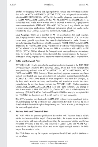
![16.1-305
Specification for Structural Steel Buildings, August 1, 2022
American Institute of Steel Construction
5. Consumables for Welding
The AWS filler metal specifications listed in Section A3.5 are general specifications
that include filler metal classifications suitable for building construction, as well
as classifications that may not be suitable for building construction. AWS D1.1/
D1.1M, Structural Welding Code—Steel (AWS, 2020) Table 5.4 lists the various
filler metals that may be used for prequalified welding procedure specifications, for
the various steels that are to be joined. This list specifically does not include various
classifications of filler metals that are not suitable for structural steel applications.
Filler metals listed under the various AWS A5 filler metal specifications may or may
not have specified notch toughness properties, depending on the specific electrode
classification. Section J2.6 identifies certain welded joints where notch toughness of
filler metal is needed in building construction. There may be other situations where
the EOR may elect to specify the use of filler metals with specified notch toughness
properties, such as for structures subjected to high loading rate, cyclic loading, or
seismic loading. Because AWS D1.1/D1.1M does not automatically require that the
filler metal used have specified notch toughness properties, it is important that filler
metals used for such applications be of an AWS classification, where such proper-
ties are required. This information can be found in the various AWS filler metal
specifications and is often contained on the filler metal manufacturer’s certificate of
conformance or product specification sheets.
When specifying filler metal and/or flux by AWS designation, the applicable stan-
dard specifications should be carefully reviewed to assure a complete understanding
of the designation reference. This is necessary because the AWS designation systems
are not consistent. For example, in the case of electrodes for shielded metal arc
welding, AWS A5.1/A5.1M, the first two or three digits indicate the nominal tensile
strength classification, in ksi, of the filler metal and the final two digits indicate the
type of coating. For metric designations, the first two digits times 10 indicate the
nominal tensile strength classification in MPa. In the case of mild steel electrodes
for submerged arc welding, AWS A5.17/A5.17M, the first one or two digits times
10 indicate the nominal tensile strength classification for both U.S. customary and
metric units, while the final digit or digits times 10 indicate the testing temperature
in °F for filler metal impact tests. In the case of low-alloy steel covered arc welding
electrodes, AWS A5.5/A5.5M, certain portions of the designation indicate a require-
ment for stress relief, while others indicate no stress relief requirement.
Engineers do not, in general, specify the exact filler metal to be employed on a par-
ticular structure. Rather, the decision as to which welding process and which filler
metal is to be utilized is usually left with the fabricator or erector. Codes restrict the
usage of certain filler metals or impose qualification testing to prove the suitability
of the specific electrode, so as to make certain that the proper filler metals are used.
A4. STRUCTURAL DESIGN DOCUMENTS AND SPECIFICATIONS
1. Structural Design Documents and Specifications Issued for Construction
This Specification provides minimum requirements that are deemed effective to
provide satisfactory results in steel buildings and other structures within the intended
Comm. A4.] STRUCTURAL DESIGN DOCUMENTS AND SPECIFICATIONS
Part 16.1 Commentary A-E (295-369).indd 305
Part 16.1 Commentary A-E (295-369).indd 305 2023-01-23 6:59 PM
2023-01-23 6:59 PM](https://image.slidesharecdn.com/aisc360-22specificationforstructuralsteelbuildings-231108145904-1b416cfe/85/AISC-360-22-Specification-for-Structural-Steel-Buildings-pdf-373-320.jpg)
![16.1-307
Specification for Structural Steel Buildings, August 1, 2022
American Institute of Steel Construction
Design of Structural Steel Connections. It is recognized that various means of des-
ignating and designing structural steel connections have been used in structural steel
construction. Therefore, it is important to address these means in this Commentary.
The Code of Standard Practice (AISC, 2022a) describes three options that can be
used. One of these options should be indicated for each connection in a project. It is
acceptable to group connection types and utilize a combination of these options for
the various connection types involved in a project.
When the EOR intends to provide complete connection design in the structural design
documents (described as Option 1 in the Code of Standard Practice), the design draw-
ings should include the following:
(a)
All weld types, sizes, lengths, and electrode specification tensile strengths
(b) All bolt sizes, locations, quantities, and grades
(c) All plate and angle sizes, thicknesses, dimensions, and grades
(d) All work point locations and related information
Welds should be specified as required by AWS D1.1/D1.1M (AWS, 2020). This
includes the following:
(1)
The effective weld length and required effective throat for partial-joint-penetra-
tion groove welds.
(2) The effective weld length and leg size for fillet welds.
(3)
When the strength of the connected element must be developed, a weld sym-
bol without a dimension and without CJP in its tail designates a weld that will
develop the adjacent base metal strength in tension and shear.
(4) Any special end return requirements.
If standard welding symbols are insufficient to convey the design intent, special
conditions should be fully explained by added notes or details.
When other methods are used, the EOR must provide data concerning the loads,
including shears, moments, axial forces, and transfer forces, that are to be resisted
by the individual members and their connections, sufficient to allow the selection,
completion, or design of the connection details.
In some cases, connection design is dependent on multiple load combinations in the
members, and these member loads must be provided. Specific examples include the
following:
•
Pr, the required axial strength, necessary to determine the web panel-zone shear
strength in Section J10.6
•
The required axial and flexural strengths in a hollow structural section (HSS) chord
at a joint necessary to determine strength relative to many limit states in Section
J10 and Chapter K
When the EOR intends to allow an experienced steel detailer to select or complete
the structural steel connections (described as Option 2 in the Code of Standard
Practice), the EOR is the only engineer involved in the process. The experienced
steel detailer is not expected to perform engineering calculations.
Comm. A4.] STRUCTURAL DESIGN DOCUMENTS AND SPECIFICATIONS
Part 16.1 Commentary A-E (295-369).indd 307
Part 16.1 Commentary A-E (295-369).indd 307 2023-01-23 6:59 PM
2023-01-23 6:59 PM](https://image.slidesharecdn.com/aisc360-22specificationforstructuralsteelbuildings-231108145904-1b416cfe/85/AISC-360-22-Specification-for-Structural-Steel-Buildings-pdf-375-320.jpg)
![16.1-309
Specification for Structural Steel Buildings, August 1, 2022
American Institute of Steel Construction
the releasing entity (for example, owner, general contractor, construction manager, or
other party) releases the documents for bidding, negotiating for, or executing a con-
tract, this Specification requires that documents released be so labeled by the EOR for
such purpose. The EOR is the only party that fully understands and can interpret the
design status and whether sufficient information is shown on the documents for the
purpose of bidding or contract. Release of documents for bidding or contract that are
not sufficiently complete could have life safety implications if the structural design is
not advanced to allow proper definition of the scope of work. The issuance of design
documents and specifications for construction by the EOR and the requirements listed
under Section A4.1 are deemed to protect life safety and public welfare. It is recom-
mended that structural design documents issued for permit, ordering structural steel,
or placing a mill order also meet the stated requirements for documents issued for
construction. Issuance of structural design documents for these purposes, when the
documents are partially complete and the design is evolving, requires good commu-
nication among the parties and careful coordination of handling items that are not yet
designed and shown on the design documents. While ideally all design information
should be provided at the start of construction, this is not always practical or possible
with an accelerated design schedule. The safety of the structure mandates that the
requirements for design documents in this section be satisfied before construction on
the specified portion of the structure is initiated. Revisions to design documents may
require adjustments to the contract price and schedule. However, such contractual
matters are beyond the scope of the Specification and are addressed in the Code of
Standard Practice. Refer to the Code of Standard Practice Section 3.2 for require-
ments when issuing structural design documents and specifications that serve as the
basis for contract documents as defined therein.
A5. APPROVALS
Code of Standard Practice (AISC, 2022a) Section 4.4 addresses the approval process.
Engineers do not commonly construct buildings; instead, they produce design docu-
ments and specifications to inform the construction process. The review and approval
of the approval documents is a vital part of the construction process and is a confirma-
tion that the engineer of record's (EOR) design intent has been correctly interpreted; it
is an important part of the design and construction process, the ultimate goal of which
is the safety of the structure, and, therefore, is now addressed in this Specification.
CASE Document 962-D (CASE, 2020) indicates that when the design of some ele-
ment of the primary structural system is delegated to someone other than the struc-
tural EOR, “…such elements, including connections designed by others, should be
reviewed by the structural engineer of record or other responsible engineer. He [or
she] should review such designs and details, accept or reject them and be responsible
for their effects on the primary structural system.” Historically, the Code of Standard
Practice has embraced this same concept.
Submittal documents as prepared by a specialty structural engineer and approved by
the EOR or registered design professional in responsible charge is commonly accepted
practice with manufacturers of metal buildings, proprietary seismic components, and
steel joist manufacturers, provided it is approved by the authority having jurisdiction.
Refer to the 2021 IBC Chapter 1, Section 107 (ICC, 2021), for additional information.
Comm. A5.] APPROVALS
Part 16.1 Commentary A-E (295-369).indd 309
Part 16.1 Commentary A-E (295-369).indd 309 2023-01-23 6:59 PM
2023-01-23 6:59 PM](https://image.slidesharecdn.com/aisc360-22specificationforstructuralsteelbuildings-231108145904-1b416cfe/85/AISC-360-22-Specification-for-Structural-Steel-Buildings-pdf-377-320.jpg)
![16.1-311
Specification for Structural Steel Buildings, August 1, 2022
American Institute of Steel Construction
Comm. B2.] LOADS AND LOAD COMBINATIONS
B2. LOADS AND LOAD COMBINATIONS
The loads, load combinations, and nominal loads for use with this Specification
are given in the applicable building code. In the absence of an applicable specific
local, regional, or national building code, the loads (for example, D, L, Lr, S, R, W,
and E), load factors, load combinations, and nominal loads (numeric values for D,
L, and other loads) are as specified in ASCE/SEI 7, Minimum Design Loads and
Associated Criteria for Buildings and Other Structures (ASCE, 2022). The 2022
edition of ASCE/SEI 7 has adopted many of the seismic design provisions of the
NEHRP Recommended Seismic Provisions for New Buildings and Other Structures
(FEMA, 2020), as have the AISC Seismic Provisions for Structural Steel Buildings
(AISC, 2022c). The reader is referred to the commentaries of these documents for an
expanded discussion on loads, load factors, and seismic design.
This Specification is based on strength limit states that apply to structural steel design
in general. The Specification permits design for strength using either load and resis-
tance factor design (LRFD) or allowable strength design (ASD). It should be noted
that the terms “strength” and “stress” reflect whether the appropriate section property
has been applied in the calculation of the available strength. In most instances, the
Specification uses “strength” rather than “stress.” In all cases, it is a simple matter to
recast the provisions into a stress format. The terminology used to describe load com-
binations in ASCE/SEI 7 is somewhat different from that used by this Specification.
ASCE/SEI 7, Section 2.3, defines Combining Factored Loads Using Strength Design;
these combinations are applicable to design using the LRFD approach. ASCE/SEI 7,
Section 2.4, defines Combining Nominal Loads Using Allowable Stress Design;
these combinations are applicable to design using the ASD approach.
LRFD Load Combinations. If the LRFD approach is selected, the load combination
requirements are defined in ASCE/SEI 7, Section 2.3.
The load combinations in ASCE/SEI 7, Section 2.3, are based on modern probabilis-
tic load modeling and a comprehensive survey of reliabilities inherent in traditional
design practice (Galambos et al., 1982; Ellingwood et al., 1980; Ellingwood et al.,
1982). These load combinations utilize a “principal action-companion action for-
mat,” which is based on the notion that the maximum combined load effect occurs
when one of the time-varying loads takes on its maximum lifetime value (principal
action) while the other variable loads are at “arbitrary point-in-time” values (com-
panion actions), the latter being loads that would be measured in a load survey at any
arbitrary time. The dead load, which is considered to be permanent, is the same for
all combinations in which the load effects are additive. Research has shown that this
approach to load combination analysis is consistent with the manner in which loads
actually combine on structural elements and systems in situations in which strength
limit states may be approached. The load factors reflect uncertainty in individual load
magnitudes and in the analysis that transforms load to load effect. The nominal loads
in ASCE/SEI 7 are substantially in excess of the arbitrary point-in-time values. The
basis for the LRFD load combinations can be found in the Commentary to ASCE/
SEI 7, Section 2.3.
Part 16.1 Commentary A-E (295-369).indd 311
Part 16.1 Commentary A-E (295-369).indd 311 2023-01-26 11:13 AM
2023-01-26 11:13 AM](https://image.slidesharecdn.com/aisc360-22specificationforstructuralsteelbuildings-231108145904-1b416cfe/85/AISC-360-22-Specification-for-Structural-Steel-Buildings-pdf-379-320.jpg)
![16.1-313
Specification for Structural Steel Buildings, August 1, 2022
American Institute of Steel Construction
B3. DESIGN BASIS
As stated in this Specification: “design shall be such that no applicable strength or
serviceability limit state shall be exceeded when the structure is subjected to all
applicable load combinations.” A limit state is a condition in which a structural
system or component becomes unfit for its intended purpose (serviceability limit
state) or has reached its ultimate load-carrying capacity (strength limit state). Limit
states may be dictated by functional requirements, such as maximum deflections or
drift; they may be related to structural behavior, such as the formation of a plastic
hinge or mechanism; or they may represent the collapse of the whole or part of the
structure, such as by instability or rupture. The design provisions in this Specification
are established so that the probability of exceeding a limit state is acceptably small
by stipulating the combination of load factors, resistance or safety factors, nominal
loads, and nominal strengths consistent with the design assumptions.
Two kinds of limit states apply to structures: (a) strength limit states, which define
safety against local or overall failure conditions during the intended life of the struc-
ture; and (b) serviceability limit states, which define functional requirements. This
Specification, like other structural design codes, focuses primarily on strength limit
states because of overriding considerations of public safety. This does not mean that
limit states of serviceability (see Chapter L) are not important to the designer, who
must provide for functional performance and economy of design. However, service-
ability considerations permit more exercise of judgment on the part of the designer.
Load and resistance factor design (LRFD) and allowable strength design (ASD) are
distinct methods for satisfying strength limit states. They are equally acceptable by
this Specification, but their provisions are not interchangeable. Indiscriminate use
of combinations of the two methods could result in unpredictable performance or
unsafe design. Thus, the LRFD and ASD methods are specified as alternatives. There
are, however, circumstances in which the two methods could be used in the design,
modification, or renovation of a structural system without conflict, such as provid-
ing modifications to a structural floor system of an older building after assessing the
as-built conditions.
Strength limit states vary from element to element, and several limit states may apply
to a given element. The most common strength limit states are yielding, buckling,
and rupture. The most common serviceability limit states include deflections or drift,
and vibrations.
1. Design for Strength Using Load and Resistance Factor Design (LRFD)
Design for strength by LRFD is performed in accordance with Equation B3-1. The
left side of Equation B3-1, Ru, represents the required strength computed by struc-
tural analysis based on load combinations stipulated in ASCE/SEI 7, Section 2.3 (or
their equivalent) (ASCE, 2022), while the right side, φRn, represents the limiting
structural resistance, or design strength, provided by the member or element.
The resistance factor, φ, in this Specification is equal to or less than 1.00. When
compared to the nominal strength, Rn, computed according to the methods given in
Chapters D through K, a φ of less than 1.00 accounts for approximations in the theory
Comm. B3.] DESIGN BASIS
Part 16.1 Commentary A-E (295-369).indd 313
Part 16.1 Commentary A-E (295-369).indd 313 2023-01-23 6:59 PM
2023-01-23 6:59 PM](https://image.slidesharecdn.com/aisc360-22specificationforstructuralsteelbuildings-231108145904-1b416cfe/85/AISC-360-22-Specification-for-Structural-Steel-Buildings-pdf-381-320.jpg)
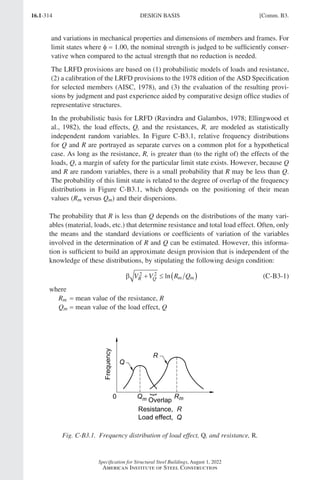
![16.1-315
Specification for Structural Steel Buildings, August 1, 2022
American Institute of Steel Construction
VQ = coefficient of variation of the load effect, Q
VR = coefficient of variation of the resistance, R
β = reliability index
For structural elements and the usual loading, Rm, Qm, and the coefficients of varia-
tion, VR and VQ, can be estimated, so a calculation of
β =
( )
+
1
2 2
n R Q
V V
m m
R Q
(C-B3-2)
will give a comparative measure of reliability of a structure or component. Exten-
sions to the determination of β in Equation C-B3-2 to accommodate additional
probabilistic information and more complex design situations are described in
Ellingwood et al. (1982) and have been used in the development of the recommended
load combinations in ASCE/SEI 7.
The original studies that determined the statistical properties (mean values and coef-
ficients of variation) for the basic material properties and for steel beams, columns,
composite beams, plate girders, beam-columns, and connection elements that were
used to develop the LRFD provisions are presented in a series of eight articles in the
September 1978 issue of the Journal of the Structural Division (ASCE, 1978). The
corresponding load statistics are given in Galambos et al. (1982). Based on these sta-
tistics, the values of β inherent in the 1978 Specification for the Design, Fabrication,
and Erection of Structural Steel for Buildings (AISC, 1978) were evaluated under
different load combinations (live/dead, wind/dead, etc.) and for various tributary
areas for typical members (beams, columns, beam-columns, structural components,
etc.). As might be expected, there was a considerable variation in the range of
β-values. For example, compact rolled beams (flexure) and tension members (yield-
ing) had β-values that decreased from about 3.1 at L D = 0.50 to 2.4 at L D = 4.
This decrease is a result of ASD applying the same factor to dead load, which is
relatively predictable, and live load, which is more variable. For bolted or welded
connections, β was in the range of 4 to 5.
The variation in β that was inherent to ASD is reduced substantially in LRFD by
specifying several target β-values and selecting load and resistance factors to meet
these targets. The Committee on Specifications set the point at which LRFD is
calibrated to ASD at L D = 3.0 for braced compact beams in flexure and tension
members at yield. The resistance factor, φ, for these limit states is 0.90, and the
implied β is approximately 2.6 for members and 4.0 for connections. The larger
β-value for connections reflects the complexity in modeling their behavior, effects of
workmanship, and the benefit provided by additional strength. Limit states for other
members are handled similarly.
The databases on steel strength used in previous editions of the LRFD Specification
(AISC, 1986, 1993, 2000b) were based mainly on research conducted prior to 1970.
An important study of the material properties of structural shapes (Bartlett et al.,
2003) reflected changes in steel production methods and steel materials that had
occurred over the 15 years since the original study. This study indicated that the new
steel material characteristics did not warrant changes in the φ-values.
Comm. B3.] DESIGN BASIS
Part 16.1 Commentary A-E (295-369).indd 315
Part 16.1 Commentary A-E (295-369).indd 315 2023-01-23 6:59 PM
2023-01-23 6:59 PM](https://image.slidesharecdn.com/aisc360-22specificationforstructuralsteelbuildings-231108145904-1b416cfe/85/AISC-360-22-Specification-for-Structural-Steel-Buildings-pdf-383-320.jpg)
![16.1-317
Specification for Structural Steel Buildings, August 1, 2022
American Institute of Steel Construction
For design according to Section B3.2 (ASD)
R
D L D D D
n
Ω
= + = + =
3 4 (C-B3-4)
Rn = Ω(4D)
Equating Rn from the LRFD and ASD formulations and solving for Ω yields
Ω =
=
6 1
4
1 5
D
D
φ φ
. (C-B3-5)
Throughout this Specification, the values of Ω were obtained from the values of φ
by Equation C-B3-5.
Based on Equation C-B3-5, the relationship between available strengths for LRFD
and ASD is seen to be a constant of 1.5. However, that cannot be said for the rela-
tionship between required strengths for LRFD and ASD that are based on the load
combinations given in ASCE/SEI 7. Thus, the exact level of safety will vary between
LRFD and ASD. For the gravity load combinations given in Equations C-B3-3 and
C-B3-4, and the assumed L = 3D, ASD safety is equivalent to that for LRFD accord-
ing to Equation C-B3-5. An alternative way to present the relationship between
LRFD and ASD is to consider the ratio of the LRFD demand-to-capacity ratio
DCR R R
LRFD u n
=
( )
φ to the ASD demand-to-capacity ratio DCR R R
ASD a n
= ( )
[ ]
Ω
(Salmon et al., 2008). Thus,
DCR
DCR
R R
R R
LRFD
ASD
u n
a n
=
( )
φ
Ω
(C-B3-6)
Equation C-B3-6 can be understood to provide the LRFD evaluation of an ASD
design, with values below unity indicating that ASD is conservative with respect to
LRFD and values above unity indicating that ASD is unconservative with respect to
LRFD. With the parameters Ru = 1.2D + 1.6L, Ra = D + L, and Ω =1 5
. φ, Equation
C-B3-6 will provide ratios of DCRs ranging from 0.830 to 1.067. Values of L D 3
have a ratio below unity (indicating ASD is conservative compared to LRFD) and
values of L D 3 have a ratio above unity (indicating ASD is unconservative com-
pared to LRFD). The unconservative value of 1.067 is considered acceptable; such a
minor difference does not have a significant effect on reliability.
A much larger variation in the ratio of DCRs may be observed for the ASCE/SEI 7
wind and earthquake lateral load combinations. For example, for members in which
the ratio of the wind load effect to the dead load effect is high (W D 3), a situation
that may be assumed for the design of several elements in a lateral force-resisting
system such as diagonal braces and often the columns that support them, the ratio
of the DCRs ranged from 0.90 to as high as 1.36 depending on the significance of
second-order effects, which were varied from B2 = 1.0 to 1.5, and the live load-to-dead
load ratio, which was varied from L D = 0 5
to . The L D ratio was taken to apply
to both the element and, for determination of second-order effects, the structure as
a whole. With the exception of L D 0 2
. , all of the ratios of DCRs exceeded unity,
with values exceeding 1.20 for the majority of the range of B2 and L D considered.
Comm. B3.] DESIGN BASIS
Part 16.1 Commentary A-E (295-369).indd 317
Part 16.1 Commentary A-E (295-369).indd 317 2023-01-26 1:19 PM
2023-01-26 1:19 PM](https://image.slidesharecdn.com/aisc360-22specificationforstructuralsteelbuildings-231108145904-1b416cfe/85/AISC-360-22-Specification-for-Structural-Steel-Buildings-pdf-385-320.jpg)
![16.1-319
Specification for Structural Steel Buildings, August 1, 2022
American Institute of Steel Construction
In certain cases, the deformation of the connection elements affects the way the
structure resists load and hence the connections must be included in the analysis of
the structural system. These connections are referred to as partially restrained (PR)
moment connections. For structures with PR connections, the connection flexibility
must be estimated and included in the structural analysis, as described in the fol-
lowing sections. Once the analysis is complete, the load effects and deformations
computed for the connection can be used to check the adequacy of the connecting
elements.
For simple and FR connections, the connection proportions are established after the
final analysis of the structural design is completed, thereby greatly simplifying the
design cycle. In contrast, the design of PR connections (like member selection) is
inherently iterative because one must assume values of the connection proportions in
order to establish the force-deformation characteristics of the connection needed to
perform the structural analysis. The life-cycle performance characteristics must also
be considered. The adequacy of the assumed proportions of the connection elements
can be verified once the outcome of the structural analysis is known. If the con-
nection elements are inadequate, then the values must be revised and the structural
analysis repeated. The potential benefits of using PR connections for various types of
framing systems are discussed in the literature referenced in the following.
Connection Classification. The basic assumption made in classifying connections
is that the most important behavioral characteristics of the connection can be mod-
eled by a moment-rotation, M-θ, curve. Figure C-B3.2 shows a typical M-θ curve.
Implicit in the moment-rotation curve is the definition of the connection as being a
region of the column and beam along with the connecting elements. The connection
response is defined this way because the rotation of the member in a physical test
is generally measured over a length that incorporates the contributions of not only
the connecting elements, but also the ends of the members being connected and the
column panel zone.
Fig. C-B3.2. Definition of stiffness, strength, and ductility characteristics of the
moment-rotation response of a partially restrained connection.
Comm. B3.] DESIGN BASIS
Part 16.1 Commentary A-E (295-369).indd 319
Part 16.1 Commentary A-E (295-369).indd 319 2023-01-23 6:59 PM
2023-01-23 6:59 PM](https://image.slidesharecdn.com/aisc360-22specificationforstructuralsteelbuildings-231108145904-1b416cfe/85/AISC-360-22-Specification-for-Structural-Steel-Buildings-pdf-387-320.jpg)
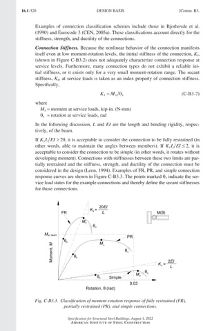
![16.1-321
Specification for Structural Steel Buildings, August 1, 2022
American Institute of Steel Construction
Connection Strength. The strength of a connection is the maximum moment that it
is capable of carrying, Mn, as shown in Figure C-B3.2. The strength of a connection
can be determined on the basis of an ultimate limit-state model of the connection,
or from physical tests. If the moment-rotation response does not exhibit a peak load
then the strength can be taken as the moment at a rotation of 0.02 rad (Hsieh and
Deierlein, 1991; Leon et al., 1996).
It is also useful to define a lower limit on strength below which the connection may
be treated as a simple connection. Connections that transmit less than 20% of the
fully plastic moment of the beam at a rotation of 0.02 rad may be considered to have
no flexural strength for design. However, it should be recognized that the aggregate
strength of many weak connections can be important when compared to that of a few
strong connections (FEMA, 1997).
In Figure C-B3.3, the points marked Mn indicate the maximum strength states of the
example connections. The points marked θu indicate the maximum rotation states
of the example connections. Note that it is possible for an FR connection to have a
strength less than the strength of the beam. It is also possible for a PR connection to
have a strength greater than the strength of the beam. The strength of the connection
must be adequate to resist the moment demands implied by the design loads.
Connection Ductility. If the connection strength substantially exceeds the fully
plastic moment strength of the beam, then the ductility of the structural system is
controlled by the beam and the connection can be considered elastic. If the connec-
tion strength only marginally exceeds the fully plastic moment strength of the beam,
then the connection may experience substantial inelastic deformation before the
beam reaches its full strength. If the beam strength exceeds the connection strength,
then deformations can concentrate in the connection. The ductility required of a
connection will depend upon the particular application. For example, the ductility
requirement for a braced frame in a nonseismic area will generally be less than the
ductility required in a high seismic area. The rotation ductility requirements for seis-
mic design depend upon the structural system (AISC, 2022c).
In Figure C-B3.2, the rotation capacity, θu, can be defined as the value of the connec-
tion rotation at the point where either (a) the resisting strength of the connection has
dropped to 0.8Mn or (b) the connection has deformed beyond 0.03 rad. This second
criterion is intended to apply to connections where there is no loss in strength until
very large rotations occur. It is not prudent to rely on these large rotations in design.
The available rotation capacity, θu, should be compared with the rotation required
at the strength limit state, as determined by an analysis that takes into account the
nonlinear behavior of the connection. (Note that for design by ASD, the rotation
required at the strength limit state should be assessed using analyses conducted at 1.6
times the ASD load combinations.) In the absence of an accurate analysis, a rotation
capacity of 0.03 rad is considered adequate. This rotation is equal to the minimum
beam-to-column connection capacity as specified in the seismic provisions for spe-
cial moment frames (AISC, 2022c). Many types of PR connections, such as top- and
seat-angle connections, meet this criterion.
Comm. B3.] DESIGN BASIS
Part 16.1 Commentary A-E (295-369).indd 321
Part 16.1 Commentary A-E (295-369).indd 321 2023-01-23 6:59 PM
2023-01-23 6:59 PM](https://image.slidesharecdn.com/aisc360-22specificationforstructuralsteelbuildings-231108145904-1b416cfe/85/AISC-360-22-Specification-for-Structural-Steel-Buildings-pdf-389-320.jpg)
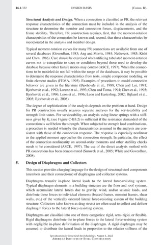
![16.1-323
Specification for Structural Steel Buildings, August 1, 2022
American Institute of Steel Construction
individual elements of the lateral force-resisting system. A semi-rigid diaphragm
distributes the lateral loads in proportion to the in-plane stiffness of the diaphragm
and the relative stiffness of the individual elements of the lateral force-resisting sys-
tem. With a flexible diaphragm, the in-plane stiffness of the diaphragm is negligible
compared to the stiffness of the lateral force-resisting system and, therefore, the
distribution of lateral forces is independent of the relative stiffness of the individual
elements of the lateral force-resisting system. In this case, the distribution of lateral
forces may be computed in a manner analogous to a series of simple beams spanning
between the lateral force-resisting system elements.
Diaphragms should be designed for the shear, moment, and axial forces resulting
from the design loads. The diaphragm response may be considered analogous to a
deep beam where the flanges (often referred to as chords of the diaphragm) develop
tension and compression forces, and the web resists the shear. The component ele-
ments of the diaphragm need to have strength and deformation capacity consistent
with the assumptions and intended behavior.
6. Design of Anchorages to Concrete
This section provides the charging language for Chapter I and Chapter J on design
of anchorages to concrete.
7. Design for Stability
This section provides the charging language for Chapter C on design for stability.
8. Design for Serviceability
This section provides the charging language for Chapter L on design for service-
ability.
9. Design for Structural Integrity
This section provides the minimum connection design criteria for satisfying struc-
tural integrity requirements where required by the applicable building code. Section
1616 of the International Building Code (ICC, 2021) assigns structural integrity
requirements to high-rise buildings in risk category III or IV, which means that the
number of buildings to which this requirement currently applies is limited.
Evaluation of built structures that have been subjected to extraordinary events
indicates that structures that have a higher level of connectivity perform better than
those that do not. The intent of the integrity requirements is to achieve this improved
connectivity by limiting the possibility of a connection failure when it is subjected to
unanticipated tension forces. The forces can result from a wide range of events such
as cool-down after a fire, failure of adjacent structural members, and blast or impact
loads on columns. The Specification integrity checks are similar in principle to those
defined in other model codes and international codes that have provided good his-
torical performance (Geschwindner and Gustafson, 2010). The fundamental aspect
of the integrity requirement is that it is a connection design requirement only and is
not a design force applied to any part of the structure other than the connection itself.
In addition, the forces determined for the integrity check are not to be combined
with any other forces and the integrity connection design check is to be conducted
Comm. B3.] DESIGN BASIS
Part 16.1 Commentary A-E (295-369).indd 323
Part 16.1 Commentary A-E (295-369).indd 323 2023-01-23 6:59 PM
2023-01-23 6:59 PM](https://image.slidesharecdn.com/aisc360-22specificationforstructuralsteelbuildings-231108145904-1b416cfe/85/AISC-360-22-Specification-for-Structural-Steel-Buildings-pdf-391-320.jpg)
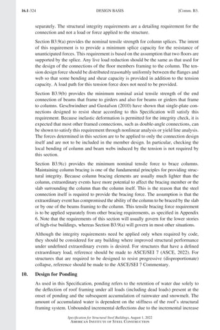
![16.1-325
Specification for Structural Steel Buildings, August 1, 2022
American Institute of Steel Construction
in retained water can result in the collapse of the roof. The problem becomes cata-
strophic when more water causes more deflection, resulting in a greater opportunity
for more water to accumulate until the roof collapses.
The Specification requires that design for ponding be considered if water is
impounded on the roof, irrespective of roof slope. Camber and deflections due to
loads acting concurrently with rain loads must be considered in establishing the
initial conditions.
Determination of ponding stability is typically done by structural analysis where
the rain loads are increased by the incremental deflections of the structural framing
system to the accumulated rainwater, assuming the primary roof drains are blocked.
Previous editions of this Specification detailed provisions and design aids for deter-
mining ponding stability and strength in Appendix 2. These methods were applicable
to a limited class of roof configurations and were inconsistent with the remainder
of the Specification. For these reasons, they have been removed, and methods and
discussions for analyzing and designing for ponding stability may be found in SJI
Technical Digest 3, Structural Design of Steel Joist Roofs to Resist Ponding Loads
(Fisher and Denavit, 2018).
11. Design for Fatigue
Fatigue is a limit state that must be considered like other limit states but only in
specific applications. There are situations where fatigue may be a controlling limit
state, such as in crane runways and their supports. Experience has shown that the
cyclic loading associated with the effects of wind or snow loading on typical build-
ing systems does not cause fatigue because the number of high stress-range cycles is
typically low enough to preclude fatigue crack initiation.
Appendix 3 deals with high cycle, low stress-range fatigue; while seismic loading is
also cyclic, it involves low cycle, high stress-range fatigue, which is not considered
in Appendix 3. The effects of low cycle fatigue are implicitly considered in the
requirements of the AISC Seismic Provisions for Structural Steel Buildings (AISC,
2022c), and the AISC Prequalified Connections for Special and Intermediate Steel
Moment Frames for Seismic Applications (AISC, 2022b).
12. Design for Fire Conditions
This section provides the charging language for Appendix 4 on structural design
for fire resistance. Both alternatives, (a) qualification testing and (b) analysis, are
deemed acceptable for providing fire resistance. Design by analysis is addressed in
Appendix 4, Sections 4.1 and 4.2. Qualification testing is addressed in Appendix 4,
Section 4.3, which includes relevant provisions reproduced from the International
Building Code (ICC, 2018), ASCE/SEI/SFPE Standard 29 (ASCE, 2005), ASTM
E119 (ASTM, 2020d), and similar documents.
13. Design for Corrosion Effects
Steel members may deteriorate in some service environments. This deterioration
may appear either as external corrosion, which would be visible upon inspection,
Comm. B3.] DESIGN BASIS
Part 16.1 Commentary A-E (295-369).indd 325
Part 16.1 Commentary A-E (295-369).indd 325 2023-01-23 6:59 PM
2023-01-23 6:59 PM](https://image.slidesharecdn.com/aisc360-22specificationforstructuralsteelbuildings-231108145904-1b416cfe/85/AISC-360-22-Specification-for-Structural-Steel-Buildings-pdf-393-320.jpg)
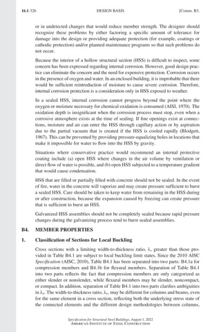
![16.1-327
Specification for Structural Steel Buildings, August 1, 2022
American Institute of Steel Construction
Chapter E and Appendix 1, and beams, Chapter F and Appendix 1. A comprehensive
review of the basis for the local buckling width-to-thickness limits of Table B4.1 is
presented by Schafer et al. (2022).
Limiting Width-to-Thickness Ratios for Compression Elements in Members
Subjected to Axial Compression. Compression members containing any elements
with width-to-thickness ratios greater than λr provided in Table B4.1a are desig-
nated as slender and are subject to the local buckling reductions detailed in Section
E7. Nonslender compression members (all elements having width-to-thickness ratio
≤ λr) are not subject to local buckling reductions.
Flanges of Built-Up I-Shaped Sections. In the 1993 Load and Resistance Factor
Design Specification for Structural Steel Buildings (AISC, 1993), for built-up
I-shaped sections under axial compression (Case 2 in Table B4.1a), modifications
were made to the flange local buckling criterion to include web-flange interac-
tion. The kc in the λr limit is the same as that used for flexural members. Theory
indicates that the web-flange interaction in axial compression is at least as severe
as in flexure. Rolled shapes are excluded from this provision because there are no
standard sections with proportions where the interaction would occur at commonly
available yield stresses. In built-up sections where the interaction causes a reduction
in the flange local buckling strength, it is likely that the web is also a thin stiffened
element. The kc factor accounts for the interaction of flange and web local buckling
demonstrated in experiments reported in Johnson (1985). The maximum limit of
0.76 corresponds to F E
cr = 0 69 2
. λ , which was used as the local buckling strength in
earlier editions of both the ASD and LRFD Specifications. An h tw = 27 5
. is required
to reach kc = 0.76. Fully fixed restraint for an unstiffened compression element cor-
responds to kc = 1.3 while zero restraint gives kc = 0.42. Because of web-flange
interactions, it is possible to get kc 0.42 from the kc formula. If h t E F
w y
5 70
. ,
use h t E F
w y
= 5 70
. in the kc equation, which corresponds to the 0.35 limit.
Rectangular HSS in Compression. The limits for rectangular HSS walls in uniform
compression (Case 6 in Table B4.1a) have been used in AISC Specifications since
1969 (AISC, 1969). They are based on Winter (1968), where adjacent stiffened
compression elements in box sections of uniform thickness were observed to provide
negligible torsional restraint for one another along their corner edges.
Round HSS in Compression. The λr limit for round HSS in compression (Case 9 in
Table B4.1a) was first used in the 1978 Specification for the Design, Fabrication,
and Erection of Structural Steel for Buildings (AISC, 1978). It was recommended in
Schilling (1965) based upon research reported in Winter (1968). Excluding the use
of round HSS with D t E Fy
0 45
. was also recommended in Schilling (1965). This
is implied in Sections E7 and F8 where no criteria are given for round HSS with D t
greater than this limit.
Limiting Width-to-Thickness Ratios for Compression Elements in Members Sub-
jected to Flexure. Flexural members containing compression elements, all with
width-to-thickness ratios less than or equal to λp as provided in Table B4.1b, are desig-
nated as compact. Compact sections are capable of developing a fully plastic stress
Comm. B4.] MEMBER PROPERTIES
Part 16.1 Commentary A-E (295-369).indd 327
Part 16.1 Commentary A-E (295-369).indd 327 2023-01-23 6:59 PM
2023-01-23 6:59 PM](https://image.slidesharecdn.com/aisc360-22specificationforstructuralsteelbuildings-231108145904-1b416cfe/85/AISC-360-22-Specification-for-Structural-Steel-Buildings-pdf-395-320.jpg)
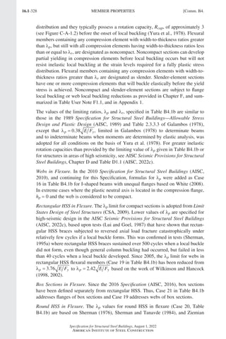
![16.1-329
Specification for Structural Steel Buildings, August 1, 2022
American Institute of Steel Construction
(2010). Beyond this, the local buckling strength decreases rapidly, making it imprac-
tical to use these sections in building construction.
Limiting Width-to-Thickness Ratios Where the Web and Flange are not Continu-
ously Attached. The Specification does not explicitly provide requirements for cases
where the cross-section elements are not continuously attached; this is due to the fact
that the buckling occurs over a short length and it is generally not practical to provide
less than continuous connection and still limit local buckling. Of course, a stiffened
element with one longitudinal edge intermittently connected may be conservatively
considered as an unstiffened element for the purposes of determining limiting width-
to-thickness ratios.
If an intermittent connection is to provide restraint similar to a continuous connec-
tion, it must provide adequate stiffness and strength at a spacing within the local
buckling half-wavelength of the cross-section element, in other words, at a spacing
less than approximately one-half the width-to-thickness ratio from Table B4.1 mul-
tiplied times the thickness. In general, width-to-thickness ratios similar to those in
Table B4.1 can be derived if the local buckling stress, Fcr, is accurately known. In
classic form, the local buckling stress is expressed as
F k
E t
b
cr =
−
( )
π
ν
2
2
2
12 1
(C-B4-1)
and is, therefore, a function of the material properties, dimensions, loading, and
boundary conditions as reflected through the plate buckling coefficient, k; see
Ziemian (2010). As detailed in Seif and Schafer (2010), if Fcr is known, then the lim-
iting width-to-thickness ratio, λr, from Table B4.1 is the b t such that F F
y cr = 0 7
.
for elements in compression and = 1.0 for elements in flexure. The limiting width-
to-thickness ratio, λp, from Table B4.1b is the b t such that F F
y cr = 0 46
. for
unstiffened elements and = 0.58 for stiffened elements. Thus, if the engineer can
approximate k, or perform a local buckling analysis consistent with the intermittent
connections for finding Fcr, then a limiting width-to-thickness ratio may be approxi-
mated. For an intermittently connected plate, AISI (2016) uses the approximation
of a pin-ended column of length equal to the connector spacing for determining Fcr.
For complex connection conditions, the provisions of Appendix 1 may provide an
alternative path for Specification-compliant design.
2. Design Wall Thickness for HSS
ASTM A500/A500M tolerances allow for a wall thickness that is not greater than
±10% of the nominal value. Because the plate and strip from which these HSS are
made are produced to a much smaller thickness tolerance, manufacturers in the
United States consistently produce these HSS with a wall thickness that is near the
lower-bound wall thickness limit. Consequently, AISC and the Steel Tube Institute
of North America (STI) recommend that 0.93 times the nominal wall thickness be
used for calculations involving engineering design properties of these HSS. This
results in a weight (mass) variation that is similar to that found in other structural
shapes. The design wall thickness and section properties based upon this reduced
thickness have been tabulated in AISC and STI publications since 1997.
Comm. B4.] MEMBER PROPERTIES
Part 16.1 Commentary A-E (295-369).indd 329
Part 16.1 Commentary A-E (295-369).indd 329 2023-01-23 6:59 PM
2023-01-23 6:59 PM](https://image.slidesharecdn.com/aisc360-22specificationforstructuralsteelbuildings-231108145904-1b416cfe/85/AISC-360-22-Specification-for-Structural-Steel-Buildings-pdf-397-320.jpg)
![16.1-331
Specification for Structural Steel Buildings, August 1, 2022
American Institute of Steel Construction
B7. EVALUATION OF EXISTING STRUCTURES
Section B7 provides the charging language for Appendix 5 on the evaluation of
existing structures.
B8. DIMENSIONAL TOLERANCES
This new section replaces Section M2.7, Dimensional Tolerances, in the 2016 AISC
Specification (AISC, 2016).
Dimensional tolerances (and production methods) are used to limit the magnitude of
geometric imperfections present in members and structures. In some instances there
is a direct relationship between the permitted dimensional tolerances of the member
or structure and the design provisions provided in this Specification. Geometric
imperfections have the most significant effect relative to the stability of the members
and structures. Evaluation of members and structures outside the assumed tolerances
falls outside the scope of this Specification and should be based on tests or analysis,
subject to the approval of the authority having jurisdiction.
There are a number of conditions that could result in geometric imperfections greater
than those assumed in the Specification being present in structural steel elements.
•
Engineers sometimes elect to employ materials that are not approved for use. In
such cases, the tolerances imposed by the standards for the chosen material may
exceed those permitted by comparable ASTM standards or no tolerances may be
enforced at all. Engineers must therefore either specify tighter tolerances consis-
tent with those assumed in the Specification or must account for the larger possible
tolerances in their designs,
• The AISC Code Standard Practice for Steel Buildings and Bridges (AISC, 2022a),
hereafter referred to as the Code of Standard Practice does not address every pos-
sible variation that could be encountered in practice. When a tolerance that is not
specified in the Code of Standard Practice is required so that the fabricated and
erected structural steel satisfy the design intent, the tolerance should be specified
in the contract documents. In some instances, it may be impractical to satisfy
tolerances comparable to those provided in the Code of Standard Practice or the
ASTM standards. In such cases, engineers must account for the larger permitted
tolerances in their designs,
•
For various reasons, structural steel elements are sometimes unintentionally pro-
vided out-of-tolerance. In some instances, the problem may be discovered at a
point where repair of the element is impractical or unsafe. In such cases, engineers
must account for the larger permitted tolerances in their designs and reinforcement
of the member may be an option.
The classification of sections for local buckling in Section B4.1 assumes tolerances
and production methods inherent in the ASTM standards approved for use under
this Specification in Section A3.1a. The limiting width-to-thickness ratios, λr and λp,
may have to be adjusted if larger geometric imperfections exist. Chapter C permits
the use of any rational method of design for stability as long as the listed effects are
considered. Geometric imperfections is one of the effects that must be considered.
The effect of geometric imperfections larger than those permitted in the ASTM
Comm. B8.] DIMENSIONAL TOLERANCES
Part 16.1 Commentary A-E (295-369).indd 331
Part 16.1 Commentary A-E (295-369).indd 331 2023-01-26 11:21 AM
2023-01-26 11:21 AM](https://image.slidesharecdn.com/aisc360-22specificationforstructuralsteelbuildings-231108145904-1b416cfe/85/AISC-360-22-Specification-for-Structural-Steel-Buildings-pdf-399-320.jpg)
![16.1-334
Specification for Structural Steel Buildings, August 1, 2022
American Institute of Steel Construction
TABLE C-C1.1
Comparison of Basic Stability Requirements with
Specific Provisions
Basic Requirement in Section C1
Provision in
Direct Analysis
Method
(DM)
Provision in
Effective Length
Method
(ELM)
(1) Consider all deformations C2.1(a). Consider
all deformations
Same as DM
(by reference to C2.1)
(2)
Consider second-order effects (both P-∆ and
P-δ)
C2.1(b). Consider
second-order effects
(P-∆ and P-δ)[b]
Same as DM
(by reference to C2.1)
(3)
Consider geometric
imperfections
This includes joint-
position imperfections[a]
(which affect structure
response) and member
imperfections (which
affect structure
response and member
strength).
Effect of system
imperfections on
structure response
C2.2a. Direct
modeling or
C2.2b. Notional loads
Same as DM,
second option only
(by reference to C2.2b)
Effect of member
imperfections on
structure response
Included in the
stiffness reduction
specified in C2.3
All these effects are
considered by using
Lc = KL from a
sidesway buckling
analysis in the
member strength check.
Note that the differences
between DM and ELM
are as follows:
•
DM uses reduced
stiffness in the
analysis and Lc = L
in the member
strength check.
•
ELM uses full stiffness
in the analysis and
Lc = KL from sidesway
buckling analysis in
the member strength
check.
Effect of member
imperfections on
member strength
Included in member
strength formulas,
with Lc = L
(4)
Consider stiffness
reduction due to
inelasticity
This affects structure
response and member
strength.
Effect of stiffness
reduction on
structure response
Included in the
stiffness reduction
specified in C2.3
Effect of stiffness
reduction on member
strength
Included in member
strength formulas,
with Lc = L
(5)
Consider uncertainty in
strength and stiffness
This affects structure
response and member
strength.
Effect of stiffness/
strength uncertainty
on structure response
Included in the
stiffness reduction
specified in C2.3
Effect of stiffness/
strength uncertainty
on member strength
Included in member
strength formulas,
with Lc = L
[a]In typical building structures, the “joint-position imperfections” refers to column out-of-plumbness.
[b]
Second-order effects may be considered either by a computational P-∆ and P-δ analysis or by the approxi-
mate method (using B1 and B2 multipliers) specified in Appendix 8.
Section 7.3) is not included in Table C-C1.1 because it addresses these requirements
in an indirect manner using a mathematical manipulation of the direct analysis
method. The additional lateral load required in Appendix 7, Section 7.3.2(a), is
calibrated to achieve roughly the same result as the collective effects of notional
loads required in Section C2.2b, P-∆ effects required in Section C2.1(b), and the
stiffness reduction required in Section C2.3. Additionally, a B1 multiplier addresses
P-δ effects as defined in Appendix 8, Section 8.1.2.
In the 2010 AISC Specification (AISC, 2010), uncertainties in stiffness and strength
was added to the list of effects that should be considered when designing for stability.
GENERAL STABILITY REQUIREMENTS [Comm. C1.
Part 16.1 Commentary A-E (295-369).indd 334
Part 16.1 Commentary A-E (295-369).indd 334 2023-01-23 6:59 PM
2023-01-23 6:59 PM](https://image.slidesharecdn.com/aisc360-22specificationforstructuralsteelbuildings-231108145904-1b416cfe/85/AISC-360-22-Specification-for-Structural-Steel-Buildings-pdf-402-320.jpg)
![16.1-335
Specification for Structural Steel Buildings, August 1, 2022
American Institute of Steel Construction
Although all methods detailed in this Specification, including the direct analysis
method, the effective length method, and the first-order elastic method, satisfy this
requirement, the effect is listed so that it is clear that it is to be included, along with
the original four other effects, when any other rational method of designing for sta-
bility is employed.
C2. CALCULATION OF REQUIRED STRENGTHS
Analysis to determine required strengths in accordance with this section and the
assessment of member and connection available strengths in accordance with Section
C3 form the basis of the direct analysis method of design for stability. This method
is useful for the stability design of all structural steel systems, including moment
frames, braced frames, shear walls, and combinations of these and similar systems
(AISC-SSRC, 2003a). While the precise formulation of this method is unique to the
Specification, some of its features are similar to those found in other major design
specifications around the world, including the Eurocodes, the Australian standard,
the Canadian standard, and ACI 318 (ACI, 2019).
The direct analysis method allows a more accurate determination of the load effects
in the structure through the inclusion of the effects of geometric imperfections and
stiffness reductions directly within the structural analysis. This also allows the use
of K =1 0
. in calculating the in-plane column strength, Pc, within the beam-column
interaction equations of Chapter H. This is a significant simplification in the design
of steel moment frames and combined systems. Verification studies for the direct
analysis method are provided by Deierlein et al. (2002), Maleck and White (2003),
and Martinez-Garcia and Ziemian (2006).
1. General Analysis Requirements
Deformations to be Considered in the Analysis. It is required that the analysis
consider flexural, shear, and axial deformations, and all other component and con-
nection deformations that contribute to the displacement of the structure. However,
it is important to note that “consider” is not synonymous with “include,” and some
deformations can be neglected after rational consideration of their likely effect. For
example, the in-plane deformation of a concrete-on-steel deck floor diaphragm in an
office building usually can be neglected, but that of a cold-formed steel roof deck
in a large warehouse with widely spaced lateral force-resisting elements usually
cannot. As another example, shear deformations in beams and columns in a low-
rise moment frame usually can be neglected, but this may not be true in a high-rise
framed-tube system with relatively deep members and short spans. For such frames,
the use of rigid offsets to account for member depths may significantly overestimate
frame stiffness and consequently underestimate second-order effects due to high
shear stresses within the panel zone of the connections. For example, Charney and
Johnson (1986) found that for the range of columns and beam sizes they studied, the
deflections of a subassembly modeled using centerline dimensions could vary from
an overestimation of 23% to an underestimation of 20% when compared to a finite
element model. Charney and Johnson conclude that analysis based on centerline
dimensions may either underestimate or overestimate drift, with results depending
on the span of the girder and on the web thickness of the column.
Comm. C2.] CALCULATION OF REQUIRED STRENGTHS
Part 16.1 Commentary A-E (295-369).indd 335
Part 16.1 Commentary A-E (295-369).indd 335 2023-01-23 6:59 PM
2023-01-23 6:59 PM](https://image.slidesharecdn.com/aisc360-22specificationforstructuralsteelbuildings-231108145904-1b416cfe/85/AISC-360-22-Specification-for-Structural-Steel-Buildings-pdf-403-320.jpg)
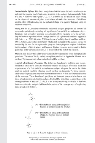
![16.1-337
Specification for Structural Steel Buildings, August 1, 2022
American Institute of Steel Construction
The benchmark problem descriptions and solutions are shown in Figures C-C2.2
and C-C2.3. Proportional loading is assumed and axial, flexural, and shear deforma-
tions are included. Case 1 is a simply supported beam-column subjected to an axial
load concurrent with a uniformly distributed transverse load between supports. This
problem contains only P-δ effects because there is no translation of one end of the
member relative to the other. Case 2 is a fixed-base cantilevered beam-column sub-
jected to an axial load concurrent with a lateral load at its top. This problem contains
both P-∆ and P-δ effects. In confirming the accuracy of the analysis method, both
moments and deflections should be checked at the locations shown for the various
levels of axial load on the member and in all cases should agree within 3% and 5%,
respectively.
P
28.0
ft
(8.53
m)
Major-axis bending
W14´48 (W360´72)
E = 29,000 ksi (200 000 MPa)
0.200
kip/ft
(2.92
kN/m)
Axial Force, P (kips) 0 150 300 450
235 270 316 380
[235] [269] [313] [375]
Mmid (kip-in.)
Dmid (in.)
0.202 0.230 0.269 0.322
[0.197] [0.224] [0.261] [0.311]
Axial Force, P´10 (N) 0 667 1,330 2,000
26.6 30.5 35.7 42.9
[26.6] [30.4] [35.4] [42.4]
Mmid´10 (N-mm)
Dmid (mm)
5.13 5.84 6.83 8.18
[5.00] [5.69] [6.63] [7.90]
Analyses include axial, flexural, and shear deformations.
[Values in brackets] exclude shear deformations.
-3
-6
Fig. C-C2.2. Benchmark problem Case 1.
Fig. C-C2.3. Benchmark problem Case 2.
Comm. C2.] CALCULATION OF REQUIRED STRENGTHS
Part 16.1 Commentary A-E (295-369).indd 337
Part 16.1 Commentary A-E (295-369).indd 337 2023-01-23 6:59 PM
2023-01-23 6:59 PM](https://image.slidesharecdn.com/aisc360-22specificationforstructuralsteelbuildings-231108145904-1b416cfe/85/AISC-360-22-Specification-for-Structural-Steel-Buildings-pdf-405-320.jpg)
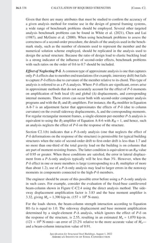
![16.1-339
Specification for Structural Steel Buildings, August 1, 2022
American Institute of Steel Construction
P-δ effects can be captured in some (but not all) P-∆-only analysis methods by subdi-
viding the members into multiple elements. For this example, three equal-length P-∆
analysis elements are required to reduce the errors in the second-order base moment
and sidesway displacement to less than 3% and 5%, respectively.
It should be noted that, in this case, the unconservative error that results from ignor-
ing the effect of P-δ on the response of the structure is removed through the use of
Equation A-8-8. For the loads shown in Figure C-C2.4, Equations A-8-6 and A-8-7
with RM = 0 85
. give a B2 amplifier of 3.52. This corresponds to Mu = 1,480 kip-in.
(170 × 106 N-mm) in the preceding example; approximately 6% over that determined
from a computational second-order analysis that includes both P-∆ and P-δ effects.
For sway columns with nominally simply supported base conditions, the errors in the
second-order internal moment and in the second-order displacements from a P-∆-only
analysis are generally smaller than 3% and 5%, respectively, when αP P
r eL ≤ 0 05
. ,
where
a = 1.0 (LRFD)
=
1.6 (ASD)
Pr = required axial force, ASD or LRFD, kips (N)
PeL = π2 2
EI L if the analysis uses nominal stiffness, kips (N)
=
0 8 2 2
. τ π
b EI L if the analysis uses a flexural stiffness reduction of 0.8τb,
kips (N)
For sway columns with rotational restraint at both ends of at least 1 5
. EI L
( ) if the
analysis uses nominal stiffness, or 1 5 0 8
. . τbEI L
( ) if the analysis uses a flexural
stiffness reduction of 0.8τb, the errors in the second-order internal moments and
displacements from a P-∆-only analysis are generally smaller than 3% and 5%, respec-
tively, when αP P
r eL ≤ 0 12
. .
0.50, 1.0
0.80 29,000 ksi 23,200 ksi (160 000 MPa)
2 1 8,920 ksi (61 500 MPa)
u y
P P
E
G E
2
6
Computational - and - analysis:
2.22 in. (56.4 mm)
1
,390 kip-in. 157 10 N-mm
8 9 1.00
nd
u
u c n u b n
P P
M
P P M M
1
6
1
1
- 6
1
-
Single-element - analysis:
0.580 in. (15 mm)
419 kip-in. (47.3 10 N-mm)
1
2.55
1
2.55 1,070 kip-in. (121 10 N-mm)
8 9 0.910
st
st
u st
P
u st
P
u c n u b n
P
M HL
P HL
M M
P P M M
Pu 440 kips (1.96106
N)
15.0
ft
(4.6
m)
Major-axis bending
Fully braced out-of-plane
W1060 (W25089)
Fy 50 ksi (345 MPa)
Include axial, flexural,
and shear deformations
H Hu Ni
1.45 kips 0.002(440 kips)
2.33 kips (10 400 N)
Fig. C-C2.4. Illustration of potential errors associated with
the use of a single-element-per-member P-∆ analysis.
Comm. C2.] CALCULATION OF REQUIRED STRENGTHS
Part 16.1 Commentary A-E (295-369).indd 339
Part 16.1 Commentary A-E (295-369).indd 339 2023-01-23 6:59 PM
2023-01-23 6:59 PM](https://image.slidesharecdn.com/aisc360-22specificationforstructuralsteelbuildings-231108145904-1b416cfe/85/AISC-360-22-Specification-for-Structural-Steel-Buildings-pdf-407-320.jpg)
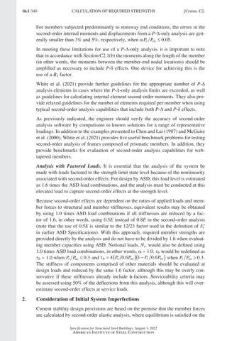
![16.1-341
Specification for Structural Steel Buildings, August 1, 2022
American Institute of Steel Construction
deformed geometry of the structure. Initial imperfections in the structure, such as
out-of-plumbness and material and fabrication tolerances, create additional destabi-
lizing effects.
In the development and calibration of the direct analysis method, initial geometric
imperfections were conservatively assumed equal to the maximum material, fabrica-
tion, and erection tolerances permitted in the AISC Code of Standard Practice for
Steel Buildings and Bridges (AISC, 2005a), which at the time included a member
out-of-straightness equal to L 1,000, where L is the member length between brace
or framing points, and a frame out-of-plumbness equal to H 500, where H is the
story height. Although the L 1,000 requirement on member out-of-straightness is no
longer specified in the current Code of Standard Practice (AISC, 2022a), it continues
to be specified in applicable ASTM material standards. The permitted out-of-plumb-
ness may be smaller in some cases, as specified in the Code of Standard Practice.
Initial imperfections may be accounted for in the direct analysis method through
direct modeling (Section C2.2a) or the inclusion of notional loads (Section C2.2b).
When second-order effects are such that the maximum sidesway amplification,
∆ ∆
2 1
nd order st order
- - or B2 ≤ 1.7 using the reduced elastic stiffness (or 1.5 using the
unreduced elastic stiffness) for all lateral load combinations, it is permitted to apply
notional loads only in gravity load-only combinations and not in combination with
other lateral loads. At this low range of sidesway amplification or B2, the errors in
internal forces caused by not applying the notional loads in combination with other
lateral loads are relatively small. When B2 is above this threshold, notional loads
must also be applied in combination with other lateral loads.
Appendix 1, Section 1.2, includes an extension to the direct analysis method that per-
mits direct modeling of initial imperfections along the lengths of members (member
imperfections) as well as at member ends (system imperfections). This extension
permits axially loaded members (columns and beam-columns according to Chapters
E and H, respectively) to be designed by employing a nominal compressive strength
that is taken as the cross-sectional strength; this is equivalent to the use of an effec-
tive member length, Lc = 0, when computing the nominal compressive strength, Pn,
of compression members.
The Specification requirements for consideration of initial imperfections are intended
to apply only to analyses for strength limit states. It is not necessary, in most cases, to
consider initial imperfections in analyses for serviceability conditions such as drift,
deflection, and vibration.
3. Adjustments to Stiffness
Partial yielding accentuated by residual stresses in members can produce a general
softening of the structure at the strength limit state that further creates additional
destabilizing effects. The direct analysis method is also calibrated against inelastic
distributed-plasticity analyses that account for the spread of plasticity through the
member cross section and along the member length. In these calibration studies,
residual stresses in wide-flange shapes were assumed to have a maximum value of
0.3Fy in compression at the flange tips, and a distribution matching the so-called
Comm. C2.] CALCULATION OF REQUIRED STRENGTHS
Part 16.1 Commentary A-E (295-369).indd 341
Part 16.1 Commentary A-E (295-369).indd 341 2023-01-23 6:59 PM
2023-01-23 6:59 PM](https://image.slidesharecdn.com/aisc360-22specificationforstructuralsteelbuildings-231108145904-1b416cfe/85/AISC-360-22-Specification-for-Structural-Steel-Buildings-pdf-409-320.jpg)
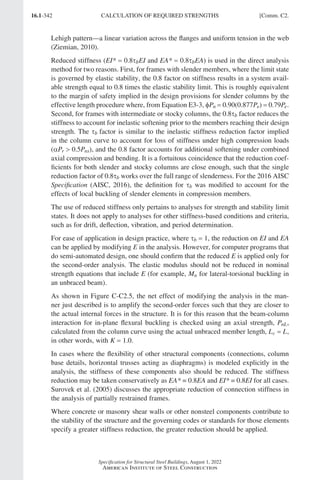
![16.1-343
Specification for Structural Steel Buildings, August 1, 2022
American Institute of Steel Construction
Comm. C3.] CALCULATION OF AVAILABLE STRENGTHS
C3. CALCULATION OF AVAILABLE STRENGTHS
Section C3 provides that when the analysis meets the requirements in Section C2,
the member provisions for available strength in Chapters D through I and connection
provisions in Chapters J and K complete the process of design by the direct analysis
method. The effective length for flexural buckling may be taken as the unbraced
length for all members in the strength checks.
Where beams and columns rely upon braces that are not part of the lateral force-
resisting system to define their unbraced length, the braces themselves must have
sufficient strength and stiffness to control member movement at the brace points
(see Appendix 6). Design requirements for braces that are part of the lateral force-
resisting system (that is, braces that are included within the analysis of the structure)
are included within Chapter C.
(a) Effective length method (PnKL is the nominal compressive strength used in
the effective length method; see Appendix 7)
(b) Direct analysis method (DM)
Fig. C-C2.5. Comparison of in-plane beam-column interaction checks for
(a) the effective length method and (b) the direct analysis method (DM).
Part 16.1 Commentary A-E (295-369).indd 343
Part 16.1 Commentary A-E (295-369).indd 343 2023-01-23 6:5](https://image.slidesharecdn.com/aisc360-22specificationforstructuralsteelbuildings-231108145904-1b416cfe/85/AISC-360-22-Specification-for-Structural-Steel-Buildings-pdf-411-320.jpg)