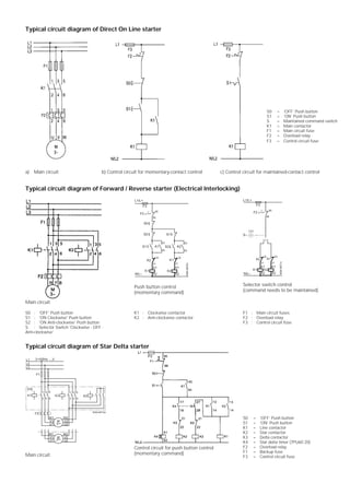
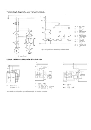
Typical circuit diagram of Direct On Line starter
a) Main circuit b) Control circuit for momentary-contact control c) Control circuit for maintained-contact control
Typical circuit diagram of Forward / Reverse starter (Electrical Interlocking)
Main circuit
L1/L+
S0
S1 K1
K1
N/L
NSK-6970c
F3
53
54
A1
A2
21
22
A1
21
22
K2
53
54
S2
S2 S1
F2
96
95
K2 K1
K2
A2
Push button control
(momentary command)
L1/L+
S
K1
N/L
NSK-6971c
F3
A1
A2
21
22
A1
21
22
F2
96
95
K2 K1
K2
A2
10 2
Selector switch control
(command needs to be maintained)
S0 : 'OFF' Push button
S1 : 'ON Clockwise' Push button
S2 : 'ON Anti-clockwise' Push button
S : Selector Switch 'Clockwise - OFF -
Anti-clockwise'
K1 : Clockwise contactor
K2 : Anti-clockwise contactor
F1 : Main circuit fuses
F2 : Overload relay
F3 : Control circuit fuse
Typical circuit diagram of Star Delta starter
Main circuit
Control circuit for push button control
(momentary command)
S0 = ‘OFF’ Push button
S1 = ‘ON’ Push button
K1 = Line contactor
K2 = Star contactor
K3 = Delta contactor
K4 = Star delta timer (7PU60 20)
F2 = Overload relay
F1 = Backup fuse
F3 = Control circuit fuse
S0 = ‘OFF’ Push button
S1 = ‘ON’ Push button
S = Maintained command switch
K1 = Main contactor
F1 = Main circuit fuse
F2 = Overload relay
F3 = Control circuit fuse
Typical circuit diagram for Auto Transformer starter
Internal connection diagram for DC coil circuits
K1 : Sizes 3 to 6,
3TF46 to 3TF51
K1 : Sizes 8 to 12
3TF52 to 3TF56
K2 : 3TF30 10 OB.. for 3TF54/55
3TF32 00-OB.. for 3TF56
K1 : Size 12
3TF57
K2 : 3TC44 17 4A..
The control circuits indicated by dotted lines are to be wired by customer.
a) Main Circuit
b) Auxiliary circuit for momentary-contact control
S0 = ‘OFF’ Push
button
S1 = ‘ON’ Push
button
K1 = Star contactor
K2 = Transformer
contactor
K3 = Main contactor
K5 = Contactor relay
(2NO + 2NC)
K4 = Time relay
(7PU6020)
F1 = Main circuit
fuses
F2 = Overload relay
F3 = Control circuit
fuse

3 phase electrical schematics

  • 1.
    Typical circuit diagramof Direct On Line starter a) Main circuit b) Control circuit for momentary-contact control c) Control circuit for maintained-contact control Typical circuit diagram of Forward / Reverse starter (Electrical Interlocking) Main circuit L1/L+ S0 S1 K1 K1 N/L NSK-6970c F3 53 54 A1 A2 21 22 A1 21 22 K2 53 54 S2 S2 S1 F2 96 95 K2 K1 K2 A2 Push button control (momentary command) L1/L+ S K1 N/L NSK-6971c F3 A1 A2 21 22 A1 21 22 F2 96 95 K2 K1 K2 A2 10 2 Selector switch control (command needs to be maintained) S0 : 'OFF' Push button S1 : 'ON Clockwise' Push button S2 : 'ON Anti-clockwise' Push button S : Selector Switch 'Clockwise - OFF - Anti-clockwise' K1 : Clockwise contactor K2 : Anti-clockwise contactor F1 : Main circuit fuses F2 : Overload relay F3 : Control circuit fuse Typical circuit diagram of Star Delta starter Main circuit Control circuit for push button control (momentary command) S0 = ‘OFF’ Push button S1 = ‘ON’ Push button K1 = Line contactor K2 = Star contactor K3 = Delta contactor K4 = Star delta timer (7PU60 20) F2 = Overload relay F1 = Backup fuse F3 = Control circuit fuse S0 = ‘OFF’ Push button S1 = ‘ON’ Push button S = Maintained command switch K1 = Main contactor F1 = Main circuit fuse F2 = Overload relay F3 = Control circuit fuse
  • 2.
    Typical circuit diagramfor Auto Transformer starter Internal connection diagram for DC coil circuits K1 : Sizes 3 to 6, 3TF46 to 3TF51 K1 : Sizes 8 to 12 3TF52 to 3TF56 K2 : 3TF30 10 OB.. for 3TF54/55 3TF32 00-OB.. for 3TF56 K1 : Size 12 3TF57 K2 : 3TC44 17 4A.. The control circuits indicated by dotted lines are to be wired by customer. a) Main Circuit b) Auxiliary circuit for momentary-contact control S0 = ‘OFF’ Push button S1 = ‘ON’ Push button K1 = Star contactor K2 = Transformer contactor K3 = Main contactor K5 = Contactor relay (2NO + 2NC) K4 = Time relay (7PU6020) F1 = Main circuit fuses F2 = Overload relay F3 = Control circuit fuse