
Recommended
More Related Content
What's hot
What's hot (20)
Similar to 3 bending stress-asgn
Similar to 3 bending stress-asgn (20)
Recently uploaded
Recently uploaded (20)
3 bending stress-asgn
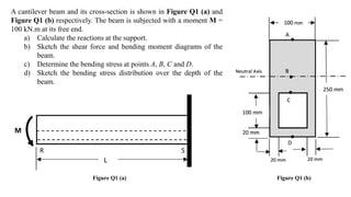
- 1. A cantilever beam and its cross-section is shown in Figure Q1 (a) and Figure Q1 (b) respectively. The beam is subjected with a moment M = 100 kN.m at its free end. a) Calculate the reactions at the support. b) Sketch the shear force and bending moment diagrams of the beam. c) Determine the bending stress at points A, B, C and D. d) Sketch the bending stress distribution over the depth of the beam. Figure Q1 (a) Figure Q1 (b) R S
- 2. R S Follow the +ve sign convention 0 0 y S F V Note: A –ve moment because the moment is bending the beam downward, and forms a SAD FACE. Equilibrium 2 VS MS V M + VM 0 0 100 . S S M M M M M kN m MM Pure moment, hence no shear force - a) Reactions at support
- 3. R S Shear Force Diagram 3 -100 Bending Moment Diagram V(kN) x(m) Zero Shear Force M(kN.m) x(m) -100 b) Shear Force and Bending Moment Diagrams
- 4. c) Bending stress 4 +y y is the distance measured from the neutral axis Hence, must calculate the location of neutral axis first for non-symmetric cross-section Note: For symmetric cross- section, the neutral axis is located at mid-height -y My I
- 5. Firstly, choose a reference point 5 Find the area and centroid of each section ref Note, for this case, it is (Aӯ)1 – (Aӯ)2 1 2 Sec Sign A (mm2) ӯ (mm) Aӯ (mm3) 1 + 100250 125 3.13106 2 - 60100 70 4.20105 ΣA 1.9104 ΣAӯ 2.71106 Centroid ӯ2 ӯ1 6 4 . 2.71 10 142.4 1.9 10 A y y mm A Note, for this case, it is A1 – A2
- 6. Moment of Inertia 6 Find the distance d between the centroid of each section and the neutral axis of the entire section ref 1 2 Sec Sign A (mm2) d (mm) Ad2 (mm4) 1 + 100250 17.4 7.57106 2 - 60100 72.4 3.15107 ӯ2 ӯ1 ӯ d1 d2 Sec Sign b (mm2) h (mm) I=bh3/12 (mm4) 1 + 100 250 1.3108 2 - 60 100 5106 Determine b and h. Subsequently, calculate I. 3 3 2 2 8 4 1 2 1.01 10 12 12 tot bh bh I Ad Ad mm
- 7. Bending stress at A 7 ӯ = 142.4 mm yA = 107.6mm Point A is located above the neutral axis. Hence, yA = +ve. 6 8 4 ( 100 10 . )(107.6 ) 1.01 10 106.2 A My I N mm mm mm MPa
- 8. Bending stress at B 8 ӯ Point B is located on the neutral axis. Hence, yB = 0. 0B
- 9. Bending stress at C 9 yC = -22.4 mm Point C is located below the neutral axis. Hence, yC = -ve. 6 8 4 ( 100 10 . )( 22.4 ) 1.01 10 22.1 C My I N mm mm mm MPa ӯ = 142.4 mm
- 10. Bending stress at D 10 yD = -ӯ = -142.4 mm Point D is located below the neutral axis. Hence, yD = – ve. 6 8 4 ( 100 10 . )( 142.4 ) 1.01 10 140.5 D My I N mm mm mm MPa
- 11. d) Stress distribution 11 Bending stress at point A is +ve. Bending stress at point D is - ve. Connect the two stresses with a straight line that passes through zero at neutral axis. -140.5 MPa 106.2 MPa
- 12. e) How to strengthen the beam? 12