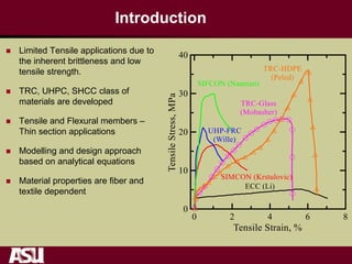
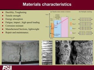
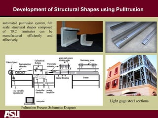
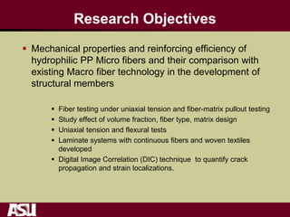
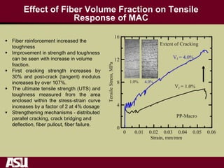
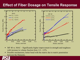
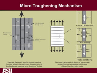
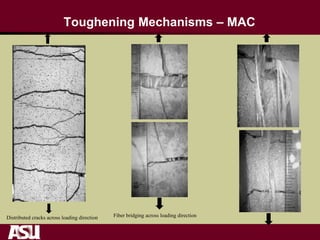
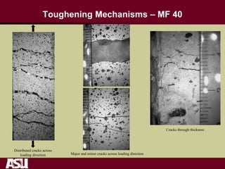
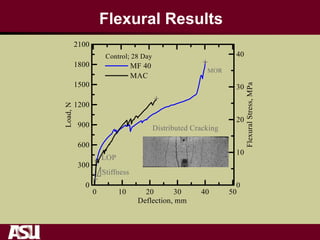
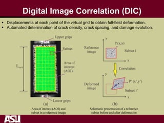
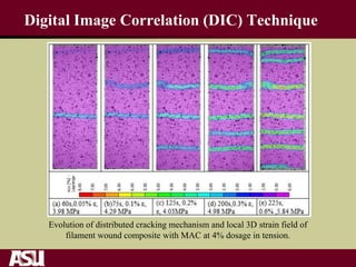
Mechanical Properties Of Unidirectional Polypropylene
Fiber Cement Composites
Vikram Dey, Jacob Bauchmoyer, Himai Mehere, Emmanuel
Attiogbe*, Barzin Mobasher
School of Sustainable Engineering and the Built Environment
Arizona State University , Tempe, AZ 85287-5306
*Senior Expert, Development Head, Innovation Cluster Technologies, BASF
BEFIB 2016, 9th Rilem International Symposium on Fiber Reinforced Concrete,
September, 2016, Vancouver, Canada
Introduction
 Limited Tensile applications due to
the inherent brittleness and low
tensile strength.
 TRC, UHPC, SHCC class of
materials are developed
 Tensile and Flexural members –
Thin section applications
 Modelling and design approach
based on analytical equations
 Material properties are fiber and
textile dependent
Materials characteristics
 Ductility, Toughening
 Tensile strength
 Energy absorption
 Fatigue, impact , high speed loading
 Corrosion resistant
 Manufactured Sections, lightweight
 Repair and maintenance.
500 m
20 m
(c)
200 m
(d)
(a)
500 m
(b)
Development of Structural Shapes using Pulltrusion
automated pultrusion system, full
scale structural shapes composed
of TRC laminates can be
manufactured efficiently and
effectively.
Pultrusion Process Schematic Diagram
Light gage steel sections
Pultruded Full Size TRC Structural Shapes
Cross section of pultruded shapes with TRC laminates
Research Objectives
 Mechanical properties and reinforcing efficiency of
hydrophilic PP Micro fibers and their comparison with
existing Macro fiber technology in the development of
structural members
 Fiber testing under uniaxial tension and fiber-matrix pullout testing
 Study effect of volume fraction, fiber type, matrix design
 Uniaxial tension and flexural tests
 Laminate systems with continuous fibers and woven textiles
developed
 Digital Image Correlation (DIC) technique to quantify crack
propagation and strain localizations.
Filament Winding Continuous manufacturing at ASU
Hardware consists of:
 National Instruments (NI) integrated system
 Gearbox
 Power Supply units
 4-axis stepper motion controller
 4-axis motion interface
 NI Motion driver software
 Controlled casting process
Impregnation
Chamber
Laminate Mold
Motion Controller
Wetting Tank(a)
Direction of
Fiber
Linear Guide
Stepper Motor #1
Power Supply Units
Stepper Motor #2
with gear box
Chain and Sprocket
Assembly
Fiber
Roving
Feed
Section
Guidance
Take-up
Section
Mechanical Components
Yarn/Fiber Testing
MAC MF 40
Loading Rate (mm/min) 0.4 2.5
Gage Length (mm) 25 25
Effective Yarn Dia. (mm) 0.82 0.89
Tensile Strength (MPa) 311 (+/-38) 492 (+/-65)
Elastic Modulus (MPa) 4499 (+/-351) 1601 (+/-117)
Toughness (MPa) 34 (+/-12) MPa 5058 (+/-1748)
2) Microfiber – MF 40
Fibrillated multi filament micro-fiber
500 filaments of 40 microns per yarn
1) Macro-synthetic fiber – MAC
Chemically enhanced macro-fiber
Fiber Pullout Test - Experimental setup
Load Cell
Pullout
Specimen
Effect of Fiber Embedded Length Macro PP vs. Steel
Pullout energy as the area
enclosed by load slip response.
maximum for embedded length of
25 mm for all fiber types
Maximum pullout force for MAC is
similar for embedded length 20
and 25 mm. But about 40 % less
at 10 mm.
Specimen Groups with Continuous Fibers
 Volume fraction of yarns controlled by the number of windings per length on
the mold
 Mix proportions by weight: FA/C = 0.15, S/CS = 0.45,
 Both direct tension and four-point flexure groups indicated by asterisks (*)
 Minimum four replicate samples per group
Group
ID
Yarn
Type
Yarn
Vf
Matrix Composition
I
MAC
2200C
B
1.0%
Base Mix/ControlII* 2.5%
4.0%
IV+
MF 40
1%
Base Mix/ControlV*+ 2.5%
4.0%
Material weight (g)
Portland Cement (Type
III/IV), C
5000
Fly Ash (Class F), FA 750
Fine Silica Sand, S 2500
Water, W 2010
Uniaxial Tension
 Closed loop servohydraulic testing
 Tension specimens cut form plates with nominal dimensions: 300 x 60x 12 mm
 Loading fixture clamped grips with aluminum end plates, gage length: 200 mm
 Two LVDTs used to measure axial deformation
 Digital image correlation technique, post-processing of images
Load Cell
LVDTs
Tension
Specimen
Hydraulic
Grip
Typical Tensile Response and Parameters
 Elastic modulus, E1
 BOP+,BOP- in the linear portion
 Modulus between BOP- and BOP+ (first crack) post-BOP modulus, E2
 Modulus between BOP+ and UTS, tangent modulus, E3
 Actuator stroke used to calculate toughness at 2.5 % (T1), 5 % (T2) strain.
m,cr
m,cr
Elastic Modulus
of Matrix
Multiple
Cracking
Debonding
& SlipFirst
crack
A
C
D
Stage 1
Stage 2
Stage 3
Stage 4
Stress
Strain
B
(a) Tensile stress-strain evolution
BOP
BOP
Flexural Test
 Specimens 300(L) x 62(B) x 13 (T) mm
 Four point bending, span of 250 mm
 Two LVDTs measured midspan deflection
 Static cameras capturing images for DIC
Displacements in Tension and Flexure:
Stroke and LVDT
 Average LVDT deformation is used for stiffness, elastic and tangent modulus
 Actuator displacement is used to calculate toughness at different levels of strain.
Effect of curing age and dosage, MF series
 MF 40 at dosages of 1.0 and
2.5% tested after 7 and 28 days
of moist curing (73 F, 90% RH)
 First crack and ultimate strength
(UTS) increased marginally with
longer hydration periods
 Toughness increased
considerably due to fiber content
Effect of Fiber Volume Fraction on Tensile
Response of MAC
 Fiber reinforcement increased the
toughness
 Improvement in strength and toughness
can be seen with increase in volume
fraction.
 First cracking strength increases by
30% and post-crack (tangent) modulus
increases by over 107%.
 The ultimate tensile strength (UTS) and
toughness measured from the area
enclosed within the stress-strain curve
increases by a factor of 2 at 4% dosage
 Strengthening mechanisms - distributed
parallel cracking, crack bridging and
deflection, fiber pullout, fiber failure.
Effect of Fiber Dosage on Tensile Response
 MF 40 vs. MAC – Significantly higher improvement in strength and toughness
with increase in volume fraction from 1.0 – 2.5%
 Possible mechanisms, better bond with the matrix due to matrix penetration
between the filaments.
Micro Toughening Mechanism
1
2
3
Crac k Deflec tion
Debonding
Fric tional Sliding
Fibers and fiber-matrix interface prevents complete
localized failure in the matrix place through a series of
distributed cracks transverse to the direction of the load.
Distributed cracks enable deflection of matrix cracks
through fiber-matrix debonding and frictional
sliding of the fibers under tension
Toughening Mechanisms – MAC
Fiber bridging across loading directionDistributed cracks across loading direction
Toughening Mechanisms – MF 40
Cracks through thickness
Distributed cracks across
loading direction Major and minor cracks across loading direction
Flexural Results
Digital Image Correlation (DIC)
Area of interest (AOI) and
subset in a reference image
Schematic presentation of a reference
subset before and after deformation
 Displacements at each point of the virtual grid to obtain full-field deformation.
 Automated determination of crack density, crack spacing, and damage evolution.
Digital Image Correlation (DIC) Technique
Evolution of distributed cracking mechanism and local 3D strain field of
filament wound composite with MAC at 4% dosage in tension.
DIC , MAC Vf = 4%
Displacement contour
along the gage length for
4% Vf of MAC .
Displacement distribution across
different cracks along the gage length.
Time history of stress and
crack width development
 Discontinuous distribution of the longitudinal displacement can be used to measure
the crack spacing and correlated with experimental stress and strain measured locally
with transducers.
 Since the onset of first crack, a general decrease in crack spacing is observed until
they reach a steady state defined as saturation crack spacing.
3D Displacement Field of MAC at 4% Volume Fraction
Correlation of Damage Evolution
 stages of composite stress
strain where the linear
elastic stage is represented
by almost vertical line.
 Various cracking stages
within the range of 1%
strain.
 New cracks formation while
older cracks widen.
 Pronounced strain
hardening effect is observed
as the tensile stress
increases with a reduced
stiffness.
MAC, Vf = 4% MF40 , Vf = 4%
Crack Spacing Distribution for MAC and MF40
Conclusions
 Continuous Fiber reinforced concrete (FRC) is used as a base
material for TRC development
 Both macro and micro PP fibers are applicable for manufacturing
continuous fiber composites
 Characterization of Strain hardening behavior using Tension and
Flexural tests
– Strain softening
 Distributed cracking phase and post crack stiffness is a function fiber
content
 suitable for to be used thin slab applications because
 Constitutive models are applicable for design procedures are based
on the ultimate strength and servicability design concept.

2016 befib pp_textiles_final_a

  • 1.
    Mechanical Properties OfUnidirectional Polypropylene Fiber Cement Composites Vikram Dey, Jacob Bauchmoyer, Himai Mehere, Emmanuel Attiogbe*, Barzin Mobasher School of Sustainable Engineering and the Built Environment Arizona State University , Tempe, AZ 85287-5306 *Senior Expert, Development Head, Innovation Cluster Technologies, BASF BEFIB 2016, 9th Rilem International Symposium on Fiber Reinforced Concrete, September, 2016, Vancouver, Canada
  • 2.
    Introduction  Limited Tensileapplications due to the inherent brittleness and low tensile strength.  TRC, UHPC, SHCC class of materials are developed  Tensile and Flexural members – Thin section applications  Modelling and design approach based on analytical equations  Material properties are fiber and textile dependent
  • 3.
    Materials characteristics  Ductility,Toughening  Tensile strength  Energy absorption  Fatigue, impact , high speed loading  Corrosion resistant  Manufactured Sections, lightweight  Repair and maintenance. 500 m 20 m (c) 200 m (d) (a) 500 m (b)
  • 4.
    Development of StructuralShapes using Pulltrusion automated pultrusion system, full scale structural shapes composed of TRC laminates can be manufactured efficiently and effectively. Pultrusion Process Schematic Diagram Light gage steel sections
  • 5.
    Pultruded Full SizeTRC Structural Shapes Cross section of pultruded shapes with TRC laminates
  • 6.
    Research Objectives  Mechanicalproperties and reinforcing efficiency of hydrophilic PP Micro fibers and their comparison with existing Macro fiber technology in the development of structural members  Fiber testing under uniaxial tension and fiber-matrix pullout testing  Study effect of volume fraction, fiber type, matrix design  Uniaxial tension and flexural tests  Laminate systems with continuous fibers and woven textiles developed  Digital Image Correlation (DIC) technique to quantify crack propagation and strain localizations.
  • 7.
    Filament Winding Continuousmanufacturing at ASU Hardware consists of:  National Instruments (NI) integrated system  Gearbox  Power Supply units  4-axis stepper motion controller  4-axis motion interface  NI Motion driver software  Controlled casting process Impregnation Chamber Laminate Mold Motion Controller Wetting Tank(a) Direction of Fiber Linear Guide Stepper Motor #1 Power Supply Units Stepper Motor #2 with gear box Chain and Sprocket Assembly Fiber Roving Feed Section Guidance Take-up Section Mechanical Components
  • 8.
    Yarn/Fiber Testing MAC MF40 Loading Rate (mm/min) 0.4 2.5 Gage Length (mm) 25 25 Effective Yarn Dia. (mm) 0.82 0.89 Tensile Strength (MPa) 311 (+/-38) 492 (+/-65) Elastic Modulus (MPa) 4499 (+/-351) 1601 (+/-117) Toughness (MPa) 34 (+/-12) MPa 5058 (+/-1748) 2) Microfiber – MF 40 Fibrillated multi filament micro-fiber 500 filaments of 40 microns per yarn 1) Macro-synthetic fiber – MAC Chemically enhanced macro-fiber
  • 9.
    Fiber Pullout Test- Experimental setup Load Cell Pullout Specimen
  • 10.
    Effect of FiberEmbedded Length Macro PP vs. Steel Pullout energy as the area enclosed by load slip response. maximum for embedded length of 25 mm for all fiber types Maximum pullout force for MAC is similar for embedded length 20 and 25 mm. But about 40 % less at 10 mm.
  • 11.
    Specimen Groups withContinuous Fibers  Volume fraction of yarns controlled by the number of windings per length on the mold  Mix proportions by weight: FA/C = 0.15, S/CS = 0.45,  Both direct tension and four-point flexure groups indicated by asterisks (*)  Minimum four replicate samples per group Group ID Yarn Type Yarn Vf Matrix Composition I MAC 2200C B 1.0% Base Mix/ControlII* 2.5% 4.0% IV+ MF 40 1% Base Mix/ControlV*+ 2.5% 4.0% Material weight (g) Portland Cement (Type III/IV), C 5000 Fly Ash (Class F), FA 750 Fine Silica Sand, S 2500 Water, W 2010
  • 12.
    Uniaxial Tension  Closedloop servohydraulic testing  Tension specimens cut form plates with nominal dimensions: 300 x 60x 12 mm  Loading fixture clamped grips with aluminum end plates, gage length: 200 mm  Two LVDTs used to measure axial deformation  Digital image correlation technique, post-processing of images Load Cell LVDTs Tension Specimen Hydraulic Grip
  • 13.
    Typical Tensile Responseand Parameters  Elastic modulus, E1  BOP+,BOP- in the linear portion  Modulus between BOP- and BOP+ (first crack) post-BOP modulus, E2  Modulus between BOP+ and UTS, tangent modulus, E3  Actuator stroke used to calculate toughness at 2.5 % (T1), 5 % (T2) strain. m,cr m,cr Elastic Modulus of Matrix Multiple Cracking Debonding & SlipFirst crack A C D Stage 1 Stage 2 Stage 3 Stage 4 Stress Strain B (a) Tensile stress-strain evolution BOP BOP
  • 14.
    Flexural Test  Specimens300(L) x 62(B) x 13 (T) mm  Four point bending, span of 250 mm  Two LVDTs measured midspan deflection  Static cameras capturing images for DIC
  • 15.
    Displacements in Tensionand Flexure: Stroke and LVDT  Average LVDT deformation is used for stiffness, elastic and tangent modulus  Actuator displacement is used to calculate toughness at different levels of strain.
  • 16.
    Effect of curingage and dosage, MF series  MF 40 at dosages of 1.0 and 2.5% tested after 7 and 28 days of moist curing (73 F, 90% RH)  First crack and ultimate strength (UTS) increased marginally with longer hydration periods  Toughness increased considerably due to fiber content
  • 17.
    Effect of FiberVolume Fraction on Tensile Response of MAC  Fiber reinforcement increased the toughness  Improvement in strength and toughness can be seen with increase in volume fraction.  First cracking strength increases by 30% and post-crack (tangent) modulus increases by over 107%.  The ultimate tensile strength (UTS) and toughness measured from the area enclosed within the stress-strain curve increases by a factor of 2 at 4% dosage  Strengthening mechanisms - distributed parallel cracking, crack bridging and deflection, fiber pullout, fiber failure.
  • 18.
    Effect of FiberDosage on Tensile Response  MF 40 vs. MAC – Significantly higher improvement in strength and toughness with increase in volume fraction from 1.0 – 2.5%  Possible mechanisms, better bond with the matrix due to matrix penetration between the filaments.
  • 19.
    Micro Toughening Mechanism 1 2 3 Crack Deflec tion Debonding Fric tional Sliding Fibers and fiber-matrix interface prevents complete localized failure in the matrix place through a series of distributed cracks transverse to the direction of the load. Distributed cracks enable deflection of matrix cracks through fiber-matrix debonding and frictional sliding of the fibers under tension
  • 20.
    Toughening Mechanisms –MAC Fiber bridging across loading directionDistributed cracks across loading direction
  • 21.
    Toughening Mechanisms –MF 40 Cracks through thickness Distributed cracks across loading direction Major and minor cracks across loading direction
  • 22.
  • 23.
    Digital Image Correlation(DIC) Area of interest (AOI) and subset in a reference image Schematic presentation of a reference subset before and after deformation  Displacements at each point of the virtual grid to obtain full-field deformation.  Automated determination of crack density, crack spacing, and damage evolution.
  • 24.
    Digital Image Correlation(DIC) Technique Evolution of distributed cracking mechanism and local 3D strain field of filament wound composite with MAC at 4% dosage in tension.
  • 25.
    DIC , MACVf = 4% Displacement contour along the gage length for 4% Vf of MAC . Displacement distribution across different cracks along the gage length. Time history of stress and crack width development  Discontinuous distribution of the longitudinal displacement can be used to measure the crack spacing and correlated with experimental stress and strain measured locally with transducers.  Since the onset of first crack, a general decrease in crack spacing is observed until they reach a steady state defined as saturation crack spacing.
  • 26.
    3D Displacement Fieldof MAC at 4% Volume Fraction
  • 27.
    Correlation of DamageEvolution  stages of composite stress strain where the linear elastic stage is represented by almost vertical line.  Various cracking stages within the range of 1% strain.  New cracks formation while older cracks widen.  Pronounced strain hardening effect is observed as the tensile stress increases with a reduced stiffness.
  • 28.
    MAC, Vf =4% MF40 , Vf = 4% Crack Spacing Distribution for MAC and MF40
  • 29.
    Conclusions  Continuous Fiberreinforced concrete (FRC) is used as a base material for TRC development  Both macro and micro PP fibers are applicable for manufacturing continuous fiber composites  Characterization of Strain hardening behavior using Tension and Flexural tests – Strain softening  Distributed cracking phase and post crack stiffness is a function fiber content  suitable for to be used thin slab applications because  Constitutive models are applicable for design procedures are based on the ultimate strength and servicability design concept.