Download to read offline


![9.1.3 Magnification, and
9.1.4 Any unusual conditions encountered during the test.
9.2 The symbols HK for Knoop hardness, and HV for
Vickers hardness, shall be used with the reported numerical
values.
9.2.1 The preferred method of reporting microindentation
hardness test results in accordance with this standard is for the
system of units consisting of force expressed as gram force.
For example, if the Knoop hardness was 400 using a 100 gf
force, it would be expressed as 400 HK 100 gf. For nonstand-
ard dwell times, other than 10 to 15 s, the hardness would be
reported as 400 HK 100 gf/22 s. In this case, 22 s would be the
actual time of load application.
9.2.2 Alternative methods of denoting the microindentation
hardness values can include 400 HK 0.1 in accordance with
ISO for forces expressed in kilogram force, and 3.92 GPa for
the SI system of units.
10. Precision and Bias 6
10.1 The precision and bias of microindentation hardness
measurements depend on strict adherence to the stated test
procedure and are influenced by instrumental and material
factors and indentation measurement errors.
10.2 The consistency of agreement for repeated tests on the
same material is dependent on the homogeneity of the material,
reproducibility of the hardness tester, and consistent, careful
measurement of the indents by a competent operator.
10.3 Instrumental factors that can affect test results include:
accuracy of loading; inertia effects; speed of loading; vibra-
tions; the angle of indentation; lateral movement of the
indenter or specimen; indentation and indenter shape devia-
tions.
10.3.1 Vibrations during indenting will produce larger in-
dentations with the influence of vibrations becoming larger as
the force decreases (1, 2).7
10.3.2 The angle between the indenter and specimen surface
should be within 2° of perpendicular. Greater amounts of tilting
produce nonuniform indentations and invalid test results.
10.4 Material factors that can affect test results include:
specimen homogeneity, orientation or texture effects; improper
specimen preparation; low specimen surface reflectivity; trans-
parency of the specimen.
10.4.1 Residual deformation from mechanical polishing
must be removed, particularly for low-force testing.
10.4.2 Distortion of the indentation shape due to either
crystallographic or microstructural texture influences diagonal
lengths and the validity of the calculated hardness.
10.4.3 Plastic deformation during indentation can produce
ridging around the indentation periphery that will affect diago-
nal measurement accuracy.
10.4.4 Testing of etched surfaces, depending on the extent
of etching, can produce results that are different from those
obtained on unetched surfaces (1).
10.5 Measurement errors that can affect test results include:
inaccurate calibration of the measuring device; inadequate
resolving power of the objective; insufficient magnification;
operator bias in sizing the indentations; poor image quality;
nonuniform illumination.
10.5.1 The accuracy of microindentation hardness testing is
strongly influenced by the accuracy to which the indentations
can be measured.
10.5.2 The error in measuring the diagonals increases as the
numerical aperture of the measuring objective decreases (3, 4).
10.5.3 Bias is introduced if the operator consistently under-
sizes or oversizes the indentations.
10.6 Some of the factors that affect test results produce
systematic errors that influence all test results while others
primarily influence low-force test results (5). Some of these
problems occur continually, others may occur in an undefined,
sporadic manner. Low force hardness tests are influenced by
these factors to a greater extent than high force tests.
10.7 For both the Vickers and Knoop hardness tests, the
calculated microindentation hardness is a function of three
variables: force, indenter geometry and diagonal measurement.
Total differentials of the equations used to calculate the
microindentation hardness can be used to evaluate the effect
variations in these parameters can cause.
10.7.1 Vickers—using Eq 6, the total differential for the
Vickers hardness number is:
dV 5 S] V
] PDdP 1 S] V
]d Ddd 1 S] V
] aDda (10)
and
S] V
] PD5 2 3 103
3 d–2
3 sin Sa
2D (11)
S] V
] dD5 –4 3 103
3 P 3 d–3
sin Sa
2D (12)
S] V
] aD5 103
3 P 3 d–2
cos Sa
2D (13)
Thus, for a material having a hardness of 500 HV when
tested with a 500 gf force, d = 43.06 µm, a = 136°, and
sin Sa
2D= 0.927184.
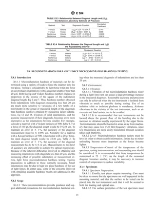
10.7.1.1 Consider introducing a 1 % error into the hardness
of the material through an error in either the applied force, the
indenter constant or the measured diagonal length. In this case,
the hardness would be HV8 = 505 or dV = 5. Using Eq 11-13,
the corresponding errors in the various parameters are as
shown in Table 1. Thus a 1 % change in P or a 2.09 % error in
a creates a 1 % error in the Vickers hardness number. How-
ever, only a 0.5 % error in the measured diagonal is needed to
create a 1 % error in Vickers hardness. Furthermore, this
analysis indicates that the calculated Vickers hardness number
is not strongly influenced by errors in the angle of the indenter.
10.7.2 Knoop—Similarly, using Eq 1, it follows that:
dK 5 S] K
]P DdP 1 S] K
] cp
Ddcp 1 S] K
] d Ddd (14)
103
cp d2 dP 1
103
P
cp
2
d2 dcp 1
–2 3 103
P
cp d3 dd (15)
6
Supporting data have been filed at ASTM Headquarters. Request RR:E-04-
1004.
7
The boldface numbers in parentheses refer to the list of references at the end of
this standard.
E 384
6](https://image.slidesharecdn.com/standardtestmethodformicroindentatio-220328144218/85/Standard_Test_Method_for_Microindentatio-pdf-6-320.jpg)
![and since the indenter has two different angles, A and B,
dcp 5 S] cp
] A DdA 1 S] cp
]B DdB (16)
S ] cp
] / AD5
–tan S/ B
2 D
4 sin2
S/A
2 D
(17)
and
S ] cp
] / BD5
cot S/ A
2 D
4 cos2
S/ B
2 D
(18)
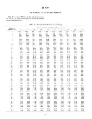
10.7.2.1 Using the differentials cited in 10.7.2, for the
Knoop test at various forces, for a 1 % error in hardness that is,
KH8 = 505 or dK = 5, the corresponding errors in the force,
diagonal measurement and indenter angle are as shown in
Table 2. From this analysis it follows that 1 % error in P creates
a 1 % error in HK, 0.5 % error in the measured diagonal creates
a 1 % error in HK, and 1 % error in c creates a 1 % error in HK.
10.7.2.2 Since the indenter constant is composed of terms
from two different angles, either a 48 39 error in /A, or a 268
209 error in /B produces a 1 % error in HK. Unlike the
Vickers indenter, the calculated Knoop hardness number is
very strongly influenced by small errors in the two angles of
the indenter. The A angle, 172° 308 009, is the most sensitive of
these parameters. The actual value of cp for each indenter can
be calculated using the certified A and B angles provided by the
indenter manufacturer. This will enhance the accuracy of the
test measurements.
10.8 An interlaboratory test program was conducted in
accordance with Practice E 691 to develop information regard-
ing the precision, repeatability, and reproducibility of the
measurement of Knoop and Vickers indentations. The test
forces were 25, 50, 100, 200, 500, and 1000 gf on three ferrous
and four nonferrous specimens (6, 7). Twelve laboratories
measured the indentations, five of each type at each force on
each sample. Additional details of this study are given in
Appendix X3.
10.8.1 Tests of the three ferrous specimens revealed that
nine laboratories produced similar measurements while two
laboratories consistently undersized the indentations and one
laboratory consistently oversized the indentations. These latter
results were most pronounced as the force decreased and
specimen hardness increased (that is, as the diagonal size
decreased) and were observed for both Vickers and Knoop
indentations. Results for the lower hardness nonferrous inden-
tations produced better agreement. However, none of the
laboratories that obtained higher or lower results on the ferrous
specimens measured the nonferrous indentations.
10.8.2 Repeatability Interval—The difference due to test
error between two test results in the same laboratory on the
same material increases with increasing specimen hardness and
with decreasing test force (see X3.4.4).
10.8.3 Reproducibility Interval—The difference in test re-
sults on the same material tested in different laboratories
increased with increasing specimen hardness and with decreas-
ing test force (see X3.4.5).
10.8.4 The within-laboratory and between-laboratory preci-
sion values improved as specimen hardness decreased and test
force increased. The repeatability interval and reproducibility
interval were generally larger than the precision estimate,
particularly at low test forces and high specimen hardnesses.
11. Conversion to Other Hardness Scales or Tensile
Strength Values
11.1 There is no generally accepted method for accurate
conversion of Knoop or Vickers hardness numbers to other
hardness scales or tensile strength values. Such conversions are
limited in scope and should be used with caution, except for
special cases where a reliable basis for the conversion has been
obtained by comparison tests. Refer to Test Method E 140 for
hardness conversion tables for metals.
12. Keywords
12.1 hardness; Knoop; microindentation; Vickers
TABLE 1 Vickers Hardness Analysis—1 % Error
1 % Error
Force, gf Diagonal, µm D P, gm D Diagonal, µm D Angle, °
10 6.090 0.100 –0.030 2.836
20 8.612 0.200 –0.043 2.836
50 13.617 0.499 –0.068 2.836
100 19.258 0.999 –0.096 2.836
200 27.235 1.998 –0.136 2.836
500 43.062 4.994 –0.215 2.836
1000 60.899 9.988 –0.304 2.836
2° 508 249
TABLE 2 Knoop Hardness Analysis—1 % Error
1 % Error
Force, gm Diagonal, µm D P gm
D diagonal,
µm
D A, ° D B, °
10 16.87 0.10 –0.08 0.075 0.439
20 23.86 0.20 –0.12 0.075 0.439
50 37.72 0.50 –0.19 0.075 0.439
100 53.35 1.00 –0.27 0.075 0.439
200 75.45 2.00 –0.38 0.075 0.439
500 119.29 5.00 –0.60 0.075 0.439
1000 168.71 10.00 –0.84 0.075 0.439
48 309 268 209
E 384
7](https://image.slidesharecdn.com/standardtestmethodformicroindentatio-220328144218/85/Standard_Test_Method_for_Microindentatio-pdf-7-320.jpg)


This document describes Standard Test Method E 384 for determining microindentation hardness of materials. The standard covers using Knoop and Vickers indenters to make indentations between 1-1000 gf force. Hardness is calculated based on indentation size and geometry. Key points: - Hardness is determined by dividing force by projected area or surface area of indentation for Knoop or Vickers respectively. - Equipment must precisely control low forces and indentation size must be measured via microscope. - Specimens must be flat and polished to accurately measure indentation diagonals and calculate hardness. - Multiple sources of error exist and can affect accuracy of results, including force variation, indenter geometry, and measurement errors. Standard aims