WWW.IMTC.MY
PRESENTATION ON PIPING
14– 16 / 01/ 2025
TOPICS COVERED
Introduction To Piping System
Piping Components
Testing Of Piping Systems
Presented by:
Zainal Mohd Salleh
MSc, Ceng, CTPEng, CWI, CSWIP, ASNT LII, Tar Insp, TTT HRDF, ToT UK, ISO Auditor
WWW.IMTC.MY
PIPING SYSTEM
• Itconvey the fluids, between the various
equipment and end users.
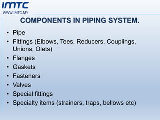
• It consists of various components such as pipes,
valves, fittings, online measuring instruments,
etc
4.
WWW.IMTC.MY
DIFFERENCE BETWEEN PIPEAND TUBE
PIPE
• It is a tubular product of circular cross section
that has specific sizes and thickness governed
by particular dimensional standards.
TUBE
• It is a hollow product having circular, elliptical or
square cross section or cross section of any
closed perimeter.
• Tubes are also used for heat transfer purpose.
5.
WWW.IMTC.MY
PIPE PRODUCTS
SEAMLESS PIPE
•A wrought tubular product made without a welded
seam by drawing or extrusion process
WELDED PIPES
• Welded pipes are manufactured by ERW ( Electric
Resistance Welded).
• Pipes in small quantities are manufactured by
EFW(electric fusion -welding) process .
• The longitudinal seam is welded by manual or
automatic electric arc process.
6.
WWW.IMTC.MY
CLASSIFICATION BASED ONEND USE
LINE PIPE
• It is mainly used for conveying fluids over long distances and
are subjected to fluid pressure It is usually not subjected to
high temperature
PRESSURE PIPE
• These are subjected to fluid pressure and /or temperature .
• Fluid pressure in generally internal pressure or may be
external pressure (e.g. jacketed piping )and are mainly used
as plant piping.
STRUCTURAL PIPE
• These are not used for conveying fluids and not subjected to
fluid pressures or temperature. They are used as structural
components (e.g handrails, columns, sleeves etc.) and are
subjected to static loads only.
7.
WWW.IMTC.MY
NOMINAL PIPE SIZE(NPS)
• Pipes are designated by nominal size, starting from
1/8” nominal size, and increasing in steps,
• For the nominal size up to including 12” there is
one unique O D (different from nominal size)and I
D would vary depending on schedule number .
• For nominal sizes 14” and above O.D is same as
nominal size.
8.
WWW.IMTC.MY
WHY PIPE SIZEIS MORE IMPORTANT
• According to American Survey 30 % of the total
cost of a chemical process plant goes for piping
elements and valves.
• Take optimum pipe size while designing the pipe
size.
9.
WWW.IMTC.MY
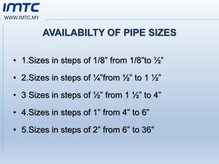
AVAILABILTY OF PIPESIZES
• 1.Sizes in steps of 1/8” from 1/8”to ½”
• 2.Sizes in steps of ¼”from ½” to 1 ½”
• 3 Sizes in steps of ½” from 1 ½” to 4”
• 4.Sizes in steps of 1” from 4” to 6”
• 5.Sizes in steps of 2” from 6” to 36”
10.
WWW.IMTC.MY
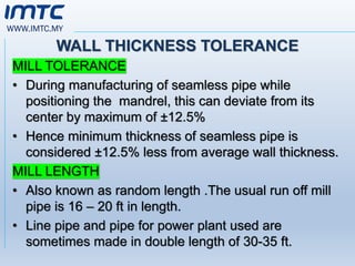
WALL THICKNESS TOLERANCE
MILLTOLERANCE
• During manufacturing of seamless pipe while
positioning the mandrel, this can deviate from its
center by maximum of ±12.5%
• Hence minimum thickness of seamless pipe is
considered ±12.5% less from average wall thickness.
MILL LENGTH
• Also known as random length .The usual run off mill
pipe is 16 – 20 ft in length.
• Line pipe and pipe for power plant used are
sometimes made in double length of 30-35 ft.
11.
WWW.IMTC.MY
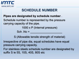
SCHEDULE NUMBER
Pipes aredesignated by schedule number .
Schedule number is represented by the pressure
carrying capacity of the pipe.
1000 x P (Internal pressure)
Sch .No = ____________________
S (Allowable tensile strength of material)
Irrespective of pipe dia, equal schedules have equal
pressure carrying capacity.
For stainless steels schedule number are designated by
suffix S ie 5S, 10S, 40S, 80S etc
WWW.IMTC.MY
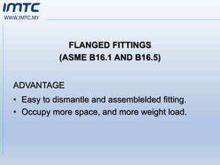
FITTINGS
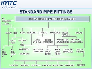
• Pipe fittingsare the components which tie together
pipelines, valves, and other parts of a piping
system.
• Fittings may come in butt Welded, Socket welded,
Screwed and flanged connections.
• They are used to change the size of the line or its
direction.
WWW.IMTC.MY
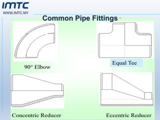
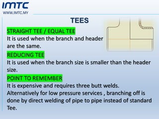
TEES
STRAIGHT TEE /EQUAL TEE
It is used when the branch and header
are the same.
REDUCING TEE
It is used when the branch size is smaller than the header
size.
POINT TO REMEMBER
It is expensive and requires three butt welds.
Alternatively for low pressure services , branching off is
done by direct welding of pipe to pipe instead of standard
Tee.
18.
WWW.IMTC.MY
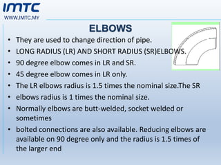
ELBOWS
• They areused to change direction of pipe.
• LONG RADIUS (LR) AND SHORT RADIUS (SR)ELBOWS.
• 90 degree elbow comes in LR and SR.
• 45 degree elbow comes in LR only.
• The LR elbows radius is 1.5 times the nominal size.The SR
• elbows radius is 1 times the nominal size.
• Normally elbows are butt-welded, socket welded or
sometimes
• bolted connections are also available. Reducing elbows are
available on 90 degree only and the radius is 1.5 times of
the larger end
19.
WWW.IMTC.MY
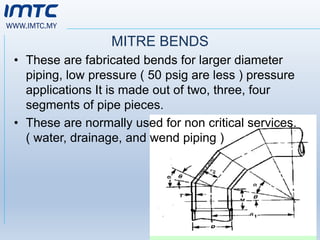
MITRE BENDS
• Theseare fabricated bends for larger diameter
piping, low pressure ( 50 psig are less ) pressure
applications It is made out of two, three, four
segments of pipe pieces.
• These are normally used for non critical services.
( water, drainage, and wend piping )
20.
WWW.IMTC.MY
COUPLINGS
• It isused to connect small bore pipes as
projection of welding inside the pipe bore reduce
the flow area
HALF COUPLING :
• It is used for branch connection
UNIONS
• It is used where dismantling of the pipe is
required more often.
• It can be with threaded end or socket weld ends.
21.
WWW.IMTC.MY
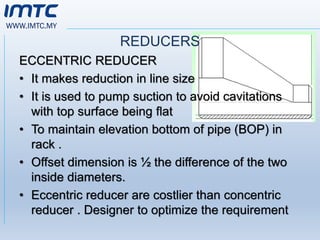
REDUCERS
ECCENTRIC REDUCER
• Itmakes reduction in line size
• It is used to pump suction to avoid cavitations
with top surface being flat
• To maintain elevation bottom of pipe (BOP) in
rack .
• Offset dimension is ½ the difference of the two
inside diameters.
• Eccentric reducer are costlier than concentric
reducer . Designer to optimize the requirement
22.
WWW.IMTC.MY
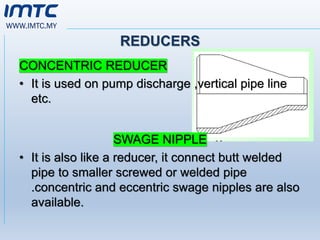
REDUCERS
CONCENTRIC REDUCER
• Itis used on pump discharge ,vertical pipe line
etc.
SWAGE NIPPLE
• It is also like a reducer, it connect butt welded
pipe to smaller screwed or welded pipe
.concentric and eccentric swage nipples are also
available.
WWW.IMTC.MY
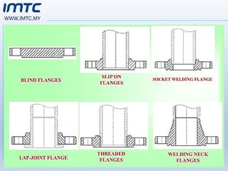
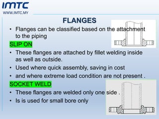
FLANGES
• Flanges canbe classified based on the attachment
to the piping
SLIP ON
• These flanges are attached by fillet welding inside
as well as outside.
• Used where quick assembly, saving in cost
• and where extreme load condition are not present .
SOCKET WELD
• These flanges are welded only one side .
• Is is used for small bore only
25.
WWW.IMTC.MY
FLANGES
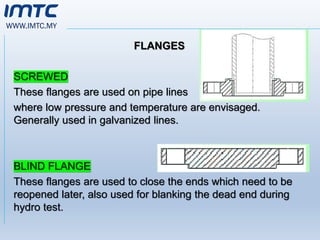
SCREWED
These flanges areused on pipe lines
where low pressure and temperature are envisaged.
Generally used in galvanized lines.
BLIND FLANGE
These flanges are used to close the ends which need to be
reopened later, also used for blanking the dead end during
hydro test.
26.
WWW.IMTC.MY
FLANGES
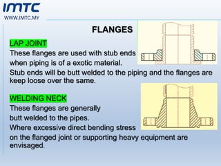
LAP JOINT
These flangesare used with stub ends
when piping is of a exotic material.
Stub ends will be butt welded to the piping and the flanges are
keep loose over the same.
WELDING NECK
These flanges are generally
butt welded to the pipes.
Where excessive direct bending stress
on the flanged joint or supporting heavy equipment are
envisaged.
27.
WWW.IMTC.MY
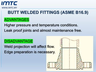
BUTT WELDED FITTINGS(ASME B16.9)
ADVANTAGES
Higher pressure and temperature conditions.
Leak proof joints and almost maintenance free.
DISADVANTAGE
Weld projection will affect flow.
Edge preparation is necessary.
28.
WWW.IMTC.MY
RATING OF FLANGE
•Flange are also classified by pressure –
temperature ratings as per ANSI B 16.5.
• It is available in seven ratings 150#, 300#, 400#,
600#, 900#, 1500# and 2500#
• These flange rating are called nominal rating.
• pressure –temperature combines determines the
flange rating.
29.
WWW.IMTC.MY
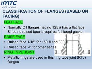
CLASSIFICATION OF FLANGES(BASED ON
FACING)
FLAT FACE
• Normally C I flanges having 125 # has a flat face.
Since no raised face it requires full faced gasket.
RAISE FACE
• Raised face 1/16” for 150 # and 300 #
• Raised face ¼” for other series
RING TYPE JOINT
• Metallic rings are used in this ring type joint (RTJ)
flanges
30.
WWW.IMTC.MY
SURFACE FINISH ONTHE FLANGE
• Normally smooth finish is recommended for
metallic gaskets.
• Serrated finish are used when non metallic
gaskets are used.
31.
WWW.IMTC.MY
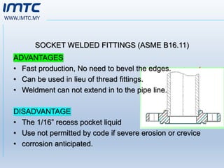
SOCKET WELDED FITTINGS(ASME B16.11)
ADVANTAGES
• Fast production, No need to bevel the edges.
• Can be used in lieu of thread fittings.
• Weldment can not extend in to the pipe line.
DISADVANTAGE
• The 1/16” recess pocket liquid
• Use not permitted by code if severe erosion or crevice
• corrosion anticipated.
WWW.IMTC.MY
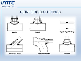
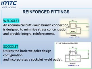
REINFORCED FITTINGS
WELDOLET
An economicalbutt -weld branch connection,
is designed to minimize stress concentration
and provide integral reinforcement.
SOCKOLET
Utilizes the basic weldolet design
configuration
and incorporates a sockolet -weld outlet.
35.
WWW.IMTC.MY
REINFORCED FITTINGS
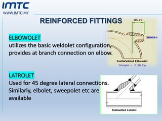
ELBOWOLET
utilizes thebasic weldolet configuration,
provides at branch connection on elbow.
LATROLET
Used for 45 degree lateral connections.
Similarly, elbolet, sweepolet etc are
available
36.
WWW.IMTC.MY
THERMAL EXPANSION OFPIPE
• Each material has its own coefficient of thermal
expansion.
• If the pipe is of carbon steel or low alloy steel, it will
expand at the rate of 6 to 7 mm every meter length
as the temperature raises to 500o C.
• To accommodate the thermal expansion, these
joints are provided.
37.
WWW.IMTC.MY
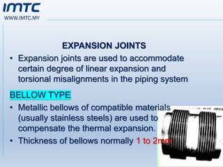
EXPANSION JOINTS
• Expansionjoints are used to accommodate
certain degree of linear expansion and
torsional misalignments in the piping system
BELLOW TYPE
• Metallic bellows of compatible materials
(usually stainless steels) are used to
compensate the thermal expansion.
• Thickness of bellows normally 1 to 2mm
38.
WWW.IMTC.MY
EXPANSION LOOPS
• Expansionloops are widely used for high
temperatures & high pressures applications.
Ideally suitable for longitudinal movements and
certain degree of torsional movement.
TELESCOPIC TYPE
• These joints ideally suitable for low temperature
& low pressure application. Suitable only for
axial expansion
39.
WWW.IMTC.MY
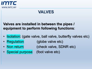
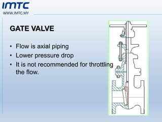
VALVES
Valves are installedin between the pipes /
equipment to perform following functions:
• Isolation: (gate valve, ball valve, butterfly valves etc)
• Regulation (globe valve etc)
• Non return (check valve, SDNR etc)
• Special purpose (foot valve etc)
40.
WWW.IMTC.MY
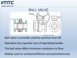
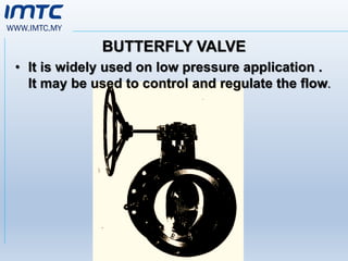
BALL VALVE
Ball valveis normally used for positive shut off.
Operation by a quarter turn of operating handle.
The ball valve offers minimum resistance to flow.
Widely used on onshore/offshore and petrochemicals
41.
WWW.IMTC.MY
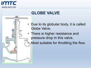
GLOBE VALVE
• Dueto its globular body, it is called
Globe Valve.
• There is higher resistance and
pressure drop in this valve.
• Most suitable for throttling the flow.
WWW.IMTC.MY
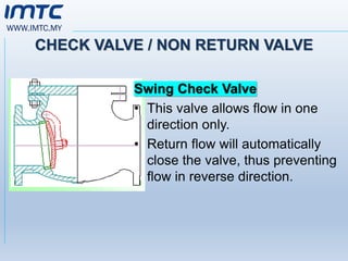
CHECK VALVE /NON RETURN VALVE
Swing Check Valve
• This valve allows flow in one
direction only.
• Return flow will automatically
close the valve, thus preventing
flow in reverse direction.
45.
WWW.IMTC.MY
TESTING OF PIPINGSYSTEM
(AS PER ANSI B 31.3)
Piping system can be tested for leak tightness and
pressure integrity by hydro test / pneumatic test
methods
46.
WWW.IMTC.MY
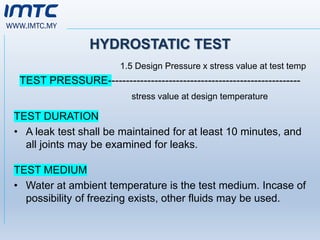
HYDROSTATIC TEST
1.5 DesignPressure x stress value at test temp
TEST PRESSURE------------------------------------------------------
stress value at design temperature
TEST DURATION
• A leak test shall be maintained for at least 10 minutes, and
all joints may be examined for leaks.
TEST MEDIUM
• Water at ambient temperature is the test medium. Incase of
possibility of freezing exists, other fluids may be used.
47.
WWW.IMTC.MY
PNEUMATIC TEST
TEST PRESSURE
•(1.1 x Design Pressure x stress value at test
Temperature) / stress value at design temperature
TEST DURATION
• A leak test shall be maintained for at least 10
minutes, and all joints may be examined for leaks.
TEST MEDIUM
• Air at ambient temperature is the test medium
48.
WWW.IMTC.MY
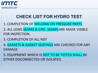
CHECK LIST FORHYDRO TEST
1. COMPLETION OF WELDING ON PRESSURE PARTS
2. ALL LONG SEAMS & CIRC. SEAMS ARE MADE VISIBLE
FOR INSPECTION.
3. COMPLETION OF ALL NDT
4. GASKETS & GASKET SEATINGS ARE CHECKED FOR ANY
DAMAGE
5. EQUIPMENT WHICH IS NOT TO BE TESTED SHALL BE
EITHER DISCONNECTED OR ISOLATED.
49.
WWW.IMTC.MY
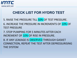
CHECK LIST FORHYDRO TEST
5. RAISE THE PRESSURE TILL 50% OF TEST PRESSURE.
6. INCREASE THE PRESSURE IN INCREMENTS OF 10% OF
TEST PRESSURE
7. STOP PUMPING FOR 5 MINUTES AFTER EACH
INCREMENT OF 10% OF RISE IN PRESSURE.
8. IF ANY LEAKAGE IS OBSERVED THROUGH GASKET
CONNECTION, REPEAT THE TEST AFTER DEPRESSURISING
THE SYSTEM
WWW.IMTC.MY
IMPORTANT SAFETY POINTS
DRAINTHE PIPE ONLY WHEN TOP OUT LET IS KEPT OPEN
• USE MINIMUM 2 GAUGES FOR ANY HYDROTEST
• NEVER USE HIGH DISCHARGE PUMPS FOR TESTING LOW
VOLUME PIPE. ( VOLUM LESS THAN 10 M3).
• NEVER PRESSURISE ANY VESSEL ABOVE TEST PRESSURE
52.
WWW.IMTC.MY
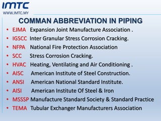
COMMAN ABBREVIATION INPIPING
• EJMA Expansion Joint Manufacture Association .
• IGSCC Inter Granular Stress Corrosion Cracking.
• NFPA National Fire Protection Association
• SCC Stress Corrosion Cracking.
• HVAC Heating, Ventilating and Air Conditioning .
• AISC American Institute of Steel Construction.
• ANSI American National Standard Institute.
• AISI American Institute Of Steel & Iron
• MSSSP Manufacture Standard Society & Standard Practice
• TEMA Tubular Exchanger Manufacturers Association
53.
WWW.IMTC.MY
REASON FOR CHECKING1.5 TIMES OF
DESIGN PRESSURE
Normally 66% of yield strength (ie 2/3 yield strength) or
1/3
of the tensile strength which ever is less is taken as a basic
Allowable stress for metals considered for design
calculation
when you test the materials for 1.5 times of the design
pressure it is not exceeding 100% of yield strength of the
material.
Hence all pipelines are tested for 1.5 times of the design
pressure .
2/3 of yield strength is 66 %
1.5 times of 66 % is 99 %
WWW.IMTC.MY
REASON FOR 22%ELONGATION
ON STEEL
.
• Normally 12 % of the ductility required in final
product.during manufacturing. 6 to 8 % ductility
lost in manufacturing and 2 % is considered for
non -homogenous material.
• Hence material selected should have minimum
22 % elongation.
57.
WWW.IMTC.MY
PIPING FABRICATION
- cutting
-bending
- forming
- welding
Cutting and beveling of the edges by Mechanical
Methods (lathes, grinding Wheels / Thermal methods
(oxy – fuel gas cutting, Arc cutting.)
58.
WWW.IMTC.MY
PIPING
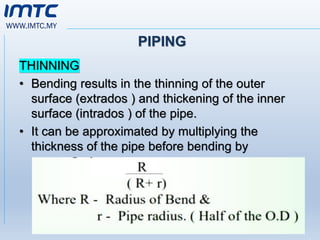
THINNING
• Bending resultsin the thinning of the outer
surface (extrados ) and thickening of the inner
surface (intrados ) of the pipe.
• It can be approximated by multiplying the
thickness of the pipe before bending by
59.
WWW.IMTC.MY
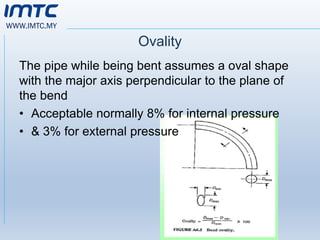
Ovality
The pipe whilebeing bent assumes a oval shape
with the major axis perpendicular to the plane of
the bend
• Acceptable normally 8% for internal pressure
• & 3% for external pressure
60.
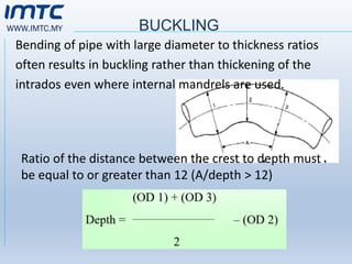
WWW.IMTC.MY BUCKLING
Bending ofpipe with large diameter to thickness ratios
often results in buckling rather than thickening of the
intrados even where internal mandrels are used.
Ratio of the distance between the crest to depth must
be equal to or greater than 12 (A/depth > 12)
61.
WWW.IMTC.MY
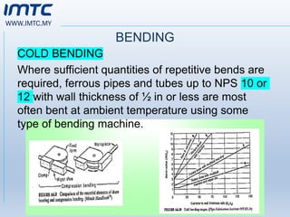
BENDING
COLD BENDING
Where sufficientquantities of repetitive bends are
required, ferrous pipes and tubes up to NPS 10 or
12 with wall thickness of ½ in or less are most
often bent at ambient temperature using some
type of bending machine.
62.
WWW.IMTC.MY
HOT BENDING
• ]Carriedout in the temperature range of 1036*c to
1121*c by
• induction bending. Where suitable cold bending
equipment is unavailable
• Pipes of size NPS 3 ½ to NPS 64, radius of 8 to
400 inch and wall thickness 4” can be bend by
Induction Bender .
63.
WWW.IMTC.MY
THANK YOU
For YourKindness
Presented by:
Zainal Mohd Salleh
MSc, Ceng, CTPEng, CWI, CSWIP, ASNT LII, Tar Insp, TTT HRDF, ToT UK, ISO Auditor


![WWW.IMTC.MY
HOT BENDING
• ]Carried out in the temperature range of 1036*c to
1121*c by
• induction bending. Where suitable cold bending
equipment is unavailable
• Pipes of size NPS 3 ½ to NPS 64, radius of 8 to
400 inch and wall thickness 4” can be bend by
Induction Bender .](https://image.slidesharecdn.com/2-250420045227-ccbfe334/85/2-Piping-System-2-pdf-62-320.jpg)