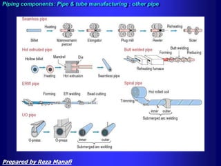
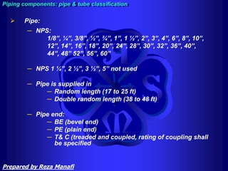
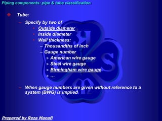
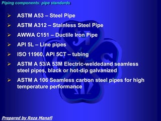
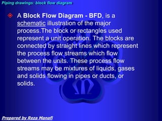
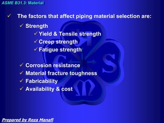
The document provides an overview of process plant piping systems and their components. It defines piping as assemblies used for fluid flows that can include pipes, fittings, valves, and supports. Key piping components are then described, including various types of pipes and tubes based on material and manufacturing method. Common fitting types are also outlined for butt-weld, socket-weld, and threaded joints, such as elbows, tees, reducers, and caps. Standards for different pipe and fitting materials are also briefly mentioned.

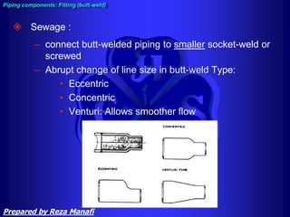
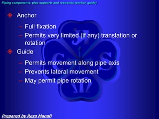
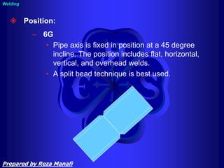
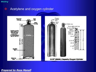
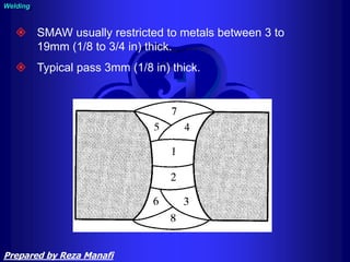
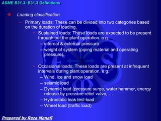
![ piping:
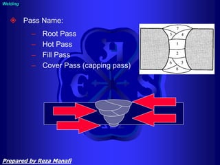
assemblies of piping components
used…[for] fluid flows. Piping also
includes pipe supporting elements, but
does not include support structures…or
equipment…
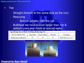
piping system:
interconnected piping subject to the
same design conditions
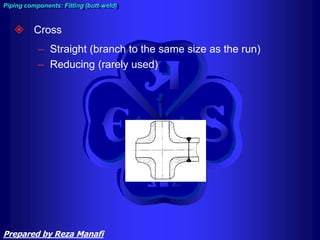
Definition:
Prepared by Reza Manafi](https://image.slidesharecdn.com/piping-training-course-240227183626-923f9f60/85/Piping-Training-Coursebplant-system1-ppt-4-320.jpg)


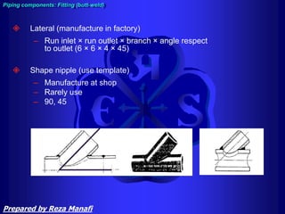


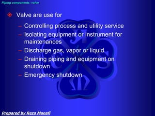


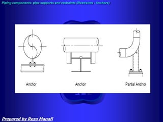


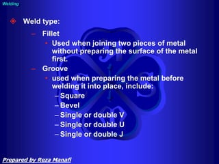


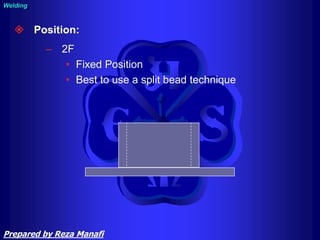

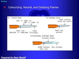


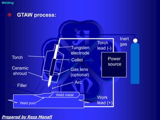


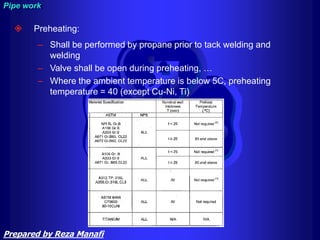


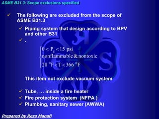


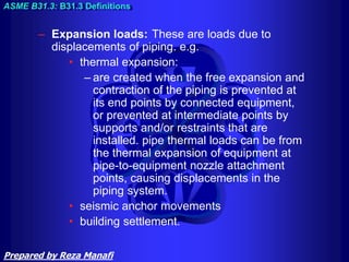
![ High Pressure:
– A service for which the owner
specifies the use of Chapter IX [of
B31.3] for piping design and
construction… considered to be in
excess of Class 2500 (PN 420).
Characterized as “high pressure”
Normal: Everything else.
– Often characterized as “process”
ASME B31.3: B31.3 Fluid Service Definitions
Prepared by Reza Manafi](https://image.slidesharecdn.com/piping-training-course-240227183626-923f9f60/85/Piping-Training-Coursebplant-system1-ppt-427-320.jpg)
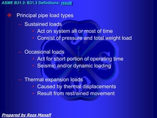

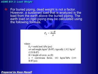
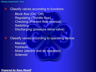
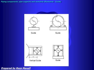
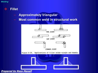
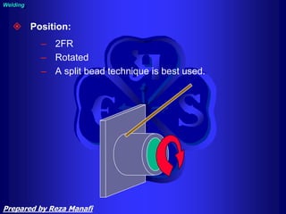
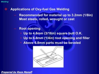
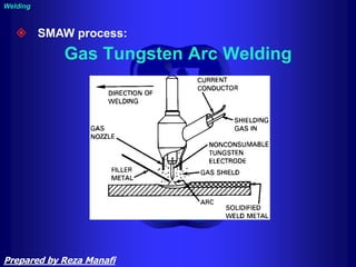
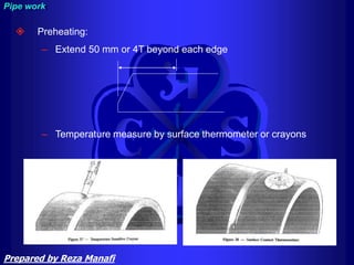
![ The design pressure of a piping system is the pressure at the
most severe condition of coincident internal or external pressure
and temperature expected during service. unless all of the
following criteria are met.
– The piping system have no pressure containing components
of cast iron or other non ductile metal.
– Nominal pressure stresses shall not exceed the yield
strength, Sy data in [ASME] BPV Code, Section II, Part D,
Table Y-1).
– The total number of pressure-temperature variations shall not
exceed 1000 during the life of the piping system.
– Increased pressure shall not exceed the test pressure
ASME B31.3: Design pressure
Prepared by Reza Manafi](https://image.slidesharecdn.com/piping-training-course-240227183626-923f9f60/85/Piping-Training-Coursebplant-system1-ppt-439-320.jpg)

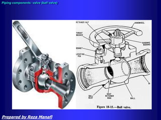
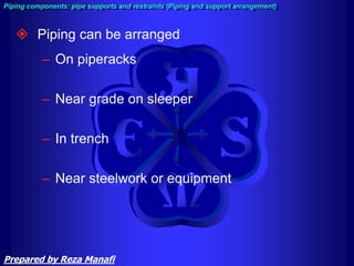
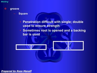
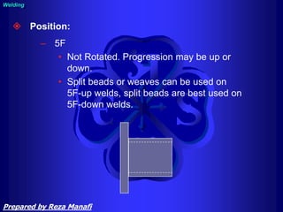
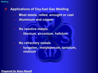
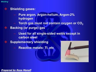
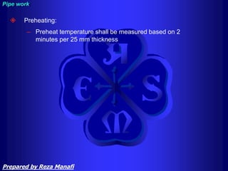
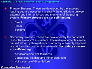
![– The combined effects of the sustained and cyclic
variations shall have been evaluated.
– Temperature variations below the minimum
temperature shown in Appendix A [of ASME B31.3]
are not permitted.
– The application of pressures exceeding pressure-
temperature ratings of valves may cause loss of
seat tightness or difficulty of operation. The
differential pressure on the valve closure element
should not exceed the maximum differential
pressure rating established by the valve
manufacturer.
ASME B31.3: Design pressure
Prepared by Reza Manafi](https://image.slidesharecdn.com/piping-training-course-240227183626-923f9f60/85/Piping-Training-Coursebplant-system1-ppt-441-320.jpg)