

Recommended
More Related Content
What's hot
What's hot (20)
Similar to Speed control of dc motors
Similar to Speed control of dc motors (20)
More from Dr.Raja Masood Larik
More from Dr.Raja Masood Larik (20)
Recently uploaded
Recently uploaded (20)
Speed control of dc motors
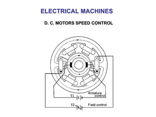
- 1. ELECTRICAL MACHINES D. C. MOTORS SPEED CONTROL
- 2. 2 INTRODUCTION • The principal advantage of a d.c. motor is that its speed can be changed over a wide range by simple methods • Such a fine speed control is generally not possible with a.c. motors. In a.c motor speed control is very difficult compare to d.c machines. • Fine speed control is one of the reasons for the strong competitive position of d.c. motors in the modern industrial applications. Specially in Textile and Rolling mills. Lecture Notes by Dr.R.M.Larik
- 3. 3 SPEED CONTROL OF D.C. MOTOR Speed of a d.c. motor is given by: N Eb Φ or N = K V− Ia R Φ rpm (as Eb = V − IaRa) where R = Ra for shunt motor R = Ra + Rse for series motor From above, it is clear that there are three main methods of controlling the speed of a d.c. motor, namely: i) By varying the flux per pole (ϕ), known as flux control method ii) By varying the resistance in the armature circuit, known as armature control method. iii) By varying the applied voltage V, known as voltage control method Lecture Notes by Dr.R.M.Larik
- 4. 4 SPEED CONTROL OF D.C. SHUNT MOTORS ➢ Flux control method • Based on the fact that by varying the flux Φ, the motor speed (N 1 Φ ) can be changed and hence the name flux control method • In this method, a variable resistance is placed in series with shunt field winding • We can only raise the speed of the motor above the normal speed • Generally, this method permits to increase the speed in the ratio 3:1. Lecture Notes by Dr.R.M.Larik
- 5. 5 SPEED CONTROL OF D.C. SHUNT MOTORS (Contd.) i) This is an easy and convenient method. ii) It is an inexpensive method since very little power is wasted in the shunt field rheostat due to small value of Ish. iii) The speed control exercised by this method is independent of load on the machine. ➢Advantages ➢Disadvantages i) Only speeds higher than the normal speed can be obtained since the total field circuit resistance cannot be reduced below Rsh (the shunt field winding resistance) ii) There is a limit to the maximum speed obtainable by this method because if the flux is too much weakened, commutation becomes poorer. Lecture Notes by Dr.R.M.Larik
- 6. 6 SPEED CONTROL OF D.C. SHUNT MOTORS (Contd.) • Based on the fact that by varying the voltage available across the armature, the back e.m.f and hence the speed of the motor can be changed. • Done by inserting a variable resistance RC (known as controller resistance) in series with the armature N V − Ia (Ra + RC) where RC = controller resistance ➢Armature Control Method Lecture Notes by Dr.R.M.Larik
- 7. 7 SPEED CONTROL OF D.C. SHUNT MOTORS (Contd.) • Due to voltage drop in the RC, the back e.m.f. (Eb) is decreased • The speed of the motor is reduced as N Eb • The highest (normal) speed obtainable is that corresponding to Rc = 0 • This method can only provide speeds below the normal speed ➢Armature Control Method (Contd.) Disadvantages • Power loss in the Rc is high since it carries full armature current • The speed varies with load as the speed depends upon Ia Rc • The efficiency of the motor are reduced. • This method results in poor speed regulation. Due to above disadvantages, this method is seldom used to control the speed of shunt motors. Lecture Notes by Dr.R.M.Larik
- 8. 8 SPEED CONTROL OF D.C. SHUNT MOTORS (Contd.) o In this method, the field current is supplied from a separate source. o This method avoids the disadvantages of poor speed regulation and low efficiency as in armature control method ➢Voltage Control Method ✓ Multiple Voltage Control • In this method, the shunt field of the motor is connected permanently across a-fixed voltage source. • The armature can be connected across several different voltages through a suitable switchgear so that voltage applied to the armature can be changed Lecture Notes by Dr.R.M.Larik
- 9. 9 SPEED CONTROL OF D.C. SHUNT MOTORS (Contd.) ➢Voltage Control Method (Contd.) ✓ Ward-Leonard System The Ward Leonard system is very important and useful method of controlling the speed of a d.c motor. The adjustable voltage for the armature is obtained from an adjustable- voltage generator while the field circuit is supplied from a separate source. G: Generator; E: Exciter FC: Field ControllerLecture Notes by Dr.R.M.Larik
- 10. 10 SPEED CONTROL OF D.C. SHUNT MOTORS (Contd.) ✓ Ward-Leonard System (Contd.) Advantages a) Motor speed can be adjusted through a wide range without resistance loss b) The motor can be brought to a standstill quickly, simply by rapidly reducing the generator voltage resulting in reduction of the back e.m.f. of the motor, and establishing dynamic braking. c) This method is used for the speed control of large motors when a d.c. supply is not available. The disadvantage of the method is that a special motor-generator set is required for each motor and the losses in this set are high if the motor is operating under light loads for long periods. Lecture Notes by Dr.R.M.Larik
- 11. 11 NUMERICAL PROBLEMS (Contd.) Problem 4(a) A 220 V, 15 kW, 850 r.p.m. shunt motor draws 72.2 A when operating at rated condition. The resistances of the armature and shunt field are 0.25 and 100 respectively. Determine the percentage reduction in field flux in order to obtain a speed of 1650 r.p.m. when armature current drawn is 40 A. Solution: Voltage supply = 220 V DC, Motor rating = 15 kW, N1 = 850 rpm, IL = 72.2 A, Ra = 0.25 , Rsh = 100 , N2 = 1650 rpm, Ia2 = 40 A % reduction in field flux ? (at 1650 rpm) N2 N1 = Eb2 Eb1 x Φ1 Φ2 Ish = V Rsh = 220 100 = 2.2 A Ia1 = IL – Ish = 72.2 – 2.2 = 70 A Lecture Notes by Dr.R.M.Larik
- 12. 12 NUMERICAL PROBLEMS (Contd.) Problem 6(a) A 240 V d.c. shunt motor has an armature-resistance of 0.25 ohm, and runs at 1000 r.p.m., taking an armature current 40 A. It is desired to reduce the speed to 800 r.p.m. (i) If the armature current remains the same, find the additional resistance to be connected in series with the armature-circuit. (ii) If, with the above additional resistance in the circuit, armature current decreases to 20 A, find the speed of the motor. Lecture Notes by Dr.R.M.Larik
- 13. 13 NUMERICAL PROBLEMS (Contd.) Problem 6(a) Solution: Supply = 240 V DC, Ra = 0.25 , N1 = 1000 rpm, Ia1= 40 A, N2 = 800 rpm, Ia3 = 20 A Additional resistance ? (for Ia1 = Ia2), Additional resistance ? (for Ia3 = 20 A) Back e.m.f. Eb1 = V – Ia1 Ra = 240 – 40 x 0.25 = 230 V Eb1 1000 r.p.m., Eb2 800 r.p.m. Eb2 Eb1 = 800 1000 Eb2 230 = 800 1000 Eb2 = 184 V Lecture Notes by Dr.R.M.Larik
- 14. 14 NUMERICAL PROBLEMS (Contd.) Problem 6(a) Solution (Contd.): Also Back e.m.f. Eb2 = V – Ia2 (R + Ra) 184 = 240 – 40 x (R + 0.25) R = 1.15 Back e.m.f. Eb3 = V – Ia3 (R + Ra) = 240 – 20(1.15 + 0.25) = 212 V Eb3 Eb1 = N3 N1 212 230 = N3 1000 , and N3 = 922 r.p.m. Problem 6(b): A 250 V shunt motor has an armature current of 20 A when running at 1000 r.p.m. against full-load torque. The armature resistance is 0.5 . What resistance must be inserted in series with the armature to reduce the speed to 500 r.p.m. at the same torque? What will be the speed if load torque is halved with this resistance in the circuit? Assume the flux to remain constant throughout and neglect brush contact drop.Lecture Notes by Dr.R.M.Larik
- 15. 15 SPEED CONTROL OF SERIES MOTORS ➢Flux Control Method In this method, the flux produced by the series motor is varied and hence the speed. ✓Field diverters • A variable resistance (field diverter) is connected in parallel with series field winding • Some portion of the line current is shunted from the series field winding, thus weakening the field and increasing the speed Lecture Notes by Dr.R.M.Larik
- 16. 16 SPEED CONTROL OF SERIES MOTORS (Contd.) ➢Flux Control Method (Contd.) ✓ Armature Diverter • To obtain speeds below the normal speed, a variable resistance (armature diverter) is connected in parallel with the armature • The diverter shunts some of the line current, thus reducing the armature current. • For a given load, if Ia is decreased, the flux Φ must increase (T ϕ Ia). and the motor speed is decreased (as N Τ1 ϕ). • By using the armature diverter, any speed lower than the normal speed can be obtained. Lecture Notes by Dr.R.M.Larik
- 17. 17 SPEED CONTROL OF SERIES MOTORS (Contd.) ➢Flux Control Method (Contd.) ✓ Tapped Field Control • The flux is reduced by decreasing the number of turns of the series field winding, hence, speed is increased. • The switch S can short circuit any part of the field winding, thus decreasing the flux and raising the speed. • With full turns of the field winding, the motor runs at normal speed and as the field turns are cut out, speeds higher than normal speed are achieved. Lecture Notes by Dr.R.M.Larik
- 18. 18 SPEED CONTROL OF SERIES MOTORS (Contd.) ➢Flux Control Method (Contd.) ✓ Paralleling Field Coils • This method is usually employed in the case of fan motors. • By regrouping the field coils several fixed speeds can be obtained. Lecture Notes by Dr.R.M.Larik
- 19. 19 SPEED CONTROL OF SERIES MOTORS (Contd.) ✓Armature-resistance Control • A variable resistance is directly connected in series with the supply to the complete motor to reduce the the armature voltage and hence the speed falls. • By changing the value of variable resistance, any speed below the normal speed can be obtained. • This is the most common method employed to control the speed of d.c. series motors. • Although this method has poor speed regulation, this has no significance for series motors because they are used in varying speed applications. Lecture Notes by Dr.R.M.Larik
- 20. 20 NUMERICAL PROBLEMS (Contd.) Problem 8 A d.c. series motor runs at 1000 r.p.m. when taking 20 A at 200 V. Armature resistance is 0.5 . Series field resistance is 0.2 . Find the speed for a total current of 20 A when a diverter of 0.2 resistance is used across the series field. Flux for a field current of 10 A is 70 per cent of that for 20 A. Solution: Supply = 200 V DC, N1 = 1000 rpm, Ia = 20 A, Ra = 0.5 Ω , Rse = 0.2 Ω, Φ2 = 0.7 Φ1 N2 ? (at total current of 20 A with diverter of 0.2 Ω) N2 N1 = Eb2 Eb1 x Φ1 Φ2 Back e.m.f. without diverter resistance Eb1 = V – Ia (Ra + Rse) = 200 – 20 (0.5 + 0.2) = 186 V Lecture Notes by Dr.R.M.Larik
- 21. 21 NUMERICAL PROBLEMS (Contd.) Problem 8 Solution (Contd.): Diverter resistance = Series field resistance As the motor current 20 A is divided between the two resistances 10 A flows through series field and produces 70% flux as compared to 20 A. Combined resistance = 0.2 2 = 0.1 Ω Motor resistance = 0.5 + 0.1 = 0.6 Ω Back e.m.f. Eb2 = V – Ia2 (Ra + Rse/div) = 200 – 20 x (0.5 + 0.1) = 188 V N2 1000 = 188 186 x 1 0.7 N2 = 1444 r.p.m. Lecture Notes by Dr.R.M.Larik
- 22. 22 SERIES - PARALLEL CONTROL • In the system, used in traction, two (or more) similar d.c. series motors are mechanically coupled to the same load. • When connected in series, each motor armature will receive one-half the normal voltage, hence, the speed will be low. • When connected in parallel, each motor armature receives the normal voltage and the speed is high Lecture Notes by Dr.R.M.Larik
- 23. 23 SERIES-PARALLEL CONTROL (Contd.) ➢Series-Parallel and Resistance Control • At standstill, the motors are connected in series via a starting rheostat. • The motors are started up in series and starting resistance is cut out step by step to increase the speed. Lecture Notes by Dr.R.M.Larik
- 24. 24 SERIES-PARALLEL CONTROL (Contd.) ➢Series-parallel and resistance control (Contd.) • To increase the speed further, the two motors are connected in parallel and at the same time the starting resistance is connected in series. • The starting resistance is again cut out step by step until full speed is attained. • Then field control is introduced.Lecture Notes by Dr.R.M.Larik
- 25. 25 SPEED CONTROL OF COMPOUND MOTORS • Speed control of compound motors may be obtained by any one of the methods described for shunt motors. • Speed control cannot be obtained through adjustment of the series field since such adjustment would radically change the performance characteristics of the motor. Lecture Notes by Dr.R.M.Larik