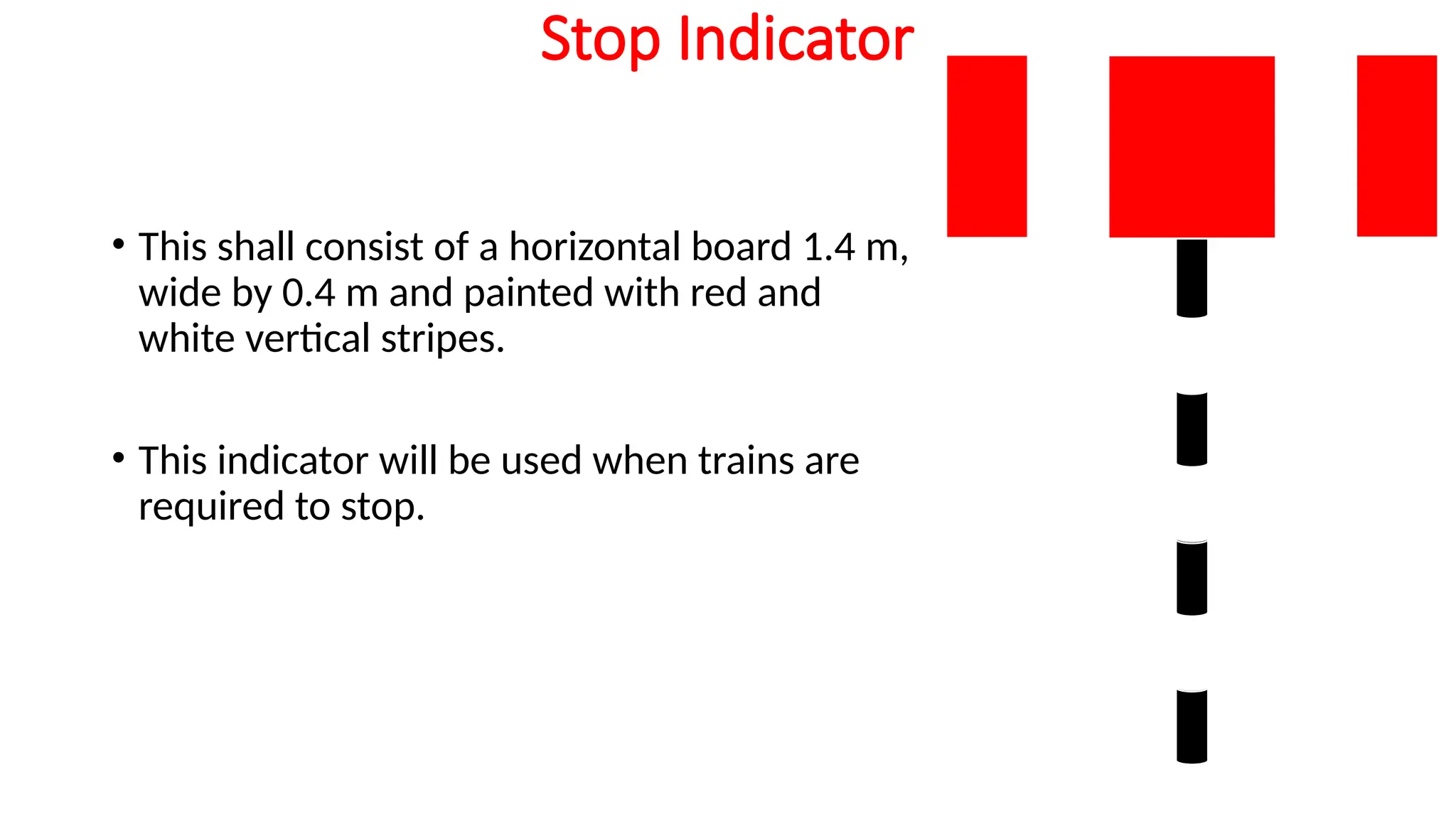
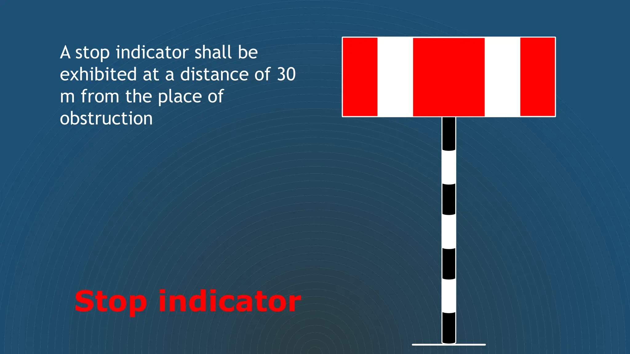
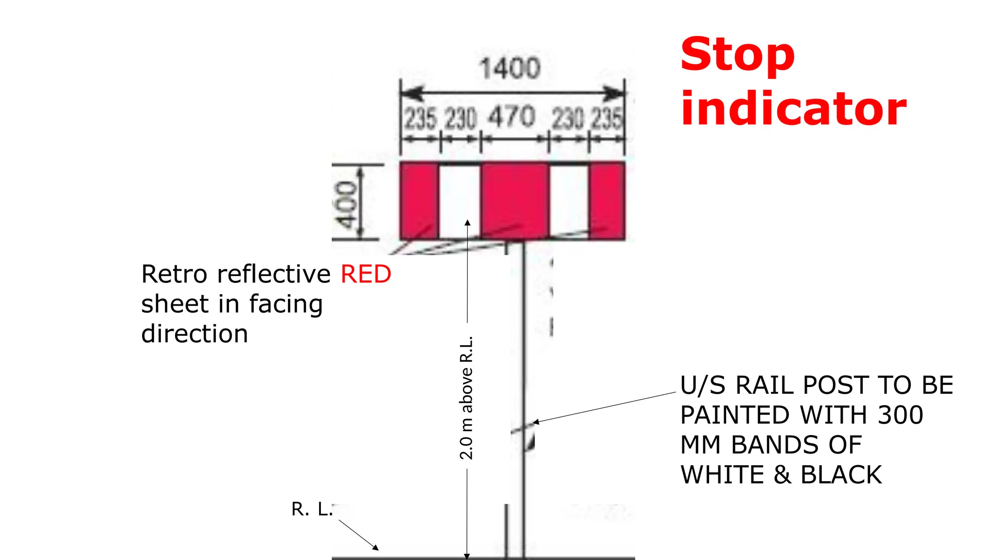
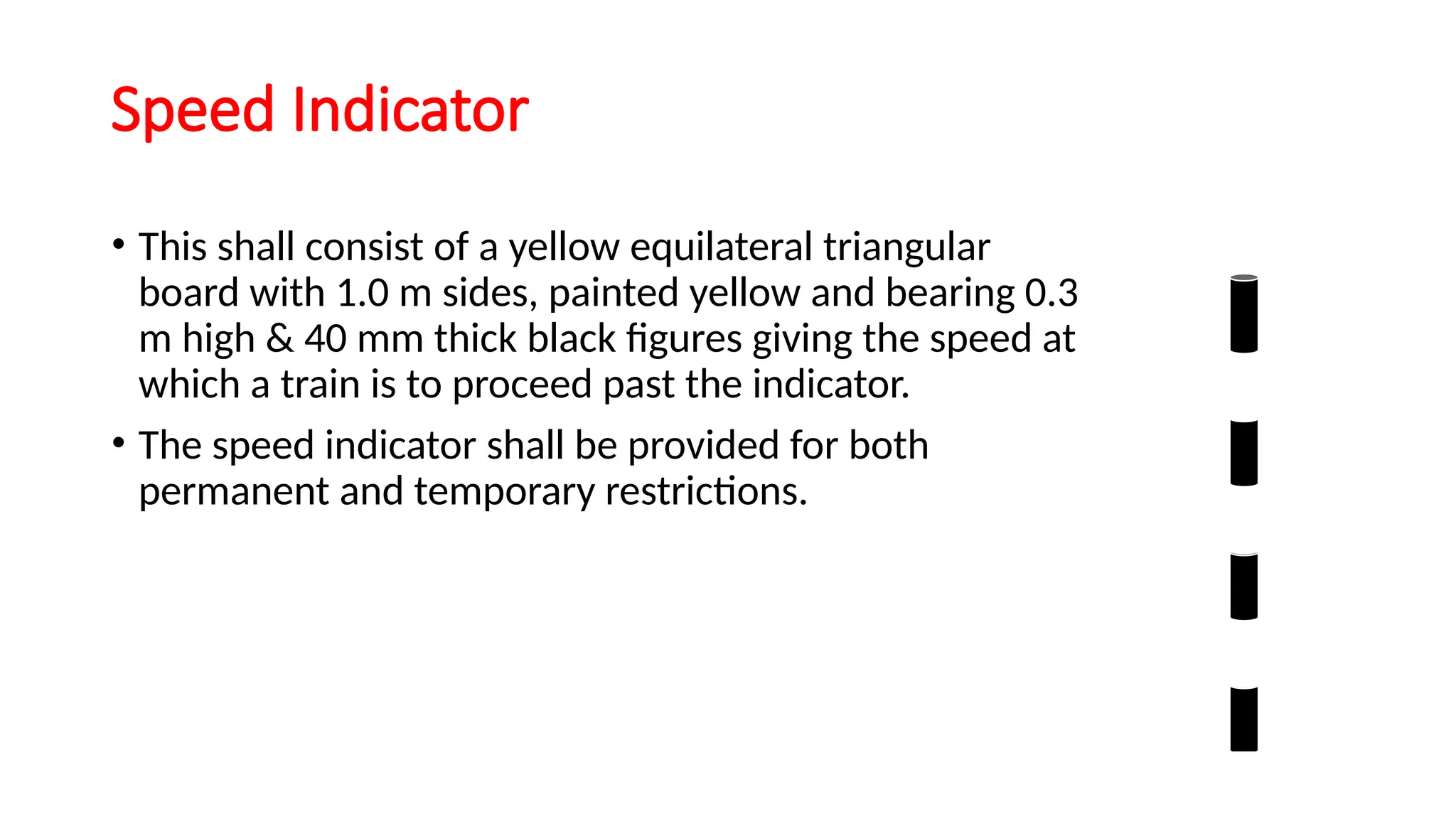
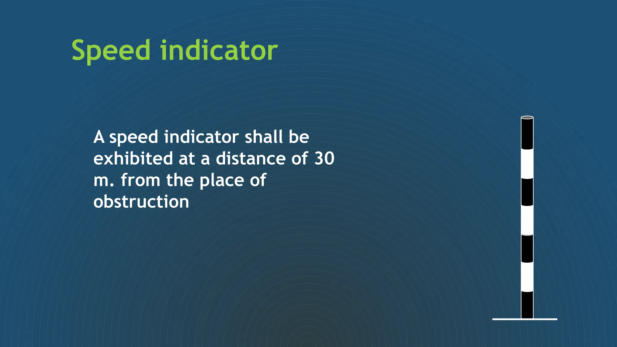
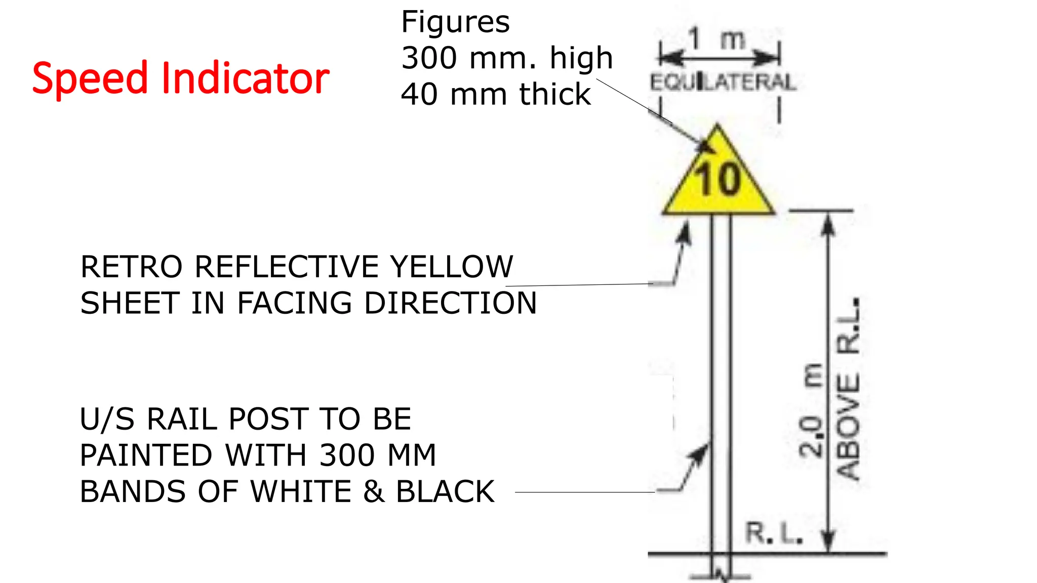
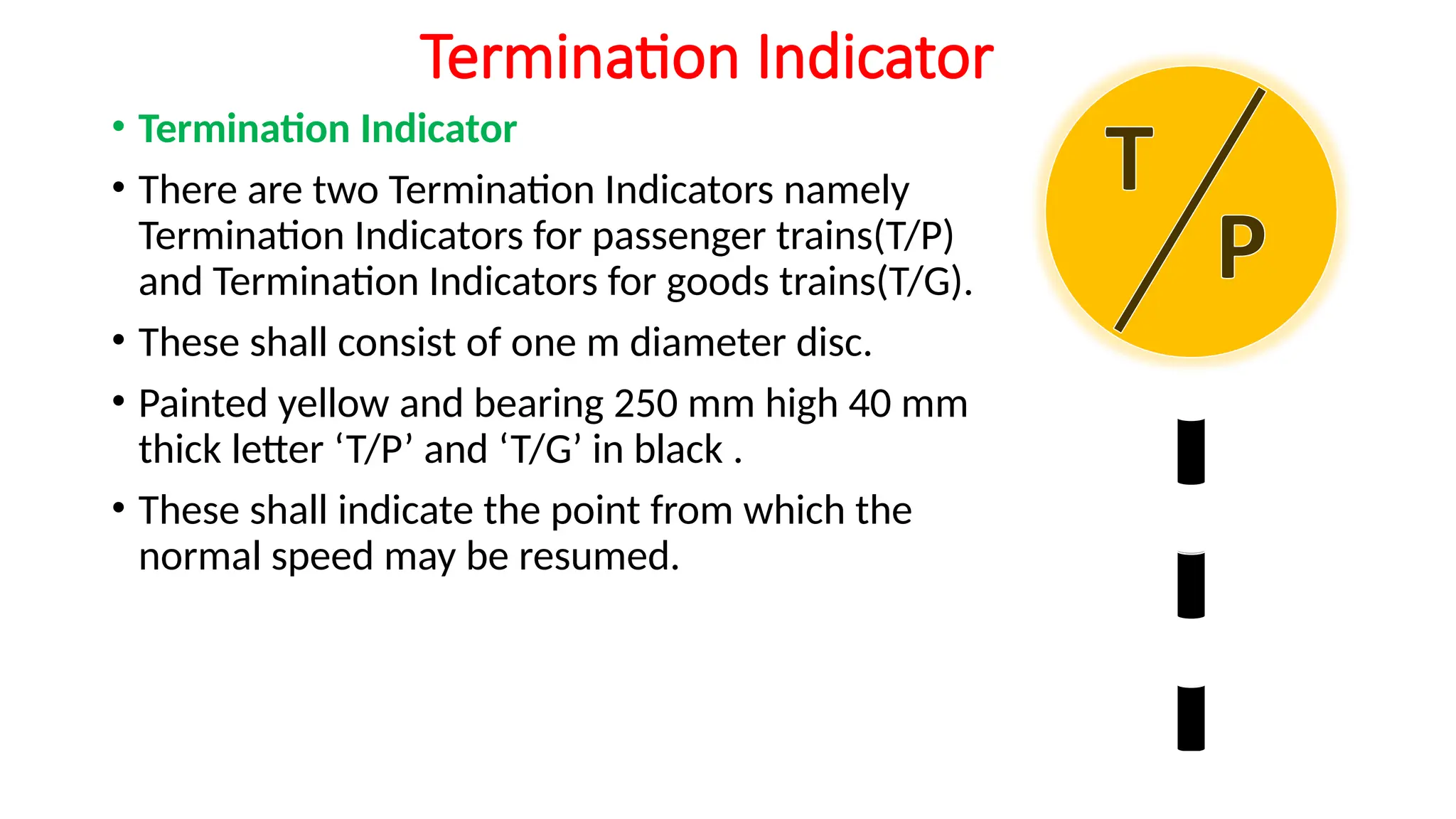
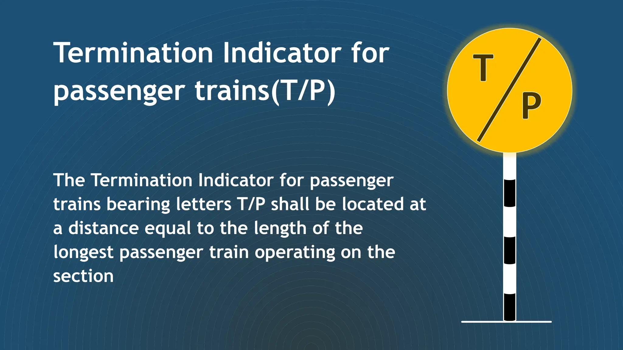
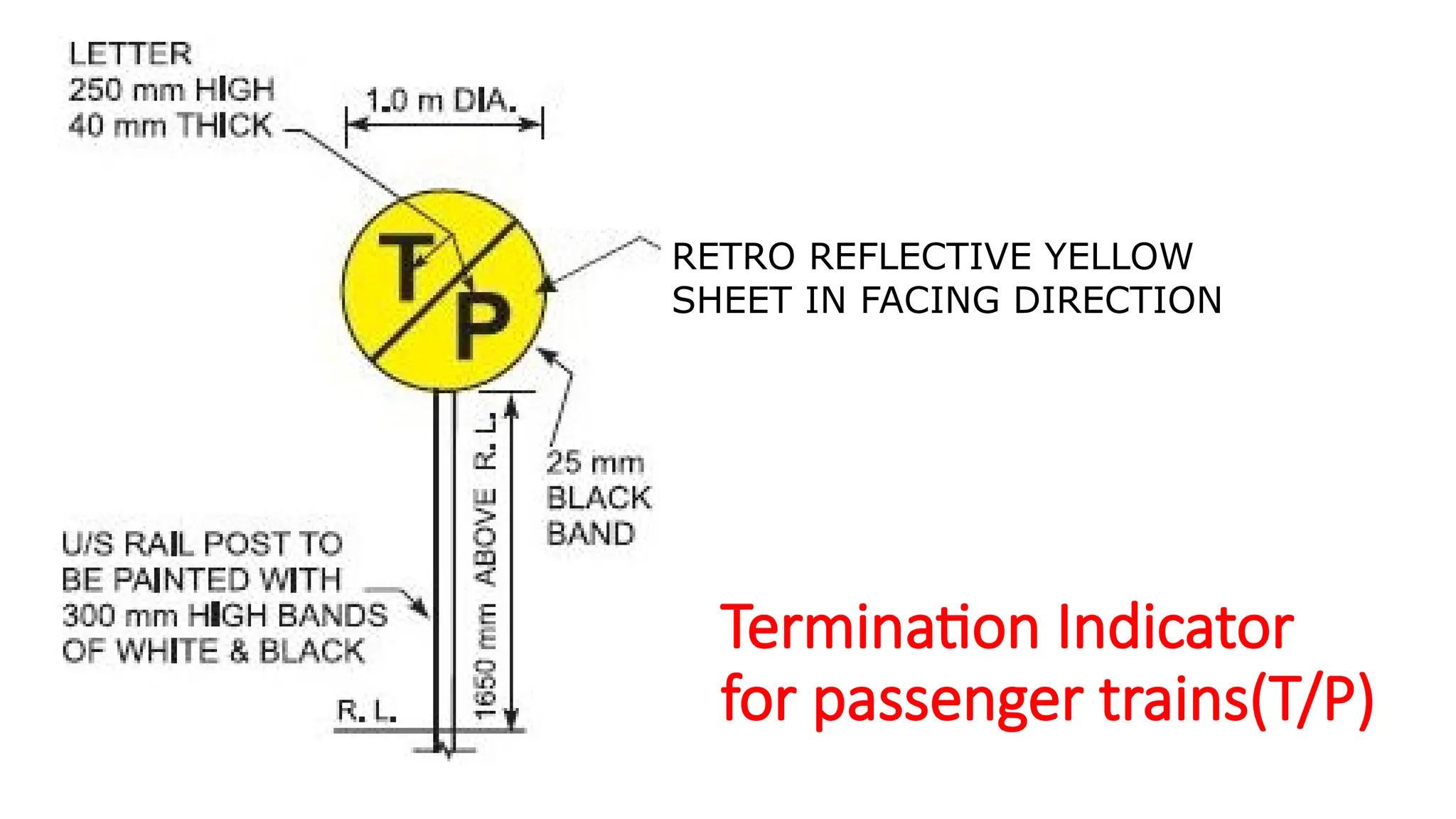
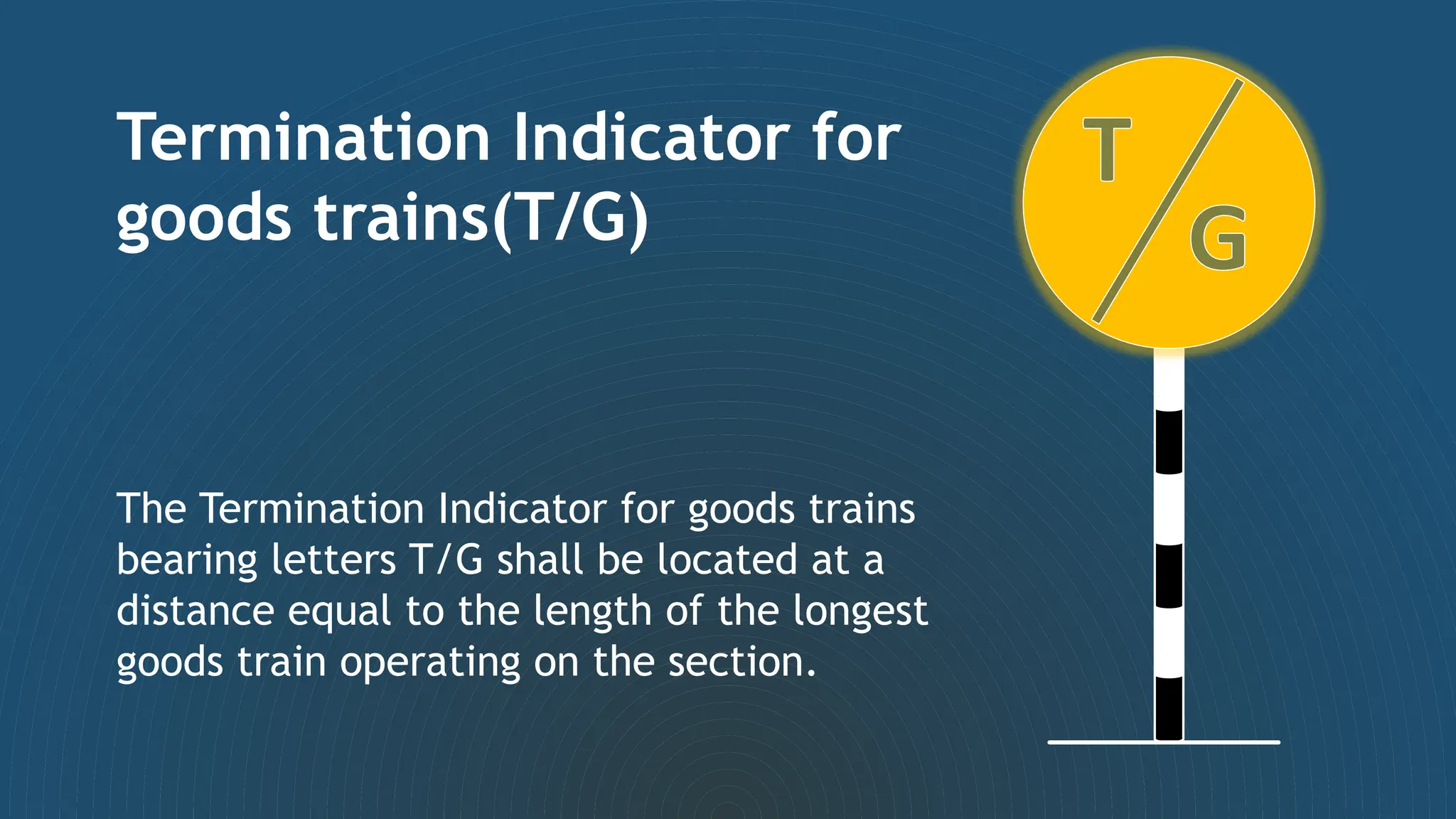
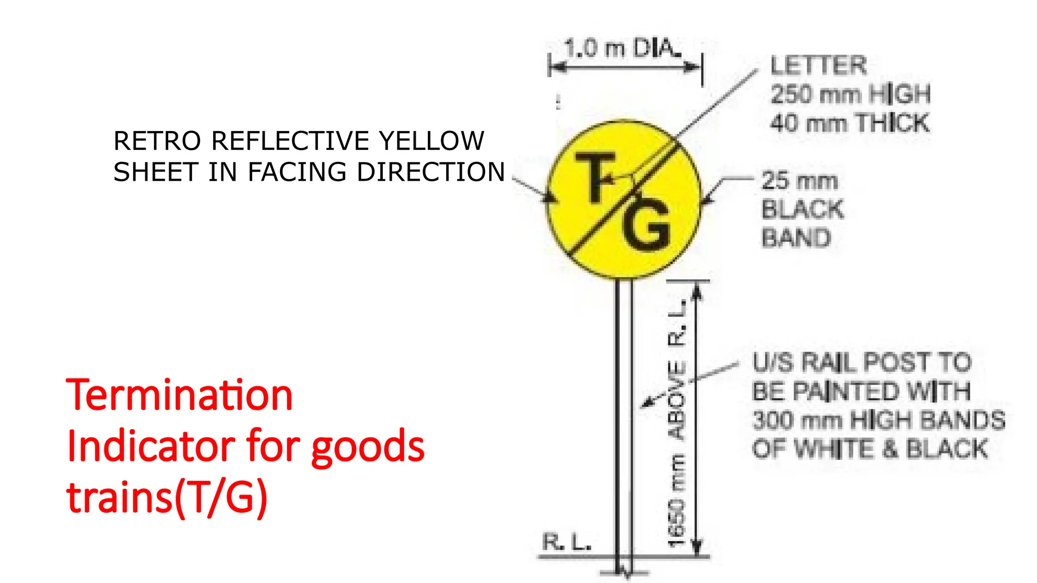
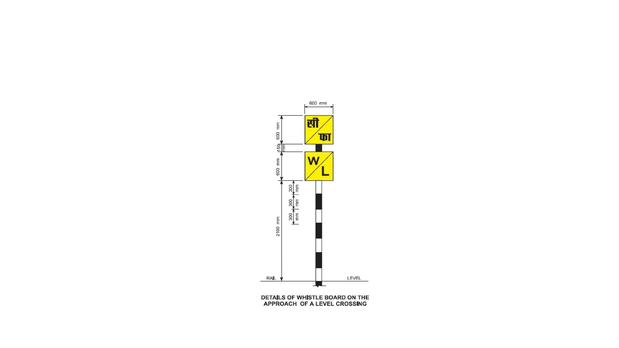
2.3_Engineering Indicators: Temporary and
Permanent.
PERIODS- 4
Engineering indicators
Temporary Engineering indicator:-
(a) Caution indicator.
(b) Speed indicator.
(c) Stop indicator.
(d) Termination indicator for Passenger trains (T/P)
(e) Termination indicator for Goods train (T/G).
Protection of line in block section–
• (a) In case where stop dead restriction is to be imposed when
restriction is to last for more than a day, the following temporary
Engineering indicators should be exhibited at the appropriate
distance–
• (i) Caution indicator.
• (ii) Stop indicator.
• (iii) Termination indicators.
Protection of line in block section–
• (b) In case where the train is not required to stop (non-stop
restriction) and the restriction is likely to last for more than a
day, the following temporary Engineering indicators should
be exhibited at the appropriate distances–
• (i) Caution indicator.
• (ii) Speed indicator.
• (iii) Termination indicators.
Protection of line in block section–
• When during the course of the work, on consideration of
safety it is not desirable to pass trains over the site of work
for the time being, the track should be further protected by
hand signals and banner flags, by the authorised railway
servant.
Caution Indicator
• This board indicates that the line ahead
is under repairs necessitating speed
restriction with the Loco Pilot to be
prepared for either a Speed Indicator or
Stop Indicator ahead.
• This shall consist of a horizontal board
1.4 m, wide by 0.4 m deep fish tailed at
one end .
• This indicator shall be provided both for
permanent and temporary restrictions.
 The Caution Indicator shall
be situated not less than
1200 m for B. G. from the
point, where stoppage is
required.
 The Caution Indicator shall
be situated not less than
800 m for B. G. from the
point, where speed is to be
restricted.
Retro reflective
black sheet in
facing direction
U/S Rail post to be
painted with 300 mm
high bands of
white & black
Caution
indicator
Stop Indicator
• This shall consist of a horizontal board 1.4 m,
wide by 0.4 m and painted with red and
white vertical stripes.
• This indicator will be used when trains are
required to stop.
A stop indicator shall be
exhibited at a distance of 30
m from the place of
obstruction
Stop indicator
U/S RAIL POST TO BE
PAINTED WITH 300
MM BANDS OF
WHITE & BLACK
Stop
indicator
Retro reflective RED
sheet in facing
direction
R. L.
2.0
m
above
R.L.
Speed Indicator
• This shall consist of a yellow equilateral triangular
board with 1.0 m sides, painted yellow and bearing 0.3
m high & 40 mm thick black figures giving the speed at
which a train is to proceed past the indicator.
• The speed indicator shall be provided for both
permanent and temporary restrictions.
A speed indicator shall be
exhibited at a distance of 30
m. from the place of
obstruction
Speed indicator
Speed Indicator
Figures
300 mm. high
40 mm thick
RETRO REFLECTIVE YELLOW
SHEET IN FACING DIRECTION
U/S RAIL POST TO BE
PAINTED WITH 300 MM
BANDS OF WHITE & BLACK
Termination Indicator
• Termination Indicator
• There are two Termination Indicators namely
Termination Indicators for passenger trains(T/P)
and Termination Indicators for goods trains(T/G).
• These shall consist of one m diameter disc.
• Painted yellow and bearing 250 mm high 40 mm
thick letter ‘T/P’ and ‘T/G’ in black .
• These shall indicate the point from which the
normal speed may be resumed.
Termination Indicator for
passenger trains(T/P)
The Termination Indicator for passenger
trains bearing letters T/P shall be located at
a distance equal to the length of the
longest passenger train operating on the
section
Termination Indicator
for passenger trains(T/P)
RETRO REFLECTIVE YELLOW
SHEET IN FACING DIRECTION
Termination Indicator for
goods trains(T/G)
The Termination Indicator for goods trains
bearing letters T/G shall be located at a
distance equal to the length of the longest
goods train operating on the section.
Termination
Indicator for goods
trains(T/G)
RETRO REFLECTIVE YELLOW
SHEET IN FACING DIRECTION
Temporary Engineering Fixed Signals
• For intermediate tracks on triple or multiple lines, Engineering
indicators should be fixed between tracks to within 300 mm from rail-
level, to avoid infringements of standard dimensions.
• All indicators should be placed on the left hand side as seen by the
Drivers except on Centralised Traffic Control (CTC) sections (single
line) where they should be placed on Right hand side.
Location and Details
Temporary Engineering Fixed Signals …
• One termination indicator bearing the letters T/P should be located at
a distance equal to the length of the longest passenger train operating
on the section from the place of work, which will help the passenger
trains to pick up speed after reaching T/P indicator, without losing
time.
• The Guard of a passenger train shorter than the longest passenger
train will exhibit an “all-clear” signal to his Driver when the rearmost
vehicle has cleared the restricted length and the Driver will resume
normal speed.
• In the case of light-engines or single unit rail cars, the Drivers will
resume normal speed after clearing the restricted length.
Location and Details
Temporary Engineering Fixed Signals …
• Another termination indicator bearing letters T/G should be located at
a distance equal to the length of the longest goods trains operating on
the section from the place of work, which will help the goods trains to
pick up speed after reaching T/G indicator, without losing time.
Location and Details
Permanent Speed Restriction Indicators
• Permanent speed restrictions boards–
• Permanent speed restrictions in force are notified in working time-
table.
• The speed indictors are erected to indicate to the Drivers the speed
restrictions to be observed e.g., between stations, and at stations due
to weaker track/bridges, restrictions on curves, grades and points and
crossings etc.
Permanent Speed Restriction Indicators …
• Permanent speed restrictions boards–
• The indicators to be used are similar to those used for temporary
restrictions, namely, caution indicator, speed/stop indicators and
termination indicators (T/P & T/G).
• The details of the indicators and the distance at which they are to be
fixed are the same in both the cases i.e. temporary and permanent.
Permanent Speed Restriction Indicators …
Siding Boards–
When speed restriction has been imposed on account of facing points
of an outlying siding, an ‘S’ marker (a circular board of 1 metre dia.
painted yellow, with 300 mm letter ‘S’ painted in black on it) should be
fixed at the points in addition to the speed and caution boards fixed in
rear of the points.
Where however, the sanctioned speed of the section does not exceed
50 Kmph the speed indicator and the ‘S’ board need not be provided
except where the speed over the points is less than sanctioned speed
of the section.
‘S’ marker should be so fixed that the centre of the board is 2 m above
the rail level.
Permanent Speed Restriction Indicators …
• Board indicating speed over points–
• Where the speed over the points at a station is less than the speed
sanctioned at other stations on the same section, a permanent speed
indicator should be fixed on the first approach signal of the station.
Permanent Speed Restriction Indicators …
• The posts of permanent speed indicator marker boards should be
painted with 300 mm high bands in white and black.
• Where a permanent speed restriction is in force on any intermediate
track on triple or multiple lines, the engineering indicators should be
fixed between tracks to within 300 mm from rail-level to avoid
infringement of standard dimensions.
Indicators (General):
• (1)Where indicators are provided under special instructions to furnish
information to Drivers, these should be in black letters or figures on
yellow back ground.
• (2) Whistle indicator–
• (a) Whistle boards should be provided in rear of all places where the
view of the Drivers is obstructed by cuttings or tunnels or curves and
where it is necessary to give audible warnings of the approach of a
train to those working on the track. The whistle boards are fixed at a
distance of 600 metres.
Indicators (General):
• (b) Whistle indicator for level crossings– Whistle boards are also
provided on the approach of all level crossings, where a clear view is
not obtained. These bear the letters W/L.
• Shunting limit Boards– They are provided at an adequate distance in
advance of the trailing points. This shall consist of 600 mm x 1000 mm
rectangular board painted yellow with a black cross on the top and
words “shunting limit” written in black below it. Its height should be 2
metres from the rail level to the underside of the portion containing
the cross and the post on which it is fixed, painted with 300 mm high
bands in white and black. It should be fitted with a lamp/light
showing white light in both directions.
THANKS

2.3_Engineering, Indicators, Temporary and permanent (1).pptx

  • 1.
    2.3_Engineering Indicators: Temporaryand Permanent. PERIODS- 4
  • 2.
    Engineering indicators Temporary Engineeringindicator:- (a) Caution indicator. (b) Speed indicator. (c) Stop indicator. (d) Termination indicator for Passenger trains (T/P) (e) Termination indicator for Goods train (T/G).
  • 3.
    Protection of linein block section– • (a) In case where stop dead restriction is to be imposed when restriction is to last for more than a day, the following temporary Engineering indicators should be exhibited at the appropriate distance– • (i) Caution indicator. • (ii) Stop indicator. • (iii) Termination indicators.
  • 4.
    Protection of linein block section– • (b) In case where the train is not required to stop (non-stop restriction) and the restriction is likely to last for more than a day, the following temporary Engineering indicators should be exhibited at the appropriate distances– • (i) Caution indicator. • (ii) Speed indicator. • (iii) Termination indicators.
  • 5.
    Protection of linein block section– • When during the course of the work, on consideration of safety it is not desirable to pass trains over the site of work for the time being, the track should be further protected by hand signals and banner flags, by the authorised railway servant.
  • 6.
    Caution Indicator • Thisboard indicates that the line ahead is under repairs necessitating speed restriction with the Loco Pilot to be prepared for either a Speed Indicator or Stop Indicator ahead. • This shall consist of a horizontal board 1.4 m, wide by 0.4 m deep fish tailed at one end . • This indicator shall be provided both for permanent and temporary restrictions.
  • 7.
     The CautionIndicator shall be situated not less than 1200 m for B. G. from the point, where stoppage is required.  The Caution Indicator shall be situated not less than 800 m for B. G. from the point, where speed is to be restricted.
  • 8.
    Retro reflective black sheetin facing direction U/S Rail post to be painted with 300 mm high bands of white & black Caution indicator
  • 9.
    Stop Indicator • Thisshall consist of a horizontal board 1.4 m, wide by 0.4 m and painted with red and white vertical stripes. • This indicator will be used when trains are required to stop.
  • 10.
    A stop indicatorshall be exhibited at a distance of 30 m from the place of obstruction Stop indicator
  • 11.
    U/S RAIL POSTTO BE PAINTED WITH 300 MM BANDS OF WHITE & BLACK Stop indicator Retro reflective RED sheet in facing direction R. L. 2.0 m above R.L.
  • 12.
    Speed Indicator • Thisshall consist of a yellow equilateral triangular board with 1.0 m sides, painted yellow and bearing 0.3 m high & 40 mm thick black figures giving the speed at which a train is to proceed past the indicator. • The speed indicator shall be provided for both permanent and temporary restrictions.
  • 13.
    A speed indicatorshall be exhibited at a distance of 30 m. from the place of obstruction Speed indicator
  • 14.
    Speed Indicator Figures 300 mm.high 40 mm thick RETRO REFLECTIVE YELLOW SHEET IN FACING DIRECTION U/S RAIL POST TO BE PAINTED WITH 300 MM BANDS OF WHITE & BLACK
  • 15.
    Termination Indicator • TerminationIndicator • There are two Termination Indicators namely Termination Indicators for passenger trains(T/P) and Termination Indicators for goods trains(T/G). • These shall consist of one m diameter disc. • Painted yellow and bearing 250 mm high 40 mm thick letter ‘T/P’ and ‘T/G’ in black . • These shall indicate the point from which the normal speed may be resumed.
  • 16.
    Termination Indicator for passengertrains(T/P) The Termination Indicator for passenger trains bearing letters T/P shall be located at a distance equal to the length of the longest passenger train operating on the section
  • 17.
    Termination Indicator for passengertrains(T/P) RETRO REFLECTIVE YELLOW SHEET IN FACING DIRECTION
  • 18.
    Termination Indicator for goodstrains(T/G) The Termination Indicator for goods trains bearing letters T/G shall be located at a distance equal to the length of the longest goods train operating on the section.
  • 19.
    Termination Indicator for goods trains(T/G) RETROREFLECTIVE YELLOW SHEET IN FACING DIRECTION
  • 20.
    Temporary Engineering FixedSignals • For intermediate tracks on triple or multiple lines, Engineering indicators should be fixed between tracks to within 300 mm from rail- level, to avoid infringements of standard dimensions. • All indicators should be placed on the left hand side as seen by the Drivers except on Centralised Traffic Control (CTC) sections (single line) where they should be placed on Right hand side. Location and Details
  • 21.
    Temporary Engineering FixedSignals … • One termination indicator bearing the letters T/P should be located at a distance equal to the length of the longest passenger train operating on the section from the place of work, which will help the passenger trains to pick up speed after reaching T/P indicator, without losing time. • The Guard of a passenger train shorter than the longest passenger train will exhibit an “all-clear” signal to his Driver when the rearmost vehicle has cleared the restricted length and the Driver will resume normal speed. • In the case of light-engines or single unit rail cars, the Drivers will resume normal speed after clearing the restricted length. Location and Details
  • 22.
    Temporary Engineering FixedSignals … • Another termination indicator bearing letters T/G should be located at a distance equal to the length of the longest goods trains operating on the section from the place of work, which will help the goods trains to pick up speed after reaching T/G indicator, without losing time. Location and Details
  • 23.
    Permanent Speed RestrictionIndicators • Permanent speed restrictions boards– • Permanent speed restrictions in force are notified in working time- table. • The speed indictors are erected to indicate to the Drivers the speed restrictions to be observed e.g., between stations, and at stations due to weaker track/bridges, restrictions on curves, grades and points and crossings etc.
  • 24.
    Permanent Speed RestrictionIndicators … • Permanent speed restrictions boards– • The indicators to be used are similar to those used for temporary restrictions, namely, caution indicator, speed/stop indicators and termination indicators (T/P & T/G). • The details of the indicators and the distance at which they are to be fixed are the same in both the cases i.e. temporary and permanent.
  • 25.
    Permanent Speed RestrictionIndicators … Siding Boards– When speed restriction has been imposed on account of facing points of an outlying siding, an ‘S’ marker (a circular board of 1 metre dia. painted yellow, with 300 mm letter ‘S’ painted in black on it) should be fixed at the points in addition to the speed and caution boards fixed in rear of the points. Where however, the sanctioned speed of the section does not exceed 50 Kmph the speed indicator and the ‘S’ board need not be provided except where the speed over the points is less than sanctioned speed of the section. ‘S’ marker should be so fixed that the centre of the board is 2 m above the rail level.
  • 26.
    Permanent Speed RestrictionIndicators … • Board indicating speed over points– • Where the speed over the points at a station is less than the speed sanctioned at other stations on the same section, a permanent speed indicator should be fixed on the first approach signal of the station.
  • 27.
    Permanent Speed RestrictionIndicators … • The posts of permanent speed indicator marker boards should be painted with 300 mm high bands in white and black. • Where a permanent speed restriction is in force on any intermediate track on triple or multiple lines, the engineering indicators should be fixed between tracks to within 300 mm from rail-level to avoid infringement of standard dimensions.
  • 28.
    Indicators (General): • (1)Whereindicators are provided under special instructions to furnish information to Drivers, these should be in black letters or figures on yellow back ground. • (2) Whistle indicator– • (a) Whistle boards should be provided in rear of all places where the view of the Drivers is obstructed by cuttings or tunnels or curves and where it is necessary to give audible warnings of the approach of a train to those working on the track. The whistle boards are fixed at a distance of 600 metres.
  • 29.
    Indicators (General): • (b)Whistle indicator for level crossings– Whistle boards are also provided on the approach of all level crossings, where a clear view is not obtained. These bear the letters W/L. • Shunting limit Boards– They are provided at an adequate distance in advance of the trailing points. This shall consist of 600 mm x 1000 mm rectangular board painted yellow with a black cross on the top and words “shunting limit” written in black below it. Its height should be 2 metres from the rail level to the underside of the portion containing the cross and the post on which it is fixed, painted with 300 mm high bands in white and black. It should be fitted with a lamp/light showing white light in both directions.
  • 32.