Download to read offline
![1N5400-1N5408
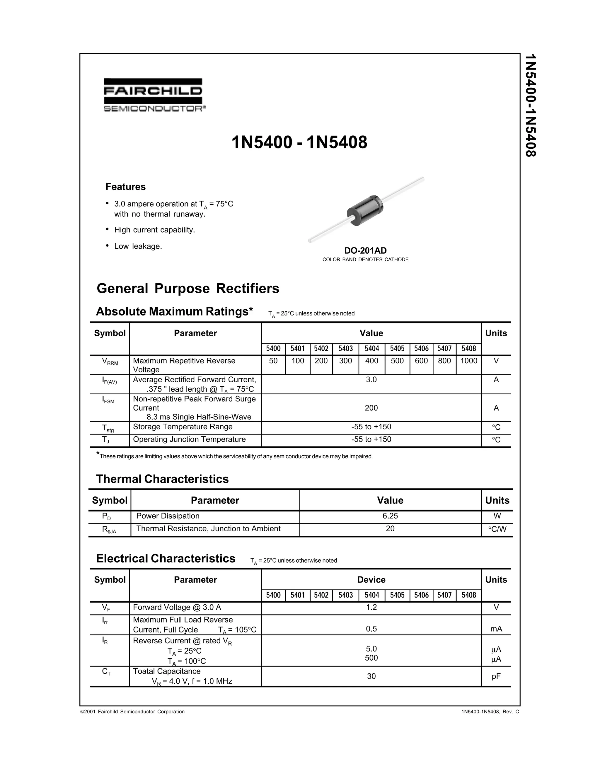
General Purpose Rectifiers
(continued)
Typical Characteristics
Average Rectified Forward Current, IF [A]
4
3
2
1
0
9.5mm LEAD LENGTH
25 50 75 100 125 150 175 200
Ambient Temperature [ºC]
100
10
5
1
0.1
Forward Current, IF [A]
0.01
T J = 25º C
Pulse Width = 200μS
1% Duty Cycle
0.4 0.6 0.8 1 1.2 1.4 1.6 1.8
Forward Voltage, VF [V]
Figure 1. Forward Current Derating Curve
T A = 105 º C
1 2 5 10 20 50 100
Number of Cycles at 60Hz
Figure 3. Non-Repetitive Surge Current Figure 4. Reverse Current vs Reverse Voltage
100
50
10
5
1
Figure 2. Forward Voltage Characteristics
T A = 25 º C
0 20 40 60 80 100 120 140
100
10
1
0.1
Percent of Rated Peak Reverse Voltage [%]
Reverse Current, IR [mA]
0.1 1 5 10 50 100
Reverse Voltage, VR [V]
Total Capacitance, CT [pF]
200
Peak Forward Surge Current, IFSM [A]
160
120
80
40
0
Figure 5. Total Capacitance
2001 Fairchild Semiconductor Corporation 1N5400-1N5408, Rev. C](https://image.slidesharecdn.com/1n5402-140924191232-phpapp02/85/1n5402-2-320.jpg)

This document provides specifications for a series of general purpose rectifier diodes rated from 50V to 1000V. Key specifications include: - Maximum current ratings from 3A up to non-repetitive surge currents of 200A. - Forward voltage drop of 1.2V at 3A current. - Low reverse leakage currents of 5uA to 500uA. - Power dissipation rating of 6.25W and junction temperature range from -55C to 150C. - Total capacitance of 30pF. - Packaging in a DO-201AD case with color bands to denote cathode.


