This document provides specifications for the FGPF70N33BT330V, 70A PDP IGBT including:
- Absolute maximum ratings and thermal characteristics
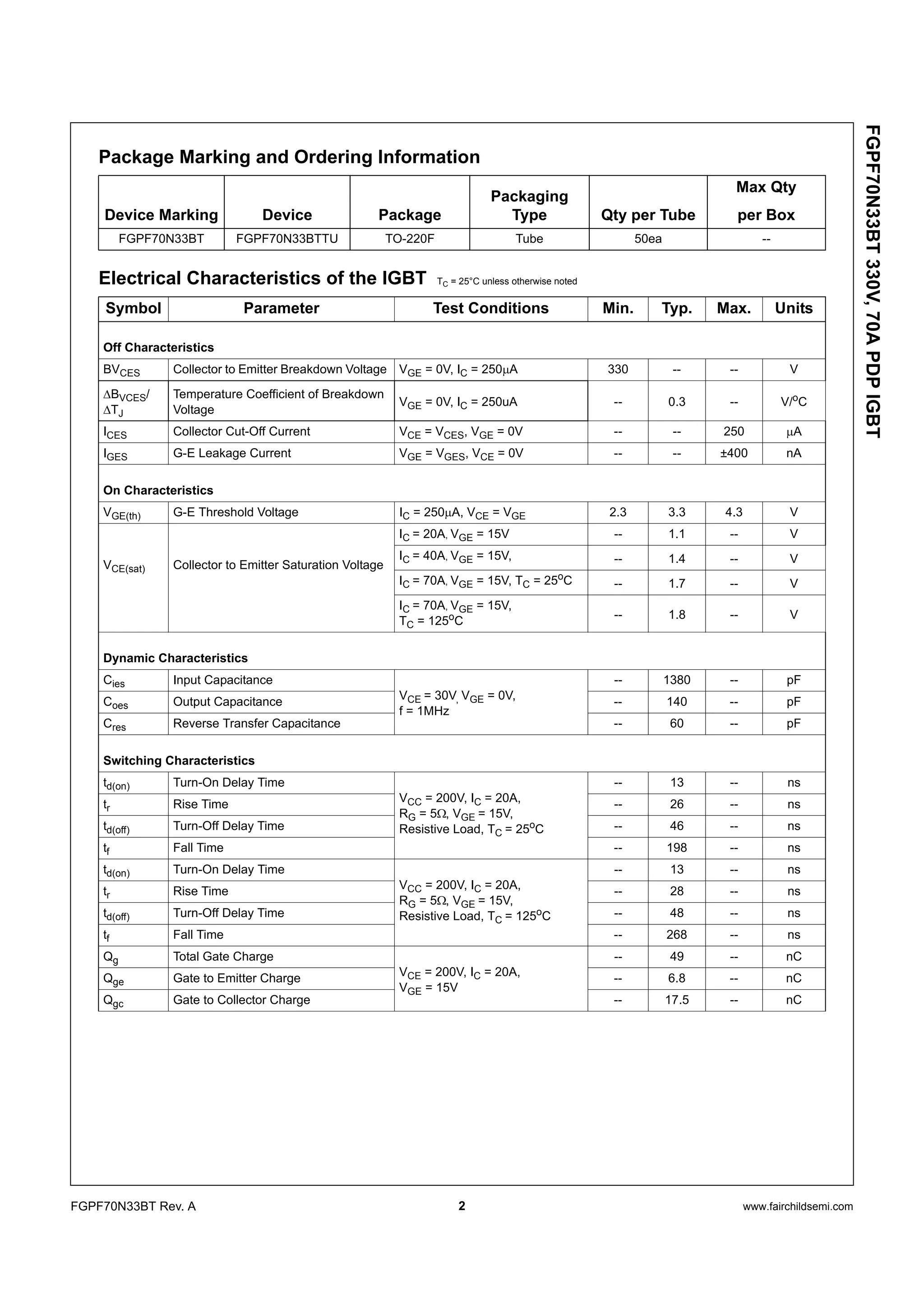
- Electrical characteristics such as saturation voltage, switching times, and gate charge
- Typical performance characteristics graphs for output, saturation voltage, capacitance, switching loss, and safe operating area
- Mechanical dimensions for the TO-220F package
It also includes notes on trademark, counterfeit policy, product status definitions, disclaimer, and life support policy.

![3 www.fairchildsemi.comFGPF70N33BT Rev. A
FGPF70N33BT330V,70APDPIGBT
Typical Performance Characteristics
Figure 1. Typical Output Characteristics Figure 2. Typical Output Characteristics
Figure 3. Typical Saturation Voltage Figure 4. Transfer Characteristics
Characteristics
Figure 5. Saturation Voltage vs. Case Figure 6. Saturation Voltage vs. VGE
Temperature at Variant Current Level
0 1 2 3 4 5
0
44
88
132
176
220
8V
20VTC = 25
o
C
15V
12V
10V
CollectorCurrent,IC[A]
Collector-Emitter Voltage, VCE [V]
0 1 2 3 4 5
0
44
88
132
176
220
8V
20VTC = 125
o
C
15V
12V
10V
CollectorCurrent,IC[A]
Collector-Emitter Voltage, VCE [V]
0 1 2 3 4 5 6
0
44
88
132
176
220
Common Emitter
VGE = 15V
TC = 25
o
C
TC = 125
o
C
CollectorCurrent,IC[A]
Collector-Emitter Voltage, VCE [V]
0 2 4 6 8 10 12 14 16
0
44
88
132
176
220
CollectorCurrent,Ic[A]
Gate-Emitter Voltage, Vge[V]
CommonEmitter
Vce=20V
Tc=25
o
C
Tc=125
o
C
0 4 8 12 16 20
0
4
8
12
16
20
IC = 20A
40A 70A
Common Emitter
TC
= 25
o
C
Collector-EmitterVoltage,VCE[V]
Gate-Emitter Voltage, VGE [V]
25 50 75 100 125 150
0.8
1.0
1.2
1.4
1.6
1.8
2.0
70A
40A
IC = 20A
Common Emitter
VGE = 15V
Collector-EmitterVoltage,VCE[V]
Collector-EmitterCase Temperature, TC [
o
C]](https://image.slidesharecdn.com/gp70n33-200812112023/75/Original-IGTB-GP70N33TBM-A-GP70N33-70N33-TO-220F-New-IXYS-3-2048.jpg)
![4 www.fairchildsemi.comFGPF70N33BT Rev. A
FGPF70N33BT330V,70APDPIGBT
Typical Performance Characteristics
Figure 7. Saturation Voltage vs. VGE Figure 8. Capacitance Characteristics
Figure 9. Gate charge Characteristics Figure 10. SOA Characteristics
Figure 11. Turn-on Characteristics vs. Figure 12. Turn-off Characteristics vs.
0 4 8 12 16 20
0
4
8
12
16
20
70A
IC = 20A
40A
Common Emitter
TC = 125
o
C
Collector-EmitterVoltage,VCE[V]
Gate-Emitter Voltage, VGE [V]
1 10
10
100
1000
10000
Common Emitter
VGE = 0V, f = 1MHz
TC = 25
o
C
Cres
Coes
Cies
Capacitance[pF] Collector-Emitter Voltage, VCE [V]
30
0 10 20 30 40 50 60
0
3
6
9
12
15
Common Emitter
TC = 25
o
C
200V
VCC = 100V
Gate-EmitterVoltage,VGE[V]
Gate Charge, Qg [nC]
0.1 1 10 100 400
0.01
0.1
1
10
100
500
10ms
1ms
Single Nonrepetitive
Pulse TC = 25oC
Curves must be derated
linearly with increase
in temperature
DC
10µs
100µs
CollectorCurrent,Ic[A]
Collector-Emitter Voltage, VCE [V]
0 15 30 45 60
1
10
100
Common Emitter
VCC = 200V, VGE = 15V
IC = 20A
TC = 25
o
C
TC = 125
o
C
td(on)
tr
SwitchingTime[ns]
Gate Resistance, RG [Ω]
200
0 15 30 45 60
10
100
1000
Common Emitter
VCC = 200V, VGE = 15V
IC = 20A
TC = 25
o
C
TC = 125
o
C
td(off)
tf
SwitchingTime[ns]
Gate Resistance, RG [Ω]
Gate Resistance Gate Resistance](https://image.slidesharecdn.com/gp70n33-200812112023/75/Original-IGTB-GP70N33TBM-A-GP70N33-70N33-TO-220F-New-IXYS-4-2048.jpg)
![5 www.fairchildsemi.comFGPF70N33BT Rev. A
FGPF70N33BT330V,70APDPIGBT
Typical Performance Characteristics
Figure 13. Turn-on Characteristics vs. Figure 14. Turn-off Characteristics vs.
Collector Current Collector Current
Figure 15. Switching Loss vs. Gate Resistance Figure 16. Switching Loss vs. Collector Current
Figure 17. Turn off Switching SOA Characteristics
20 30 40 50 60 70
1
10
100
1000
Common Emitter
VGE = 15V, RG = 5Ω
TC
= 25
o
C
TC
= 125
o
C tr
td(on)
SwitchingTime[ns]
Collector Current, IC [A]
20 30 40 50 60 70
1
10
100
1000
Common Emitter
VGE = 15V, RG = 5Ω
TC
= 25
o
C
TC
= 125
o
C
td(off)
tf
SwitchingTime[ns] Collector Current, IC [A]
0 10 20 30 40 50
1
10
100
1000
Common Emitter
VCC
= 200V, VGE
= 15V
IC
= 20A
TC
= 25
o
C
TC
= 125
o
C
Eon
Eoff
SwitchingLoss[mJ]
Gate Resistance, RG [Ω]
20 30 40 50 60 70
1
10
100
1000
Common Emitter
VGE
= 15V, RG
= 5Ω
TC
= 25
o
C
TC
= 125
o
C
Eon
Eoff
SwitchingLoss[mJ]
Collector Current, IC [A]
3000
1 10 100
1
10
100
400
Safe Operating Area
VGE
= 15V, TC
= 125
o
C
CollectorCurrent,IC[A]
Collector-Emitter Voltage, VCE [V]
600](https://image.slidesharecdn.com/gp70n33-200812112023/75/Original-IGTB-GP70N33TBM-A-GP70N33-70N33-TO-220F-New-IXYS-5-2048.jpg)
![6 www.fairchildsemi.comFGPF70N33BT Rev. A
FGPF70N33BT330V,70APDPIGBT
Typical Performance Characteristics
Figure 18.Transient Thermal Impedance of IGBT
1E-5 1E-4 1E-3 0.01 0.1 1 10 100
1E-3
0.01
0.1
1
0.01
0.02
0.1
0.05
0.3
single pulse
ThermalResponse[Zthjc]
Rectangular Pulse Duration [sec]
Duty Factor, D = t1/t2
Peak Tj = Pdm x Zthjc + TC
0.5
t1
PDM
t2](https://image.slidesharecdn.com/gp70n33-200812112023/75/Original-IGTB-GP70N33TBM-A-GP70N33-70N33-TO-220F-New-IXYS-6-2048.jpg)
![7 www.fairchildsemi.comFGPF70N33BT Rev. A
FGPF70N33BT330V,70APDPIGBT
Mechanical Dimensions
TO-220F
(7.00) (0.70)
MAX1.47
(30°)
#1
3.30±0.1015.80±0.20
15.87±0.20
6.68±0.20
9.75±0.30
4.70±0.20
10.16 ±0.20
(1.00x45°)
2.54 ±0.20
0.80 ±0.10
9.40 ±0.20
2.76 ±0.20
0.35 ±0.10
ø3.18 ±0.10
2.54TYP
[2.54 ±0.20]
2.54TYP
[2.54 ±0.20]
0.50
+0.10
–0.05
Dimensions in Millimeters](https://image.slidesharecdn.com/gp70n33-200812112023/75/Original-IGTB-GP70N33TBM-A-GP70N33-70N33-TO-220F-New-IXYS-7-2048.jpg)