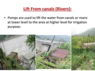
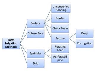
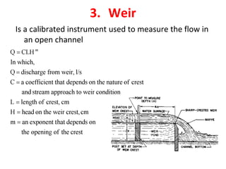
Definition of Irrigation
• The process of artificial application of water to the soil
for the growth of agricultural crop during periods of
inadequate rainfall.
• Is a science of planning and designing, to apply water
artificially to the agricultural land in accordance with the
“crop water requirements” through the “crop period” for
full-fledged nourishment of the crop.
• Adequate quantity and quality of water required in the
root zone of the plant.
Objective of Irrigation
• Supply the water to the soil which Is essential for
germination of seed and growth of the plant
• Cool the soil and surrounding and hence make
the environment more favorable for plant
growth.
• Softness the soil and hence help in tillage
operation
• Washouts or dilutes the salts in the soil
• It enables the application of fertilizer in the soil
• Reduce the adverse effect of frost action on crop.
Necessity of irrigation
• Insufficient rainfall:
• Uneven distribution of rainfall:
• Improvement of perennial crops yield:
• Development of agriculture in the desert areas:
• Insurance of drought:
Advantages of Irrigation
1. Increase in crop Yield:
2. Protection from famine:
3. Elimination of mixed cropping
4. Improvement in cash crops:
5. Prosperity of farmers:
6. Generation of Hydroelectric Power :
7. Domestic and industrial Water Supply:
8. Inland Navigation
9. A forestation
10. Improvement of ground water table.
11. Increase in employment
Demerits of Irrigation
1. Rising of water table:
2. Formation of marshy land and breeding of
mosquitoes.
3. Formation of Dampness:
4. Loss of valuable lands:
Challenges of irrigation Development
in Nepal
• Lack of clear-cut guideline in both the policy and
implementation.
• Storage reservoirs
• Poor farmer
• Large amount of resources required
• Weak institutional capability of concerned
authority.
• Weak symbiotic relationship between agriculture
and irrigation
Sources of Irrigation:
1. Rainfall
2. Surface Water
3. Ground Water
1. Rainfall:
• Rainfall can directly help irrigation by precipitation occurring
over the crop area or indirectly by adding its runoff to the
rivers.
• This runoff is then stored by weir, barrage or dam
downstream or it may replenish as an underground reservoir.
• Direct rainfall is the most helpful for the plant and crop
growth if it occurs in proper amount at proper time .
• But it is unreliable as a source of irrigation water.
• It varies from year to year and it may fall altogether.
• It is irregularly distributed throughout the year as well as
within the same season.
2. Surface Water:
• Surface water include water diverted from the
stream and stored into dams and barrages and then
applied to the land through canals or pumped from
rivers, lakes and canals .
3. Ground Water:
• In terai & valleys, we have enormous ground water reservoirs.
In rainy season, due to rain, most of water seeps into the earth
thus raising the water table in ground.
• This water is then taken out with the help of pumps and tube
wells for irrigation purpose. The areas for which there is no
access of canals, there we can get water for irrigation from
underground sources of water.
Types of irrigation System
1. Gravity Flow or Surface Water Flow Irrigation
2. Reservoir Irrigation
3. Lift Irrigation
Gravity Flow Irrigation
• Is providing water where water flow is
due to gravity, not under any
mechanical means
• Due to gravity water flows from higher
areas to the lower areas
• Silt in the canal water has a manure
value (fertilizing agent).
• most canal irrigation in our country is
gravity irrigation system
• is cheaper and the quality of water is
very good because of the presence of
silt content
Reservoir irrigation
• If the runoff is more than the required amount then
headwork and barrages are constructed to store the water
• A head work consists of a weir, canal head regulator, gate
structure (barrage). So, a headwork is a complete system of
structures. Whereas barrage is a part of a headwork, it is
constructed in the path of the river to obstruct water.
• The flow of a river is seasonal flow. So in order to regulate
the flow the reservoirs are constructed in order to
1. Fulfill the irrigation requirements
2. Generate the hydraulic power
3. Regulate the river flow so as to avoid flood
Lift Irrigation:
• When the main source is at the lower level than the supply level
then we try to supply water by using some mechanical means,
such type of irrigation is known as Lift Irrigation.
• This can be done by the following methods,
(a) Lift from canals
(b)Open Wells
(c) Tube wells
Lift From canals (Rivers):
• Pumps are used to lift the water from canals or rivers
at lower level to the area at higher level for irrigation
purpose.
Open Wells:
• There are some open holes whose depth intercepts
the water table.
• So the water is taken out from lower level to the
surface for irrigation purpose by adopting different
manual and mechanical methods
Tube Wells
• It is the lifting of water by pumping from underground
reservoir.
• Extensive surface irrigation results in an increase in the ground
water level due to percolation and seepage which causes water
logging in large areas. Irrigation by this method will reduce the
yield.
• Tube well irrigation offers a remedial measure by providing
sub-surface drainage.
• Tube well irrigation can be obtained more quickly than from
surface water project.
• Large capital costs involve in canal irrigation for the
construction of dam, canal and headwork system but tube well
construction cost is very less.
Demerits of Irrigation
1. Rising of water table:
2. Formation of marshy land:
3. Formation of Dampness:
4. Loss of valuable lands:
History of Irrigation Development in Nepal
1. Primary phase or the period prior to planned
development, i.e., Before 1956;
2. Infrastructure development phase (1957-1970);
3. Intensive development phase (1971-1985); and
4. Integrated development phase (1986-date).
Primary Phase (Before 1956)
• Irrigation facilities constructed in the Kathmandu valley during
Lichhvi period and Malla period such as Raj Kulos of which the traces
are still found are the oldest ones under primary phase.
• King Ram Shah of Gorkha had special contribution in irrigation
management aspect by empowering local people in irrigation related
dispute resolution.
• During the Rana regime, Chandra Shumsher, with the assistance of
British engineers, had developed Chandra Canal system in 1928.
• The other irrigation facilities during primary phase are- Juddha Canal
in Sarlahi district, Jagadishpur Irrigation system in Kapilvastu district,
Pardi Irrigation system in Pokhara, etc.
• In addition to these, the irrigation systems developed with the
involvement of the State within this period covered 6,228 ha
Infrastructure Development Phase (1957-1970)
• Irrigation facilities developed in 1st, 2nd and 3rd Plan periods fall under
infrastructure development phase.
• Nepal developed different irrigation facilities with the cooperation from
India and USA in this phase.
• Tika Bhairav, Mahadev Khola and Budhanilkantha irrigation systems in
the Kathmandu valley and Vijayapur irrigation system in Pokhara were
developed.
• Likewise, Sirsha, Dudhaura and Tilawe irrigation systems were developed
by the Indian engineers under the financial aid of the USA.
• Khageri (Chitwan), Kamala and Hardinath (Dhanusha), Kodku-Godavari
(Lalitpur), Pahsupati (Kathmandu), Jhanjh (Rautahat) and Tinau
(Rupandehi) are the examples of a few other irrigation systems that can
be cited in infrastructure development phase.
• Apart from these, irrigation systems, which were developed under the
Koshi and Gandak treaties with India, were also constructed during those
three plan periods.
Intensive Development Phase (1971-1985)
• During 4th, 5th and 6th Plan periods, multilateral donor agencies
like the World Bank and the ADB came forward in aid of Nepal in
irrigation development.
• These agencies focused their assistance to convey irrigation water
to farmers’ fields with the canal network development from the
infrastructure already created and to initiate coordination between
irrigation and agricultural agencies, hence the name- intensive
development phase.
• Development of Kankai and Mahakali-I Irrigation Projects, initiation
of command area development in Narayani Zone Irrigation System,
etc., were carried out with these agencies’ assistance.
• During these plan periods, CARE Nepal had assisted to develop a
number of small irrigation systems covering a total of 10,000 ha.
• Bhairawa-Lumbini Groundwater, Marchawar Lift and Hill Irrigation
Projects were also initiated in this intensive development phase.
Integrated Development Phase (1986-date)
• From the 7th Plan onward, i.e., since the mid eighties, there has been a
major paradigm shift in irrigation development.
• Construction oriented development has been given less importance and
new dimensions- such as farmers’ participation through organised
associations, rehabilitation of farmers’ canals, management transfer, etc.,
have been given more and more attention.
• Leaving Bagmati, Babai, Mahakali-II and Sikta Irrigation Projects aside, no
other major projects were taken up.
• Rehabilitations of small farmers’ canals were given high priority under
sectoral approach.
• Irrigation Sector Projects were implemented and the ongoing Community
Managed Irrigated Agriculture Support Project is being implemented in
Central and Eastern regions under the assistance of ADB.
• The World Bank version of these projects implemented in the remaining
three western regions are Irrigation Line of Credit Project, Nepal Irrigation
Sector Project and the IWRMP.
Irrigation Status of Nepal
Of 1,766,000 hectares of irrigable land in Nepal served
by surface irrigation system (DoI, 2017), only 70% of
the command area is actually irrigated and only 38%
of this irrigated land has year-round service (CIP,
2012).
Water resource potential of Nepal
• Nepal has abundant water resources, with annual discharge
of total 150 billion m3, and capable of irrigating 6-8 MT/ha.
• Hydropower potential is 83000 MW.
• Out of this, 45610 MW have been identified as economically
feasible (WECS 2011)
• Less than 8% of the country’s water potential is used for
irrigation (WECS, 2011)
• Avg. annual precipitation - 1530 mm
• Total surface water - 220 billion m3
Farm Water Management
Field water losses
IRRIGATION EFFICIENCY:
• The ratio of the amount of water available (output) to the
amount of water supplied (input) is known as Irrigation
Efficiency. It is expressed in percentage.
The following are the various types of irrigation efficiencies,
(a) Water Conveyance Efficiency
(b) Water Application Efficiency
(c) Water Storage Efficiency
(d) Water Distribution Efficiency
Water Conveyance Efficiency
• It is the ratio of the amount of water applied to the
land, to the amount of water supplied from the
reservoir.
• It is obtained by the expression,
Where,
Water Application Efficiency
• It is the ratio of the water stored in root zone of plants
to the water applied to the land.
• It is obtained by the expression,
• Where,
Water Storage Efficiency
Water Use Efficiency
• It is the ratio of the amount of water beneficially used
(including leaching) to the amount of water applied.
• It is obtained by the expression,
Where,
Water Distribution Efficiency
numerical
• Stream 135lit/sec was diverted from a canal and 100
lit/sec was delivered to the field. Area of 1.6 ha was
irrigated in 8 hours. The effective depth of root zone
was 1.8m. The runoff loss in the field was 432m3. the
depth of water penetration varied linearly from 1.8m
at the head of the field to 1.2m at the tail end.
Available moisture holding capacity of soil is 20cm/m
depth of soil. Irrigation was started at 50% depletion of
available soil moisture. Determine water conveyance
efficiency, water application efficiency, water
distribution efficiency and storage efficiency.
Base period, duty and delta
1. Duty of water: is the relation between the area of the land
irrigated and the quantity of water required.
• Duty (D) is defined as the area of the land, which can be irrigated if
one cumec (m3/sec) of water was applied to the land continuously
for the entire base period of the crop and it is expressed in
hectares/cumecs.
2. Base period (B): is the period between the first watering and the
last watering.
• The base period is slightly different from the crop period, which is
the period between the time of sowing and the time of harvesting
the crop.
Base period, duty and delta
3. Delta (∆): is the total depth of water required by a crop during
the entire base period. If the entire quantity of applied water
were spread uniformly on the land surface, the depth of water
would have been equal to delta.
• Thus the delta (in m) of any crop can be determined by dividing
the total quantity of water (in ha-m) required by the crop, by the
area of the land (in ha).
• Delta (∆) = Total quantity of water (ha-m)
• Total area of land (ha)
Relation Between Duty, Base Period And Delta
Considering the area of land of D-hectares and if Duty is expressed in
ha/cumecs the total quantity of water used in the base period of B
days is equal to that obtained by a continuous flow of 1 cumec for
B days.
Quantity of water= 1*B*24*60*60*, m3 -------------------------- (a)
If Delta (∆) is the total depth of water in meters supplied to the land of
D- hectares, the quantity of water is also given by:
Quantity of water = (D *104)* ∆ m3 ------------------------------ (b)
Equating the volumes of water given in eqns (a) and (b)
1*B*24*60*60* = (D*10 4)* ∆
Where D = in ha/cumec
∆ = in m
B = in days
Factors affecting Duty
Duty of water depends up on different factors. In general, the
smaller the losses, the greater are duty because one cumec of
water will be able to irrigate larger area.
• Type of soil
• Type of crop and base period
• Structure of soil
• Slope of ground
• Climatic condition
• Method of application of water
• Salt content of soil
Counteracting all the factors that decrease the duty by decreasing
various losses, may improve duty of water.
Number of Watering:
• The total depth of water required by a crop is not applied at
one time but it is supplied over the base period by stages
depending upon requirement,
• these numbers of stages are known as “Number of Watering”
• Paleo:
• The initial watering which is done on the land to provide
moisture to the soil just before sowing any crop is known as
paleo or paleva.
Kor Watering & Kor Period:
Kor Watering:
• The first watering which is done when the crop has
grown to about three centimetres is called Kor
Watering.
Kor Period:
• The portion of the base period in which Kor watering is
needed is called “Kor Period”
Cumec Day:
• The quantity of water flowing continuously for one
day at the rate of one cumec is known as cumec
day.
Command area of irrigation system
– GCA, CCA and NCA
Gross Command Area (G.C.A):
The whole area enclosed between an imaginary boundary lines which can be included
in an irrigation project for supplying water to agricultural land by the network of
canals is known as Gross command Area (G.C.A). It includes both the culturable
and unculturable areas.
Mathematically,
Unculturable Command Area (Un-C.C.A):
The area where the agriculture cannot be done and crops cannot be grown is known
as unculturable area. The marshy lands, lakes, ponds, forests, villages etc are
considered as unculturable.
Culturable Command Area (C.C.A):
The total area within an irrigation project where the cultivation can be done and crops
can be grown.
Mathematically,
Intensity of Irrigation:
• It is defined as the ratio of cultivated land for a particular crop
to the total C.C.A. It is expressed as % of C.C.A.
• For example, if the total C.C.A is 1000 hectares where wheat
is cultivated in 250 hectares
• Then,
Area to Be Irrigated:
It is the product of C.C.A and the intensity of irrigation.
Mathematically,
Time Factor:
• The ratio of the number of days the canal has actually been
kept open to the number of days the canal was designed to
remain open during the base period is known as time factor.
• Mathematically,
• For example, a canal was designed to kept open for 15 days,
but it was practically kept open for 10 days for supplying water
to the culturable area, then the time factor is 10/15 = 0.667
Capacity Factor:
• It is the ratio of the average discharge to the maximum
discharge (design discharge).
• Mathematically,
• For example, a canal was designed or the maximum discharge
of 50 cumecs, but the average discharge is 40 cumecs, then
the capacity factor is 40/50 = 0.8
Irrigation frequency/irrigation interval
• No of day between two irrigations during
periods without rainfall.
• Irrigation Period:
Farm Water Management
6.Farm Irrigation Methods
Farm
Irrigation
Methods
Surface
Uncontrolled
flooding
Border
Check Basin
Furrow
Deep
Corrugation
Sub-surface
Sprinkler
Rotating
head
Perforated
pipe
Drip
Surface Irrigation Methods
• Refers to a broad class of irrigation in which the soil
surface conveys and distributes water over the
irrigated field and at the same time infiltrates into the
underlying profile.
• Is the oldest and still the most widely used method of
water application to agricultural land.
Advantages of surface irrigation
• It is more acceptable to agriculturalists that appreciate the
effect of water shortage on crop yield since it appears easier
to apply the depth required to fill the root zone
• It can be developed at the farm level with minimal capital
investment
• The major capital expense of the surface irrigation system is
generally associated with land grading
• Energy requirements for surface irrigation systems come
from gravity
• Are less affected by climatic and water quality characteristics.
• Is highly flexible, relatively easily managed method of
irrigation.
Disadvantages of surface irrigation
• There is one disadvantage of surface irrigation that
confronts every designer and irrigator.
• “very difficult to define the primary design variables,
discharge and time of application, due to the highly
spatial and temporal variability of the soil”.
Classification of surface Irrigation
Methods
• Flooding
• Basins
• Borders
• Furrows
a) Free flooding
a) Free flooding
➢Water is applied from field ditches without any levee to guide
its flow.
➢Ditches are excavated in the field.
➢Movement of water is not restricted, it is sometimes called
“wild flooding”.
➢It is suitable for close growing crops, pastures etc.
➢It is practiced large where irrigation water is abundant and
inexpensive.
➢It involves low initial cost of land preparation, extra labor
cost in the application of water.
➢Application of efficiency is low.
➢This method may be used on rolling land (topography
irregular) where borders, checks, basins and furrows are not
feasible.
b) Border strip Method
b) Border flooding
➢The farm is divided into a number of strips (width 10 ~ 20 m and
length 100 ~ 400 m) separated by low levees or borders.
➢Water is turned from the supply ditch into these strips along which a
flow slowly toward the lower end, wetting the soil as it advances.
➢When the advancing water front reaches the lower end, the stream
turned off.
➢The surface is essentially level between levees and lengthwise slope
is somewhat according to natural slope of the land (0.2 ~ 0.4%).
➢It is suitable to soils having moderately low to moderately high
infiltration rates and to all closely growing crops.
➢Uniform distribution and high water application efficiencies are
possible.
➢Large streams can be used efficiently.
➢It involves high initial cost.
➢Ridges between borders should be sufficiently high
General types:
➢Straight border
➢Contour border
Advantages:
➢High efficiency can be achieved
➢Utilize large water streams safely
➢Provide uniform wetting and efficient use of water
➢Requires less labour and time
Disadvantages:
➢Large supply of water is needed
➢Requires proper leveling
➢High initial cost
C) Check flooding
C) Check flooding
➢In this method, the entire field is divided into a number of
almost leveled plots surrounded by levees. Water is admitted
from the farmer’s watercourse to these plots turn by turn.
➢Water is applied into relatively leveled plots surrounded by
small levees called check basin.
➢In this method, the check (land) is filled with water at a fairly
high rate & allowed to stand until the water infiltrate.
➢Check flooding is similar to free flooding except that the water
is controlled by surrounding the area with low and flat levees.
Levees are generally constructed along the contours of vertical
interval 5-10 cm.
➢This method is suitable for both permeable and impermeable
soil.
C) Check flooding…
Advantages:
➢Reduces percolation loss in case of more permeable soil as
water can spread quickly.
➢Sometimes, levees are made sufficiently wide so that some
‘row’ crops can be grown over the levee surface
➢Unskilled labour can be employed.
Disadvantages:
➢Nos. of labour required is high.
➢Loss of cultivable area which is occupied by the levees.
➢Levees impose restriction in the use of farm machinery.
d) Basin flooding
➢Basins are flat areas of land surrounded by low bunds. The
bunds prevent the water from flowing to the adjacent fields.
➢The basins are filled to desired depth and the water is
retained until it infiltrates into the soil. Water may be
maintained for considerable periods of time
➢A special type of check flooding.
➢Adopted specially for orchard trees.
➢One or more trees are generally placed in the basin and
surface is flooded.
d) Basin flooding
General Types:
➢Check basin
➢Ring basin
Advantages:
➢Provides efficient use of water
➢Involves less labour and less water
Disadvantages:
➢Requires expert levelling and layout
➢High initial cost
➢Large quantity of water is needed
e) Furrow irrigation
➢Furrows are narrow field fitches excavated between the
rows of plants.
➢Furrows vary from 8-30 cm deep and as much as 400 m
long.
➢Only one-fifth to one-half of the land surface is wetted
by water, as a result there is less evaporation.
➢This methods is suitable for row crops like potatoes,
maize, cotton, etc. and those crops that cannot stand
water for long periods, like 12 to 24 hours.
➢Furrow irrigation is suitable to most soils except sandy
soils that have very high infiltration water and provide
poor lateral distribution water between furrows.
Design of Furrow
es
ngth, metr
furrow le
L
res
acing, met
furrow sp
w
hours
ed time),
ion (elaps
of irrigat
duration
t
ze, lps
stream si
q
d, cm
ter applie
epth of wa
average d
d
In which,
w*L
*t
q*
d
=
=
=
=
=
=
360
%
as
expressed
furrow
of
slope
s
lps
stream,
erosive
-
non
maximum
q
In which,
s
0.6
q
m
m
=
=
=
e) Furrow irrigation…
Advantages:
➢Evaporation loss is reduced
➢High water efficiency
➢Not expansive to maintain
➢Relatively easy to install
➢Labour requirement in land preparation and irrigation are
reduced.
Disadvantages:
➢Requires skills labour for developing furrows
➢Silts from furrow should be removed regularly
Surface Irrigation Processes (hydraulic phases)
• Advance phase: the time interval between the start of irrigation and
arrival of the advancing (wetting) front at the lower end of the field.
• Ponding (wetting storage or continuing) phase: the irrigation time
extending between the end of advance and inflow cut-off.
• The term “Wetting” phase is usually used for furrow and border
where tail water runoff can occur, whereas ponding is the preferred
term for basin irrigation (no tail water runoff)
• Depletion (vertical recession) phase: the time interval between
supply cut-off and the time that water dries up at the inlet boundary.
• Recession (horizontal recession) phase: the time required by the
water to recede from all points in the channel, starting from the end
of the depletion phase.
• The time difference at each measuring station between the clock
time or cumulative time for advance and recession is the
opportunity time, T, infiltration to occur.
Phase of irrigation systems
f) Drip Irrigation
f) Drip Irrigation
➢Involves the slow application of water, drop by drop to
the root-zone of a crop.
➢ Consists of a pumping unit, pipelines with drip type
nozzles or emitters, and a filter unit to remove the
suspended impurities in the water.
➢ Particularly suited to areas where water quality is
marginal, land is steeply sloping or undulating and of poor
quality, where water or labour are expensive, or where high
value crops require frequent water applications.
➢The amount of water dripping from the nozzles can be
regulated, as desired, by varying the pressure at the
nozzles, and the size of the orifice of the nozzles.
➢Water supply may be continuous or intermittent.
f) Drip Irrigation…
A typical drip irrigation system consists of the following
components:
• Pump unit • Control Head
• Main and sub main lines • Laterals
• Emitters and drippers
#Pipe network
-It consists of main line and no. of laterals line.
-Nos. of small diameter pipes called trickle lines are
provides which takes water from lateral pipes and carry it
to the root of crops.
#Emitters
- They are provided on each trickle line at suitable spacing.
Design of Drip Irrigation System
)
Q
(i.e.,
irrigated
area
in the
(n)
plants
of
number
by the
(Q)
system
drip
the
of
capacity
the
dividing
by
estimated
be
can
)
(Q
plant
per
required
discharge
The
hrs
in
irrigation
each
of
Duration
t
fraction)
(in
efficiency
n
applicatio
Water
η
days
interval
Irrigation
T
litre
t,
requiremen
r
Daily wate
V
lph
system,
drip
of
Capacity
Q
In which,
)
*
η
(
*
V
Q
p
p
a
d
a
d
n
Q
t
T
=
=
=
=
=
=
=
f) Drip Irrigation…
Merits/Advantages:
➢Very economic.
➢Surface evaporation is reduced.
➢Suited to arid regions.
➢Can be used for applying fertilizers.
➢Increase yield by 20-50%.
Demerits/Disadvantages:
➢Initial cost is more and
➢Require high maintenance
Sprinkler method
• Applying water to the surface of the soil in the form of a spray,
which is similar to natural rainfall.
• Was started at about 1900.
• Before 1920 sprinkling was limited to tree crops, nurseries and
orchards.
• Most of these systems were stationary overhead-perforated pipe
installations or stationary over tree systems with rotating
sprinklers.
• These systems were expensive to install but often fairly
inexpensive to operate.
• Portable sprinkler systems developed with the introduction of
light weight steel pipe and quick couplers in the early 1930’s,
resulted in reduction of equipment cost and increased number of
sprinkler installation.
Sprinkler method
• Sprinklers have been used on all soil types and on lands
of widely different topography and slopes and for many
crops.
• Water is distributed through a system of pipes usually by
pumping.
• It is then sprayed into the air through sprinklers so that it
breaks up into small water drops, which fall to the
ground.
• The pump supply system, sprinklers and operating
conditions must be designed to enable a uniform
application of water.
Sprinkler irrigation Vs Surface irrigation
• Sprinkler systems can be designed so that less interference
with cultivation and other farming operations occurs, and
less land is taken out of production than with surface
methods.
• Frequent and small depth of water can readily be applied by
sprinkler systems.
• Higher water application efficiency can normally be
obtained by sprinkler irrigation.
• For areas requiring in frequent irrigation, sprinkler
irrigation can be provided at a lower capital investment per
acre of land irrigated than can surface irrigation.
• Whenever water can be delivered to the field under gravity
irrigation, sprinkler irrigation is particularly attractive.
Limitations of sprinkler irrigation
• Wind distorts sprinkler pattern and causes uneven
distribution of water
• Ripened soft fruits may be affected by spraying water
• Water must be clean and free of sand, debris and large
amount of dissolved salts
• High initial investment as compared to surface irrigation
• High power requirements
• Fine textured soils with slow infiltration rate cannot be
irrigated efficiently in hot windy areas
• In areas of high temperature and high wind velocity,
considerable evaporation losses of water may take place
Types of sprinklers and sprinkler
systems
• Based on the arrangement for spraying
irrigation water sprinklers
– Fixed Nozzle
– Perforated sprinkler
– Rotating sprinklers
Continue…
• Based on the method of developing pressure
– Pump powered system
– Gravity sprinkler system
– Hybrid systems (Pumps + Gravity)
• Based on portability and make-up of units
– Portable systems
– Semi Portable Systems
– Permanent system
Components
• Pressure generating units (Pump unit)
• Water carrier units (Mainlines, sub mainlines, Laterals)
• Water delivery units (Riser pipes and Sprinklers)
• Quality improvement sub units (Screens, Desilting-
basins)
• Ancillary units (Fertilizer and other chemical applicator)
Sprinkler Selection and Spacing
cm/hr
rate,
n
applicatio
optimum
I
metres
main,
the
along
lateral
of
spacing
S
metres
laterals,
the
along
sprinklers
of
pacing
S
lps
sprinkler,
individual
of
discharge
required
q
In which,
360
I
*
*
S
q
m
=
=
=
=
=
s
S
l
m
l
%
,
efficiency
n
applicatio
water
E
day
per
hours
operating
actual
of
number
H
irrigation
one
of
completion
for the
allowed
days
of
number
F
cm
n,
applicatio
water
of
depth
net
d
ha
irrigated,
be
to
area
A
lps
pump,
the
of
capacity
discharge
Q
In which,
E
*
H
*
F
d
*
A
2780
Q
=
=
=
=
=
=
=
Sub-surface Irrigation
• A method of providing water to plants by raising the water table to
the root zone of the crop or by carrying moisture to the root zone
by perforated underground pipe.
• In sub surface Irrigation , effluent is delivered directly to
the infiltrative surface of the soil using specially
manufactured polyethylene tubing with built-in turbulent
flow emitters.
Advantage
• Subsurface irrigation is a highly-efficient
watering technique.
• It reduces outdoor water use by 30 to 40
percent
Design
• It consist a masonry chamber (Distribution box) where
the effluent of septic tank uniformly distributed an underground
network.
• Emitter lines placed on 2 foot centers with a 2 foot emitter
spacing such that each emitter supplies a 4 sq. ft area.
• These lines are placed at depths of 6-10 inches below
the surface.
• Absorption trench 30 to 90cm wide filled with gravel(15cm thick)
layer and well graded aggregate(15cm thick layer).
Working
• Septic tank effluent is allowed to enter into a masonry
chamber (distribution chamber).
• from where it is uniformly distributed an underground
network of open jointed pipe ,into absorption trench
called dispersion trenches .
• The suspended organic matter present in the effluent
will be absorbed in the absorption trenches.
• The clearer water seeping down to the water-table
may come up to the plant roots thoroughly capillarity,
thus fulfilling their irrigation water
Numerical
• Furrow of 100 m long and spaced 60 cm apart are
irrigated by an initial furrow stream of 2.5 l/s. the
duration of the initial stream is 30 mins. The size of the
stream was reduced to 1.5 l/s. the cut back stream
continued for 2 hr . Estimate the average depth of
irrigation.
• Furrow 110 m long and spaced 90 cm apart and having
a slope of 0.2% are irrigated for 45 mins by an initial
stream size equal to the maximum non- erosive
stream. The stream size is then reduced to the half and
continued for 1 hr 20 mins. Determine the average
depth of water.
Farm Water Management
8. Open Channel and Management of
Irrigation Water 3 hours
Irrigation System
• The construction of weir or barrage across a river
(known as diversion head works).
• The construction of dam across a river valley (to form a
storage reservoir).
• The excavation of canal system (Network of canals to
cover the command area).
Components
1. Dam /Barrage/Weir
2. Head regulator
3. Main canal
4. Branch Canal
5. Distributary canal
6. Minor canal
7. Water course
Types of Canal
Based on discharge
(a) Main canal
(b) Branch canal
(c) Distributary channel
(d) Field channel
Types of canal
• Based on Soil
a) alluvial canal, and
b) non-alluvial canal
• Based on alignment
a) Ridge or Watershed Canal
b) Contour Canal
c) Side Slope Canal
Free board
• Is the distance between the full supply level and top
of the bank. The amount of free board varies upto
0.6 m - 0.75 m.
• It is provided to keep a sufficient margin so that the
canal water does not overtop the bank in case of
heavy rainfall or fluctuation in water supply.
Side slope
• The side slopes of the canal bank and canal section
depend on the angle of repose of the soil existing on
the site.
• So to determine the side slopes of different sections,
the soil samples should be collected from the site
and should be tested in the soil testing laboratory.
Alignment of canals
Following important points are to be considered:
• It must cover the entire area proposed to be
irrigated.
• Smallest possible length of the canal for economy,
smaller head loss due to friction and smaller loss in
seepage and evaporation.
• There should be less number of cross drainage
structure as far as possible
(i) Contour Canal
• Canal aligned nearly parallel to the contour is called
Contour Canal.
• Culturable area lies on one side.
• Can irrigate only one side. As one of the banks is on the
higher side
• Only a bank is required to construct on the lower side.
• is sometimes called single bank canal.
(ii) Ridge or Watershed Canal
• The canal is aligned along a natural watershed,
known as ridge.
• These canals usually take off from the contour canal.
• It irrigates on both sides.
• Cross Drainage can be avoided and hence it is more
economical.
(iii) Side Slope Canal
• Is aligned roughly perpendicular to contour of the
contour.
• Construction of Cross Drainage Works (CDWs) does
not arise.
• Slope of this canal is steep, which is not essential for
unlined canal.
• It irrigates only on one side just like contour canal.
Design of Open Channels
Definitions
• Wetted perimeter (P) = b+c+c
⮚b = bottom width of the channel
⮚c = wetted sides of the channel
• Area of cross-section (A) = h*(b+T)/2
⮚d = depth of flow of channel
⮚t = width of surface when the water is at depth d
• Hydraulic radius (R) = A/P
• Hydraulic slope (S) = d/l
⮚d = vertical drop of channel for length l
Calculation of Mean Velocity
Numerical Problem
• A Trapezoidal channel is to be constructed for a discharge
of 140 lit/ sec on a bed slope of 0.04%. The side slope of
the channel is 1:1. calculate the dimension of the
trapezoidal channel for the best hydraulic section and
decide whether suitable or not. Assume the depth of
water 35cm and free board is 5cm, also if the discharge is
to increase to 200lit/sec keeping the same section but
only by increasing the velocity. What should be the bed
slope of channel to have suitable section. (say n= 0.01)
• A trapezoidal canal section has to be excavated through
hard clay at the least cost. Determine the dimension of
the channel given that discharge is equal to 15 m3/sec,
bed slope 1:2000, n=0.02
Water Control Structures
• Check gates
• Turnouts
• Division boxes
• Inverted Syphon
• Culverts
• Flumes
• Drop Structures
• Chute Spillway
Check gates
• is a structure used to maintain or increase water level in an open
channel
• is placed in an irrigation channel to form an adjustable dam to
control or rise the elevation of the water surface upstream by at
least about 8 to 12 cm above ground surface so as to use siphon
tubes or turnouts for water diversion from channel to field
efficiently
Turnouts
• are constructed in the bank of a canal to divert part of the
water from the canal and ditches to basins, borders, and
distribution laterals
• can be concrete structures or pipe structures
• may have a fixed opening in the side and equipped with the
device to control the area of opening
• usually have removable flashboards or a circular or
rectangular slide gate to regulate flow
Division boxes
• are used to divide or direct the flow of water between
two or more canals or ditches
• Water enters the box through an opening on one side
and flows out through openings on the other sides.
• These openings are equipped with gates
Syphon Tubes
• are curved plastic, rubber or aluminum pipes that
are laid over the bank of delivery channels to deliver
water to borders and furrows
• are completely filled and dipped into water
• water flows into the tube, is pulled (siphoned) over
the bank of the delivery channel, and delivered into
borders and furrows when there is sufficient
operating head and the tube is properly positioned
and full of water
Inverted Syphon
• is constructed when a channel has to cross a
wide depression or where the road surface
lies close to the field surface
• has an inlet and an outlet tank connected
together at their bottom by a pipe
Culverts
• Is a drain or pipe that allows water to flow under a road
• Are most suitable structures at the channel crossing
when the road fill is sufficiently high and the channel
bed lies on the field surface on either side
• About 45 cm soil cover is desired above the culvert pipe
Flumes
• are constructed to carry irrigation water
across streams, canals, gullies, ravines or
other natural depressions
• may be open channels or pipes which are
often supported by pillars or may be fixed to
bridges
Drop Structures
• is used for conveying water in the channel from
higher elevation to lower elevation while
controlling the energy and velocity of the water
as it passes over
• are needed in canals and ditches to convey water
down steep slopes at non-erosive velocities
Chute Spillway
• are used to convey water from steep slopes
• are lined, high-velocity open channels
• are constructed with concrete, bricks or cement
• have an inlet, a steep-sloped section of lined canal
where the elevation change occurs, a stilling pool or
other energy dissipation device, and an outlet section
Measurement of Irrigation water
1. Volumetric Method
2. Velocity Area Method
i. Float Method
ii. Current meter
3. Weirs
4. Flumes
5. Orifices
1. Volumetric Method
• is suitable for measuring small irrigation stream
• water is collected in a container of known volume and
the time taken to fill the container is recorded
2. Velocity Area Method
i. Float Method
• Is inexpensive and simple
• Measures surface velocity
• Is obtained using a correction factor
3. Weir
Is a calibrated instrument used to measure the flow in
an open channel
Weir
Advantages of Weirs
a) Capable of accurately measuring a wide range of flows
b) Can be both portable and adjustable
c) Easy to construct
d) provide more accurate discharge rating than flumes and
orifices
Disadvantages of Weir
a) Relatively large head required
b) The upstream pool must be kept free of weeds and trash.
Classification of Weirs
Sharp-Crested Weir
• Rectangular Weir
• Cipoletti Weir or Trapezoidal Weir
• V -Notch Weirs or Triangular Weir
Broad-crested Weirs
• has a horizontal or nearly
horizontal crest sufficiently long
in the direction of the flow so
that the nappe will be supported
and hydrostatic pressures will be
fully developed for at least a
short distance
Rectangular Weir
• Takes its name from the
shape of its notch
• Discharge through a weir
or notch is directly related
to the water depth (H)
• Is affected by the
condition of the crest, the
contraction, the velocity of
approaching stream and
the elevation of the water
surface downstream from
the weir.
• Can be suppressed,
partially contracted, or
fully contracted
Contracted Weir
• Sides and crest of a weir are far away from the sides and bottom
of the approach channel.
• The nappe will fully contract laterally at the ends and vertically at
the crest of the weir.
• Also called an “unsuppressed” weir
• For one side contracted
• For two sides contracted
Suppressed Weir
• notch or opening sides are coincident with the sides of the
approach channel, which extend unchanged downstream from
the weir
Cipoletti Weir or Trapezoidal Weir
• Is trapezoidal in shape
• Slope of the sides, inclined outwardly from the crest,
should be one horizontal to four vertical (1H:4V)
• The selected length of notch (L) should be at least 3H
and preferably 4H or longer.
• Considered fully contracted
V -Notch Weirs or Triangular Weir
• the notch is “V” in shape
• Depth of water above the bottom of the V is called head (H)
• The V-notch design causes small changes in discharge hence
causing a large change in depth and thus allowing more
accurate measurement than with a rectangular weir.
• Head (H) should be measured at a distance of at least 4H
upstream of the weir.
4. Parshall flume
• Are devices for the measurement of flow of water in open
channels when depth of flow is less
– Head drop is very small,
– The volume of flow is less, and
– Channel bed slope is less
• Consists a converging section with a level floor and walls
converges towards the throat section, a throat section
with a downward sloping floor and parallel walls, and a
diverging section with an upward sloping floor and
diverging walls towards the outlet
• Size of flume is determined by the width of its throat.
• Size ranges from 7.5 cm to several metres in throat width
Parshall flume
5. Orifices
• Used to measure rates of flow when the size and shape
of the orifice and head acting upon them are known
• Are commonly circular or rectangular in shape and are
generally placed in vertical surfaces, perpendicular to
the direction of channel flow.
Conditions of Orifice
6. Current meter
• Are generally used to measure the velocity of flow at the different
sections
• Consists of a small revolving wheel or vane that is turned by the
movement of water
• May be suspended by a cable for measurements in deep streams
or attached to a rod in shallow streams
• Is rotated by the flowing water and speed of propeller is
proportional to the average velocity of flow
• The velocity can obtained from calibration graphs or tables

1-Introduction-to-Irrigation-combined.pdf

  • 1.
    Definition of Irrigation •The process of artificial application of water to the soil for the growth of agricultural crop during periods of inadequate rainfall. • Is a science of planning and designing, to apply water artificially to the agricultural land in accordance with the “crop water requirements” through the “crop period” for full-fledged nourishment of the crop. • Adequate quantity and quality of water required in the root zone of the plant.
  • 2.
    Objective of Irrigation •Supply the water to the soil which Is essential for germination of seed and growth of the plant • Cool the soil and surrounding and hence make the environment more favorable for plant growth. • Softness the soil and hence help in tillage operation • Washouts or dilutes the salts in the soil • It enables the application of fertilizer in the soil • Reduce the adverse effect of frost action on crop.
  • 3.
    Necessity of irrigation •Insufficient rainfall: • Uneven distribution of rainfall: • Improvement of perennial crops yield: • Development of agriculture in the desert areas: • Insurance of drought:
  • 4.
    Advantages of Irrigation 1.Increase in crop Yield: 2. Protection from famine: 3. Elimination of mixed cropping 4. Improvement in cash crops: 5. Prosperity of farmers: 6. Generation of Hydroelectric Power : 7. Domestic and industrial Water Supply: 8. Inland Navigation 9. A forestation 10. Improvement of ground water table. 11. Increase in employment
  • 5.
    Demerits of Irrigation 1.Rising of water table: 2. Formation of marshy land and breeding of mosquitoes. 3. Formation of Dampness: 4. Loss of valuable lands:
  • 6.
    Challenges of irrigationDevelopment in Nepal • Lack of clear-cut guideline in both the policy and implementation. • Storage reservoirs • Poor farmer • Large amount of resources required • Weak institutional capability of concerned authority. • Weak symbiotic relationship between agriculture and irrigation
  • 7.
    Sources of Irrigation: 1.Rainfall 2. Surface Water 3. Ground Water
  • 8.
    1. Rainfall: • Rainfallcan directly help irrigation by precipitation occurring over the crop area or indirectly by adding its runoff to the rivers. • This runoff is then stored by weir, barrage or dam downstream or it may replenish as an underground reservoir. • Direct rainfall is the most helpful for the plant and crop growth if it occurs in proper amount at proper time . • But it is unreliable as a source of irrigation water. • It varies from year to year and it may fall altogether. • It is irregularly distributed throughout the year as well as within the same season.
  • 9.
    2. Surface Water: •Surface water include water diverted from the stream and stored into dams and barrages and then applied to the land through canals or pumped from rivers, lakes and canals .
  • 10.
    3. Ground Water: •In terai & valleys, we have enormous ground water reservoirs. In rainy season, due to rain, most of water seeps into the earth thus raising the water table in ground. • This water is then taken out with the help of pumps and tube wells for irrigation purpose. The areas for which there is no access of canals, there we can get water for irrigation from underground sources of water.
  • 11.
    Types of irrigationSystem 1. Gravity Flow or Surface Water Flow Irrigation 2. Reservoir Irrigation 3. Lift Irrigation
  • 12.
    Gravity Flow Irrigation •Is providing water where water flow is due to gravity, not under any mechanical means • Due to gravity water flows from higher areas to the lower areas • Silt in the canal water has a manure value (fertilizing agent). • most canal irrigation in our country is gravity irrigation system • is cheaper and the quality of water is very good because of the presence of silt content
  • 13.
    Reservoir irrigation • Ifthe runoff is more than the required amount then headwork and barrages are constructed to store the water • A head work consists of a weir, canal head regulator, gate structure (barrage). So, a headwork is a complete system of structures. Whereas barrage is a part of a headwork, it is constructed in the path of the river to obstruct water. • The flow of a river is seasonal flow. So in order to regulate the flow the reservoirs are constructed in order to 1. Fulfill the irrigation requirements 2. Generate the hydraulic power 3. Regulate the river flow so as to avoid flood
  • 14.
    Lift Irrigation: • Whenthe main source is at the lower level than the supply level then we try to supply water by using some mechanical means, such type of irrigation is known as Lift Irrigation. • This can be done by the following methods, (a) Lift from canals (b)Open Wells (c) Tube wells
  • 15.
    Lift From canals(Rivers): • Pumps are used to lift the water from canals or rivers at lower level to the area at higher level for irrigation purpose.
  • 16.
    Open Wells: • Thereare some open holes whose depth intercepts the water table. • So the water is taken out from lower level to the surface for irrigation purpose by adopting different manual and mechanical methods
  • 17.
    Tube Wells • Itis the lifting of water by pumping from underground reservoir. • Extensive surface irrigation results in an increase in the ground water level due to percolation and seepage which causes water logging in large areas. Irrigation by this method will reduce the yield. • Tube well irrigation offers a remedial measure by providing sub-surface drainage. • Tube well irrigation can be obtained more quickly than from surface water project. • Large capital costs involve in canal irrigation for the construction of dam, canal and headwork system but tube well construction cost is very less.
  • 18.
    Demerits of Irrigation 1.Rising of water table: 2. Formation of marshy land: 3. Formation of Dampness: 4. Loss of valuable lands:
  • 19.
    History of IrrigationDevelopment in Nepal 1. Primary phase or the period prior to planned development, i.e., Before 1956; 2. Infrastructure development phase (1957-1970); 3. Intensive development phase (1971-1985); and 4. Integrated development phase (1986-date).
  • 20.
    Primary Phase (Before1956) • Irrigation facilities constructed in the Kathmandu valley during Lichhvi period and Malla period such as Raj Kulos of which the traces are still found are the oldest ones under primary phase. • King Ram Shah of Gorkha had special contribution in irrigation management aspect by empowering local people in irrigation related dispute resolution. • During the Rana regime, Chandra Shumsher, with the assistance of British engineers, had developed Chandra Canal system in 1928. • The other irrigation facilities during primary phase are- Juddha Canal in Sarlahi district, Jagadishpur Irrigation system in Kapilvastu district, Pardi Irrigation system in Pokhara, etc. • In addition to these, the irrigation systems developed with the involvement of the State within this period covered 6,228 ha
  • 21.
    Infrastructure Development Phase(1957-1970) • Irrigation facilities developed in 1st, 2nd and 3rd Plan periods fall under infrastructure development phase. • Nepal developed different irrigation facilities with the cooperation from India and USA in this phase. • Tika Bhairav, Mahadev Khola and Budhanilkantha irrigation systems in the Kathmandu valley and Vijayapur irrigation system in Pokhara were developed. • Likewise, Sirsha, Dudhaura and Tilawe irrigation systems were developed by the Indian engineers under the financial aid of the USA. • Khageri (Chitwan), Kamala and Hardinath (Dhanusha), Kodku-Godavari (Lalitpur), Pahsupati (Kathmandu), Jhanjh (Rautahat) and Tinau (Rupandehi) are the examples of a few other irrigation systems that can be cited in infrastructure development phase. • Apart from these, irrigation systems, which were developed under the Koshi and Gandak treaties with India, were also constructed during those three plan periods.
  • 22.
    Intensive Development Phase(1971-1985) • During 4th, 5th and 6th Plan periods, multilateral donor agencies like the World Bank and the ADB came forward in aid of Nepal in irrigation development. • These agencies focused their assistance to convey irrigation water to farmers’ fields with the canal network development from the infrastructure already created and to initiate coordination between irrigation and agricultural agencies, hence the name- intensive development phase. • Development of Kankai and Mahakali-I Irrigation Projects, initiation of command area development in Narayani Zone Irrigation System, etc., were carried out with these agencies’ assistance. • During these plan periods, CARE Nepal had assisted to develop a number of small irrigation systems covering a total of 10,000 ha. • Bhairawa-Lumbini Groundwater, Marchawar Lift and Hill Irrigation Projects were also initiated in this intensive development phase.
  • 23.
    Integrated Development Phase(1986-date) • From the 7th Plan onward, i.e., since the mid eighties, there has been a major paradigm shift in irrigation development. • Construction oriented development has been given less importance and new dimensions- such as farmers’ participation through organised associations, rehabilitation of farmers’ canals, management transfer, etc., have been given more and more attention. • Leaving Bagmati, Babai, Mahakali-II and Sikta Irrigation Projects aside, no other major projects were taken up. • Rehabilitations of small farmers’ canals were given high priority under sectoral approach. • Irrigation Sector Projects were implemented and the ongoing Community Managed Irrigated Agriculture Support Project is being implemented in Central and Eastern regions under the assistance of ADB. • The World Bank version of these projects implemented in the remaining three western regions are Irrigation Line of Credit Project, Nepal Irrigation Sector Project and the IWRMP.
  • 24.
    Irrigation Status ofNepal Of 1,766,000 hectares of irrigable land in Nepal served by surface irrigation system (DoI, 2017), only 70% of the command area is actually irrigated and only 38% of this irrigated land has year-round service (CIP, 2012).
  • 25.
    Water resource potentialof Nepal • Nepal has abundant water resources, with annual discharge of total 150 billion m3, and capable of irrigating 6-8 MT/ha. • Hydropower potential is 83000 MW. • Out of this, 45610 MW have been identified as economically feasible (WECS 2011) • Less than 8% of the country’s water potential is used for irrigation (WECS, 2011) • Avg. annual precipitation - 1530 mm • Total surface water - 220 billion m3
  • 26.
  • 27.
    IRRIGATION EFFICIENCY: • Theratio of the amount of water available (output) to the amount of water supplied (input) is known as Irrigation Efficiency. It is expressed in percentage. The following are the various types of irrigation efficiencies, (a) Water Conveyance Efficiency (b) Water Application Efficiency (c) Water Storage Efficiency (d) Water Distribution Efficiency
  • 28.
    Water Conveyance Efficiency •It is the ratio of the amount of water applied to the land, to the amount of water supplied from the reservoir. • It is obtained by the expression, Where,
  • 29.
    Water Application Efficiency •It is the ratio of the water stored in root zone of plants to the water applied to the land. • It is obtained by the expression, • Where,
  • 30.
  • 31.
    Water Use Efficiency •It is the ratio of the amount of water beneficially used (including leaching) to the amount of water applied. • It is obtained by the expression, Where,
  • 32.
  • 33.
    numerical • Stream 135lit/secwas diverted from a canal and 100 lit/sec was delivered to the field. Area of 1.6 ha was irrigated in 8 hours. The effective depth of root zone was 1.8m. The runoff loss in the field was 432m3. the depth of water penetration varied linearly from 1.8m at the head of the field to 1.2m at the tail end. Available moisture holding capacity of soil is 20cm/m depth of soil. Irrigation was started at 50% depletion of available soil moisture. Determine water conveyance efficiency, water application efficiency, water distribution efficiency and storage efficiency.
  • 34.
    Base period, dutyand delta 1. Duty of water: is the relation between the area of the land irrigated and the quantity of water required. • Duty (D) is defined as the area of the land, which can be irrigated if one cumec (m3/sec) of water was applied to the land continuously for the entire base period of the crop and it is expressed in hectares/cumecs. 2. Base period (B): is the period between the first watering and the last watering. • The base period is slightly different from the crop period, which is the period between the time of sowing and the time of harvesting the crop.
  • 35.
    Base period, dutyand delta 3. Delta (∆): is the total depth of water required by a crop during the entire base period. If the entire quantity of applied water were spread uniformly on the land surface, the depth of water would have been equal to delta. • Thus the delta (in m) of any crop can be determined by dividing the total quantity of water (in ha-m) required by the crop, by the area of the land (in ha). • Delta (∆) = Total quantity of water (ha-m) • Total area of land (ha)
  • 36.
    Relation Between Duty,Base Period And Delta Considering the area of land of D-hectares and if Duty is expressed in ha/cumecs the total quantity of water used in the base period of B days is equal to that obtained by a continuous flow of 1 cumec for B days. Quantity of water= 1*B*24*60*60*, m3 -------------------------- (a) If Delta (∆) is the total depth of water in meters supplied to the land of D- hectares, the quantity of water is also given by: Quantity of water = (D *104)* ∆ m3 ------------------------------ (b) Equating the volumes of water given in eqns (a) and (b) 1*B*24*60*60* = (D*10 4)* ∆ Where D = in ha/cumec ∆ = in m B = in days
  • 37.
    Factors affecting Duty Dutyof water depends up on different factors. In general, the smaller the losses, the greater are duty because one cumec of water will be able to irrigate larger area. • Type of soil • Type of crop and base period • Structure of soil • Slope of ground • Climatic condition • Method of application of water • Salt content of soil Counteracting all the factors that decrease the duty by decreasing various losses, may improve duty of water.
  • 38.
    Number of Watering: •The total depth of water required by a crop is not applied at one time but it is supplied over the base period by stages depending upon requirement, • these numbers of stages are known as “Number of Watering” • Paleo: • The initial watering which is done on the land to provide moisture to the soil just before sowing any crop is known as paleo or paleva.
  • 39.
    Kor Watering &Kor Period: Kor Watering: • The first watering which is done when the crop has grown to about three centimetres is called Kor Watering. Kor Period: • The portion of the base period in which Kor watering is needed is called “Kor Period”
  • 40.
    Cumec Day: • Thequantity of water flowing continuously for one day at the rate of one cumec is known as cumec day.
  • 41.
    Command area ofirrigation system – GCA, CCA and NCA Gross Command Area (G.C.A): The whole area enclosed between an imaginary boundary lines which can be included in an irrigation project for supplying water to agricultural land by the network of canals is known as Gross command Area (G.C.A). It includes both the culturable and unculturable areas. Mathematically, Unculturable Command Area (Un-C.C.A): The area where the agriculture cannot be done and crops cannot be grown is known as unculturable area. The marshy lands, lakes, ponds, forests, villages etc are considered as unculturable. Culturable Command Area (C.C.A): The total area within an irrigation project where the cultivation can be done and crops can be grown. Mathematically,
  • 42.
    Intensity of Irrigation: •It is defined as the ratio of cultivated land for a particular crop to the total C.C.A. It is expressed as % of C.C.A. • For example, if the total C.C.A is 1000 hectares where wheat is cultivated in 250 hectares • Then, Area to Be Irrigated: It is the product of C.C.A and the intensity of irrigation. Mathematically,
  • 43.
    Time Factor: • Theratio of the number of days the canal has actually been kept open to the number of days the canal was designed to remain open during the base period is known as time factor. • Mathematically, • For example, a canal was designed to kept open for 15 days, but it was practically kept open for 10 days for supplying water to the culturable area, then the time factor is 10/15 = 0.667
  • 44.
    Capacity Factor: • Itis the ratio of the average discharge to the maximum discharge (design discharge). • Mathematically, • For example, a canal was designed or the maximum discharge of 50 cumecs, but the average discharge is 40 cumecs, then the capacity factor is 40/50 = 0.8
  • 45.
    Irrigation frequency/irrigation interval •No of day between two irrigations during periods without rainfall. • Irrigation Period:
  • 46.
    Farm Water Management 6.FarmIrrigation Methods
  • 47.
  • 48.
    Surface Irrigation Methods •Refers to a broad class of irrigation in which the soil surface conveys and distributes water over the irrigated field and at the same time infiltrates into the underlying profile. • Is the oldest and still the most widely used method of water application to agricultural land.
  • 49.
    Advantages of surfaceirrigation • It is more acceptable to agriculturalists that appreciate the effect of water shortage on crop yield since it appears easier to apply the depth required to fill the root zone • It can be developed at the farm level with minimal capital investment • The major capital expense of the surface irrigation system is generally associated with land grading • Energy requirements for surface irrigation systems come from gravity • Are less affected by climatic and water quality characteristics. • Is highly flexible, relatively easily managed method of irrigation.
  • 50.
    Disadvantages of surfaceirrigation • There is one disadvantage of surface irrigation that confronts every designer and irrigator. • “very difficult to define the primary design variables, discharge and time of application, due to the highly spatial and temporal variability of the soil”.
  • 51.
    Classification of surfaceIrrigation Methods • Flooding • Basins • Borders • Furrows
  • 52.
  • 53.
    a) Free flooding ➢Wateris applied from field ditches without any levee to guide its flow. ➢Ditches are excavated in the field. ➢Movement of water is not restricted, it is sometimes called “wild flooding”. ➢It is suitable for close growing crops, pastures etc. ➢It is practiced large where irrigation water is abundant and inexpensive. ➢It involves low initial cost of land preparation, extra labor cost in the application of water. ➢Application of efficiency is low. ➢This method may be used on rolling land (topography irregular) where borders, checks, basins and furrows are not feasible.
  • 54.
  • 55.
    b) Border flooding ➢Thefarm is divided into a number of strips (width 10 ~ 20 m and length 100 ~ 400 m) separated by low levees or borders. ➢Water is turned from the supply ditch into these strips along which a flow slowly toward the lower end, wetting the soil as it advances. ➢When the advancing water front reaches the lower end, the stream turned off. ➢The surface is essentially level between levees and lengthwise slope is somewhat according to natural slope of the land (0.2 ~ 0.4%). ➢It is suitable to soils having moderately low to moderately high infiltration rates and to all closely growing crops. ➢Uniform distribution and high water application efficiencies are possible. ➢Large streams can be used efficiently. ➢It involves high initial cost. ➢Ridges between borders should be sufficiently high
  • 56.
    General types: ➢Straight border ➢Contourborder Advantages: ➢High efficiency can be achieved ➢Utilize large water streams safely ➢Provide uniform wetting and efficient use of water ➢Requires less labour and time Disadvantages: ➢Large supply of water is needed ➢Requires proper leveling ➢High initial cost
  • 57.
  • 58.
    C) Check flooding ➢Inthis method, the entire field is divided into a number of almost leveled plots surrounded by levees. Water is admitted from the farmer’s watercourse to these plots turn by turn. ➢Water is applied into relatively leveled plots surrounded by small levees called check basin. ➢In this method, the check (land) is filled with water at a fairly high rate & allowed to stand until the water infiltrate. ➢Check flooding is similar to free flooding except that the water is controlled by surrounding the area with low and flat levees. Levees are generally constructed along the contours of vertical interval 5-10 cm. ➢This method is suitable for both permeable and impermeable soil.
  • 59.
    C) Check flooding… Advantages: ➢Reducespercolation loss in case of more permeable soil as water can spread quickly. ➢Sometimes, levees are made sufficiently wide so that some ‘row’ crops can be grown over the levee surface ➢Unskilled labour can be employed. Disadvantages: ➢Nos. of labour required is high. ➢Loss of cultivable area which is occupied by the levees. ➢Levees impose restriction in the use of farm machinery.
  • 60.
    d) Basin flooding ➢Basinsare flat areas of land surrounded by low bunds. The bunds prevent the water from flowing to the adjacent fields. ➢The basins are filled to desired depth and the water is retained until it infiltrates into the soil. Water may be maintained for considerable periods of time ➢A special type of check flooding. ➢Adopted specially for orchard trees. ➢One or more trees are generally placed in the basin and surface is flooded.
  • 61.
    d) Basin flooding GeneralTypes: ➢Check basin ➢Ring basin Advantages: ➢Provides efficient use of water ➢Involves less labour and less water Disadvantages: ➢Requires expert levelling and layout ➢High initial cost ➢Large quantity of water is needed
  • 62.
  • 63.
    e) Furrow irrigation ➢Furrowsare narrow field fitches excavated between the rows of plants. ➢Furrows vary from 8-30 cm deep and as much as 400 m long. ➢Only one-fifth to one-half of the land surface is wetted by water, as a result there is less evaporation. ➢This methods is suitable for row crops like potatoes, maize, cotton, etc. and those crops that cannot stand water for long periods, like 12 to 24 hours. ➢Furrow irrigation is suitable to most soils except sandy soils that have very high infiltration water and provide poor lateral distribution water between furrows.
  • 64.
    Design of Furrow es ngth,metr furrow le L res acing, met furrow sp w hours ed time), ion (elaps of irrigat duration t ze, lps stream si q d, cm ter applie epth of wa average d d In which, w*L *t q* d = = = = = = 360 % as expressed furrow of slope s lps stream, erosive - non maximum q In which, s 0.6 q m m = = =
  • 65.
    e) Furrow irrigation… Advantages: ➢Evaporationloss is reduced ➢High water efficiency ➢Not expansive to maintain ➢Relatively easy to install ➢Labour requirement in land preparation and irrigation are reduced. Disadvantages: ➢Requires skills labour for developing furrows ➢Silts from furrow should be removed regularly
  • 66.
    Surface Irrigation Processes(hydraulic phases) • Advance phase: the time interval between the start of irrigation and arrival of the advancing (wetting) front at the lower end of the field. • Ponding (wetting storage or continuing) phase: the irrigation time extending between the end of advance and inflow cut-off. • The term “Wetting” phase is usually used for furrow and border where tail water runoff can occur, whereas ponding is the preferred term for basin irrigation (no tail water runoff) • Depletion (vertical recession) phase: the time interval between supply cut-off and the time that water dries up at the inlet boundary. • Recession (horizontal recession) phase: the time required by the water to recede from all points in the channel, starting from the end of the depletion phase. • The time difference at each measuring station between the clock time or cumulative time for advance and recession is the opportunity time, T, infiltration to occur.
  • 67.
  • 68.
  • 69.
    f) Drip Irrigation ➢Involvesthe slow application of water, drop by drop to the root-zone of a crop. ➢ Consists of a pumping unit, pipelines with drip type nozzles or emitters, and a filter unit to remove the suspended impurities in the water. ➢ Particularly suited to areas where water quality is marginal, land is steeply sloping or undulating and of poor quality, where water or labour are expensive, or where high value crops require frequent water applications. ➢The amount of water dripping from the nozzles can be regulated, as desired, by varying the pressure at the nozzles, and the size of the orifice of the nozzles. ➢Water supply may be continuous or intermittent.
  • 70.
    f) Drip Irrigation… Atypical drip irrigation system consists of the following components: • Pump unit • Control Head • Main and sub main lines • Laterals • Emitters and drippers #Pipe network -It consists of main line and no. of laterals line. -Nos. of small diameter pipes called trickle lines are provides which takes water from lateral pipes and carry it to the root of crops. #Emitters - They are provided on each trickle line at suitable spacing.
  • 71.
    Design of DripIrrigation System ) Q (i.e., irrigated area in the (n) plants of number by the (Q) system drip the of capacity the dividing by estimated be can ) (Q plant per required discharge The hrs in irrigation each of Duration t fraction) (in efficiency n applicatio Water η days interval Irrigation T litre t, requiremen r Daily wate V lph system, drip of Capacity Q In which, ) * η ( * V Q p p a d a d n Q t T = = = = = = =
  • 72.
    f) Drip Irrigation… Merits/Advantages: ➢Veryeconomic. ➢Surface evaporation is reduced. ➢Suited to arid regions. ➢Can be used for applying fertilizers. ➢Increase yield by 20-50%. Demerits/Disadvantages: ➢Initial cost is more and ➢Require high maintenance
  • 73.
    Sprinkler method • Applyingwater to the surface of the soil in the form of a spray, which is similar to natural rainfall. • Was started at about 1900. • Before 1920 sprinkling was limited to tree crops, nurseries and orchards. • Most of these systems were stationary overhead-perforated pipe installations or stationary over tree systems with rotating sprinklers. • These systems were expensive to install but often fairly inexpensive to operate. • Portable sprinkler systems developed with the introduction of light weight steel pipe and quick couplers in the early 1930’s, resulted in reduction of equipment cost and increased number of sprinkler installation.
  • 74.
    Sprinkler method • Sprinklershave been used on all soil types and on lands of widely different topography and slopes and for many crops. • Water is distributed through a system of pipes usually by pumping. • It is then sprayed into the air through sprinklers so that it breaks up into small water drops, which fall to the ground. • The pump supply system, sprinklers and operating conditions must be designed to enable a uniform application of water.
  • 75.
    Sprinkler irrigation VsSurface irrigation • Sprinkler systems can be designed so that less interference with cultivation and other farming operations occurs, and less land is taken out of production than with surface methods. • Frequent and small depth of water can readily be applied by sprinkler systems. • Higher water application efficiency can normally be obtained by sprinkler irrigation. • For areas requiring in frequent irrigation, sprinkler irrigation can be provided at a lower capital investment per acre of land irrigated than can surface irrigation. • Whenever water can be delivered to the field under gravity irrigation, sprinkler irrigation is particularly attractive.
  • 76.
    Limitations of sprinklerirrigation • Wind distorts sprinkler pattern and causes uneven distribution of water • Ripened soft fruits may be affected by spraying water • Water must be clean and free of sand, debris and large amount of dissolved salts • High initial investment as compared to surface irrigation • High power requirements • Fine textured soils with slow infiltration rate cannot be irrigated efficiently in hot windy areas • In areas of high temperature and high wind velocity, considerable evaporation losses of water may take place
  • 77.
    Types of sprinklersand sprinkler systems • Based on the arrangement for spraying irrigation water sprinklers – Fixed Nozzle – Perforated sprinkler – Rotating sprinklers
  • 78.
    Continue… • Based onthe method of developing pressure – Pump powered system – Gravity sprinkler system – Hybrid systems (Pumps + Gravity) • Based on portability and make-up of units – Portable systems – Semi Portable Systems – Permanent system
  • 79.
    Components • Pressure generatingunits (Pump unit) • Water carrier units (Mainlines, sub mainlines, Laterals) • Water delivery units (Riser pipes and Sprinklers) • Quality improvement sub units (Screens, Desilting- basins) • Ancillary units (Fertilizer and other chemical applicator)
  • 81.
    Sprinkler Selection andSpacing cm/hr rate, n applicatio optimum I metres main, the along lateral of spacing S metres laterals, the along sprinklers of pacing S lps sprinkler, individual of discharge required q In which, 360 I * * S q m = = = = = s S l m l % , efficiency n applicatio water E day per hours operating actual of number H irrigation one of completion for the allowed days of number F cm n, applicatio water of depth net d ha irrigated, be to area A lps pump, the of capacity discharge Q In which, E * H * F d * A 2780 Q = = = = = = =
  • 82.
    Sub-surface Irrigation • Amethod of providing water to plants by raising the water table to the root zone of the crop or by carrying moisture to the root zone by perforated underground pipe. • In sub surface Irrigation , effluent is delivered directly to the infiltrative surface of the soil using specially manufactured polyethylene tubing with built-in turbulent flow emitters.
  • 83.
    Advantage • Subsurface irrigationis a highly-efficient watering technique. • It reduces outdoor water use by 30 to 40 percent
  • 84.
    Design • It consista masonry chamber (Distribution box) where the effluent of septic tank uniformly distributed an underground network. • Emitter lines placed on 2 foot centers with a 2 foot emitter spacing such that each emitter supplies a 4 sq. ft area. • These lines are placed at depths of 6-10 inches below the surface. • Absorption trench 30 to 90cm wide filled with gravel(15cm thick) layer and well graded aggregate(15cm thick layer).
  • 85.
    Working • Septic tankeffluent is allowed to enter into a masonry chamber (distribution chamber). • from where it is uniformly distributed an underground network of open jointed pipe ,into absorption trench called dispersion trenches . • The suspended organic matter present in the effluent will be absorbed in the absorption trenches. • The clearer water seeping down to the water-table may come up to the plant roots thoroughly capillarity, thus fulfilling their irrigation water
  • 86.
    Numerical • Furrow of100 m long and spaced 60 cm apart are irrigated by an initial furrow stream of 2.5 l/s. the duration of the initial stream is 30 mins. The size of the stream was reduced to 1.5 l/s. the cut back stream continued for 2 hr . Estimate the average depth of irrigation. • Furrow 110 m long and spaced 90 cm apart and having a slope of 0.2% are irrigated for 45 mins by an initial stream size equal to the maximum non- erosive stream. The stream size is then reduced to the half and continued for 1 hr 20 mins. Determine the average depth of water.
  • 87.
    Farm Water Management 8.Open Channel and Management of Irrigation Water 3 hours
  • 88.
    Irrigation System • Theconstruction of weir or barrage across a river (known as diversion head works). • The construction of dam across a river valley (to form a storage reservoir). • The excavation of canal system (Network of canals to cover the command area).
  • 89.
    Components 1. Dam /Barrage/Weir 2.Head regulator 3. Main canal 4. Branch Canal 5. Distributary canal 6. Minor canal 7. Water course
  • 90.
    Types of Canal Basedon discharge (a) Main canal (b) Branch canal (c) Distributary channel (d) Field channel
  • 91.
    Types of canal •Based on Soil a) alluvial canal, and b) non-alluvial canal • Based on alignment a) Ridge or Watershed Canal b) Contour Canal c) Side Slope Canal
  • 92.
    Free board • Isthe distance between the full supply level and top of the bank. The amount of free board varies upto 0.6 m - 0.75 m. • It is provided to keep a sufficient margin so that the canal water does not overtop the bank in case of heavy rainfall or fluctuation in water supply.
  • 93.
    Side slope • Theside slopes of the canal bank and canal section depend on the angle of repose of the soil existing on the site. • So to determine the side slopes of different sections, the soil samples should be collected from the site and should be tested in the soil testing laboratory.
  • 94.
    Alignment of canals Followingimportant points are to be considered: • It must cover the entire area proposed to be irrigated. • Smallest possible length of the canal for economy, smaller head loss due to friction and smaller loss in seepage and evaporation. • There should be less number of cross drainage structure as far as possible
  • 95.
    (i) Contour Canal •Canal aligned nearly parallel to the contour is called Contour Canal. • Culturable area lies on one side. • Can irrigate only one side. As one of the banks is on the higher side • Only a bank is required to construct on the lower side. • is sometimes called single bank canal.
  • 96.
    (ii) Ridge orWatershed Canal • The canal is aligned along a natural watershed, known as ridge. • These canals usually take off from the contour canal. • It irrigates on both sides. • Cross Drainage can be avoided and hence it is more economical.
  • 97.
    (iii) Side SlopeCanal • Is aligned roughly perpendicular to contour of the contour. • Construction of Cross Drainage Works (CDWs) does not arise. • Slope of this canal is steep, which is not essential for unlined canal. • It irrigates only on one side just like contour canal.
  • 98.
  • 99.
    Definitions • Wetted perimeter(P) = b+c+c ⮚b = bottom width of the channel ⮚c = wetted sides of the channel • Area of cross-section (A) = h*(b+T)/2 ⮚d = depth of flow of channel ⮚t = width of surface when the water is at depth d • Hydraulic radius (R) = A/P • Hydraulic slope (S) = d/l ⮚d = vertical drop of channel for length l
  • 101.
  • 102.
    Numerical Problem • ATrapezoidal channel is to be constructed for a discharge of 140 lit/ sec on a bed slope of 0.04%. The side slope of the channel is 1:1. calculate the dimension of the trapezoidal channel for the best hydraulic section and decide whether suitable or not. Assume the depth of water 35cm and free board is 5cm, also if the discharge is to increase to 200lit/sec keeping the same section but only by increasing the velocity. What should be the bed slope of channel to have suitable section. (say n= 0.01) • A trapezoidal canal section has to be excavated through hard clay at the least cost. Determine the dimension of the channel given that discharge is equal to 15 m3/sec, bed slope 1:2000, n=0.02
  • 103.
    Water Control Structures •Check gates • Turnouts • Division boxes • Inverted Syphon • Culverts • Flumes • Drop Structures • Chute Spillway
  • 104.
    Check gates • isa structure used to maintain or increase water level in an open channel • is placed in an irrigation channel to form an adjustable dam to control or rise the elevation of the water surface upstream by at least about 8 to 12 cm above ground surface so as to use siphon tubes or turnouts for water diversion from channel to field efficiently
  • 105.
    Turnouts • are constructedin the bank of a canal to divert part of the water from the canal and ditches to basins, borders, and distribution laterals • can be concrete structures or pipe structures • may have a fixed opening in the side and equipped with the device to control the area of opening • usually have removable flashboards or a circular or rectangular slide gate to regulate flow
  • 106.
    Division boxes • areused to divide or direct the flow of water between two or more canals or ditches • Water enters the box through an opening on one side and flows out through openings on the other sides. • These openings are equipped with gates
  • 107.
    Syphon Tubes • arecurved plastic, rubber or aluminum pipes that are laid over the bank of delivery channels to deliver water to borders and furrows • are completely filled and dipped into water • water flows into the tube, is pulled (siphoned) over the bank of the delivery channel, and delivered into borders and furrows when there is sufficient operating head and the tube is properly positioned and full of water
  • 108.
    Inverted Syphon • isconstructed when a channel has to cross a wide depression or where the road surface lies close to the field surface • has an inlet and an outlet tank connected together at their bottom by a pipe
  • 109.
    Culverts • Is adrain or pipe that allows water to flow under a road • Are most suitable structures at the channel crossing when the road fill is sufficiently high and the channel bed lies on the field surface on either side • About 45 cm soil cover is desired above the culvert pipe
  • 110.
    Flumes • are constructedto carry irrigation water across streams, canals, gullies, ravines or other natural depressions • may be open channels or pipes which are often supported by pillars or may be fixed to bridges
  • 111.
    Drop Structures • isused for conveying water in the channel from higher elevation to lower elevation while controlling the energy and velocity of the water as it passes over • are needed in canals and ditches to convey water down steep slopes at non-erosive velocities
  • 112.
    Chute Spillway • areused to convey water from steep slopes • are lined, high-velocity open channels • are constructed with concrete, bricks or cement • have an inlet, a steep-sloped section of lined canal where the elevation change occurs, a stilling pool or other energy dissipation device, and an outlet section
  • 113.
    Measurement of Irrigationwater 1. Volumetric Method 2. Velocity Area Method i. Float Method ii. Current meter 3. Weirs 4. Flumes 5. Orifices
  • 114.
    1. Volumetric Method •is suitable for measuring small irrigation stream • water is collected in a container of known volume and the time taken to fill the container is recorded
  • 115.
    2. Velocity AreaMethod i. Float Method • Is inexpensive and simple • Measures surface velocity • Is obtained using a correction factor
  • 116.
    3. Weir Is acalibrated instrument used to measure the flow in an open channel
  • 117.
    Weir Advantages of Weirs a)Capable of accurately measuring a wide range of flows b) Can be both portable and adjustable c) Easy to construct d) provide more accurate discharge rating than flumes and orifices Disadvantages of Weir a) Relatively large head required b) The upstream pool must be kept free of weeds and trash.
  • 118.
    Classification of Weirs Sharp-CrestedWeir • Rectangular Weir • Cipoletti Weir or Trapezoidal Weir • V -Notch Weirs or Triangular Weir Broad-crested Weirs • has a horizontal or nearly horizontal crest sufficiently long in the direction of the flow so that the nappe will be supported and hydrostatic pressures will be fully developed for at least a short distance
  • 119.
    Rectangular Weir • Takesits name from the shape of its notch • Discharge through a weir or notch is directly related to the water depth (H) • Is affected by the condition of the crest, the contraction, the velocity of approaching stream and the elevation of the water surface downstream from the weir. • Can be suppressed, partially contracted, or fully contracted
  • 120.
    Contracted Weir • Sidesand crest of a weir are far away from the sides and bottom of the approach channel. • The nappe will fully contract laterally at the ends and vertically at the crest of the weir. • Also called an “unsuppressed” weir • For one side contracted • For two sides contracted Suppressed Weir • notch or opening sides are coincident with the sides of the approach channel, which extend unchanged downstream from the weir
  • 121.
    Cipoletti Weir orTrapezoidal Weir • Is trapezoidal in shape • Slope of the sides, inclined outwardly from the crest, should be one horizontal to four vertical (1H:4V) • The selected length of notch (L) should be at least 3H and preferably 4H or longer. • Considered fully contracted
  • 122.
    V -Notch Weirsor Triangular Weir • the notch is “V” in shape • Depth of water above the bottom of the V is called head (H) • The V-notch design causes small changes in discharge hence causing a large change in depth and thus allowing more accurate measurement than with a rectangular weir. • Head (H) should be measured at a distance of at least 4H upstream of the weir.
  • 123.
    4. Parshall flume •Are devices for the measurement of flow of water in open channels when depth of flow is less – Head drop is very small, – The volume of flow is less, and – Channel bed slope is less • Consists a converging section with a level floor and walls converges towards the throat section, a throat section with a downward sloping floor and parallel walls, and a diverging section with an upward sloping floor and diverging walls towards the outlet • Size of flume is determined by the width of its throat. • Size ranges from 7.5 cm to several metres in throat width
  • 124.
  • 125.
    5. Orifices • Usedto measure rates of flow when the size and shape of the orifice and head acting upon them are known • Are commonly circular or rectangular in shape and are generally placed in vertical surfaces, perpendicular to the direction of channel flow.
  • 126.
  • 127.
    6. Current meter •Are generally used to measure the velocity of flow at the different sections • Consists of a small revolving wheel or vane that is turned by the movement of water • May be suspended by a cable for measurements in deep streams or attached to a rod in shallow streams • Is rotated by the flowing water and speed of propeller is proportional to the average velocity of flow • The velocity can obtained from calibration graphs or tables