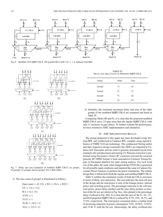
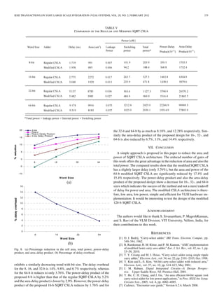
This document summarizes the delay and area analysis of a regular 16-bit square root carry select adder (SQRT CSLA) architecture and a proposed modified architecture. The regular design contains five groups of ripple carry adders of different sizes. The delay and area of each group is evaluated based on the delays of basic blocks like full adders and multiplexers. The proposed design aims to reduce area and power by replacing one ripple carry adder in each group with a binary to excess-1 converter, which requires fewer logic gates. Implementation results show the proposed design has lower area and power with a slight increase in delay compared to the regular SQRT CSLA architecture.
![IEEE TRANSACTIONS ON VERY LARGE SCALE INTEGRATION (VLSI) SYSTEMS, VOL. 20, NO. 2, FEBRUARY 2012 371
(MAD) algorithm introduced in [1], [2] is used for coefficients quanti-zation.
The subfilter is based on canonical signed digit (CSD) structure
and Carry-Save adders are used. Tables III, IV, and V show the results
of area, power, and critical path delay, synthesized by Design Compiler
[10] with 45-nm technology.
VI. CONCLUSION
In this paper, we have presented new parallel FIR filter structures,
which are beneficial to symmetric convolutions when the number of
taps is the multiple of 2 or 3. Multipliers are the major portions in hard-ware
consumption for the parallel FIR filter implementation. The pro-posed
new structure exploits the nature of even symmetric coefficients
and save a significant amount of multipliers at the expense of addi-tional
adders. Since multipliers outweigh adders in hardware cost, it is
profitable to exchange multipliers with adders. Moreover, the number
of increased adders stays still when the length of FIR filter becomes
large, whereas the number of reduced multipliers increases along with
the length of FIR filter. Consequently, the larger the length of FIR fil-ters
is, the more the proposed structures can save from the existing FFA
structures, with respect to the hardware cost. Overall, in this paper, we
have provided new parallel FIR structures consisting of advantageous
polyphase decompositions dealing with symmetric convolutions com-paratively
better than the existing FFA structures in terms of hardware
consumption.
REFERENCES
[1] D. A. Parker and K. K. Parhi, “Low-area/power parallel FIR digital
filter implementations,” J. VLSI Signal Process. Syst., vol. 17, no. 1,
pp. 75–92, 1997.
[2] J. G. Chung and K. K. Parhi, “Frequency-spectrum-based low-area
low-power parallel FIR filter design,” EURASIP J. Appl. Signal
Process., vol. 2002, no. 9, pp. 444–453, 2002.
[3] K. K. Parhi, VLSI Digital Signal Processing Systems: Design and Im-plementation.
New York: Wiley, 1999.
[4] Z.-J. Mou and P. Duhamel, “Short-length FIR filters and their use in
fast nonrecursive filtering,” IEEE Trans. Signal Process., vol. 39, no.
6, pp. 1322–1332, Jun. 1991.
[5] J. I. Acha, “Computational structures for fast implementation of L-path
and L-block digital filters,” IEEE Trans. Circuit Syst., vol. 36, no. 6, pp.
805–812, Jun. 1989.
[6] C. Cheng and K. K. Parhi, “Hardware efficient fast parallel FIR filter
structures based on iterated short convolution,” IEEE Trans. Circuits
Syst. I, Reg. Papers, vol. 51, no. 8, pp. 1492–1500, Aug. 2004.
[7] C. Cheng and K. K. Parhi, “Furthur complexity reduction of parallel
FIR filters,” in Proc. IEEE Int. Symp. Circuits Syst. (ISCAS 2005),
Kobe, Japan, May 2005.
[8] C. Cheng and K. K. Parhi, “Low-cost parallel FIR structures with
2-stage parallelism,” IEEE Trans. Circuits Syst. I, Reg. Papers, vol.
54, no. 2, pp. 280–290, Feb. 2007.
[9] I.-S. Lin and S. K. Mitra, “Overlapped block digital filtering,” IEEE
Trans. Circuits Syst. II, Analog Digit. Signal Process., vol. 43, no. 8,
pp. 586–596, Aug. 1996.
[10] “Design Compiler User Guide,” ver. B-2008.09, Synopsys Inc., Sep.
2008.
Low-Power and Area-Efficient Carry Select Adder
B. Ramkumar and Harish M Kittur
Abstract—Carry Select Adder (CSLA) is one of the fastest adders used
in many data-processing processors to perform fast arithmetic functions.
From the structure of the CSLA, it is clear that there is scope for reducing
the area and power consumption in the CSLA. This work uses a simple and
efficient gate-level modification to significantly reduce the area and power
of the CSLA. Based on this modification 8-, 16-, 32-, and 64-b square-root
CSLA (SQRT CSLA) architecture have been developed and compared with
the regular SQRT CSLA architecture. The proposed design has reduced
area and power as compared with the regular SQRT CSLA with only a
slight increase in the delay. This work evaluates the performance of the
proposed designs in terms of delay, area, power, and their products by
hand with logical effort and through custom design and layout in 0.18- m
CMOS process technology. The results analysis shows that the proposed
CSLA structure is better than the regular SQRT CSLA.
Index Terms—Application-specific integrated circuit (ASIC), area-effi-cient,
CSLA, low power.
I. INTRODUCTION
Design of area- and power-efficient high-speed data path logic sys-tems
are one of the most substantial areas of research in VLSI system
design. In digital adders, the speed of addition is limited by the time
required to propagate a carry through the adder. The sum for each bit
position in an elementary adder is generated sequentially only after the
previous bit position has been summed and a carry propagated into the
next position.
The CSLA is used in many computational systems to alleviate the
problem of carry propagation delay by independently generating mul-tiple
carries and then select a carry to generate the sum [1]. However,
the CSLA is not area efficient because it uses multiple pairs of Ripple
Carry Adders (RCA) to generate partial sum and carry by considering
carry input and , then the final sum and carry are
selected by the multiplexers (mux).
The basic idea of this work is to use Binary to Excess-1 Converter
(BEC) instead of RCA with in the regular CSLA to achieve
lower area and power consumption [2]–[4]. The main advantage of this
BEC logic comes from the lesser number of logic gates than the -bit
Full Adder (FA) structure. The details of the BEC logic are discussed
in Section III.
This brief is structured as follows. Section II deals with the delay
and area evaluation methodology of the basic adder blocks. Section III
presents the detailed structure and the function of the BEC logic. The
SQRT CSLA has been chosen for comparison with the proposed de-sign
as it has a more balanced delay, and requires lower power and
area [5], [6]. The delay and area evaluation methodology of the regular
and modified SQRT CSLA are presented in Sections IV and V, respec-tively.
The ASIC implementation details and results are analyzed in
Section VI. Finally, the work is concluded in Section VII.
Manuscript received May 12, 2010; revised October 28, 2010; accepted De-cember
15, 2010. Date of publication January 24, 2011; date of current version
January 18, 2012.
The authors are with the School of Electronics Engineering, VIT University,
Vellore 632 014, India (e-mail: ramkumar.b@vit.ac.in; kittur@vit.ac.in).
Color versions of one or more of the figures in this paper are available online
at http://ieeexplore.ieee.org.
Digital Object Identifier 10.1109/TVLSI.2010.2101621
1063-8210/$26.00 © 2011 IEEE](https://image.slidesharecdn.com/1-140925124213-phpapp02/85/1-area-efficient-carry-select-adder-1-320.jpg)
![IEEE TRANSACTIONS ON VERY LARGE SCALE INTEGRATION (VLSI) SYSTEMS, VOL. 20, NO. 2, FEBRUARY 2012 371
(MAD) algorithm introduced in [1], [2] is used for coefficients quanti-zation.
The subfilter is based on canonical signed digit (CSD) structure
and Carry-Save adders are used. Tables III, IV, and V show the results
of area, power, and critical path delay, synthesized by Design Compiler
[10] with 45-nm technology.
VI. CONCLUSION
In this paper, we have presented new parallel FIR filter structures,
which are beneficial to symmetric convolutions when the number of
taps is the multiple of 2 or 3. Multipliers are the major portions in hard-ware
consumption for the parallel FIR filter implementation. The pro-posed
new structure exploits the nature of even symmetric coefficients
and save a significant amount of multipliers at the expense of addi-tional
adders. Since multipliers outweigh adders in hardware cost, it is
profitable to exchange multipliers with adders. Moreover, the number
of increased adders stays still when the length of FIR filter becomes
large, whereas the number of reduced multipliers increases along with
the length of FIR filter. Consequently, the larger the length of FIR fil-ters
is, the more the proposed structures can save from the existing FFA
structures, with respect to the hardware cost. Overall, in this paper, we
have provided new parallel FIR structures consisting of advantageous
polyphase decompositions dealing with symmetric convolutions com-paratively
better than the existing FFA structures in terms of hardware
consumption.
REFERENCES
[1] D. A. Parker and K. K. Parhi, “Low-area/power parallel FIR digital
filter implementations,” J. VLSI Signal Process. Syst., vol. 17, no. 1,
pp. 75–92, 1997.
[2] J. G. Chung and K. K. Parhi, “Frequency-spectrum-based low-area
low-power parallel FIR filter design,” EURASIP J. Appl. Signal
Process., vol. 2002, no. 9, pp. 444–453, 2002.
[3] K. K. Parhi, VLSI Digital Signal Processing Systems: Design and Im-plementation.
New York: Wiley, 1999.
[4] Z.-J. Mou and P. Duhamel, “Short-length FIR filters and their use in
fast nonrecursive filtering,” IEEE Trans. Signal Process., vol. 39, no.
6, pp. 1322–1332, Jun. 1991.
[5] J. I. Acha, “Computational structures for fast implementation of L-path
and L-block digital filters,” IEEE Trans. Circuit Syst., vol. 36, no. 6, pp.
805–812, Jun. 1989.
[6] C. Cheng and K. K. Parhi, “Hardware efficient fast parallel FIR filter
structures based on iterated short convolution,” IEEE Trans. Circuits
Syst. I, Reg. Papers, vol. 51, no. 8, pp. 1492–1500, Aug. 2004.
[7] C. Cheng and K. K. Parhi, “Furthur complexity reduction of parallel
FIR filters,” in Proc. IEEE Int. Symp. Circuits Syst. (ISCAS 2005),
Kobe, Japan, May 2005.
[8] C. Cheng and K. K. Parhi, “Low-cost parallel FIR structures with
2-stage parallelism,” IEEE Trans. Circuits Syst. I, Reg. Papers, vol.
54, no. 2, pp. 280–290, Feb. 2007.
[9] I.-S. Lin and S. K. Mitra, “Overlapped block digital filtering,” IEEE
Trans. Circuits Syst. II, Analog Digit. Signal Process., vol. 43, no. 8,
pp. 586–596, Aug. 1996.
[10] “Design Compiler User Guide,” ver. B-2008.09, Synopsys Inc., Sep.
2008.
Low-Power and Area-Efficient Carry Select Adder
B. Ramkumar and Harish M Kittur
Abstract—Carry Select Adder (CSLA) is one of the fastest adders used
in many data-processing processors to perform fast arithmetic functions.
From the structure of the CSLA, it is clear that there is scope for reducing
the area and power consumption in the CSLA. This work uses a simple and
efficient gate-level modification to significantly reduce the area and power
of the CSLA. Based on this modification 8-, 16-, 32-, and 64-b square-root
CSLA (SQRT CSLA) architecture have been developed and compared with
the regular SQRT CSLA architecture. The proposed design has reduced
area and power as compared with the regular SQRT CSLA with only a
slight increase in the delay. This work evaluates the performance of the
proposed designs in terms of delay, area, power, and their products by
hand with logical effort and through custom design and layout in 0.18- m
CMOS process technology. The results analysis shows that the proposed
CSLA structure is better than the regular SQRT CSLA.
Index Terms—Application-specific integrated circuit (ASIC), area-effi-cient,
CSLA, low power.
I. INTRODUCTION
Design of area- and power-efficient high-speed data path logic sys-tems
are one of the most substantial areas of research in VLSI system
design. In digital adders, the speed of addition is limited by the time
required to propagate a carry through the adder. The sum for each bit
position in an elementary adder is generated sequentially only after the
previous bit position has been summed and a carry propagated into the
next position.
The CSLA is used in many computational systems to alleviate the
problem of carry propagation delay by independently generating mul-tiple
carries and then select a carry to generate the sum [1]. However,
the CSLA is not area efficient because it uses multiple pairs of Ripple
Carry Adders (RCA) to generate partial sum and carry by considering
carry input and , then the final sum and carry are
selected by the multiplexers (mux).
The basic idea of this work is to use Binary to Excess-1 Converter
(BEC) instead of RCA with in the regular CSLA to achieve
lower area and power consumption [2]–[4]. The main advantage of this
BEC logic comes from the lesser number of logic gates than the -bit
Full Adder (FA) structure. The details of the BEC logic are discussed
in Section III.
This brief is structured as follows. Section II deals with the delay
and area evaluation methodology of the basic adder blocks. Section III
presents the detailed structure and the function of the BEC logic. The
SQRT CSLA has been chosen for comparison with the proposed de-sign
as it has a more balanced delay, and requires lower power and
area [5], [6]. The delay and area evaluation methodology of the regular
and modified SQRT CSLA are presented in Sections IV and V, respec-tively.
The ASIC implementation details and results are analyzed in
Section VI. Finally, the work is concluded in Section VII.
Manuscript received May 12, 2010; revised October 28, 2010; accepted De-cember
15, 2010. Date of publication January 24, 2011; date of current version
January 18, 2012.
The authors are with the School of Electronics Engineering, VIT University,
Vellore 632 014, India (e-mail: ramkumar.b@vit.ac.in; kittur@vit.ac.in).
Color versions of one or more of the figures in this paper are available online
at http://ieeexplore.ieee.org.
Digital Object Identifier 10.1109/TVLSI.2010.2101621
1063-8210/$26.00 © 2011 IEEE](https://image.slidesharecdn.com/1-140925124213-phpapp02/75/1-area-efficient-carry-select-adder-1-2048.jpg)
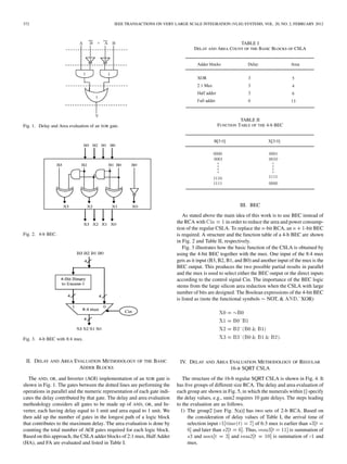
![IV. DELAY AND AREA EVALUATION METHODOLOGY OF REGULAR
16-B SQRT CSLA
The structure of the 16-b regular SQRT CSLA is shown in Fig. 4. It
has five groups of different size RCA. The delay and area evaluation of
each group are shown in Fig. 5, in which the numerals within [] specify
the delay values, e.g., sum2 requires 10 gate delays. The steps leading
to the evaluation are as follows.
1) The group2 [see Fig. 5(a)] has two sets of 2-b RCA. Based on
.
the consideration of delay values of Table I, the arrival time of
selection input of 6:3 mux is earlier than
and later than Thus, is summation of
and and](https://image.slidesharecdn.com/1-140925124213-phpapp02/85/1-area-efficient-carry-select-adder-3-320.jpg)